


English |
page |
1-18 |
Deutsch |
Seite |
19-36 |
Français |
page |
37-54 |
Italiano |
pagine 55-72 |
|
Español |
pagina 73-90 |
|
Nederlands pagina 91-108
GB
C 10
D
C 10
F
C 10
I
C 10
E
C 10
NL
C 10
ETRTO |
|
WS in mm KMH |
47-305 |
16x1,75 |
1272 |
47-406 |
20x1,75 |
1590 |
34-540 |
24x1 3/8 |
1948 |
47-507 |
24x1,75 |
1907 |
23-571 |
26x1 |
1973 |
40-559 |
26x1,5 |
2026 |
44-559 |
26x1,6 |
2051 |
47-559 |
26x1,75 |
2070 |
50-559 |
26x1,9 |
2089 |
54-559 |
26x2,00 |
2114 |
57-559 |
26x2,125 |
2133 |
37-590 |
26x1 3/8 |
2105 |
20-571 |
26x3/4 |
1954 |
|
|
ETRTO |
|
|
32-630 |
|
|
40-622 |
|
|
47-622 |
|
|
40-635 |
|
|
37-622 |
|
|
18-622 |
|
|
20-622 |
|
|
23-622 |
|
|
25-622 |
|
|
28-622 |
|
|
32-622 |
|
|
37-622 |
|
|
40-622 |
WS in inch MPH
50,1
62,6
76,7
75,1
77,7
79,8
80,7
81,5
82,2
83,2
84,0
82,9
76,9
|
WS in mm KMH |
WS in inch MPH |
27x1 1/4 |
2199 |
86,6 |
28x1,5 |
2224 |
87,6 |
28x1,75 |
2268 |
89,3 |
28x1 1/2 |
2265 |
89,2 |
28x1 3/8 |
2205 |
86,8 |
700x18C |
2102 |
82,8 |
700x20C |
2114 |
83,2 |
700x23C |
2133 |
84,0 |
700x25C |
2146 |
84,5 |
700x28C |
2149 |
84,6 |
700x32C |
2174 |
85,6 |
700x37C |
2205 |
86,8 |
700x40C |
2224 |
87,6 |

INSTALLATION AND OPERATION MANUAL - VDO CYTEC C 10
Preface
Thank you for buying a VDO CYTEC bicycle computer. The more familiar you get with this model, the more enjoyable your trips are going to be.
Please read thoroughly all the information provided in this manual. You are getting important and useful hints for operation to make you fully benefit from all the technical features of your VDO CYTEC bicycle computer.
We wish you enjoyable trips and rides on your bike with VDO CYTEC
CYCLE PARTS GMBH
Mounting the system
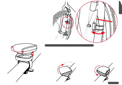
1. Mounting the handlebar holder
The handlebar holder fits handlebars of any diameter. Before mounting the system, decide if you will be using your left or right hand to operate the computer and then mount the handlebar holder on the respective side. Position the handlebar holder, insert the strap and adjust it by tightening the screw.
Warning: Before tightening the handlebar holder, make sure to adjust the position of the computer head (inclination) when the LCD-display is best visible for you. Only when you find the best position tighten the screw.
GB
C 10
screw
1

GB
C 10
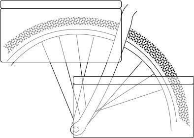
3. Mounting the spoke magnet
Distance between magnet and sensor should be approx. 1-5 mm.
 2. Mounting the speed transmitter
The sensor should be mounted on the same side of the fork as the holder is on the handlebar.
Watch out: Do not tighten the cable ties yet! Accurately position the spoke magnet and the sensor first, then tighten the cable ties.
2
In case this distance is not achievable in the current positioning, slide the sensor and the magnet on the fork or spoke accordingly.
 1-5mm
1-5mm
GB
C 10

 -5mm
-5mm
LOCK |
|
4. Twist-Click mounting of computer onto holder |
|
|
UNLOCK |
The Twist-Click mounting has been exclusively developed for the new line of VDO |
|
|
CYTEC computers. |
|
|
|
|
|
|
|
|
The computerhead is put onto the handlebar and by a right turn of the computerhead |
|
|
|
(TWIST) fixed to the holder (CLICK). |
|
|
|
It is just as easy to remove the computerhead from the handlebar holder. |
|
|
|
Slightly push the computerhead down, twist it to the left, remove computerhead from |
|
|
|
handlebar holder. |
2.CLICK |
1.LOCK
 1.PRESS

2.UNLOCK
3
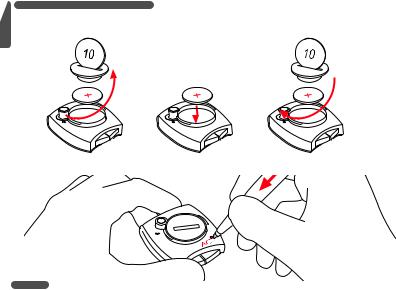
5. Installing battery into computer head
GB |
|
C |
To save battery power, your VDO CYTEC comes with the battery not yet fitted. Prior to initial use you have to install the battery first. |
|
|
10 |
|
OPEN |
CLOSE |
If you find the computer is not functioning properly after a battery change, push the AC-button (Auto Clear) on the rear side of the computer to reset.
4
 Loading...