


8410 Wireless Field
Transceiver
Transmitter and receiver for wireless
RS-232 and RS-485 data
Installation and Operations Manual
communications
IOM095GVAE4112
Automation Solutions for oil & gas, defense and aviation applications


Copyright
All rights reserved. Printed in the United States of America.
Except as permitted under the United States Copyright Act of 1976, no part of this publication
may be reproduced, stored in a retrieval system or transmitted in any form or by any means electronic, mechanical, photocopying, recording, or otherwise - without the prior written
permission of the Publisher:
Varec, Inc.
5834 Peachtree Corners East
Norcross (Atlanta), Georgia 30092
Phone: (770) 447-9202
Fax: (770) 662-8939
Trademarks Acknowledged
Varec, Inc. recognizes all other trademarks. Trademarks of other products mentioned in this
manual are held by the companies producing them.
FuelsManager®, TankView®, TacFuels®, Varec®, and FuelsManager IntoPlane® are registered
trademarks of Varec, Inc.
FreeWave® is a registered trademark of FreeWave Technologies, Inc.
All other product and service names mentioned are the trademarks of their respective
companies.
Varec, Inc. iii

Disclaimer of Warranties
The contract between the Seller and the Buyer states the entire obligation of the Seller. The
contents of this instruction manual shall not become part of or modify any prior or existing
agreement, commitment, or relationship between the Seller and Buyer. There are no express or
implied warranties set out in this instruction manual. The only warranties that apply are those
in the existing contract between the Seller and Buyer.
The 8410 Wireless Field Transceiver (WFT) has not been tested by Varec under all possible
operational conditions, and Varec may not have all the data relative to your application. The
information in this instruction manual is not all inclusive and does not and cannot take into
account all unique situations. Consequently, the user should review this product literature in
view of his or her application. If you have any further questions, please contact Varec for
assistance.
Limitations of Seller's Liability
In the event that a court holds that this instruction manual created some new warranties, Seller's
liability shall be limited to repair or replacement under the standard warranty clause. In no case
shall the Seller's liability exceed that stated as Limitations of Remedy in the contract between
the Seller and Buyer.
Use of parts that are not manufactured or supplied by Varec voids any warranty and relieves
Varec of any obligation to service the product under warranty. Varec recommends the use of
only Varec manufactured or supplied parts to maintain or service Varec 8410 Wireless Field
Transceivers.
Terms of Use
The information provided in this document is provided "as is” without warranty of any kind.
Varec, Inc. disclaim all warranties, either express or implied, including the warranties of
merchantability and fitness for a particular purpose. In no event shall Varec, Inc. or its suppliers
be liable for any damages whatsoever including direct, indirect, incidental, consequential, loss
of business profits or special damages, even if Varec, Inc. or its suppliers have been advised of
the possibility of such damages.
This manual is solely intended to describe product installation and functions and should not be
used for any other purpose. It is subject to change without prior notice. This manual was
prepared with the highest degree of care. However, should you find any errors or have any
questions, contact one of our service offices or your local sales agent.
iv Installation and Operations Manual

Safety Precaution Definitions
Caution! Damage to equipment may result if this precaution is disregarded.
Warning! Direct injury to personnel or damage to equipment which can cause injury to
personnel may result if this precaution is not followed.
Safety Precautions
Read this manual carefully and make sure you understand its contents before using this product.
Follow all instructions and safety guidelines presented in this manual when using this product.
If the user does not follow these instructions properly, Varec cannot guarantee the safety of the
system.
Note Comply with all applicable regulations, codes, and standards. For safety precautions,
the user should refer to the appropriate industry or military standards.
Caution! Electrical Hazard! Read and understand static and lightning electrical protection
and grounding described in API 2003. Make certain that the tank installation, operation,
and maintenance conforms with the practice set forth therein.
Varec, Inc. v

Restricted Rights
This product is licensed by The United States. Diversion contrary to U.S. law is prohibited.
Shipment or re-export of this product outside of The United States may require authorization
by the U.S. Bureau of Export Administration. Please contact Varec, Inc. for assistance and further
information.
FCC Notifications
This device complies with part 15 of the FCC rules. Operation is subject to the following two
conditions: 1) This device may not cause harmful interference and 2) this device must accept
any interference received, including interference that may cause undesired operation. This
device must be operated as supplied by Varec, Inc. Any changes or modifications made to the
device without the express written approval of Varec, Inc. may void the user’s authority to
operate the device.
This equipment has been tested and found to comply with the limits for a Class B digital device,
pursuant to part 15 of the FCC Rules. These limits are designed to provide reasonable protection
against harmful interference in a residential installation. This equipment generates, uses, and
can radiate radio frequency energy and, if not installed and used in accordance with the
instructions, may cause harmful interference to radio communications. However, there is no
guarantee that interference will not occur in a particular installation. If this equipment does
cause harmful interference to radio or television reception, which can be determined by turning
the equipment off and on, the user is encouraged to try to correct the interference by one or
more of the following measures:
• Reorient or relocate the receiving antenna.
• Increase the separation between the equipment and receiver.
• Connect the equipment into an outlet on a circuit different from that to which the receiver is
connected.
• Consult the dealer or an experienced radio/TV technician for help.
vi Installation and Operations Manual

Contents
Wireless Field Transceiver
1 Introduction. . . . . . . . . . . . . . . . . . . . . . . . . . . . . . . . . . . . . . . . . . . . . . . . . . . . . 1
1.1 Overview. . . . . . . . . . . . . . . . . . . . . . . . . . . . . . . . . . . . . . . . . . . . . . . . . . . . . . . 1
1.2 Function and System Design . . . . . . . . . . . . . . . . . . . . . . . . . . . . . . . . . . . . . . . 2
1.2.1 Internal system design . . . . . . . . . . . . . . . . . . . . . . . . . . . . . . . . . . . . . . . . 3
1.3 Understanding Data Communication Configurations . . . . . . . . . . . . . . . . . . . . . 4
1.3.1 Point-to-Point systems . . . . . . . . . . . . . . . . . . . . . . . . . . . . . . . . . . . . . . . . 4
1.3.2 Point-to-Multipoint systems. . . . . . . . . . . . . . . . . . . . . . . . . . . . . . . . . . . . . 5
1.4 Choosing Point-to-Point or Point-to-Mult ipo int Operation. . . . . . . . . . . . . . . . . . 6
2 Preparing for Installation. . . . . . . . . . . . . . . . . . . . . . . . . . . . . . . . . . . . . . . . 7
2.1 Pre-Installation Checklist . . . . . . . . . . . . . . . . . . . . . . . . . . . . . . . . . . . . . . . . . . 7
2.2 General Safety Guidelines . . . . . . . . . . . . . . . . . . . . . . . . . . . . . . . . . . . . . . . . . 8
2.3 Unpacking. . . . . . . . . . . . . . . . . . . . . . . . . . . . . . . . . . . . . . . . . . . . . . . . . . . . . . 8
2.4 Installation Overview. . . . . . . . . . . . . . . . . . . . . . . . . . . . . . . . . . . . . . . . . . . . . . 9
2.5 Installation Checklist . . . . . . . . . . . . . . . . . . . . . . . . . . . . . . . . . . . . . . . . . . . . . 10
2.5.1 Identifying your sites . . . . . . . . . . . . . . . . . . . . . . . . . . . . . . . . . . . . . . . . 10
2.5.2 Completing a site study . . . . . . . . . . . . . . . . . . . . . . . . . . . . . . . . . . . . . . 10
2.5.3 Selecting an antenna . . . . . . . . . . . . . . . . . . . . . . . . . . . . . . . . . . . . . . . . 10
2.5.4 Configuring radios . . . . . . . . . . . . . . . . . . . . . . . . . . . . . . . . . . . . . . . . . . 11
2.5.5 Installing cables and antennas properly . . . . . . . . . . . . . . . . . . . . . . . . . . . 11
2.5.6 Surge protection . . . . . . . . . . . . . . . . . . . . . . . . . . . . . . . . . . . . . . . . . . . 11
3 Mounting. . . . . . . . . . . . . . . . . . . . . . . . . . . . . . . . . . . . . . . . . . . . . . . . . . . . . . . 13
3.1 Installation Safety Guidelines . . . . . . . . . . . . . . . . . . . . . . . . . . . . . . . . . . . . . . 13
4 Wiring. . . . . . . . . . . . . . . . . . . . . . . . . . . . . . . . . . . . . . . . . . . . . . . . . . . . . . . . . . 15
4.1 8410 WFT Connectors, Switches, and Wiring Diagram (AC Version) . . . . . . . 16
4.1.1 Connector assignments for the AC version. . . . . . . . . . . . . . . . . . . . . . . . . 17
4.2 8410 WFT Connectors, Switches, and Low Voltage Wiring Diagram
(DC Version) . . . . . . . . . . . . . . . . . . . . . . . . . . . . . . . . . . . . . . . . . . . . . . 18
4.2.1 Connector assignments for the low voltage version . . . . . . . . . . . . . . . . . . . 19
5 Setting Up the Transceiver Using Tool Suite . . . . . . . . . . . . . . . . . . . 21
5.1 Setting Up a Transceiver Using Tool Suite . . . . . . . . . . . . . . . . . . . . . . . . . . . . 21
6 LED Operations . . . . . . . . . . . . . . . . . . . . . . . . . . . . . . . . . . . . . . . . . . . . . . . . 23
6.1 LED Operations on a Point-to-Multipoint Syst em . . . . . . . . . . . . . . . . . . . . . . . 23
6.1.1 Point-to-Multipoint operation LEDs . . . . . . . . . . . . . . . . . . . . . . . . . . . . . . 24
6.2 LED Operations on a Point-to-Point System. . . . . . . . . . . . . . . . . . . . . . . . . . . 25
6.2.1 Point-to-Point operation LEDs. . . . . . . . . . . . . . . . . . . . . . . . . . . . . . . . . . 25
Varec, Inc. vii

Contents
7 Factory Default Settings . . . . . . . . . . . . . . . . . . . . . . . . . . . . . . . . . . . . . . . 27
8 Specifications. . . . . . . . . . . . . . . . . . . . . . . . . . . . . . . . . . . . . . . . . . . . . . . . . . 29
8.1 General . . . . . . . . . . . . . . . . . . . . . . . . . . . . . . . . . . . . . . . . . . . . . . . . . . . . . . . 29
8.2 Transmit . . . . . . . . . . . . . . . . . . . . . . . . . . . . . . . . . . . . . . . . . . . . . . . . . . . . . . 29
8.3 Receive. . . . . . . . . . . . . . . . . . . . . . . . . . . . . . . . . . . . . . . . . . . . . . . . . . . . . . . 30
8.4 Data Transmission . . . . . . . . . . . . . . . . . . . . . . . . . . . . . . . . . . . . . . . . . . . . . . 30
8.5 Power Requirements . . . . . . . . . . . . . . . . . . . . . . . . . . . . . . . . . . . . . . . . . . . . 31
8.6 Operating Environment. . . . . . . . . . . . . . . . . . . . . . . . . . . . . . . . . . . . . . . . . . . 31
9 Ordering Information. . . . . . . . . . . . . . . . . . . . . . . . . . . . . . . . . . . . . . . . . . . 33
9.1 Order Codes . . . . . . . . . . . . . . . . . . . . . . . . . . . . . . . . . . . . . . . . . . . . . . . . . . . 33
viii Installation and Operations Manual

1 Introduction
1.1 Overview
Wireless Field Transceiver
This manual provides the information that the user needs to install, maintain, and troubleshoot
the Varec 8410 Wireless Field Transceiver (8410 WFT).
The 8410 WFT provides secure wireless communications between the field instrument and the
8420 Wireless Base Transceiver (WBT), which is located in the control room. Both units are able
to provide simultaneous slave/repeater functionality.
The 8410 WFT and the 8420 WBT provide wireless links between a variety of instruments and
devices. The units can be configured to provide wireless communications with most RS-232 and
RS-485 serial devices including the Varec 4590 TSM, Varec 2900 FTT, and Varec 8130 RTU.
Varec, Inc. 1

Introduction
1.2 Function and System Design
The 8410 WFT provides wireless 900 MHz RS-232 and RS-485 data communications.
Point-to-MultiPoint
Mo
de
16
l
8
xx
4
xx
20
xx-
8420
1
58
Wire
3
4
Pe
l
a
es
ch
t
re
s
e
B
C
orner
a
se Tra
s
V
E
a
a
re
st
c, In
No
n
c
rcro
sc
.
C
s
e
s
D
i
(At
v
T
e
l
anta
X
r
M
ad
C
)
G
e
TS
e
in US
o
r
gia
3
A
00
9
2 USA
FuelsManager
Software
Master
WBT
8130 RTU
or
8300 TGI
CPU
+24V
+5V
COMM
I/O
+15V
ERROR
-15V
Slave
Repeater
Slave
\
Loop Communcations e.g. Modbus
Slave
M
odel
1
6-xxxxxx
8
420
-1
8420
5
Wirel
83
4 Peacht
e
ss Bas
re
e
Corn
ers
e
Va
East N
Tra
rec
,
In
ns
orcr
c.
ceiver
oss (At
CD
T
l
an
X
Mad
t
a) Georgi
CT
e
in
S
US
a
A
3
009
2
USA
Point-to-Point
Field
Model
16-x
8420
xxxx
x-
8420
1
58
W
34
ireles
P
ea
ch
t
r
s
ee
Ba
Cor
n
s
ers
e
V
E
Tran
are
a
s
c,
t N
Inc.
o
rcros
scei
C
s (
D
v
Atl
TX
er
a
n
M
t
a
a
CTS
) Geo
d
e in
r
US
g
ia
A
30
0
92
U
S
A
Junction Box
Star Communcations e.g. Mark/Space
Figure 1-1: Example of Point-to-Point and Multipoint Systems
Varec’s wireless products are able to function over point-to-point or multipoint systems.
Traditionally, a multipoint network is used in applications where data is collected from many
instruments and reported back to one central site.
Note It is important to note the differences between point-to-point and point-to-multipoint systems. In a point-to-point system all data communications are acknowledged,
whether sent from the master to the slave or from the slave to the master. In a point-tomultipoint system outbound communications from the master are sent a user-defined
number of times. The receiving unit, slave or repeater, will accept the first packet received
that meets security requirements. A point-to-point system is limited to one master and one
slave transceiver. Repeaters may be added to extend the reach of the network, but no other
master or slave may be added. In a point-to-multipoint system, the transceiver—designated as a master— is able to communicate with numerous slaves. In its simplest form, a
tank gauge multipoint network functions with the master (8420 WBT) broadcasting its messages to all slaves (8410 WFT) and the slaves responding to the master when given data by
the connected tank gauge transmitter.
2 Installation and Operations Manual

Wireless Field Transceiver
1.2.1 Internal system design
A. Antenna
B. Antenna Feed-Thru
C. Electronics Assembly
D. O-Ring
E. Housing
All standard electronics for the 8410 WFT are contained on the circuit board (C). This includes
power, field communications, a 3-wire temperature input, and a 24V DC out.
A
B
C
D
Figure 1-2: 8410 WFT System Components
Varec, Inc. 3
E

Introduction
T
8420 WBT 8410 WFT
8410 WFT
8410 WFT
1.3 Understanding Data Communication Configurations
The 8410 WFT’s versatility allows the user to establish data communication links using a variety
of configurations. This makes it possible to extend the range of the 8410 WFT and operate in a
number of applications. This section describes the two main categories of communication
configurations: Point-to-Point and Point-to-Multipoint.
1.3.1 Point-to-Point systems
A point-to-point system is limited to one master and one slave transceiver. Repeaters may be
added in to extend the reach of the network, but no other master or slave may be added.
The example below shows the most common and straightforward link, a master communicating
to a slave in a point-to-point link.
8420 WBT 8410 WFT
Figure 1-3: A Master Communicating to a Slave in a Point-to-Point Link
The following diagram shows how a link might be set up using a repeater. The repeater may be
sitting on a hilltop or other elevated structure to link the master to the slave. In this setup, it
may be desirable to use an external omni-directional antenna on the repeater. To extend the
range, Yagi antennas may be used on either or both of the master and slave transceiver.
When a repeater is used, the network capacity is cut in half.
8420 WBT
Figure 1-4: A Link Setup Using a Repeater
8410 WFT
8410 WF
The example below shows a link with two repeaters between the master and slave. With two
repeaters there is clearly more flexibility in getting around obstacles and a greater total range
is possible. Once again, it would be desirable to use external omni-directional antennas with
the repeaters, and attaching a Yagi to the master and slave to increase the range of the link.
When two repeaters are used there is no further degradation in the network capacity of the link.
Figure 1-5: A Link with Two Repeaters Between the Master and Slave
4 Installation and Operations Manual
Wireless Field Transceiver
8410
WFT
8410
8420
8410
WFT
WBT
8410
8410
8410
8410
8410
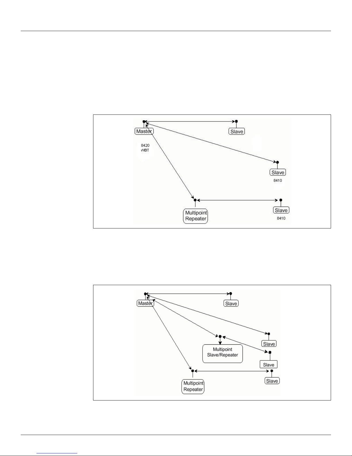
1.3.2 Point-to-Multipoint systems
In a point-to-multipoint system the transceiver, designated as a master, is able to communicate
with numerous slaves. In its simplest form, a multipoint network functions with the master
broadcasting its messages to all slaves and the slaves responding to the master when given data
by the device connected to the data port.
Figure 1-6 depicts a standard point-to-multipoint system. In this example, any data sent from
the master is broadcasted to all three slaves, one of which receives it through a multipoint
repeater. The data is in turn sent out of the RS-232 or RS-485 port of each of the three slaves.
Figure 1-6: A Standard Point-to-Multipoint System Using a Multipoint Repeater
Figure 1-7 shows a point-to-multipoint system using a slave/repeater at one of the sites. This
system works in the same manner as a standard multipoint system with repeaters. However, the
number of radios needed is reduced with the use of the multipoint slave/repeater feature.
Figure 1-7: A Point-to-Multipoint System Using the Multipoint Slave/Repeater Feature
Varec, Inc. 5
 Loading...