

Page 1

VCBA VERSION 10.xx SOFTWARE MANUAL REV 2
TABLE OF CONTENTS
CONVENTIONS USED IN THIS DOCUMENT ..................................................................................... 1
1.0 INTRODUCTION .................................................................................................................. .. 2
1.1 System Requirements ...................................................................................................... 2
2.0 SOFTWARE INSTALLATION ................................................................................................... 3
3.0 STARTING THE VCBA SOFTWARE ......................................................................................... 6
3.1 Main Menu Item Descriptions ......................................................................................... 6
3.2 Enabling the Computer Interface ..................................................................................... 8
3.3 Application Setup ........................................................................................................... 10
4.0 WORKING WITH TEST RECORDS ........................................................................................ 12
4.1 Exploring the Test Records Directory ............................................................................. 12
4.2 Retrieving Test Records From a CB Analyzer ................................................................. 12
4.2.1. Retrieve Test Records From Timer ......................................................................... 12
4.2.2. Retrieve Test Records to Directory ......................................................................... 14
4.3 Recalling Test Records From the PC Hard Drive ............................................................ 15
4.4 Saving a Test Record ...................................................................................................... 17
4.4.1. Saving a Test Record with its Original File Name.................................................... 17
4.4.2. Saving a Test Record with a Different File Name ................................................... 17
4.5 Copying a Test Record .................................................................................................... 18
4.6 Renaming a Test Record ................................................................................................. 19
4.7 Deleting a Test Record ................................................................................................... 20
4.8 Merging Test Records ..................................................................................................... 21
4.9 Exporting a Test Record in Microsoft® Excel® Format .................................................... 22
4.10 Viewing and Working with Tabulated Test Results .................................................... 24
4.10.1. Viewing the Test Plan for a Test Record ............................................................. 25
4.10.2. Printing Tabulated Test Results ........................................................................... 27
4.11 Viewing and Working with Graphic Test Results ........................................................ 30
4.11.1. Toggling the Display of the Velocity Curve ......................................................... 31
4.11.2. Customizing the Items Displayed on the Graphic Results Screen ....................... 33
4.11.3. Customizing the Graph Colors ............................................................................. 34
4.11.4. Overlaying Two Timing Shots .............................................................................. 35
4.11.5. Viewing a Graph Expansion ................................................................................. 37
4.11.6. Calculating the Average Velocity From the Graphic Test Results ....................... 40
4.11.7. Manually Overriding Contact Time/Resistor Contact Time or Contact Wipe ..... 42
4.11.8. Printing the Graphic Test Results ........................................................................ 46
4.12 Test Record Diagnostic Tools ...................................................................................... 47
4.12.1. Viewing Raw Shot Data ....................................................................................... 47
4.12.2. Toggling the Resistor Flag ................................................................................... 48
5.0 WORKING WITH TEST PLANS ............................................................................................. 49
5.1 Exploring the Test Plans Directory ................................................................................. 49
5.2 Creating a Circuit Breaker Test Plan ............................................................................... 49
5.3 Modifying an Existing Circuit Breaker Test Plan ............................................................ 60
i
Page 2

REV 2 VCBA VERSION 10.xx SOFTWARE MANUAL
5.4 Retrieving a Test Plan from a CB Analyzer ..................................................................... 63
5.5 Saving a Test Plan ........................................................................................................... 65
5.6 Saving a Test Plan from a Test Record ........................................................................... 65
5.7 Transferring a Test Plan to a CB Analyzer ...................................................................... 66
5.8 Copying a Test Plan to a Different Location ................................................................... 68
5.9 Deleting a Test Plan ........................................................................................................ 69
5.10 Using a Test Plan for a Timing Test ............................................................................. 70
5.11 Printing a Test Plan ..................................................................................................... 71
6.0 TIMING A CIRCUIT BREAKER USING THE VCBA SOFTWARE............................................... 72
6.1 Performing an OPEN or CLOSE test ................................................................................ 72
6.2 Performing an OPEN-CLOSE test .................................................................................... 74
6.3 Performing a CLOSE-OPEN test ...................................................................................... 76
6.4 Performing an OPEN-CLOSE-OPEN test ......................................................................... 78
LIST OF FIGURES
Figure 1 Test Record in VCBA Software and Microsoft Excel ....................................................... 23
Figure 2 Typical CB Tabulated Test Report ................................................................................... 28
Figure 3 Typical CB Test Parameters ............................................................................................. 29
Figure 4 Graphic Test Results ........................................................................................................ 30
Figure 5 Typical Graphic Results Printout ..................................................................................... 46
ii
Page 3
VCBA VERSION 10.xx SOFTWARE MANUAL REV 2
CONVENTIONS USED IN THIS DOCUMENT
This document uses the following conventions:
• Microsoft® Windows XP and Vista will be simply referred to as Windows in this manual
The general term “CB analyzer” used in this manual refers to any of the VCBA compatible
•
Vanguard circuit breaker analyzer models (CT-6500, CT-7000, CT-7500, DigiTMR)
•
Menu Names are referred to as Menu Name
• Menu items are referred to as Menu Item
• Dialog boxes and their elements (buttons, options, etc.) are referred to as “Dialog Box
Element”
•
PC keyboard keys are referred to as [Key]. Key combinations are shown as [Key]+[Key].
•
A key or switch on the CB analyzer is indicated as [KEY]
•
File locations, directories, and file names are shown as “C:\folder\filename”
CB analyzer menu options are referenced as (MENU OPTION)
•
• A CB analyzer’s LCD screen output is shown as:
1. OPTION 1
2. OPTION 2
3. OPTION 3
4. OPTION 4
• Warning messages are indicated as:
Warning message
WARNING
• Important notes are indicated as:
Note details
NOTE
Microsoft, Windows, Windows XP, and Windows Vista are either registered trademarks or trademarks of Microsoft Corporation
in the United States and/or other countries. All other trademarks are the property of their respective owners.
1
Page 4

REV 2 VCBA VERSION 10.xx SOFTWARE MANUAL
1.0 INTRODUCTION
The Vanguard Circuit Breaker Analyzer (VCBA) software is a Windows-based PC software
application for use with Vanguard’s CT-6500, CT-7000, CT-7500, and DigiTMR circuit breaker
analyzers. This software allows users to perform the following tasks:
• Retrieve Timing Records from a CB analyzer
• Analyze retrieved Timing Records
• View Test Results in Graphic Format
• Generate Timing Reports
• Create Breaker Test Plans
• Transfer Breaker Test Plans to a CB analyzer
• Control a CB analyzer from the PC to perform Timing Tests
1.1 System Requirements
The VCBA software has the following minimum system requirements:
• PC running Microsoft® Windows® XP or Windows® Vista
• CD-ROM or DVD-ROM drive
• RS-232C (serial) port
2
Page 5
VCBA VERSION 10.xx SOFTWARE MANUAL REV 2
2.0 SOFTWARE INSTALLATION
Follow the steps below to install the VCBA software on your PC.
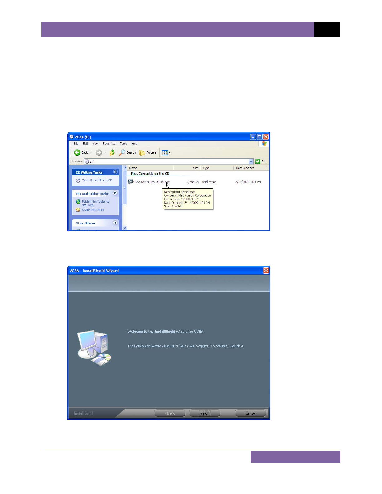
1. Insert the installation CD in the PC’s CD or DVD drive.
2. From the Windows Desktop, click on the “Start” button to bring up the Start Menu.
3. From the Start Menu, click on My Computer to open the My Computer window.
4. Double click (or single click in some Windows configurations) on your CD/DVD Drive icon
to navigate the installation CD. The contents of the CD will be listed as shown below:
5. Double click (or single click in some Windows configurations) on the “VCBA Setup Rev
10.xx.exe” file to start the installation process. The VCBA InstallShield Wizard will appear
as shown below:
3
Page 6
REV 2 VCBA VERSION 10.xx SOFTWARE MANUAL
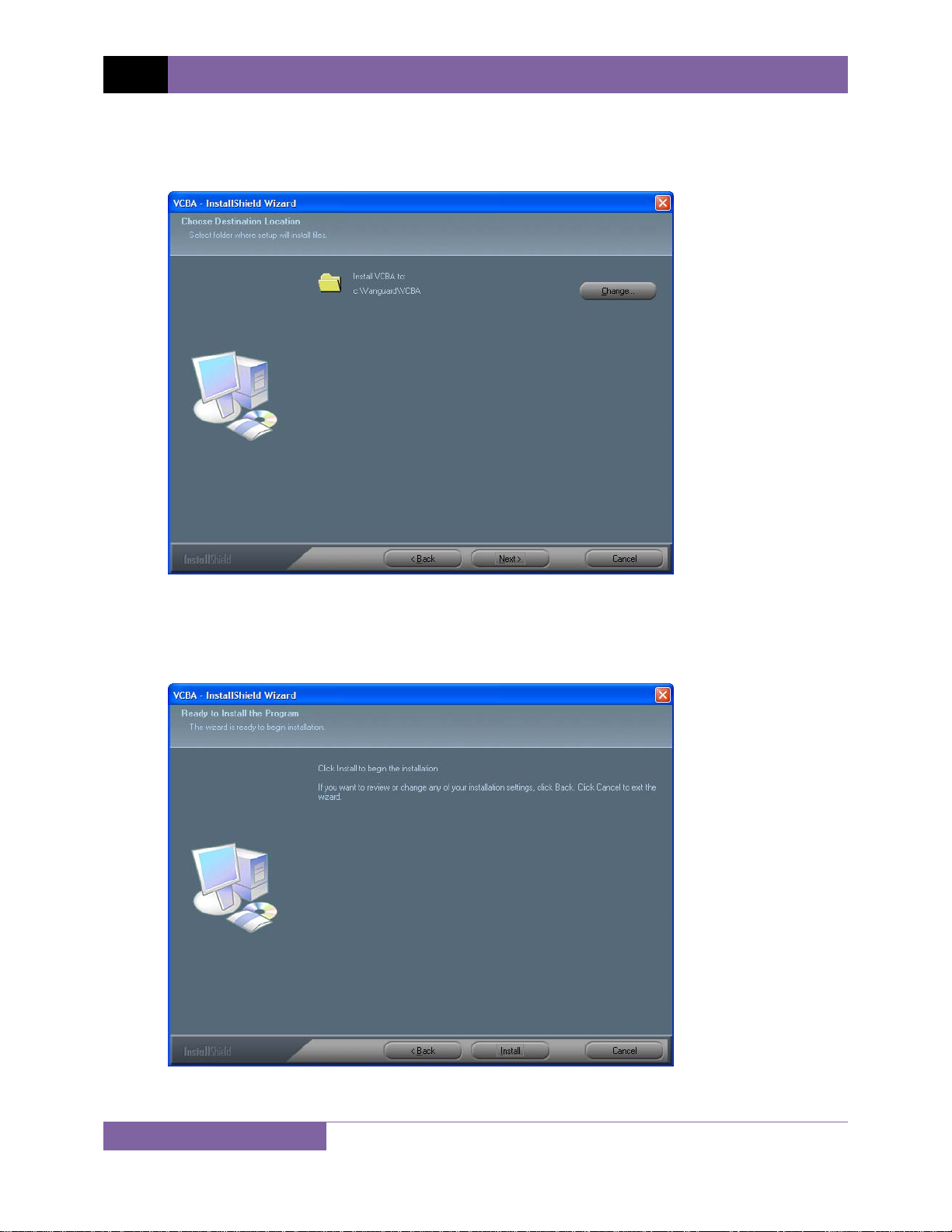
6. Click on the “Next” button to continue. The following screen will be displayed showing
the location on your hard drive where the software will be installed
(C:\vanguard\VCBA):
7. You may choose a different installation location by clicking on the “Change…” button
and then browsing to the location on your hard drive where you would like to install the
software. If you would like to install the software in the default location, click on the
“Next” button to continue. The following screen will be displayed:
4
Page 7
VCBA VERSION 10.xx SOFTWARE MANUAL REV 2
8. Click on the “Install” button. The InstallShield Wizard will copy files to your hard drive.
The following screen will be displayed once the software has been successfully installed:
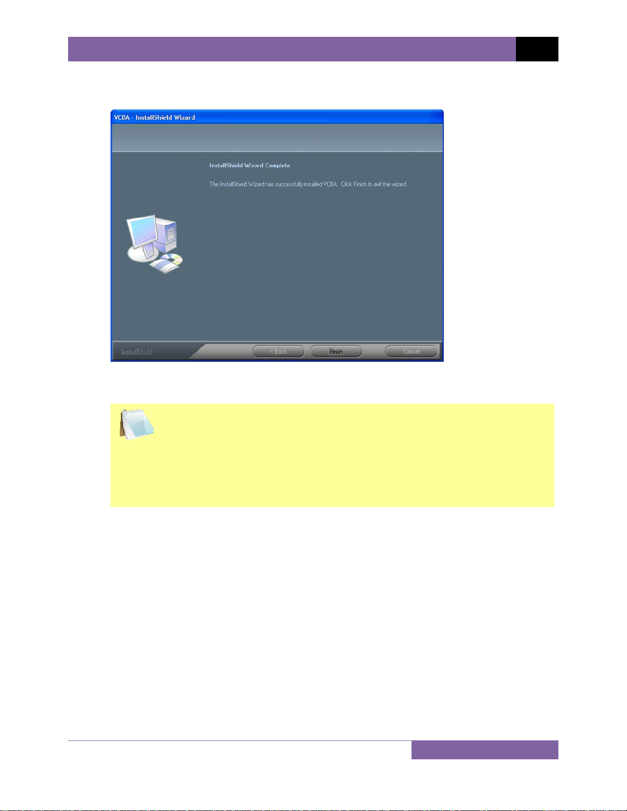
9. Click on the “Finish” button to close the InstallShield Wizard and complete the
installation process.
• The installation program will create two sub-folders, “shots” and
NOTES
“setup”, in the main installation folder. By default all test records will be
stored in the “shots” folder and all test plans will be stored in the
“setup” folder.
• You can later change the default test record and test plan storage
locations. Please see section 3.4 for details.
5
Page 8
REV 2 VCBA VERSION 10.xx SOFTWARE MANUAL
3.0 STARTING THE VCBA SOFTWARE
During the installation process, a Vanguard program group will be created under the All
Programs submenu in the Windows Start menu. To launch the VCBA software:
1. Click on the Windows “Start” menu button to open the Start Menu.
2. Click on the All Programs menu item.
3. Click on the Vanguard menu item.
4. Click on the VCBA menu item.
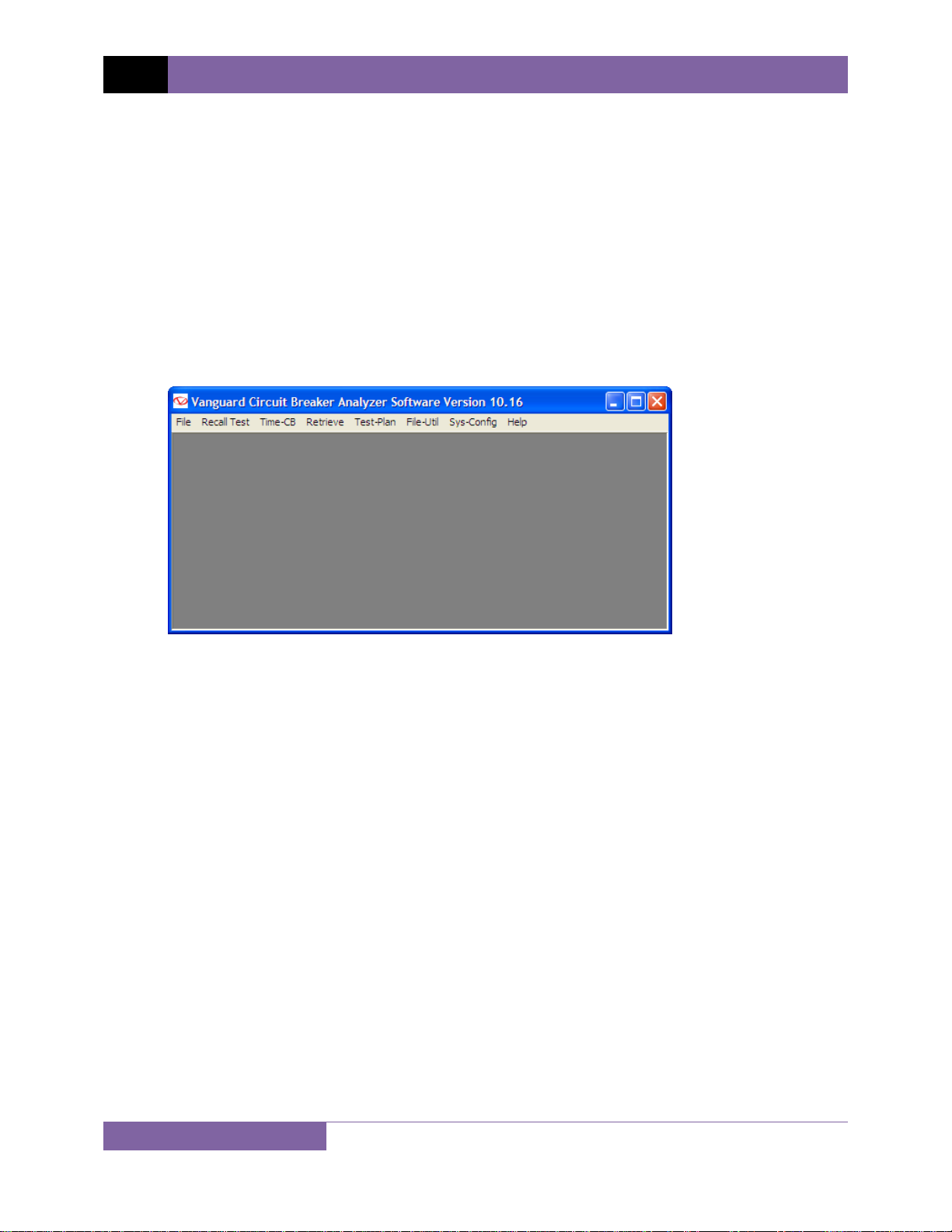
5. Click on the Launch vcba.exe menu item. The VCBA main application window will appear
as shown below:
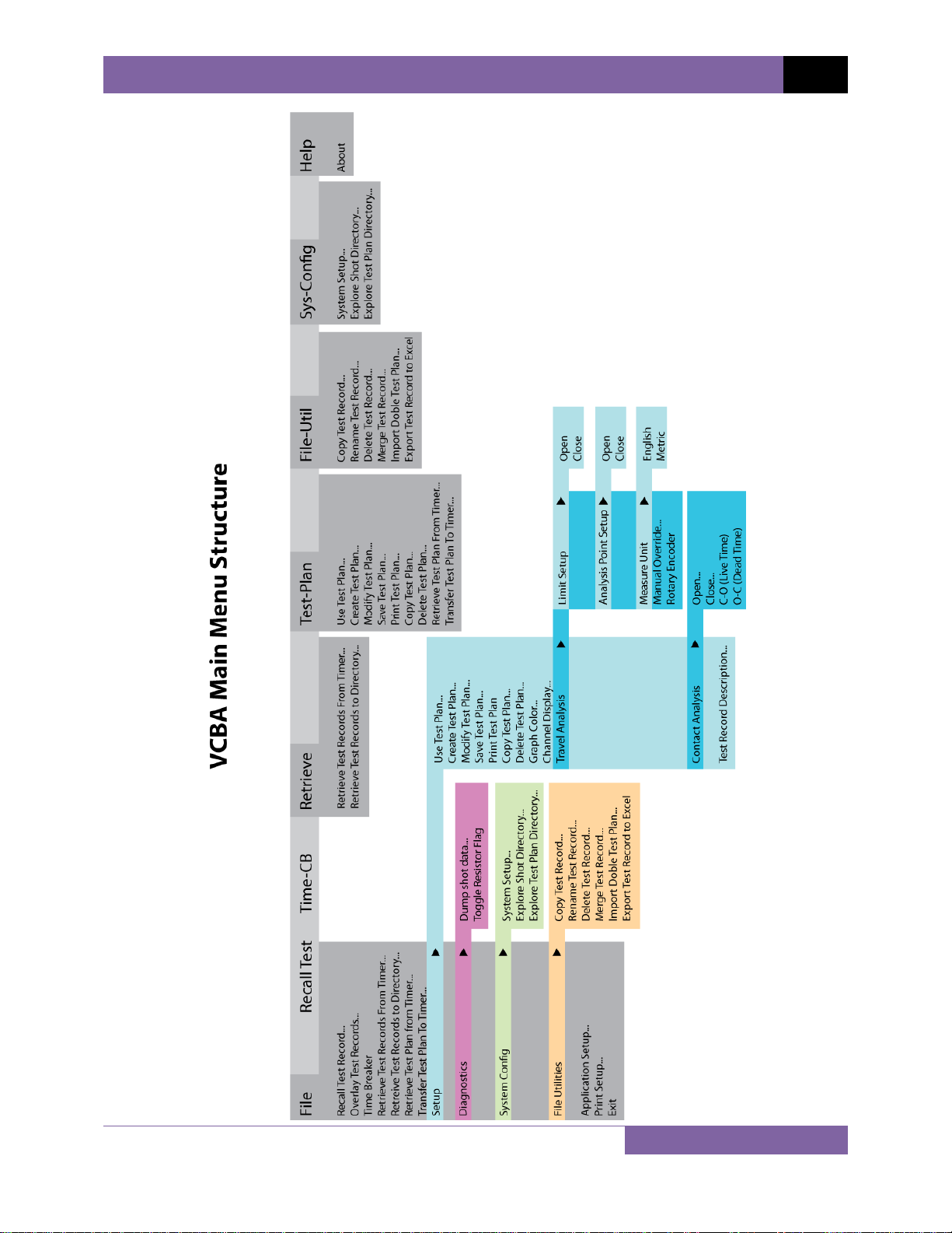
3.1 Main Menu Item Descriptions
The VCBA Main Menu bar features the following menus:
• File menu:
o Recall and overlay test records
o Transfer test records and test plans
o Configure system parameters and options
o Use various file utilities
• Recall Test: Recall test records from the PC hard drive for viewing
• Time CB: Perform a breaker timing test from the PC using a connected CB analyzer
• Retrieve: Retrieve test records from a CB analyzer
• Test-Plan: Create, use, modify, save, print, copy, delete, and transfer test plans
• File-Util: Copy, rename, delete, merge, and export test records
• Sys-Config: Configure system parameters
• Help: Display information about the VCBA software
6
Page 9
VCBA VERSION 10.xx SOFTWARE MANUAL REV 2
7
Page 10
REV 2 VCBA VERSION 10.xx SOFTWARE MANUAL
3.2 Enabling the Computer Interface
The Computer Interface Mode allows you to retrieve test records and test plans from a CB
analyzer and to transfer test plans to a CB analyzer. In this mode, tests can also be run on a CB
analyzer from the PC.
To enable the Computer Interface Mode:
1. Make sure the VCBA software is running on the PC.
2. Click on the Sys-Config menu and select System Setup… to configure the RS-232C
communication port. The following window will be displayed:
Click on the “Port:” drop down list and select the PC COM: port that the CB analyzer will
be connected to (COM1: to COM8: is supported). Click on the “Save” button, and then
click on the “OK” button. If you do not click on the “Save” button, any settings you
change will only stay active for the current session and will be reset the next time you
run the software.
3. Connect the CB analyzer to the PC via the RS-232C port and turn on the power.
4. Once the CB analyzer has gone through its start-up cycle, the main menu will be
displayed as shown:
1. TIME BRKR 03/24/09
2. GET RSLT
3. SET-UP
4. DIAGNOSTICS
Press the [3] key (SET-UP).
8
Page 11
VCBA VERSION 10.xx SOFTWARE MANUAL REV 2
5. The following screen will be displayed:
1. ANALYSIS POINTS
2. MEASUREMENT UNITS
3. SAVE / RESTORE
4. NEXT PAGE
Press the [4] key (NEXT PAGE).
6. The following screen will be displayed:
1. SHOT DESCRIPTION
2. COMPUTER ITF
3. SET CLOCK
4. SET PRINT MODE
Press the
[2] key (COMPUTER ITF).
7. The following screen will be displayed:
COMPUTER ITF MODE
“STOP” TO ABORT
The CB analyzer is now ready to communicate with the VCBA software.
If you experience any problems enabling the Computer Interface Mode:
1. Turn off both the PC and the CB analyzer.
2. Connect the CB analyzer to the PC via the RS-232C port.
3. Turn on the computer and run the VCBA software.
4. Follow steps 4-7 in the above section to put the CB analyzer in computer interface
mode.
9
Page 12
REV 2 VCBA VERSION 10.xx SOFTWARE MANUAL
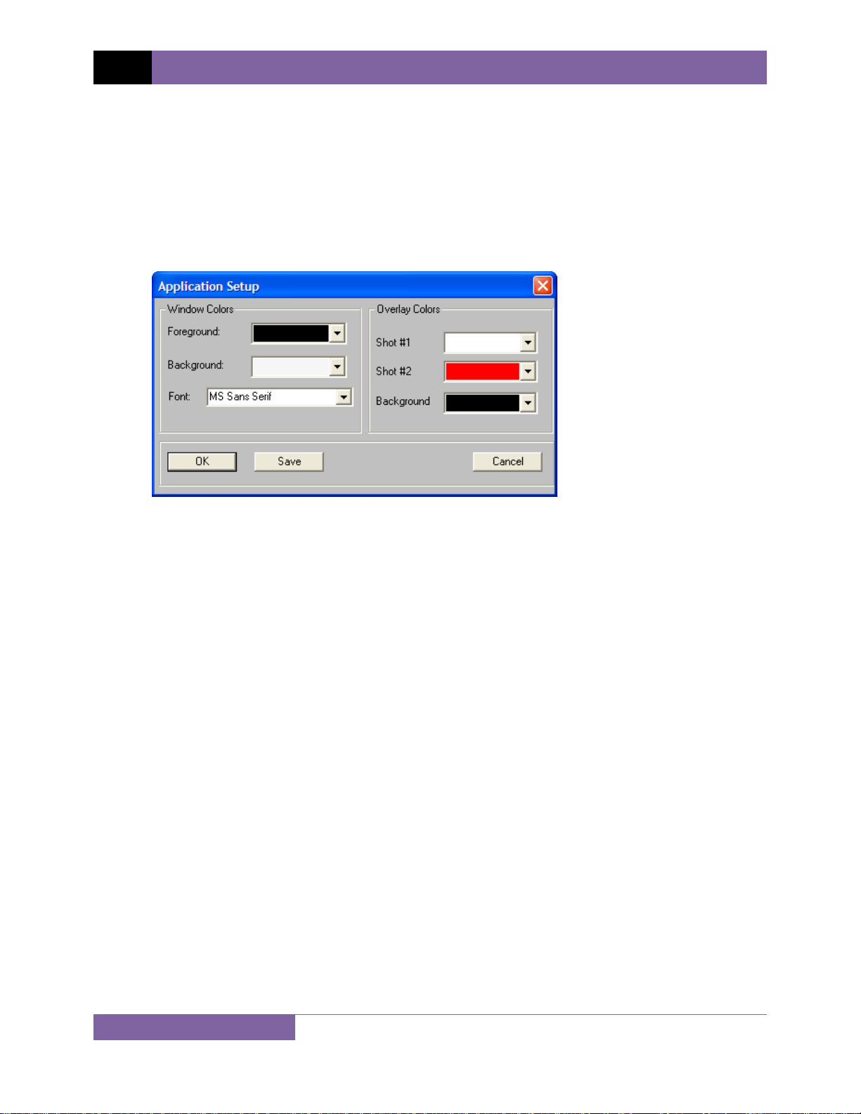
3.3 Application Setup
You can customize the VCBA’s window colors and the font used to display data. You can also
customize the colors used for the test record overlay graph (see section 4.11.4 for further
information about overlaying test records). To customize the interface and overlay graph
colors:
1. Click on the File menu and select Application Setup… The following window will be
displayed:
2. From the “Foreground:” drop down list in the “Window Colors” group, select the color
you would like to use for the foreground elements displayed on the screen.
3. From the “Background:” drop down list in the “Window Colors” group, select the color
you would like to use for the background elements displayed on the screen.
4. From the “Font:” drop down list in the “Window Colors” group, select the font you
would like to use for displaying information on the screen.
5. From the “Shot #1” drop down list in the “Overlay Colors” group, select the color you
would like to use for the Shot #1 trace when viewing test record overlay graphs.
6. From the “Shot #2” drop down list in the “Overlay Colors” group, select the color you
would like to use for the Shot #2 trace when viewing test record overlay graphs.
7. From the “Background” drop down list in the “Overlay Colors” group, select the
background color for the test record overlay graph.
8. Click on the “Save” button and then click on the “OK” button. If you do not click on the
“Save” button, any settings you change will only stay active for the current session and
will be reset the next time you run the software.
10
Page 13
VCBA VERSION 10.xx SOFTWARE MANUAL REV 2
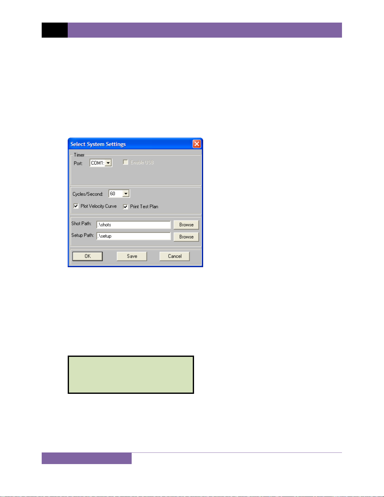
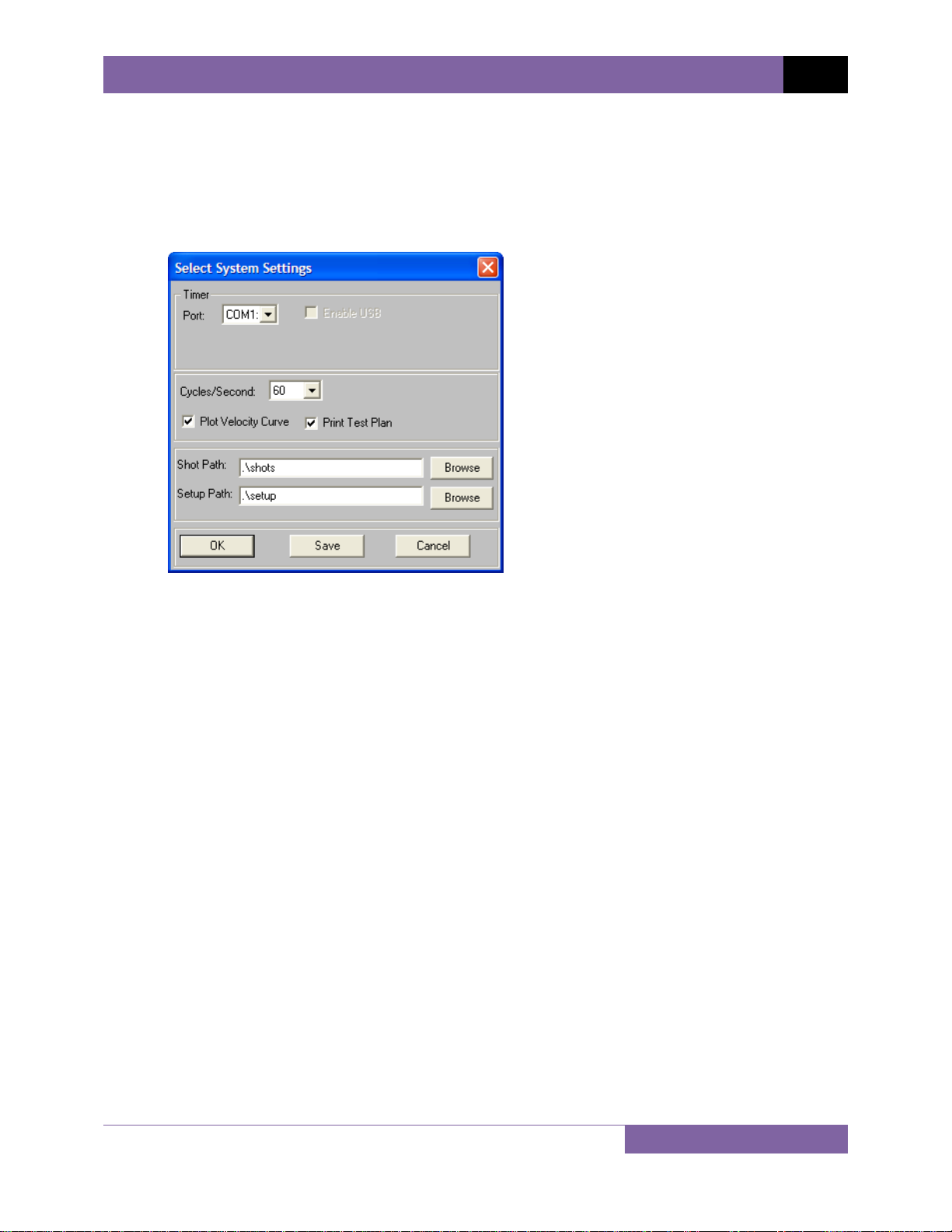
3.4 System Setup
To change the default system settings (such as the communication port, file location paths, etc):
1. From the File menu, click on System Config and then select System Setup…
(Alternatively, if no test records or test plans are open, you can click on the Sys-Config
menu and select System Setup…). The following window will be displayed:
2. Click on the “Port:” drop down list and select the PC COM: port that the CB analyzer is
connected to.
3. Select the appropriate frequency setting from the “Cycles/Second:” drop down list.
4. If you would like to have the velocity curve plotted on the graphic results screen and on
the test record printout, check the “Plot Velocity Curve” checkbox by clicking on it.
Please see section 4.11.1 for further information.
5. If you would like to print the test plan when a tabulated test record is printed, check the
“Print Test Plan” checkbox by clicking on it. Please see section 4.10.2 for further
information.
6. To change the default location where test records are stored, click on the “Browse”
button to the right of the “Shot Path:” input field. Browse to the new location and click
on the “OK” button.
7. To change the default location where test plans are stored, click on the “Browse” button
to the right of the “Setup Path:” input field. Browse to the new location and click on the
“OK” button.
8. Click on the “Save” button and then click on the “OK” button. If you do not click on the
“Save” button, any settings you change will only stay active for the current session and
will be reset the next time you run the software.
11
Page 14

REV 2 VCBA VERSION 10.xx SOFTWARE MANUAL
4.0 WORKING WITH TEST RECORDS
The VCBA software can be used to retrieve test records from the CB analyzer or from the PC
hard drive. Once a test record is retrieved, you can change the record header settings, print the
test record, change velocity calculation points, change circuit breaker test parameters, and save
the record to the hard drive.
4.1 Exploring the Test Records Directory
You can access the default test records directory (please see section 3.4 for information on how
to set the default test record directory) either via Windows Explorer or from within the VCBA
software. To open the test records directory:
1. From the File menu, click on System Config and then select Explore Shot Directory… The
default test record directory will be opened in Windows Explorer.
2. Use standard Windows Explorer commands to organize, rename, copy, or delete the
test record files. You can also create folders in this directory to logically organize the test
records.
4.2 Retrieving Test Records From a CB Analyzer
There are two ways to retrieve test records from a CB analyzer’s Flash EEPROM. The first
method is to click on the Retrieve menu and select Retrieve Test Records From Timer…
Alternatively, you can click on the File menu and select Retrieve Test Records
From Timer…
NOTE
The second method is to click on the Retrieve menu and select Retrieve Test Records to a
Directory…
Alternatively, you can click on the File menu and select Retrieve Test Records to a
Directory…
NOTE
Both methods are described in detail below.
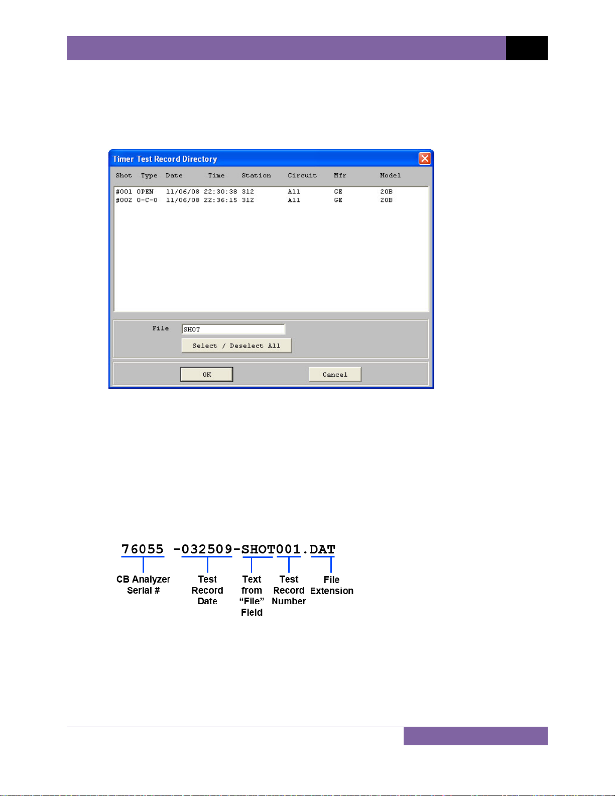
4.2.1. Retrieve Test Records From Timer
The Retrieve Test Records From Timer… option from the Retrieve or File menu can be used to
retrieve one or more records from a CB analyzer. When a record is retrieved, it is automatically
saved to the PC hard drive in the default “shots” folder.
You can change the location of the “shots” folder. Please see section 3.4 for
further information.
NOTE
1. Make sure the VCBA software is running. Connect the CB analyzer to the PC via the RS-
232C port and turn on the power.
12
Page 15
VCBA VERSION 10.xx SOFTWARE MANUAL REV 2
2. Put the CB analyzer in Computer Interface Mode. Please see section 3.2 for details.
3. From the Retrieve or File menu select Retrieve Test Records From Timer…
4. A window will appear listing a directory of all the test records stored in the CB analyzer’s
memory:
5. You can select a shot to be retrieved by clicking on the shot number. The selected
record will be highlighted. You may select multiple records by holding down the [CTRL]
key and clicking on the shot numbers. All selected records will be highlighted. You may
de-select a selected record by holding down the [CTRL] key and clicking on the selected
shot number a second time. If you would like to select all test records, click on the
“Select / Deselect All” button.
6. The “File” input field allows you to enter a word that will be used as part of the file
name for the stored record on the PC hard drive. When a test record is retrieved from a
CB analyzer and stored on the hard drive, the file name is in the following format:
So if you would like the file name to be “76055 -032509-TEST001.DAT”, enter the word
TEST in the “File” input field.
7. Click on the “OK” button to start retrieving the selected test records.
13
Page 16
REV 2 VCBA VERSION 10.xx SOFTWARE MANUAL
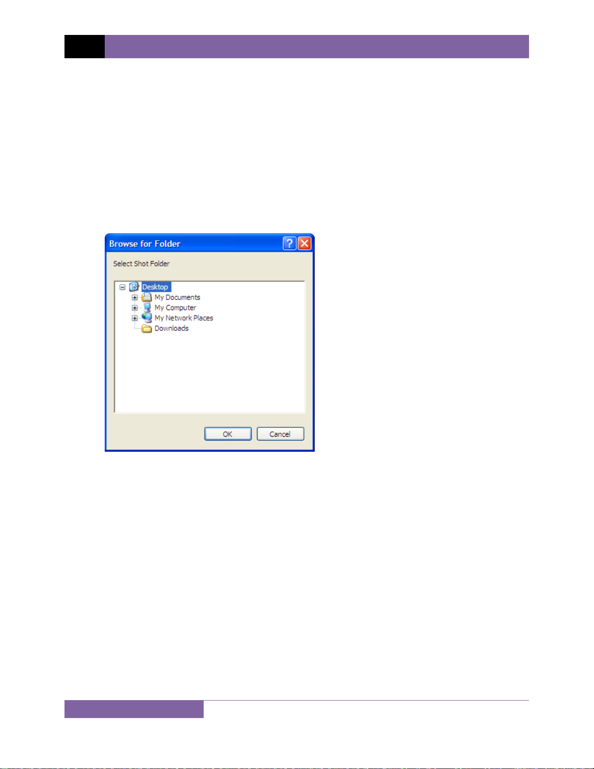
4.2.2. Retrieve Test Records to Directory
The Retrieve Test Records to Directory… option from the Retrieve or File menu can be used to
retrieve one or more records from a CB analyzer to a specific directory on the PC hard drive.
1. Make sure the VCBA software is running. Connect the CB analyzer to the PC via the RS-
232C port and turn on the power.
2. Put the CB analyzer in Computer Interface Mode. Please see section 3.2 for details.
3. From the Retrieve or File menu select Retrieve Test Records to Directory…
4. The following window will appear allowing you to select the location where you would
like to store the retrieved test records:
Browse to the folder where you would like the retrieved records to be stored. Click on
the folder name and then click on the “OK” button.
5. Continue to step 4 from section 4.2.1.
14
Page 17
VCBA VERSION 10.xx SOFTWARE MANUAL REV 2
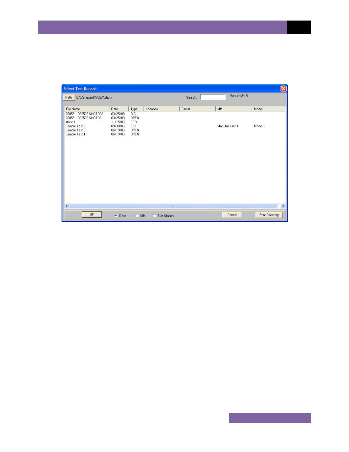
4.3 Recalling Test Records From the PC Har d Drive
Test records stored on the PC hard drive can be recalled using the steps below:
1. Click on the Recall Test menu (or click on the File menu and select Recall Test Record…).
The following window will be displayed:
• The top left section of the window displays the name of the directory where the test
records are being retrieved from. If you wish to retrieve records from a different
directory, click on the “Path” button and browse to the folder containing the test
records.
• The top right section of the window displays the total number of shots stored in the
current directory.
• You can sort the records by Date, Manufacturer, or Sub Station name. To change the
sort order, click on the corresponding radio box at the bottom of the window. For
example, if you would like the records to be sorted by Substation, click on the “Sub
Station” radio box at the bottom of the window.
• If you would like to print the current directory listing, click on the “Print Directory”
button at the bottom of the window. Select the printer to print to and click on the
“OK” button.
15
Page 18
REV 2 VCBA VERSION 10.xx SOFTWARE MANUAL
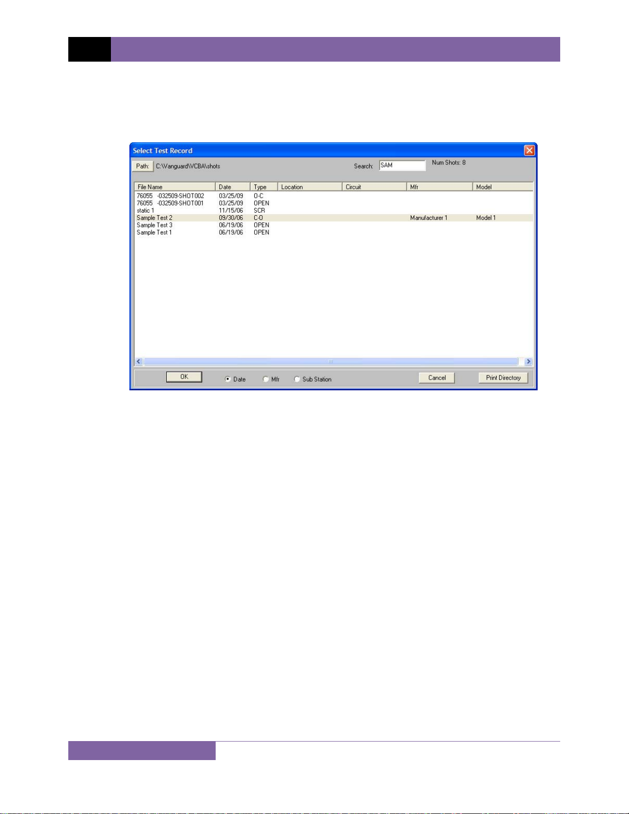
• You can also search for a particular record. You can start typing in the “Search” input
field and it will actively highlight the first matching file name. For example, in the
listing below, typing SAM in the “Search” field will highlight the “Sample Test 2” file
name as shown below:
2. Click on the file name you would like to retrieve and click the “OK” button. The test
record will be loaded and the tabulated test results will be displayed (please see section
4.10 for details).
16
Page 19
VCBA VERSION 10.xx SOFTWARE MANUAL REV 2
4.4 Saving a Test Record
4.4.1. Saving a Test Record with its Original File Name
1. To save a test record with its original file name, click on the Save-Test menu and select
Overwrite.
2. The test record will be saved with its original file name.
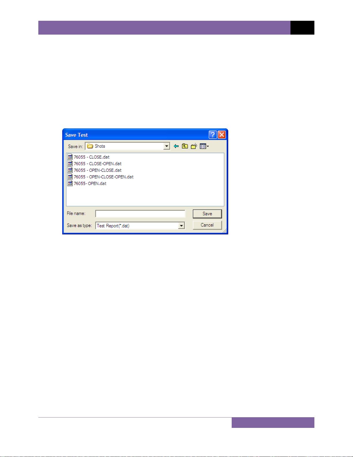
4.4.2. Saving a Test Record with a Different File Name
1. To save a test record with a different file name, click on the Save-Test menu and select
Save As. The following window will be displayed:
2. Browse to the folder where you would like to save the test record.
3. Enter the file name in the “File name:” input field.
4. Click on the “Save” button.
5. The test record will be saved with the new file name.
17
Page 20
REV 2 VCBA VERSION 10.xx SOFTWARE MANUAL
4.5 Copying a Test Record
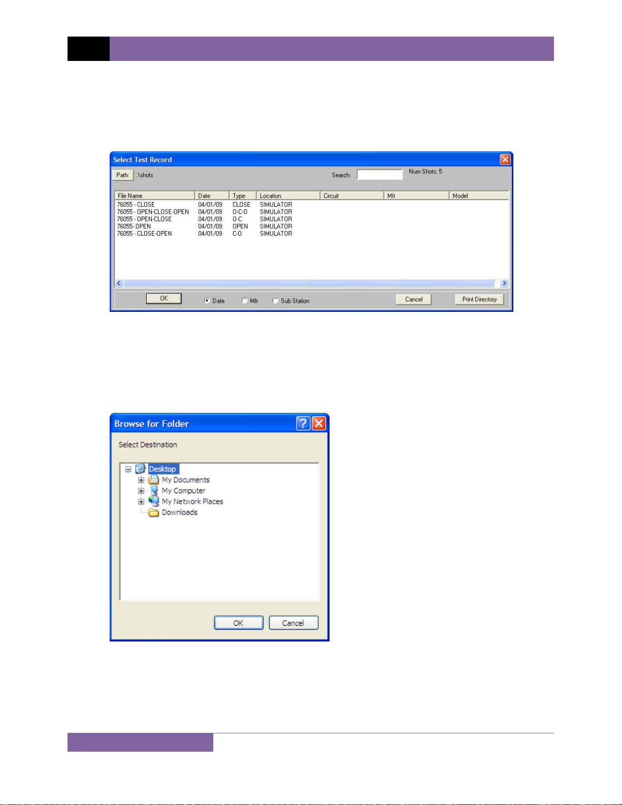
To copy a test record from one location on the PC hard drive to another location:
1. From the File menu, click on File Utilities and then select Copy Test Record… The
following window will be displayed:
2. If the test record you would like to copy is not in the current directory, click on the
“Path” button at the top of the window and browse to the directory containing the file.
Once you have located the test record to be copied, click on the file name. You may
select additional test records by holding down the [CTRL] key and clicking on each
subsequent file name. Once you have selected the test record(s) to be copied, click on
the “OK” button. The following window will be displayed:
3. Browse to the folder where you would like the test record to be copied to, and then
click on the “OK” button. The test record will be copied to this folder with the same file
name as the original.
18
Page 21
VCBA VERSION 10.xx SOFTWARE MANUAL REV 2
4.6 Renaming a Test Record
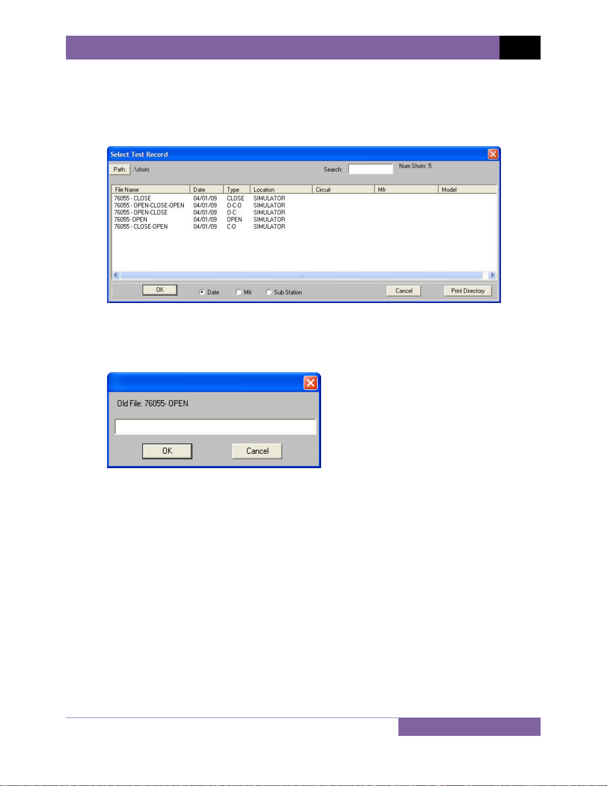
To rename a test record stored on the PC hard drive:
1. From the File menu, click on File Utilities and then select Rename Test Record… The
following window will be displayed:
2. If the test record you would like to rename is not in the current directory, click on the
“Path” button at the top of the window and browse to the directory containing the file.
Once you have located the test record to be renamed, click on the file name and then
click on the “OK” button. The following dialog box will be displayed:
3. Enter the new file name for the test record and click on the “OK” button. The test record
will be renamed with the new file name.
19
Page 22
REV 2 VCBA VERSION 10.xx SOFTWARE MANUAL
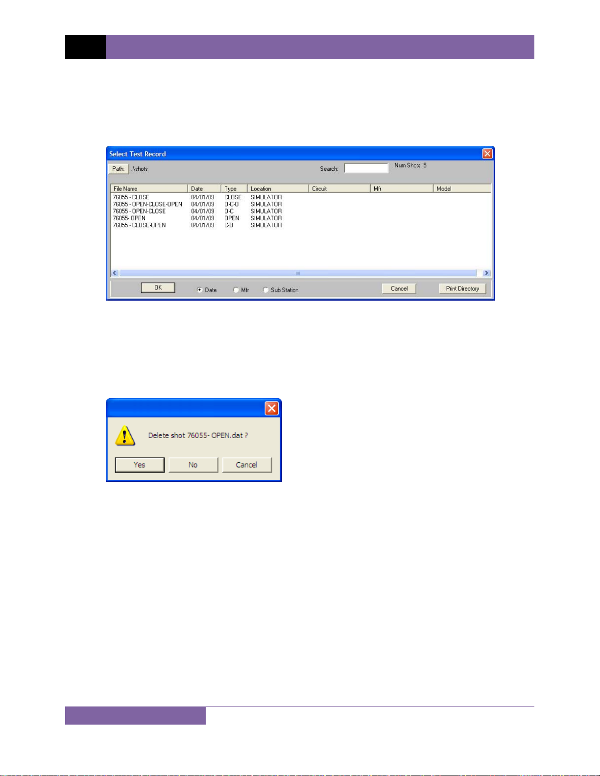
4.7 Deleting a Test Record
To delete a test record from the PC hard drive:
1. From the File menu, click on File Utilities and then select Delete Test Record… The
following window will be displayed:
2. If the test record you would like to delete is not in the current directory, click on the
“Path” button at the top of the window and browse to the directory containing the file.
Once you have located the test record to be deleted, click on the file name. You may
select additional test records by holding down the [CTRL] key and clicking on each
subsequent file name. Once you have selected the test record(s) to be deleted, click on
the “OK” button. The following window will be displayed:
3. Click on the “Yes” button to confirm the deletion of the test record. If you do not want
to delete the test record, click on the “No” or “Cancel” button.
20
Page 23
VCBA VERSION 10.xx SOFTWARE MANUAL REV 2
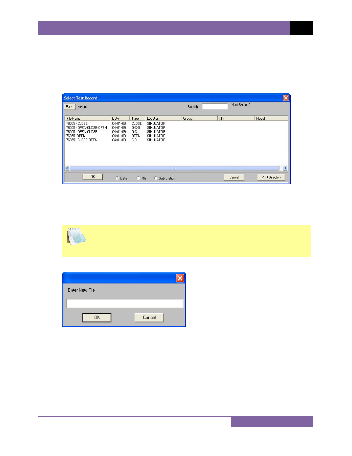
4.8 Merging Test Records
You can merge two test records to create a single test record. For example, you can combine
two 6-channel timing shots to create a 12-channel timing shot. To merge two test records:
1. From the File menu, click on File Utilities and then select Merge Test Record… The
following window will be displayed:
2. You can click on the “Path” button to browse to the directory containing the test
records to be merged. Once you have located the test records, click on the first file
name to be merged and then hold down the [CTRL] key and click on the second file
name. Then click on the “OK” button.
Both test records must be of the same type. For example, you cannot merge
a CLOSE type test record with an OPEN type test record.
NOTE
The following dialog box will be displayed:
3. Enter the file name for the new merged test record and then click on the “OK” button.
The data from the two source test records will be merged and saved as the new file
name. The two source test records will not be modified in any way.
21
Page 24
REV 2 VCBA VERSION 10.xx SOFTWARE MANUAL
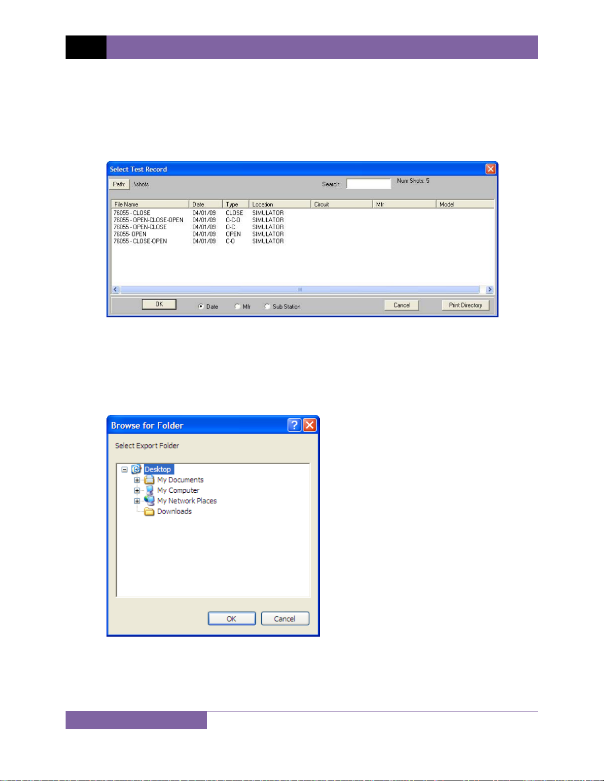
4.9 Exporting a Test Record in Microsoft® Excel® Format
You can export a test record in Microsoft® Excel® format. To export a test record in Excel®
format:
1. From the File menu, click on File Utilities and then select Export Test Record to Excel.
The following window will be displayed:
2. If the test record you would like to export is not in the current directory, click on the
“Path” button at the top of the window and browse to the directory containing the file.
Once you have located the test record to be exported, click on the file name. You may
select additional test records by holding down the [CTRL] key and clicking on each
subsequent file name. Once you have selected the test record(s) to be exported, click on
the “OK” button. The following window will be displayed:
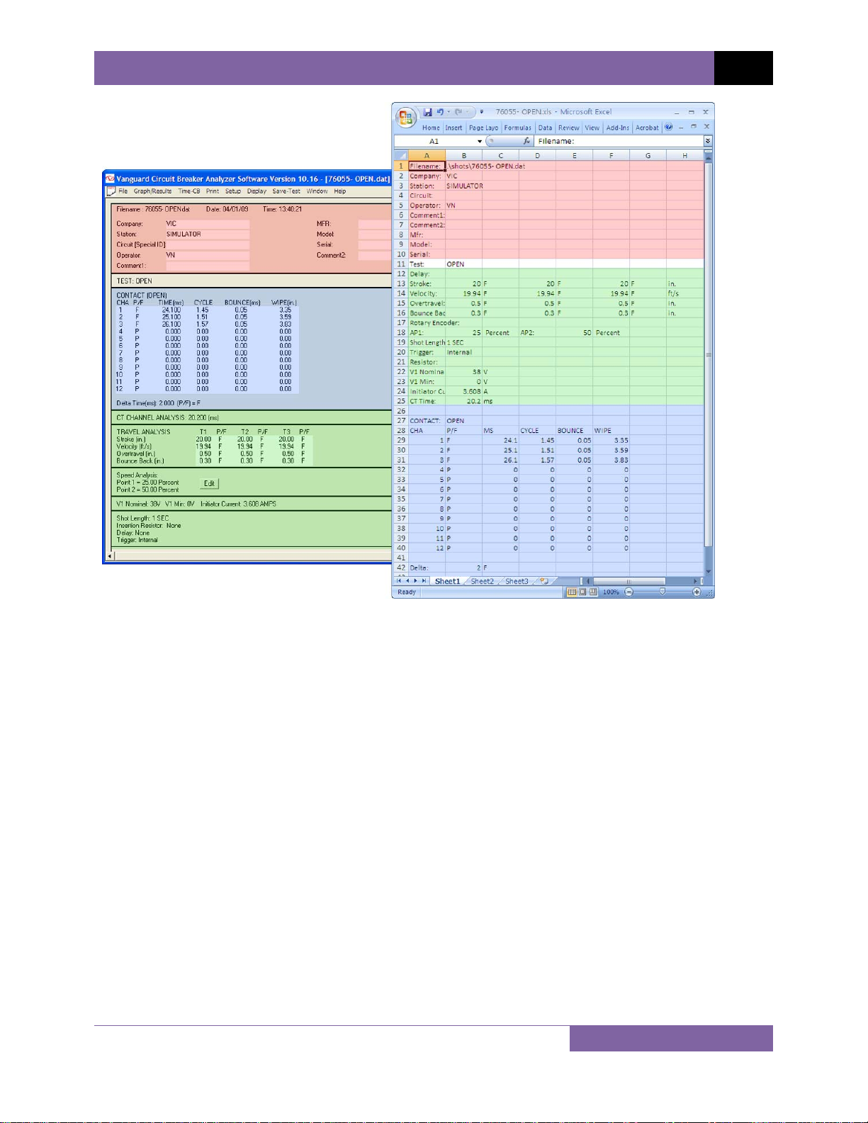
3. Browse to the folder where you would like the Excel
“OK” button. Figure 1 shows a test record in the VCBA software compared with the
exported data in Excel®.
22
®
files to be saved and click on the
Page 25
VCBA VERSION 10.xx SOFTWARE MANUAL REV 2
Figure 1 Test Record in VCBA Software and Microsoft Excel
(corresponding sections highlighted in color)
23
Page 26

REV 2 VCBA VERSION 10.xx SOFTWARE MANUAL
4.10 Viewing and Working with Tabulated Test Results
Once a test record has been retrieved (see sections 4.2 and 4.3 for instructions), the record
details will be displayed as shown:
The menus on the menu bar will also change to provide additional options relevant to working
with a test record.
You can edit the test record header information (such as Company, Station, etc.)
by entering data in the corresponding fields at the top of the screen.
NOTE
24
Page 27

VCBA VERSION 10.xx SOFTWARE MANUAL REV 2
4.10.1. Viewing the Test Plan for a Test Record
You can view the test plan for the test record by pressing the [Page Down] key on the
keyboard. Below is an example of the test plan screen:
You can return to the test record details by pressing the [Page Up] key.
You may edit any of the test plan parameters by typing a new value in the input field. Press the
[ENTER] or [TAB] key after entering a value.
Open and Close analysis points can also be changed by clicking on the “Edit” button to the right
of each corresponding label.
The Manual Stroke Override can also be changed by clicking on the “Edit” button to the right of
the label.
25
Page 28

REV 2 VCBA VERSION 10.xx SOFTWARE MANUAL
• When a test record is saved, the test plan is saved along with it. You may also
NOTES
save the test plan as a separate test plan file. Please see section 5.6 for
further information.
• The Contact Analysis values can also be changed from the menu system.
From the File menu, click on Setup and then click on Contact Analysis. Then
select the option you would like to edit. If the contact analysis parameters
are changed, the Pass/Fail results will be updated based on the new
parameters.
• The Travel Analysis values can also be changed from the menu system. From
the File menu, click on Setup and then click on Travel Analysis. Then select
the option you would like to edit. If the travel analysis values are changed,
the Pass/Fail results will be updated based on the new parameters.
• If the Open and Close analysis points are changed, the VCBA software will re-
calculate the circuit breaker velocity and update the Pass/Fail results.
26
Page 29

VCBA VERSION 10.xx SOFTWARE MANUAL REV 2
4.10.2. Printing Tabulated Test Results
To print the tabulated test results:
1. Retrieve the test record that you would like to print (See sections 4.2 and 4.3).
2. If you would like to print the test parameters with the tabulated test results:
• From the File menu click on System Config and then click on System Setup…
The following window will appear:
Make sure the “Print Test Plan” checkbox is checked. If it is not checked, click on
the checkbox and a check mark will appear.
• Click on the “OK” button.
3. Click on the Print menu and select Print Tabulated.
4. Select the printer that you would like to print to and click on the “OK” button. The
tabulated test results will be printed on the selected printer. A typical CB tabulated test
report printout is shown in Figure 2. A typical CB test parameters printout is shown in
Figure 3.
27
Page 30

REV 2 VCBA VERSION 10.xx SOFTWARE MANUAL
Figure 2 Typical CB Tabulated Test Report
28
Page 31

VCBA VERSION 10.xx SOFTWARE MANUAL REV 2
Figure 3 Typical CB Test Parameters
29
Page 32

REV 2 VCBA VERSION 10.xx SOFTWARE MANUAL
)
)
)
)
)
4.11 Viewing and Working with Graphic Test Results
To display graphic results of a timing record:
1. Retrieve the test record that you would like to view (See sections 4.2 and 4.3).
2. Click on the Graph/Results menu. The graphic results will be displayed as shown in
Figure 4. Click on the Graph/Results menu again to return to the tabulated test results
screen. Alternatively, you can press [CTRL]+[G] to toggle between the two views.
3. There are a total of 6 graphic results pages. Press the [Page Down] key to view the next
page. Press the [Page Up] key to view the previous page.
Contact Channel 1 (C1
Contact Channel 2 (C2
Contact Channel 3 (C3
Travel Curve
Figure 4 Graphic Test Results
• Contact channel ID’s are shown as C1, C2, and C3 on the left side of
NOTES
the graph. Up to 12 contact channels can be displayed on one graphic
report page.
• Voltage monitoring channel V1 is shown below contact channel C3.
• Coil initiate current is shown as I1.
Voltage Monitoring Channel 1 (V1
Coil Initiate Current (I1
30
Page 33

VCBA VERSION 10.xx SOFTWARE MANUAL REV 2
4.11.1. Toggling the Display of the Velocity Curve
To plot the velocity curve on the graphic test results:
1. From the File menu click on System Config and then click on System Setup… The
following window will be displayed:
If the “Plot Velocity Curve” checkbox is not already checked, click on the checkbox and a
check mark will appear. Click on the “Save” button, and then click on the “OK” button. If
you do not click on the “Save” button, any settings you change will only stay active for
the current session and will be reset the next time you run the software.
2. Click on the Graph/Results menu and the graphic test results will be displayed and will
include the velocity curve as shown below:
Velocity Curve
31
Page 34

REV 2 VCBA VERSION 10.xx SOFTWARE MANUAL
If you do not want to display the velocity curve on the graphic test results:
1. From the File menu click on System Config and then click on System Setup… The
following window will be displayed:
If the “Plot Velocity Curve” checkbox is already checked, click on the checkbox to uncheck it. Click on the “Save” button, and then click on the “OK” button. If you do not
click on the “Save” button, any settings you change will only stay active for the current
session and will be reset the next time you run the software.
2. Click on the Graph/Results menu and the graphic test results will be displayed without
the velocity curve as shown below:
32
Page 35

VCBA VERSION 10.xx SOFTWARE MANUAL REV 2
4.11.2. Customizing the Items Displayed on the Graphic Results Screen
You can select which contact, travel, and voltage traces are displayed in the graphic test results.
To select the items to be displayed:
1. Retrieve the test record that you would like to view (See sections 4.2 and 4.3).
2. Click on the Graph/Results menu to display the graphic test results.
3. Click on the Display menu and select Channel Display… The following window will be
displayed:
4. You can customize what items are displayed on each page of the graphic results screen.
Select the page number you would like to customize from the “Page #” drop down list.
5. In each input box, enter the channel number for the item you would like to display. In
the example above, Contact Channels 1, 2, and 3 will be displayed on page 1 of the
graphic results screen along with Voltage Channel 1, Current Channel 1, and Travel
Channel 1. Be sure to enter 0 for all channels you do not want to display.
As another example, if you would like page 2 of the graphic results screen to show
contact channels 4, 5, and 6, click on the “Page #” drop down list and select page 2.
Then under the “Contact (1-24)” heading, enter 4, 5, and 6 in the first 3 boxes. Click on
the “OK” button. Page two of the graphic results screen will now show the traces for
contact channels 4, 5, and 6 while page one will display contact channels 1, 2, and 3.
6. Click on the “OK” button and the graphic test results screen will be updated with the
new settings.
33
Page 36

REV 2 VCBA VERSION 10.xx SOFTWARE MANUAL
4.11.3. Customizing the Graph Colors
The foreground and background color of each Contact, Travel, Current, and Voltage trace can
be customized. To change the trace colors:
1. Retrieve the test record that you would like to view (See sections 4.2 and 4.3).
2. Click on the Graph/Results menu to display the graphic test results
3. Click on the Display Menu and select Graph Color… The following window will be
displayed:
4. From the “Channel” drop down list, select the channel that you would like to set the
graph colors for. From the “Trace Color” drop down list, select the foreground color for
the selected channel. From the “Background” drop down list, select the background
color for the selected channel. You can repeat this process for each channel that you
would like to customize.
5. Select the graph type by clicking either on the “Analog” or “Digital” radio button.
A “Digital” graph type will display the contact trace as steps from open to
close. An “Analog” graph type will display the contact trace as an analog
NOTE
6. If you would like to apply the same color settings to all channels, click on the “Apply To
All” checkbox.
7. Click on the “OK” button and the graphic test results screen will be updated with the
new colors.
waveform.
34
Page 37

VCBA VERSION 10.xx SOFTWARE MANUAL REV 2
4.11.4. Overlaying Two Timing Shots
You can graphically compare two timing shots on the screen by overlaying them. This is a very
useful feature for viewing a circuit breaker’s operating condition. For example, test results from
before and after breaker maintenance can be overlaid and compared.
To graphically overlay two timing shots:
1. Click on the File menu and select Overlay Test Records… The following window will be
displayed:
2. If the test records are not located in the current path, click on the “Path” button at the
top left of the window and locate the folder on your computer containing the test
records you would like to overlay.
3. Select the first test record by clicking on the file name. Select the second test record by
holding down the [CTRL] key and then clicking on the file name. Both file names will be
highlighted.
35
Page 38

REV 2 VCBA VERSION 10.xx SOFTWARE MANUAL
4. Click on the “OK” button and the graphic test results will be displayed as shown below:
• Press the [Page Down] key to view the next page. Press the [Page Down]
key to view the previous page.
NOTES
5. If you would like to print the overlay graphs, click on the Print menu and select Print
Graphic. If you would like to print the tabulated test results for both test records, click
on the Print menu and select Print Tabulated.
• You can customize the test record overlay graph colors. Please see
section 3.3 for further information.
36
Page 39

VCBA VERSION 10.xx SOFTWARE MANUAL REV 2
4.11.5. Viewing a Graph Expansion
You can expand a portion of the graphic test results for more accurate analysis. For example, if
you want to view the graph from 0ms to 300ms:
1. Retrieve the test record that you would like to view (See sections 4.2 and 4.3).
2. Click on the Graph/Results menu to display the graphic test results.
3. Move the cursor over the graph area. A vertical hairline will appear at the cursor
location. Also, the bottom of the graph will display the text “T=xx.xx ms” indicating the
current location of the cursor. Move the cursor so that the vertical hairline is at 0ms and
the text at the bottom of the graph reads “T=0.00ms” as shown below:
NOTES
When you move the cursor over a point on the graph, the Stroke and
Velocity values are displayed above the graph, and the Time, Current, and
Voltage are displayed below the graph.
37
Page 40

REV 2 VCBA VERSION 10.xx SOFTWARE MANUAL
4. Hold down the left mouse button and drag the cursor to the right till the vertical hairline
is at 300ms and the text at the bottom of the graph reads “T=300.00 ms” as shown
below:
5. Release the mouse button and an expanded graph of the selected region will be
displayed as shown below:
6. You can further expand the expansion graph by using the steps above. The maximum
expansion that can be viewed is a range of 100ms.
38
Page 41

VCBA VERSION 10.xx SOFTWARE MANUAL REV 2
7. Click anywhere on the graph area to view the entire graph again.
• You can view an expansion of any of the graphic results pages. Simply
NOTES
press the [Page Up] and [Page Down] keys to view the desired graph
page, and then follow the steps above to view an expansion.
• You can also use the steps above to view an expansion of a graphic
overlay screen (see section 4.11.4 for further information about
overlaying timing shots)
39
Page 42

REV 2 VCBA VERSION 10.xx SOFTWARE MANUAL
4.11.6. Calculating the Average Velocity From the Graphic Test Results
When viewing the graphic test results, you can view the velocity value at any point by moving
the cursor over the point on the graph. The stroke and velocity value will be displayed at the
top of the screen. You can also calculate the average velocity between two points by using the
steps below:
1. Retrieve the test record that you would like to view (See sections 4.2 and 4.3).
2. Click on the Graph/Results menu to display the graphic test results.
3. Move the cursor to the first point on the travel curve. A vertical hairline will appear at
the cursor location as shown below:
40
Page 43

VCBA VERSION 10.xx SOFTWARE MANUAL REV 2
4. Hold down the RIGHT mouse button and drag the cursor to the second point on the
travel curve:
5. Release the mouse button and the average velocity between the selected two points (in
m/s or ft/s) will be displayed at the bottom of the screen:
Average Velocity
41
Page 44

REV 2 VCBA VERSION 10.xx SOFTWARE MANUAL
4.11.7. Manually Overriding Contact Time/Resistor Contact Time or Contact Wipe
You can override the calculated Contact Time, Resistor Time, or Contact Wipe readings in the
tabulated test results. This is a useful feature for situations where a manual calculation is
preferred. For example, in the figure below, the calculated CLOSE time for channel 2 can be
overridden with the preferred time:
To override the calculated CLOSE time with the preferred time for the above example:
1. Retrieve the test record that you would like to view (See sections 4.2 and 4.3). The
tabulated test results will be displayed.
42
Page 45

VCBA VERSION 10.xx SOFTWARE MANUAL REV 2
2. Click on the Graph/Results menu to display the graphic test results. Then move the
cursor to the preferred time that you would like to use as the override value. In this
example, the cursor is positioned at 206.60 ms as shown below (note that the time at
the cursor position will be displayed at the bottom of the graph as T = x.x ms):
3. Press the [F8] key. The following window will be displayed:
43
Page 46

REV 2 VCBA VERSION 10.xx SOFTWARE MANUAL
4. Click on the “Contact:” dropdown list to select the contact you would like to override
the values for. For the example above, we would like to override the Close value for
contact 2, so we will select 2 from the dropdown list. The values for contact 2 will be
displayed as shown:
5. Click on the “Enable” checkbox next to each field that you would like to override with
the value from the cursor position. The value from the cursor position will appear in the
input area to the right of the calculated value. In this case, we would like to override the
Close value, so we will click on the “Enable” checkbox to the right of the input area.
Once enabled, the value from the cursor position will be inserted in the input area as
shown:
44
Page 47

VCBA VERSION 10.xx SOFTWARE MANUAL REV 2
6. Click on the “OK” button. The override value will be inserted in the tabulated test results
as shown:
The above method works well for simple tests such as an OPEN or CLOSE test. For more
complex situations such as a CLOSE-OPEN test with an insertion resistor, you can manually
input the override values. To manually input the override values:
1. Retrieve the test record that you would like to view (See sections 4.2 and 4.3). The
tabulated test results will be displayed.
2. Press the [F8] key in either the tabulated results view or the graphic results view.
3. The “Contact Override” window will be displayed as in the previous example above.
Select the contact number from the “Contact:” dropdown list.
4. Click on the “Enable” checkbox next to each value you would like to override for the
selected contact, and then enter the override value in the input area to the left of the
checkbox.
5. Click on the “OK” button and all enabled override values will be inserted in the
tabulated test results.
45
Page 48

REV 2 VCBA VERSION 10.xx SOFTWARE MANUAL
4.11.8. Printing the Graphic Test Results
To print the graphic test results:
1. While viewing the tabulated or graphics test results of a test record, click on the Print
menu and select Print Graphic.
2. Select the printer you would like to print to and click on the “OK” button. All graphic test
results pages will be printed. A typical graphic results printout is shown in Figure 5
below.
Figure 5 Typical Graphic Results Printout
NOTES
46
• The printout will have the same expansion scale as the scale displayed
on the screen, so if you were viewing an expansion, the expansion
graph will be printed.
• If you had checked the “Plot Velocity Curve” checkbox in the System
Settings dialog box, the printout will include the Velocity Curve. Please
see section 4.11.1 for further information on how to change this
setting.
• Any customizations made to the graphic display (see sections 4.11.1,
4.11.2, and 4.11.3) will also apply to the printout. However, the
background color of the printout will always be white.
Page 49

VCBA VERSION 10.xx SOFTWARE MANUAL REV 2
4.12 Test Record Diagnostic Tools
4.12.1. Viewing Raw Shot Data
The VCBA software has the ability to view the raw test record data. To view a dump of this data:
1. Retrieve the test record that you would like to view (See sections 4.2 and 4.3).
2. From the File menu, click on Diagnostics and then select Dump Shot Data… The
following window will be displayed:
3. You can browse the raw shot data by clicking on the navigation buttons at the bottom of
the window. Click on the “Close” button to close the window.
47
Page 50

REV 2 VCBA VERSION 10.xx SOFTWARE MANUAL
4.12.2. Toggling the Resistor Flag
When performing a timing test on a circuit breaker with an insertion resistor, it’s important to
select the correct resistance value at the time the test is performed (please see section 6.0 for
information on how to perform timing tests). If this value is not entered for some reason,
incorrect test results may be obtained. However, this can be corrected using the VCBA
software. To set the resistor value for a test record:
1. Retrieve the test record that you would like to view (See sections 4.2 and 4.3).
2. From the File menu, click on Diagnostics and then select Toggle Resistor Flag. The
following window will be displayed:
3. Select the insertion resistor value and click on the “OK” button. The VCBA software will
calculate the main contact time and the resistor contact time based on the resistance
value provided. The tabulated test results will be updated with the correct calculated
values.
To permanently apply the changes, be sure to save the test record after
toggling the resistor flag. Please see section 4.4 for further information on
NOTES
how to save test records.
48
Page 51

VCBA VERSION 10.xx SOFTWARE MANUAL REV 2
5.0 WORKING WITH TEST PLANS
A circuit breaker test plan is comprised of all circuit-breaker performance specifications (stroke,
velocity, and contact time). A test plan can be used to test a circuit breaker. When used with a
test record, a Pass/Fail report is generated by comparing the actual performance of the breaker
with the specifications in the stored test plan. Test plans can be easily created with the VCBA
software and can be stored on the hard drive or transferred to a CB analyzer.
5.1 Exploring the Test Plans Directory
You can access the default test plans directory (please see section 3.4 for information on how
to set the default test plan directory) either via Windows Explorer or from within the VCBA
software. To open the test plans directory:
1. From the File menu, click on System Config and then select Explore Test Plan Directory…
The default test plans directory will be opened in Windows Explorer.
2. Use standard Windows Explorer commands to organize, rename, copy, or delete the
test plan files. You can also create folders in this directory to logically organize the test
plans.
5.2 Creating a Circuit Breaker Test Plan
To create a circuit breaker test plan:
1. Close any open test plans or test records.
2. Click on the Test-Plan menu and select Create Test Plan… The following window will be
displayed:
3. Click on each input field and enter the relevant header data for each field. Two
comment fields are also provided for any other relevant information. Click on the “OK”
button. The following window will be displayed:
49
Page 52

REV 2 VCBA VERSION 10.xx SOFTWARE MANUAL
4. This dialog box is used to define the Open Contact Analysis parameters. Enter the
Contact Low, Contact High, Contact Delta, Resistor On Low, Resistor On High, and
Resistor On Delta times (in milli-seconds) in each corresponding field.
• Contact Low is the fastest Open time of the circuit breaker main
NOTES
contacts.
• Contact High is the slowest Open time of the circuit breaker main
contacts.
• Contact Delta, also known as Contact Spread, is the maximum time
between the fastest and slowest contact time.
• Resistor On Low is the fastest Open time of the circuit breaker
insertion-resistor contacts.
• Resistor On High is the slowest Open Time of the circuit-breaker
insertion-resistor contacts.
• Resistor On Delta is the maximum time between the fastest and
slowest resistor contact time.
• Up to 20 characters can be entered in the Comment field.
50
Page 53

VCBA VERSION 10.xx SOFTWARE MANUAL REV 2
After entering all the values, click on the “OK” button. The following window will be
displayed:
5. This dialog box is used to define the Close Contact Analysis parameters. Enter the
Contact Low, Contact High, Contact Delta, Resistor On Low, Resistor On High, and
Resistor On Delta times (in milli-seconds) in each corresponding field.
51
Page 54

REV 2 VCBA VERSION 10.xx SOFTWARE MANUAL
• Contact Low is the fastest Close time of the circuit breaker main
NOTES
After entering all the values, click on the “OK” button. The following window will be
displayed:
contacts.
• Contact High is the slowest Close time of the circuit breaker main
contacts.
• Contact Delta, also known as Contact Spread, is the maximum time
between the fastest and slowest contact time.
• Resistor On Low is the fastest Close time of the circuit breaker insertion
resistor contacts.
• Resistor On High is the slowest Close time of the circuit breaker
insertion resistor contacts.
• Resistor On Delta is the maximum time between the fastest and the
slowest resistor contact time.
• Up to 20 characters can be entered in the Comment field.
6. This dialog box is used to define the Contact and Resistor Close-Open Times or “Contact
Live Times” (in milli-seconds). Input the corresponding values for each field and click on
the “OK” button. The following window will be displayed:
52
Page 55

VCBA VERSION 10.xx SOFTWARE MANUAL REV 2
7. This dialog box is used to define the Contact and Resistor Open-Close Times or “Contact
Dead Times” (in milli-seconds). Input the corresponding values for each field and click on
the “OK” button. The following window will be displayed:
8. The VCBA’s tabulated report supports both English and Metric units of measure. Click on
the English or Metric radio button to set the units of measure, and then click on the
“OK” button. The following window will be displayed:
9. This dialog box is used to define the breaker’s Open stroke, velocity, over-travel, and
bounce-back limits.
53
Page 56

REV 2 VCBA VERSION 10.xx SOFTWARE MANUAL
• Stroke Low is the minimum distance of contact travel.
• Stroke High is the maximum distance of contact travel.
NOTES
Input the corresponding values for each field and click on the “OK” button. The
following window will be displayed:
• Velocity Low is the minimum contact opening velocity.
• Velocity High is the maximum contact opening velocity.
• Overtravel Low should always be zero.
• Overtravel High is the maximum contact distance travel above the
Open position.
• Bounce Back Low is the minimum contact distance travel under the
Open position and is usually set to zero.
• Bounce Back High is the maximum contact distance travel under the
Open position.
10. This dialog box is used to define the breaker’s Close stroke, velocity, over-travel, and
bounce-back limits.
54
Page 57

VCBA VERSION 10.xx SOFTWARE MANUAL REV 2
• Stroke Low is the minimum distance of contact travel.
• Stroke High is the maximum distance of contact travel.
NOTES
• Velocity Low is the minimum contact Close velocity.
• Velocity High is the maximum contact Close velocity.
• Overtravel Low should always be zero.
• Overtravel High is the maximum contact travel distance above the
Close position.
• Bounce Back Low is the minimum contact travel distance under the
Close position and is usually set to zero.
• Bounce Back High is the maximum contact travel distance under the
Close position.
Input the corresponding values for each field and click on the “OK” button. The
following window will be displayed:
11. This dialog box is used to set the Open Analysis Points (velocity calculation points). Click
on each drop down list and select the desired option, and then input the relevant value
in the input box below the drop-down list. The options for each analysis point are shown
below:
55
Page 58

REV 2 VCBA VERSION 10.xx SOFTWARE MANUAL
For example, if you would like the Open Analysis Point #1 value to be 20% of stroke,
click on the “Point #1” drop down list, select “Percent of Stroke” and input 20 in the
input field below the drop down list as shown below:
NOTES
After you have set the values for both contact points, click on the “OK” button. The
following window will be displayed:
56
• Contact Point #1 is the distance from the fully closed position to the
position when contact #1 opens.
• Percentage of Stroke is the distance from the fully closed position to
the second analysis point represented as percentage of the total stroke
distance.
• Distance from Close is the user-defined distance from the fully closed
position to the first analysis point.
• Contact #1 + Time is the time to add to Contact #1’s Open position
time. This new position defines an analysis point to calculate velocity.
• Contact #1 – Time is the time to subtract from Contact #1’s Open
position time. This new position defines an analysis point to calculate
velocity.
Page 59

VCBA VERSION 10.xx SOFTWARE MANUAL REV 2
12. This dialog box is used to set the Close Analysis Points. Set these values using the
instructions in step 11 above. After you have set the values for both contact points, click
on the “OK” button. The following window will be displayed:
13. This dialog box can be used to select a velocity calculation formula. To select a formula,
click on the drop down list and select the preferred calculation method. The available
options are shown below:
57
Page 60

REV 2 VCBA VERSION 10.xx SOFTWARE MANUAL
• Manual Stroke allows the user to define a scaling factor for the velocity
NOTES
Click on the “OK” button and the following window will be displayed:
calculation. If the stroke is measured as 5 inches by the travel
transducer, using a manual stroke of 10 inches will scale the velocity
calculations as a 2-to-1 ratio.
• V = C / Time(AP1 to AP2): Velocity is calculated by a user-defined
constant divided by the time (in milli-seconds) between analysis point
#1 and analysis point #2.
• V = C * Dist(AP1 to AP2) / Stroke: Velocity is calculated by a user-
defined constant multiplied by the distance between analysis point #1
to analysis point #2, then divided by the breaker’s stroke. This formula
is often used to calculate velocity in the new Siemens SPS or TPC
breakers.
• V = C / Delta T: Velocity calculation is defined by constant C divided by a
constant Delta T.
• Disabled: No formula is used.
14. This dialog box can be used to enable the Rotary Encoder, if desired. If you would like to
use this mode, click on the “Enable Rotary Encoder” check box and then input the
number of inches per degree (or milli-meters per degree) in the input field below the
check box. Click on the “OK” button to continue. The following window will be
displayed:
15. This dialog box can be used to set the foreground and background color of each Contact,
Travel, Current, and Voltage trace. Please see section 4.11.3 for further information.
58
Page 61

VCBA VERSION 10.xx SOFTWARE MANUAL REV 2
Once you have set the trace colors per the instructions in section 4.11.3, click on the
“OK” button. The following window will be displayed:
16. This dialog box allows you to select which contact, travel, and voltage traces are
displayed in the graphic test results. Please refer to section 4.11.2 for further
information. Once you have input the values per the instructions in section 4.11.2, click
on the “OK” button. The following window will be displayed:
17. Enter the file name for the test plan and click the “OK” button. The test plan will be
saved on the hard drive in the default test plan directory and the details will be
displayed on the screen.
You can change the default test plan directory. Please see section 3.4 for
further information.
NOTE
59
Page 62

REV 2 VCBA VERSION 10.xx SOFTWARE MANUAL
5.3 Modifying an Existing Circuit Breaker Test Plan
To modify an existing test plan:
1. Close any open test records or test plans.
2. Click on the Test-Plan menu and select Modify Test Plan… The following window will be
displayed:
3. The timing plans in the current directory will be listed. You may click on the “Path”
button at the top of the window to browse to another location on your computer. Once
you have located the test plan file, click on the file name, and then click on the “OK”
button. The test plan file will be loaded.
4. You will then be presented with the same sequence of parameter windows as in section
5.2. Each window will display the corresponding data from the loaded timing plan. Make
any necessary changes per the instructions in section 5.2. You may also click on the
“Cancel” button and just view the tabulated test plan information.
5. After you have made the changes to the timing plan (or if you clicked on the “Cancel”
button during the process), you will be asked if you would like to save the test plan:
60
Page 63

VCBA VERSION 10.xx SOFTWARE MANUAL REV 2
6. If you do not want to save the changes to the test plan at this time, click on the “No” or
“Cancel” button. If you would like to save the changes to the test plan, click on the “Yes”
button. You will then be asked if you would like to overwrite the existing test plan file:
If you would like to overwrite the current test plan file on the hard drive, click on the
“Yes” button. If you would like to provide a different file name, click on the “No” button.
You will be asked to enter a new plan name. Enter the new file name for the plan and
click on the “OK” button. The test plan will be saved with the new file name.
7. You will then be presented with the tabulated test plan information as shown below:
61
Page 64

REV 2 VCBA VERSION 10.xx SOFTWARE MANUAL
8. You can make further changes to the timing plan by editing the tabulated values. Simply
click on an input box and enter the new value, then press the [TAB] or [ENTER] key.
62
Page 65

VCBA VERSION 10.xx SOFTWARE MANUAL REV 2
5.4 Retrieving a Test Plan from a CB Analyzer
To retrieve a test plan from a CB analyzer:
1. Make sure the VCBA software is running. Connect the CB analyzer to the PC via the RS-
232C port.
2. The CB analyzer should enter Computer Interface Mode. Please see section 3.2 for
details.
3. Click on the File menu and select Retrieve Test Plan from Timer… The following window
will be displayed:
4. Click on the test plan number that you would like to retrieve. You can select multiple
test plans by clicking on the first plan number and then holding down the [CTRL] key and
clicking on subsequent test plan numbers. You can also select all the test plans by
clicking on the “Select/Deselect All” button. Clicking on the button again will deselect all
test plans.
5. The “File” input field allows you to enter a word that will be used as prefix for the file
name when it is transferred to the PC. When the test plan is transferred to the hard
drive, the file name is in the following format:
63
Page 66

REV 2 VCBA VERSION 10.xx SOFTWARE MANUAL
So if you would like the file name to be “TESTPLAN01.SET”, enter the word TESTPLAN in
the “File” input field.
6. Click on the “OK” button to retrieve the selected test plans. The test plans will be stored
in the default test plans directory.
You can change the default test plan directory. Please see section 3.4 for
further information.
NOTE
64
Page 67

VCBA VERSION 10.xx SOFTWARE MANUAL REV 2
5.5 Saving a Test Plan
To save an open test plan:
1. Click on the Setup menu and select Save Test Plan…
2. The test plan will be saved with the current file name.
5.6 Saving a Test Plan from a Test Record
If you are viewing the tabulated test results of a test record, you can press the [Page Down] key
to view the test plan portion of the test record. You can save the test plan by itself as a test plan
file for future use. To save the test plan from a test record:
1. Retrieve the test record from the CB analyzer or from the PC hard drive per the
instructions in section 4.2 or 4.3, respectively.
2. Click on the Setup menu and select Save Test Plan… The following window will be
displayed:
3. Enter the file name for the test plan and click on the “OK” button. The test plan will be
saved to the hard drive in the default test plan directory.
You can change the default test plan directory. Please see section 3.4 for
further information.
NOTE
65
Page 68

REV 2 VCBA VERSION 10.xx SOFTWARE MANUAL
5.7 Transferring a Test Plan to a CB Analyzer
To transfer a test plan from the PC to a CB analyzer:
1. Make sure the VCBA software is running. Connect the CB analyzer to the PC via the RS-
232C port.
2. The CB analyzer should enter Computer Interface Mode. Please see section 3.2 for
details.
3. Click on the File menu and select Transfer Test Plan to Timer… The following window will
be displayed:
4. If the test plan you would like to transfer is not listed in the current directory, click on
the “Path” button at the top of the window and browse to the directory containing the
file. Once you have located the test plan file, click on the file name and then click on the
“OK” button. The following window will be displayed:
66
Page 69

VCBA VERSION 10.xx SOFTWARE MANUAL REV 2
5. This is a directory listing of the test plan locations in the CB analyzer’s Flash EEPROM
and the test plans stored at each location. You can select an empty location to save to or
you can click on a test plan name and replace the existing test plan at that location.
Once you have selected a memory location to save to, click on the “OK” button.
6. You will hear some audible tones from the CB analyzer as the test plan is transferred to
its Flash EEPROM.
67
Page 70

REV 2 VCBA VERSION 10.xx SOFTWARE MANUAL
5.8 Copying a Test Plan to a Different Location
To copy a test plan from one location to another location:
1. From the File menu, click on Setup and then select Copy Test Plan… The following
window will be displayed:
2. If the test plan you would like to copy is not listed in the current directory, click on the
“Path” button at the top of the window and browse to the directory containing the file.
Once you have located the test plan file, click on the file name to select it. You may
select multiple files by holding down the [CTRL] key and then clicking on each
subsequent file name. Once you have selected the test plan file(s) to be copied, click on
the “OK” button. The following window will be displayed:
3. Browse to the folder where you would like the test plan file to be copied to and then
click on the “OK” button. The test plan file will be copied to this directory with the same
file name as the original file.
68
Page 71

VCBA VERSION 10.xx SOFTWARE MANUAL REV 2
5.9 Deleting a Test Plan
To delete a test plan:
1. From the File menu, click on Setup and then select Delete Test Plan… The following
window will be displayed:
2. If the test plan you would like to delete is not listed in the current directory, click on the
“Path” button at the top of the window and browse to the directory containing the file.
Once you have located the test plan file, click on the file name to select it. You may
select multiple files by holding down the [CTRL] key and then clicking on each
subsequent file name. Once you have selected the test plan file(s) to be deleted, click on
the “OK” button. You will be presented with the following confirmation window for each
file:
3. If you do not want to delete the selected file, click on the “No” or “Cancel” button. To
delete the selected file, click on the “Yes” button. The selected test plan file will be
deleted.
69
Page 72

REV 2 VCBA VERSION 10.xx SOFTWARE MANUAL
5.10 Using a Test Plan for a Timing Test
A test plan for a specific breaker can be used when performing a timing test (please see section
6.0 for instructions on how to perform timing tests). If a test plan is used, the Pass/Fail indicator
will be displayed based on the settings in the test plan. To use a test plan with a timing test:
1. Close any open test records or test plans.
2. Click on the Test-Plan menu and select Use Test Plan… The following window will be
displayed:
3. If the test plan you would like to use is not listed in the current directory, click on the
“Path” button at the top of the window and browse to the directory containing the file.
Once you have located the test plan file to use, click on the file name to select it and
then click on the “OK” button. The test plan will be loaded and displayed on the screen.
4. Start a circuit breaker timing test per the instructions in section 6.0. When the test is
completed, the test results will be compared with the settings in the test plan. The
Pass/Fail indicator will be displayed based on the results of the comparison.
Once a test plan is used, it will stay active for the rest of the session, even if
the actual test plan file is closed. If you no longer want to use the test plan
NOTE
with a test, close and restart the VCBA software.
70
Page 73

VCBA VERSION 10.xx SOFTWARE MANUAL REV 2
5.11 Printing a Test Plan
If you currently have a test plan open and would like to print it:
1. Click on the File menu and select Print Tabulated.
2. Select the printer you would like to print to and click on the “OK” button. The tabulated
test results will be printed.
If you would like to print a test plan file that is not currently open:
1. From the File menu, click on Setup and then select Print Test Plan. The following window
will be displayed:
2. If the test plan file you would like to print is not in the current directory, click on the
“Path” button at the top of the window and browse to the directory containing the file.
You can also print a listing of the current test plan directory by clicking on the “Print
Directory” button. Following is a sample test plan directory printout:
Once you have located the test plan, click on the file name and then click on the “OK”
button.
3. Select the printer you would like to print to and click on the “OK” button. The tabulated
test results will be printed.
71
Page 74

REV 2 VCBA VERSION 10.xx SOFTWARE MANUAL
6.0 TIMING A CIRCUIT BREAKE R USING THE VCBA SOFTWARE
The VCBA software can be used to control a CB analyzer and run circuit breaker timing tests.
The following tests are supported: OPEN, CLOSE, OPEN-CLOSE, CLOSE-OPEN, OPEN-CLOSEOPEN, and STATIC RESISTANCE. Also, a test plan for a specific breaker can be used with the test
(please see section 5.10 for details). If a test plan is used, the Pass/Fail indicator will be
displayed based on the settings in the test plan.
6.1 Performing an OPEN or CLOSE test
To perform an OPEN or CLOSE test:
1. Make sure the VCBA software is running. Connect the CB analyzer to the PC via the RS-
232C port.
2. Put the CB analyzer in Computer Interface Mode. Please see section 3.2 for details.
3. Click on the File menu and select Time Breaker (alternatively you can click on the Time-
CB menu from the Main menu bar). The following window will be displayed:
4. From the “Type” radio box group, select either “Open” or “Close”.
5. From the “Timing Window” radio box group, select the desired timing window.
• For the 1-second timing window, the timing resolution is ±100 micro-
NOTE
72
seconds
• For the 10-second timing window, the timing resolution is ±1.0 milli-
seconds
• For the 20-second timing window, the timing resolution is ±2.0 milli-
seconds
Page 75

VCBA VERSION 10.xx SOFTWARE MANUAL REV 2
6. From the “Insertion Resistor” radio box group, select the desired insertion resistance
value.
7. From the “Trigger Type” radio box group, select the trigger type.
8. Click on the “OK” button. The following window will be displayed:
9. A 5-second timer will count down, and then the test will be initiated. A sequence of
status messages will be displayed, and when the test is complete, the tabulated results
will be displayed in the VCBA software main window. The test record will also be saved
to a file named TEMP001.DAT in the default test record directory.
NOTE
You can change the default test record directory. Please see section 3.4 for
further information.
73
Page 76

REV 2 VCBA VERSION 10.xx SOFTWARE MANUAL
6.2 Performing an OPEN-CLOSE test
For an OPEN-CLOSE test, the CB analyzer will first open then close the circuit breaker after a
preset time (in milli-seconds). To perform an OPEN-CLOSE test:
1. Make sure the VCBA software is running. Connect the CB analyzer to the PC via the RS-
232C port.
2. Put the CB analyzer in Computer Interface Mode. Please see section 3.2 for details.
3. Click on the File menu and select Time Breaker (alternatively you can click on the Time-
CB menu from the Main menu bar). The following window will be displayed:
4. From the “Type” radio box group, select “Open-Close”.
5. From the “Timing Window” radio box group, select the desired timing window.
• For the 1-second timing window, the timing resolution is ±100 micro-
NOTE
6. From the “Insertion Resistor” radio box group, select the desired insertion resistance
value.
7. From the “Trigger Type” radio box group, select the trigger type.
74
seconds
• For the 10-second timing window, the timing resolution is ±1.0 milli-
seconds
• For the 20-second timing window, the timing resolution is ±2.0 milli-
seconds
Page 77

VCBA VERSION 10.xx SOFTWARE MANUAL REV 2
8. Click on the “OK” button. The following window will be displayed:
9. Type the delay time (in milli-seconds) in the input area and click on the “OK” button. The
following window will be displayed:
10. A 5-second timer will count down, and then the test will be initiated. A sequence of
status messages will be displayed, and when the test is complete, the tabulated results
will be displayed in the VCBA software main window. The test record will also be saved
to a file named TEMP001.DAT in the default test record directory.
You can change the default test record directory. Please see section 3.4 for
further information.
NOTE
75
Page 78

REV 2 VCBA VERSION 10.xx SOFTWARE MANUAL
6.3 Performing a CLOSE-OPEN test
For a CLOSE-OPEN test, the CB analyzer will first close then open the circuit breaker. To
perform a CLOSE-OPEN test:
1. Make sure the VCBA software is running. Connect the CB analyzer to the PC via the RS-
232C port.
2. Put the CB analyzer in Computer Interface Mode. Please see section 3.2 for details.
3. Click on the File menu and select Time Breaker (alternatively you can click on the Time-
CB menu from the Main menu bar). The following window will be displayed:
4. From the “Type” radio box group, select “Close-Open”.
5. From the “Timing Window” radio box group, select the desired timing window.
• For the 1-second timing window, the timing resolution is ±100 micro-
NOTE
6. From the “Insertion Resistor” radio box group, select the desired insertion resistance
value.
7. From the “Trigger Type” radio box group, select the trigger type.
76
seconds
• For the 10-second timing window, the timing resolution is ±1.0 milli-
seconds
• For the 20-second timing window, the timing resolution is ±2.0 milli-
seconds
Page 79

VCBA VERSION 10.xx SOFTWARE MANUAL REV 2
8. Click on the “OK” button. The following window will be displayed:
9. You can select to initiate the trip command from this window. The following options are
available:
“Contact #1 Closed”: Trip breaker after detecting contact timing channel #1 is closed.
“No Delay”: Trip breaker with no delay. Both Close and Trip coils are energized at the
same time.
“Delay Between Close to Open in mS”: Trip the breaker with a preset delay between the
Close and Trip commands. This delay can be programmed from 10 ms to 500 ms in 1 ms
increments by typing the desired delay time in the corresponding input field.
Select the desired option by clicking on the corresponding radio box and then click on
the “OK” button. The following window will be displayed:
10. A 5-second timer will count down, and then the test will be initiated. A sequence of
status messages will be displayed, and when the test is complete, the tabulated results
will be displayed in the VCBA software main window. The test record will also be saved
to a file named TEMP001.DAT in the default test record directory.
You can change the default test record directory. Please see section 3.4 for
further information.
NOTE
77
Page 80

REV 2 VCBA VERSION 10.xx SOFTWARE MANUAL
6.4 Performing an OPEN-CLOSE-OPEN test
To perform an OPEN-CLOSE-OPEN test:
1. Make sure the VCBA software is running. Connect the CB analyzer to the PC via the RS-
232C port.
2. Put the CB analyzer in Computer Interface Mode. Please see section 3.2 for details.
3. Click on the File menu and select Time Breaker (alternatively you can click on the Time-
CB menu from the Main menu bar). The following window will be displayed:
4. From the “Type” radio box group, select “Open-Close-Open”.
5. From the “Timing Window” radio box group, select the desired timing window.
• For the 1-second timing window, the timing resolution is ±100 micro-
NOTE
6. From the “Insertion Resistor” radio box group, select the desired insertion resistance
value.
7. From the “Trigger Type” radio box group, select the trigger type.
78
seconds
• For the 10-second timing window, the timing resolution is ±1.0 milli-
seconds
• For the 20-second timing window, the timing resolution is ±2.0 milli-
seconds
Page 81

VCBA VERSION 10.xx SOFTWARE MANUAL REV 2
8. Click on the “OK” button. The following window will be displayed:
9. Type the delay time (in milli-seconds) between the first Open command and the Close
command. Click on the “OK” button. The following window will be displayed:
10. Type the delay time (in milli-seconds) between the Close command and the second
Open command. The following window will be displayed:
11. A 5-second timer will count down, and then the test will be initiated. A sequence of
status messages will be displayed, and when the test is complete, the tabulated results
will be displayed in the VCBA software main window. The test record will also be saved
to a file named TEMP001.DAT in the default test record directory.
You can change the default test record directory. Please see section 3.4 for
further information.
NOTE
79
 Loading...