

Page 1
OPERATING INSTRUCTIONS
for the
VBT-80P
Vacuum Bottle Tester
Vanguard Instruments Company
1520 S. Hellman Ave.
Ontario, California 91761
TEL: (909) 923-9390 July 2006
FAX: (909) 923-9391 Rev. 1
Page 2

Operating Procedures VBT-80P
SAFETY SUMMARY
Follow Exact Operating Procedures
Any deviation from the procedures described in this operator’s manual may create one or more
safety hazards, damage the VBT-80P, or cause errors in the test results. Vanguard Instruments
Co., Inc. assumes no liability for unsafe or improper use of the VBT.
The following safety precautions must be observed during all phases of test set up, test hookups,
testing, and test-lead disconnects.
SAFETY WARNINGS AND CAUTIONS
This device shall be used only by trained operators.
All circuit breakers under test shall be off line and fully isolated.
Do Not Modify Test Equipment
Because of the risk of introducing unknown hazards, do not install substitute parts or perform
any unauthorized modification to any Model VBT-80P Test unit. To ensure that all designed
safety features are maintained, it is recommended that repairs be performed only by Vanguard
Instruments Co. factory personnel or by an authorized repair service. Unauthorized
modifications can cause serious safety hazards and will nullify the manufacturer's warranty.
1
Page 3

Operating Procedures VBT-80P
Table of Contents
1.0 INTRODUCTION ................................................................................................................... 4
1.2 General Description.............................................................................................................. 4
1.3 Functional Description.......................................................................................................... 4
1.4 Furnished Test Accessories................................................................................................... 4
2.0 VBT 80P SPECIFICATIONS.................................................................................................. 6
3.0 CONTROL AND DISPLAY................................................................................................... 7
3.1 VBT-80P Front Panel ........................................................................................................... 7
4.0 VBT-80P Special Features....................................................................................................... 9
4.1 VBT-80P LCD Contrast Control.......................................................................................... 9
4.2 Printer Paper Control ............................................................................................................ 9
4.3 Printer Paper.......................................................................................................................... 9
5.0 VBT-80P CABLE Connection .............................................................................................. 10
6.0 OPERATING PROCEDURES..............................................................................................11
6.1 Run Test Procedure............................................................................................................. 11
6.2. Enter Test Record ID Procedure........................................................................................ 15
6.3 Restore Record Procedure................................................................................................... 17
6.4 Review Record Procedure................................................................................................... 18
6.5 Print/View Test Record Directory Procedure..................................................................... 19
6.6 Erase Test Record Procedure.............................................................................................. 21
6.7 Set VBT-80P Real Time Clock........................................................................................... 22
2
Page 4

Operating Procedures VBT-80P
List of Figures
Figure 1 High voltage cable...........................................................................................................5
Figure 2 High Voltage return cable ............................................................................................... 5
Figure 3 VBT-80P Control-Panel Controls and Display............................................................... 7
Figure 4 Typical VBT-80P Connection.......................................................................................10
Figure 5 Typical VBT-80P Test Report....................................................................................... 14
Figure 6 Typical VBT-80P Directory Print Out .......................................................................... 20
List of Tables
Table 1.0 VBT-80P Specifications ................................................................................................ 6
Table 2.0 Functional Description of VBT-80P Controls and Display........................................... 8
Table 3 Run Test Procedure......................................................................................................... 11
Table 3 Run Test Procedure (Continued) .................................................................................... 12
Table 3 Run Test Procedure (Continued) .................................................................................... 13
Table 4 Enter Test Record ID Procedure.....................................................................................15
Table 4 Enter Test Record ID Procedure (continued) ................................................................. 16
Table 5 Restore Test Record Procedure....................................................................................... 17
Table 6 Print Record Procedures ................................................................................................. 18
Table 7 Print Test Record Directory............................................................................................19
Table 7 Print Test Record Directory (Continued)........................................................................ 20
Table 8 Erase Test Record Procedure..........................................................................................21
Table 9 Set Time Procedure......................................................................................................... 22
3
Page 5

Operating Procedures VBT-80P
1.0 INTRODUCTION
1.2 General Description
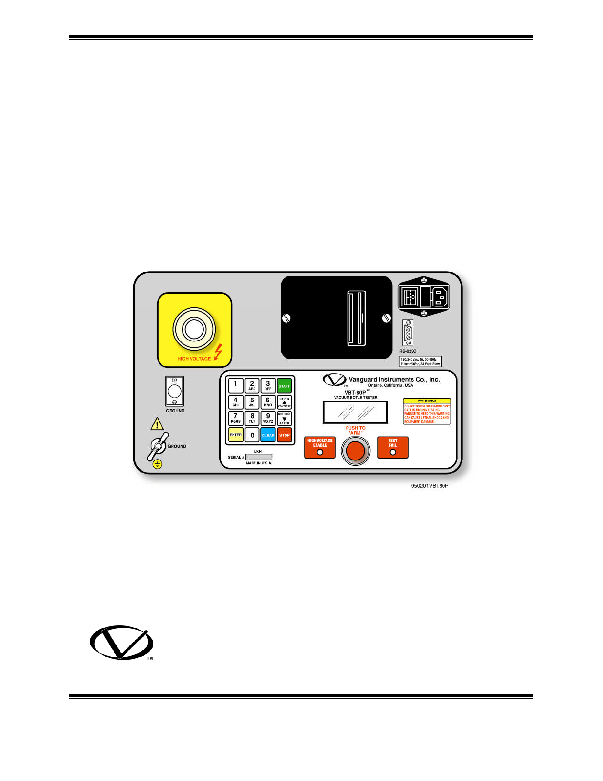
The VBT-80P is a lightweight DC vacuum bottle tester made by Vanguard Instruments
Company. The VBT-80P tests a vacuum bottle’s integrity by applying a DC voltage across the
bottle under test. A simple “PASS” or “FAIL” message indicates the condition of the bottle after
each test.
The VBT-80P is rugged and field-portable. It is easy to operate and requires little training for
first-time users. Operating the VBT-80P only requires connecting the test leads to the vacuum
bottle, selecting the desired test voltage, current threshold, and test time duration, then initiating
the test. A keypad with 16 alphanumeric keys allows the user to control and enter circuit breaker
test data. A built-in thermal printer produces test results on 2.5-inch-wide thermal paper. The
VBT-80P test records can be stored in its FLASH EEPROM memory. Up to 84 records (of 16
readings each) can be stored in the VBT-80P’s memory.
1.3 Functional Description
Using a voltage multiplier, the VBT-80P generates a programmable test voltage from 10,000Vdc
to 80,000Vdc in 1,000Vdc steps.
The test voltage can be applied for different time durations: 5 seconds, 10 seconds, 30 seconds, 1
minute, or 2 minutes. The current through the bottle is monitored by the VBT-80P’s circuitry
during a test. If this test current exceeds a preset threshold, the test is terminated and a test
“FAIL” message will be displayed on the LCD. The “TEST FAIL” indicator will also be
illuminated on the front panel.
The over current threshold can be programmed for 100 micro-amps, 200 micro-amps, or 300
micro-amps.
A test is considered successful if the selected test voltage was applied for the entire test time and
the test current did not exceed the preset threshold.
The VBT-80P’s LCD displays a “PASS” message along with the test voltage and test duration if
a test is successful. The “PASS” and “FAIL”” message can be printed on the built-in thermal
printer.
1.4 Furnished Test Accessories
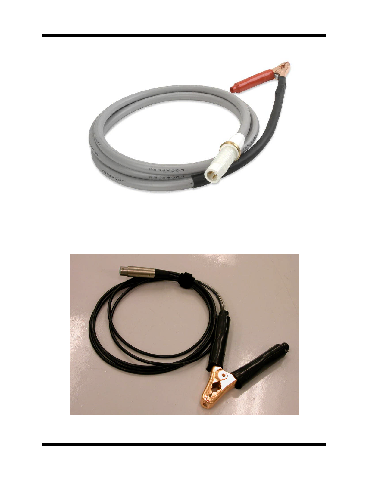
The VBT-80P is supplied with one 10-foot long high-voltage test cable, one 10 foot long
voltage-return lead with alligator clamps. A Ground cable, power cord, and a shipping case are
also included with each VBT-80P.
Note
The VBT-80P high voltage cable can be replaced in the field. Do not remove this HV cable from
the connector except for cable replacement.
4
Page 6
Operating Procedures VBT-80P
Figure 1 High voltage cable
Figure 2 High Voltage return cable
5
Page 7

Operating Procedures VBT-80P
2.0 VBT-80P SPECIFICATIONS
VBT-80P specifications and leading particulars are listed in Table 1.0
Table 1.0 VBT-80P Specifications
MODEL.......................VBT-80P
TYPE.............................Special-Purpose Test Equipment, portable 80 kV vacuum bottle tester
SIZE............................... 16.8” W by 3.5” H by 10.6” D (42.7 cm by 8.9 cm by 26.9 cm)
WEIGHT ....................... 10 pounds (4.53 Kg)
INPUT POWER ........... 2 amps, 90-240 Vac, 50/60 Hz
OUTPUT VOLTAGE... 10kV to 80kV dc in 1,000 volt steps
OUTPUT RIPPLE
VOLTAGE.................... 3% max
DISCHARGE TIME..... Maximum discharge time for internal high voltage is 0.3 seconds
DISPLAY...................... Back-lighted LCD, 4-lines by 16 characters
INDICATORS.............Test Failure Indicator: LED is turned on if test current exceeds
the preset current threshold (100A, 200A or 300A).
High Voltage Enable Indicator: LED is turned on when high voltage
is present on the high voltage cable.
PRINTER...................... 2.5” wide Thermal Printer
ENVIRONMENT.......... Operating: -10°C to 55°C (15F to +122F)
Storage: -30°C to 70°C (-22F to +158F)
FURNISHED ITEMS... One power cord, one ground cable, one 10-ft. high-voltage cable,
one 10-ft. high-voltage return cable.
OPTIONS ...................Transportation case included
WARRANTY................ One-Year Parts & Labor (Post-Warranty Service Contracts Available)
VBT-80P SPECIFICATIONS ARE SUBJECT TO UPGRADES AND MAY BE CHANGED WITHOUT PRIOR NOTICE.
6
Page 8
Operating Procedures VBT-80P
3.0 CONTROL AND DISPLAY
3.1 VBT-80P Front Panel
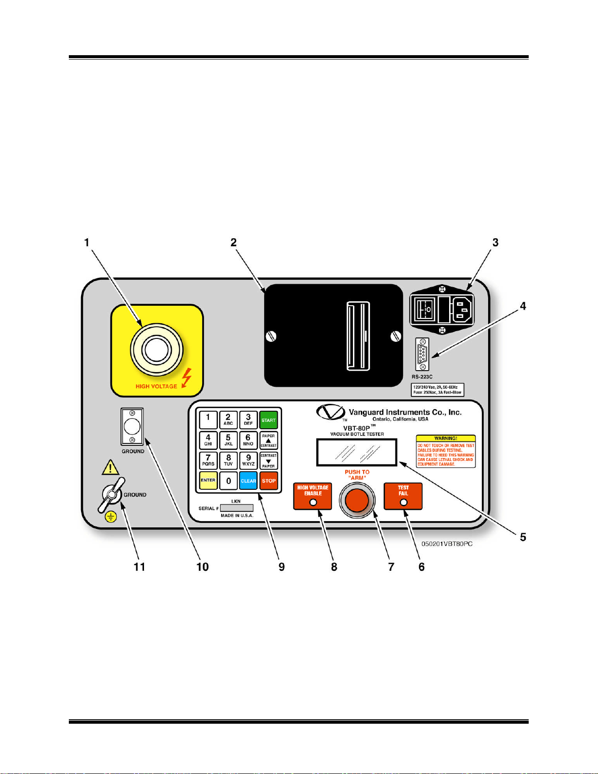
The VBT-80P controls and displays are shown in Figure 3. Pointing leader lines reference each
item with an index number. Each index number is cross-referenced to a functional description in
Table 2, which describes the function and purpose of each item on the control panel. Although
the purpose of these controls and the display may seem obvious and intuitive, users should
become familiar with them before attempting to use the VBT-80P. First-time users should also
review and become familiar with the Safety Summary on the front page.
Figure 3 VBT-80P Control-Panel Controls and Display
7
Page 9

Operating Procedures VBT-80P
Table 2.0 Functional Description of VBT-80P Controls and Display
Figure 1
Index #
1
2
3
4
5
Adjacent Panel Marking Functional Description
(Connector) High voltage cable connector
No marking
No marking Input power connector with built-in fuse
RS-232C
No marking
2.5” wide thermal printer
holder and power switch.
RS-232C interface port, 9-pin connector,
female DB type. The port is set to 19,200
baud, 1 start bit, 8 data bits, and no parity bit
PIN ................SIGNAL
2 Rx
3 Tx
5 Signal Gnd
This serial port is for factory calibration and
firmware updates
LCD, 4-line by 20-character, back-lighted:
displays menus of selections, operator entries,
and test measurement results.
6
7
8
9
10
11
TEST FAIL
PUSH TO
“ARM”
HIGH VOLTAGE
ENABLE
No marking 16-key keypad.
GROUND
GROUND
(Wing Nut)
Test Fail Indicator. This indicator is turned on
if the test current exceeds the preset current
threshold (100, 200, or 300 A).
Arm switch: Press and hold during a test
LED indicator, red: Lights when high voltage
is on the high voltage cable.
High-voltage-return cable connector.
VBT-80P ground stud. Connect ground stud
to substation ground using the provided cable.
8
Page 10

Operating Procedures VBT-80P
4.0 VBT-80P SPECIAL FEATURES
4.1 VBT-80P LCD Contrast Control
The VBT-80P LCD is back-lighted for viewing in low light conditions. To increase the LCD
display contrast, press and hold the “ Contrast” key for more than two seconds. To lighten the
LCD display contrast, press and hold the “ Contrast” key for more than two seconds.
4.2 Printer Paper Control
To advance paper, press and release the “ Paper” key.
To retract paper, press and release the “ Paper” key.
4.3 Printer Paper
The VBT-80P built-in thermal printer uses 2.5-inch wide thermal paper for printing test results.
In order to maintain the highest quality printing and to avoid paper jams we recommend using
the paper supplied by our factory. Paper can be ordered from the following two sources:
Vanguard Instruments Co, Inc.
1520 S. Hellman Ave.
Ontario, CA 91761
Tel: 909-923-9390
Fax: 909-923-9391
Part Number: TP-3 Paper
OR
BG Instrument Co.
13607 E. Trent Ave.
Spokane, WA 99216
Tel: 888-244-4004
Fax: 509-893-9803
Part Number: TP-3 paper
9
Page 11

Operating Procedures VBT-80P
5.0 VBT-80P CABLE CONNECTION
Always ground the VBT-80P before connecting any cables. Use the ground cable provided with
the cable set. A typical VBT-80P connection to a vacuum bottle is shown in figure 4.
Figure 4 Typical VBT-80P Connection
10
Page 12

Operating Procedures VBT-80P
1.RUN
TEST 07/06/06
1.
5 SEC. 2. 10 SEC
ENTER TEST VOLTAGE:
0
KV
ENTER TEST VOLTAGE:
61
KV
1. 300uA
3. 100uA
TEST PARAMETERS:
6.0 OPERATING PROCEDURES
(Refer to tables 3 through 8)
WARNING
Always connect the VBT-80P ground to the substation ground first.
6.1 Run Test Procedure
The following test procedure describes the steps required to run a test
Table 3 Run Test Procedure
STEP
3-1
3-2
3-3
3-4
ACTION DISPLAY
None. VBT-80P Main menu.
To begin the RUN TEST procedure, press
key # 1 (RUN TEST) on the MAIN
MENU. The “Test Duration” menu
appears.
Select a test time duration. Press key # 1
to select 5 seconds for this example.The
“Test Voltage” menu appears.
Note
Test voltage can be selected in the 1KV
steps.
Key in the test voltage using the the 0-9
keys.
2.SETUP 16:22:01
3. 30 SEC 4. 60 SEC
5. 2 MIN
(10 to 80)
(10 to 80)
3-5
3-6
Press the “Enter” key to confirm the entry.
The “Current Threshold” menu appears.
Select a current threshold. Press key # 1 to
select 300uA for this example.
The “Test parameters” display appears.
2. 200uA
61KV 5 SEC 300uA
“CLEAR” TO CHANGE OR
“ENTER” TO CONTINUE
11
Page 13

Operating Procedures VBT-80P
PRESS “ARM” SWITCH
TEST IN PROGRESS
TEST COMPLETED
PRINT TEST RESULTS?
SAVE THIS RECORD?
KEEP THIS READING?
RUN ANOTHER TEST?
TEST SAVED
TEST COMPLETED
Table 3 Run Test Procedure (Continued)
STEP
3-7
3-8
3-9
ACTION DISPLAY
Press the “ENTER” key to continue.
Press and hold the “ARM” Switch to run
the test.
A “TEST FAIL” message will appear if
the test current exceed the preset value
(300uA in this example) and the test will
terminate immediately. The “TEST FAIL”
LED will also be lit on the front panel.
A “TEST PASS” message will appear if
the test current did not exceed the current
threshold during the duration of the test.
TO START TEST
61KV 0.20uA
TIME 00:05
61KV 5 SEC 300uA
>>> FAIL <<<
61KV 5 SEC 300uA
>>> PASS <<<
3-10
3-11
3-12
3-13
3-14
Press the “ENTER” key to go to the print
menu
Press key #1 to print a test report. A
typical test report is shown in figure 5.
Press key #2 to skip printing.
Press key #1 to keep this reading.
Press key #2 to not store this reading in
working memory, go to step 3-14.
Press the “ENTER” key to advance to the
next menu.
Press key #1 to run another test, go to step
3-6.
Press key #2 to end the test.
1.YES
2.NO
1.YES
2.NO
1.YES
2.NO
1.YES
2.NO
12
Page 14

Operating Procedures VBT-80P
1.RUN
TEST 07/06/06
RECORD NUMBER 1
ARE YOU SURE?
Table 3 Run Test Procedure (Continued)
STEP
3-15
3-16
3-17
ACTION DISPLAY
Press key #1 to save the test record. The
test record is saved in the VBT-80P’s
Flash EEPROM. A test record number
will be assigned. Press the “ENTER” key
to return to the main menu.
Press key # 2 to skip saving the test
record. Go to step 3-16.
None. The user selected not to save the
test record; a reminder message is
displayed
Press key #2 to save the record. Go to step
3-15.
Press key #1 to abort saving the record.
The VBT-80P will return to the MAIN
MENU.
HAS BEEN SAVED!
DATA WILL BE LOST!
1.DO NOT SAVE RECORD
2.SAVE RECORD
2.SETUP 16:22:10
Note
1. A “FAIL” message will be displayed on the LCD and the “TEST FAIL” indicator will be
illuminated on the front panel.
2. The VBT-80P’s LCD displays a “PASS” message along with the test voltage and test duration
if a test is successful.
13
Page 15

Operating Procedures VBT-80P
Figure 5 Typical VBT-80P Test Report
14
Page 16

Operating Procedures VBT-80P
1.RECORD ID
COMPANY:
STATION:
CIRCUIT:
MANUFACTURER:
“ENTER” TO ACCEPT
MODEL:
1.RUN
TEST 07/06/06
6.2. Enter Test Record ID Procedure
This procedure allows the user to enter the equipment identification information to be used with
the test record. Each ID field can contain up to 20 characters. Always enter the test record ID
before starting a test.
Table 4 Enter Test Record ID Procedure
STEP ACTION DISPLAY
4-1
None. VBT-80P Main menu.
2.SETUP 16:22:01
4-2
4-3
4-4
4-5
On the MAIN MENU, press key # 2
(SETUP) to go to the Setup menu options
(shown at right).
Press key #1 (RECORD ID) to begin
entering identification information. The
“COMPANY:” input screen is displayed.
Enter the utility COMPANY name using
the alpha-numeric keypad. When finished,
press ENTER to store the data and go to
the “STATION:” input screen.
Enter the utility STATION name using the
alpha-numeric keypad. When finished,
press ENTER to store the data and go to
the “CIRCUIT:” input screen.
2.REVIEW RECORD
3.RESTORE RECORD
4.NEXT PAGE
UP/DOWN TO POSITION
“ENTER” TO ACCEPT
UP/DOWN TO POSITION
“ENTER” TO ACCEPT
UP/DOWN TO POSITION
“ENTER” TO ACCEPT
4-6
4-7
Enter the utility CIRCUIT name using the
alpha-numeric keypad. When finished,
press ENTER to store the data and go to
the “MANUFACTURER:” input screen.
Enter the utility MANUFACTURER name
using the alpha-numeric keypad. When
finished, press ENTER to store the data
and go to the “MODEL:” input screen.
15
UP/DOWN TO POSITION
UP/DOWN TO POSITION
“ENTER” TO ACCEPT
Page 17

Operating Procedures VBT-80P
OPERATOR:
1.RUN
TEST 07/06/06
SERIAL NUMBER:
KVA RATING:
“ENTER” TO ACCEPT
Table 4 Enter Test Record ID Procedure (continued)
STEP ACTION DISPLAY
4-8
Enter the utility MODEL name using the
alpha-numeric keypad. When finished,
press ENTER to store the data and go to the
“SERIAL NUMBER:” input screen.
UP/DOWN TO POSITION
“ENTER” TO ACCEPT
4-9
4-10
4-11
This completes the ENTER ID procedure.
The VBT-80P will retain the test record ID in memory until it is changed by the operator.
Enter the utility SERIAL NUMBER using
the alpha-numeric keypad. When finished,
press ENTER to store the data and go to the
“COMMENTS:” input screen.
Enter test COMMENTS using the alphanumeric keypad. When finished, press
ENTER to store the data and go to the
“OPERATOR:” input screen.
Enter the test OPERATOR name, using the
alpha- numeric keypad When finished, press
ENTER to store the data and return to the
MAIN MENU display.
NOTE
UP/DOWN TO POSITION
UP/DOWN TO POSITION
2.SETUP 16:27:00
16
Page 18

Operating Procedures VBT-80P
1.ENTER ID
1.RESTORE RECORD
RESTORE RECORD
RESTORE RECORD
REVIEW RECORD?
2.PRINT TEST RECORD
PRINT REPORT
6.3 Restore Record Procedure
This procedure describes how to restore a test record stored in VBT-80P’s Flash EEPROM to
working memory. The user can then print the test record with the thermal printer.
NOTE
The VBT-80P can store up to 84 test records in the FLASH EEPROM.
Table 5 Restore Test Record Procedure
STEP ACTION DISPLAY
5-1
On the MAIN MENU, press key #2
(SETUP) to display the SETUP MENU
options (shown at right).
2.REVIEW RECORD
3 RESTORE RECORD
4.NEXT PAGE
5-2
5-3
5-4
5-5
5-6
Press key #3 to select “RESTORE
RECORD”
Press key #1 to restore a record.
Press key #1 to enter the record number.
Enter the record number using the number
keys. Then press the ENTER key to confirm.
Press the“ENTER” key to display the
“REVIEW RECORD?” menu options.
2.DIRECTORY
3.ERASE RECORD
1.ENTER RECORD NUMBR
2.SCROLL TO SELECT
NUMBER:
RECORD RESTORED!
1.SCROLL TEST RECORD
5-7
This completes the Restore Record Procedure. A typical test result is shown in figure 5.
Press key #1 to scroll through the test record.
Press key #2 to print the test record on the
thermal printer.
Press “STOP” to return to the MAIN MENU.
PLEASE WAIT ………..
17
Page 19

Operating Procedures VBT-80P
1.ENTER ID
REVIEW RECORD
RECORD ID INFO
2 TESTS
TEST NUMBER: 1
TEST NUMBER: 2
1.RUN
TEST 07/06/06
6.4 Review Record Procedure
This procedure allows the user to view or print a test report residing in the VBT-80P’s working
memory
Table 6 Print Record Procedures
STEP ACTION DISPLAY
6-1
On the MAIN MENU, press key #2
(SETUP) to select the SETUP MENU
options (shown at right).
2.REVIEW RECORD
3.RESTORE RECORD
4.NEXT PAGE
6-2
6-3
6-4
6-5
Press key #2 to select the “REVIEW
RECORD” menu options.
1.SCROLL TEST RECORD
2.PRINT TEST RECORD
Press key #1 to Scroll through the test record
(see next menu).
Press key #2 to print the test record, return to
step 5-6 of the previous table.
Press “” key to view the next field.
07/06/06 16:20:01
Press “” key to view the next field.
10KV 5 Sec 100uA
0.00uA AT 10.0KV
TEST PASSED!
6-6
6-7
This completes Review Record Procedure.
Press “” key to view the next field.
10KV 5 Sec 100uA
0.00uA AT 10.0KV
TEST PASSED!
Press the “STOP” key to return to the MAIN
MENU display.
2.SETUP 16:27:00
18
Page 20

Operating Procedures VBT-80P
1.PRINT DIRECTORY
1.ENTER ID
1.RESTORE RECORD
PRINT DIRECTORY
RECORDS IN DIRECTORY
6.5 Print/View Test Record Directory Procedure
This procedure describes the steps to print or view the test record directory.
Table 7 Print Test Record Directory
STEP ACTION DISPLAY
7-1
On the MAIN MENU, press key #2
(SETUP) to select the SETUP MENU
options (shown at right).
2.REVIEW RECORD
3.RESTORE RECORD
4.NEXT PAGE
7-2
7-3
7-4
7-5
Press key#3 (RESTORE RECORD)
Press key #2 (DIRECTORY)
Press key #1 to select “Print Directory” (see
next menu).
Press key #2 to scroll through directory (see
7-6).
Press key #1 (FULL DIRECTORY) to
generate a list of all the records stored in
memory
Press key # 2 (SHORT DIRECTORY) to
generate a list of the last 10 records stored
in memory.
When the printout is completed, the display
returns to the MAIN MENU.
2.DIRECTORY
3.ERASE RECORD
2.SCROLL DIRECTORY
1.FULL DIRECTORY
2.SHORT DIRECTORY
PRINTING DIRECTORY
7-6
Continue from 7-4 after presssing key #2
(SCROLL DIRECTORY).
“UP” TO SCROLL FWD
“DWN” TO SCROLL RVS
19
Page 21

Operating Procedures VBT-80P
1.RUN
TEST 07/06/06
# 1 07/06/06 16:20:00
# 2 07/06/06 16:25:00
Table 7 Print Test Record Directory (Continued)
STEP ACTION DISPLAY
7-7
Press the “UP” key to view the first record’s
information.
1 TEST
7-8
7-9
This ends the Print/View Test Record Directory procedure.
Press the “UP” key to view next record’s
information.
Press key the “STOP” key to return to the
main menu.
2 TEST
2.SETUP 16:27:00
Figure 6 Typical VBT-80P Directory Print Out
20
Page 22

Operating Procedures VBT-80P
ERASE RECORD
ERASE RECORD
RECORD NUMBER: XX
ERASE ALL RECORDS!
ERASING RECORDS
PLEASE WAIT
RECORDS ERASED!
1.ENTER ID
4.NEXT PAGE
1.RESTORE RECORD
3.ERASE RECORD
6.6 Erase Test Record Procedure
This procedure describes the steps to delete one or all of the test records stored in the VBT-80P’s
Flash EEPROM.
Table 8 Erase Test Record Procedure
STEP ACTION DISPLAY
8-1
On the MAIN MENU, press key #2
(SETUP) to select the SETUP MENU
options (shown at right).
2.PRINT RECORD
3.RESTORE RECORD
8-2
8-3
8-4
8-5
8-6
Press key #3 (RESTORE RECORD)
Press key #3 (ERASE RECORD) to
display the ERASE RECORD menu
options (shown at right).
On the ERASE RECORD menu display,
press key #1 to erase a single record.
Go to step 8-6 to erase all the test records
stored in Flash EEPROM.
Enter the record number of the record to be
deleted then press the “ENTER” key to
confirm. Press the “ENTER” key again to
return to the Main menu.
NOTE
Press the the “STOP” key to abort.
Press key #2 to erase all records.
NOTE
Press the STOP key to abort.
2.DIRECTORY
1.ERASE SINGLE RECORD
2.ERASE ALL RECORDS
NUMBER: XX
ERASED!
Are you SURE?
“ENTER” TO CONTINUE
8-7
8-8
This ends the Erase Test Record procedure.
Press the “ENTER” key to confirm.
Press the “ENTER” key to return to the
Main menu.
21
Page 23

Operating Procedures VBT-80P
ENTER
ENTER
1.RUN
TEST 07/06/06
1.ENTER ID
4.NEXT PAGE
1.COMPUTER CONTROL
6.7 Set VBT-80P Real Time Clock
This procedure describes the steps to set the VBT-80P real time clock.
Table 9 Set Time Procedure
STEP ACTION DISPLAY
9-1
On the MAIN MENU, press key #2
(SETUP) to select the SETUP MENU
options (shown at right).
2.PRINT RECORD
3.RESTORE RECORD
8-2
8-3
8-4
8-5
This ends the Set Time procedure.
Press key #4 (NEXT PAGE)
Press key #2 (SET TIME)
Use the number keys to enter the current
date and time.
The VBT-80P will return to the main menu
after the date and time are entered.
2.SET TIME
MM-DD-YY HH:MM:SS
MM-DD-YY HH:MM:SS
2.SETUP 16:27:00
22
Page 24

Operating Procedures VBT-80P
1520 S. Hellman Ave., Ontario, CA 91761, USA
Phone 909-923-9390 Fax 909-923-9391
www.vanguard-instruments.com
23
VBT-60/80 August 2006
 Loading...