

Page 1
OPERATING INSTRUCTIONS
for the
VBT-60/80
Vacuum Bottle Tester
Vanguard Instruments Company
1710 Grevillea Court
Ontario, California 91761
TEL: (909) 923-9390 August 2005
FAX: (909) 923-9391 Rev. 1
Page 2

VBT-60/80 Operating Procedures
SAFETY SUMMARY
NOTICE
This manual applies to Models VBT-60, and VBT-80. The operating procedures are virtually
the same for all models; any differences are clearly described in the step-by-step procedures.
Follow Exact Operating Procedures
Any deviation from the procedures described in this operator’s manual may create one or more
safety hazards, damage the VBT, or cause errors in the test results; Vanguard Instruments Co.,
Inc. assumes no liability for unsafe or improper use of the VBT.
The following safety precautions must be observed during all phases of test set up, test hookups,
testing, and test-lead disconnects.
SAFETY WARNINGS AND CAUTIONS
This device shall be used only by trained operators.
All circuit breakers under test shall be off line and fully isolated.
Do Not Modify Test Equipment
Because of the risk of introducing unknown hazards, do not install substitute parts or perform
any unauthorized modification to any Model VBT Test unit. To ensure that all designed safety
features are maintained, it is recommended that repairs be performed only by Vanguard
Instruments Co. factory personnel or by an authorized repair service. Unauthorized
modifications can cause serious safety hazards and will nullify the manufacturer's warranty.
2
Page 3

VBT-60/80 Operating Procedures
Table of Contents
1.0 INTRODUCTION ...............................................................................................................6
1.1 Applicability .....................................................................................................................6
1.2 General Description...........................................................................................................6
1.3 Functional Description ......................................................................................................6
1.4. Furnished Test Accessories ..............................................................................................6
2.0 VBT SPECIFICATIONS .....................................................................................................8
2.1 VBT-60 Specifications......................................................................................................8
2.2 VBT-80 Specifications......................................................................................................9
3.0 CONTROL AND DISPLAY..............................................................................................10
3.1 VBT-60 Front Panel........................................................................................................10
3.2. VBT-80 Front Panel.......................................................................................................12
4.0 VBT-60/80 IMPORTANT FEATURES.............................................................................14
4.1 Operating Voltages..........................................................................................................14
4.2 VBT-60/80 Serial Interface .............................................................................................14
5.0 CABLE CONNECTION....................................................................................................15
6.0 OPERATING PROCEDURES...........................................................................................16
6.1 0 Preparations..................................................................................................................16
6.1.1 Setup and Run Test Procedure......................................................................................16
6.1.2. Repeat Test Procedure.................................................................................................17
6.1.3. Change VBT Test Duration, Test Voltage and Test Current Threshold........................18
6.1.4. Set VBT Clock............................................................................................................19
6.1.5. Set VBT LCD Contrast ...............................................................................................19
6.1.5 VBT Test PASS Display...............................................................................................20
6.1.6 VBT Test FAIL Display...............................................................................................20
3
Page 4

VBT-60/80 Operating Procedures
List of Figures
Figure 1. High voltage cable ......................................................................................................7
Figure 2. High Voltage return cable ...........................................................................................7
Figure 3. VBT-60 Control-Panel Controls and Display.............................................................10
Figure 4. VBT-80 Control-Panel Controls and Display.............................................................12
Figure 5. VBT-60 Connection Diagram 1.................................................................................15
Figure 6. VBT-80 Connection Diagram 2.................................................................................15
Figure 7. “PASS” Message ......................................................................................................20
Figure 8. “FAIL” Message.......................................................................................................20
4
Page 5

VBT-60/80 Operating Procedures
List of Tables
Table 1.0. VBT-60 Specifications ..............................................................................................8
Table 2.0. VBT-80 Specifications ..............................................................................................9
Table 3.0. Functional Description of VBT-60 Controls and Display.........................................11
Table 4.0 Functional Description of VBT-80 Controls and Display..........................................13
Table 5. Setup and Run Test Procedure....................................................................................16
Table 6. Repeat Test Procedure................................................................................................17
Table 7. Set VBT Test Duration, Voltage, Current...................................................................18
Table 8. Set VBT Clock...........................................................................................................19
Table 9. Set VBT LCD Contrast ..............................................................................................19
5
Page 6

VBT-60/80 Operating Procedures
1.0 INTRODUCTION
1.1 Applicability
This manual applies to the Model VBT-60™ and Model VBT-80™ (hereafter, VBT), made by
Vanguard Instruments Company, Inc.
1.2 General Description
The VBT-60 and VBT-80 are light-weight DC vacuum bottle testers made by Vanguard
Instruments Company. The VBT tests the vacuum bottle integrity by applying a DC voltage
across the bottle under test. A simple “PASS” or “FAIL” message indicates the condition of the
bottle after each test. The VBT is field-portable, rugged, and is easily operated by first-time users
having a minimum of training. It features a “Turn-then-Press” control knob for entering test
parameters and control functions.
Turning the knob scrolls through a menu of possible options (which display in sequence) and
pressing the knob activates the selected function
A 2-line by 16-character LCD alpha/numeric readout is used for displaying control-option
menus, and test results. The operation requires little more than connecting test leads to the
vacuum bottle, selecting the desired test voltage and test duration.
1.3 Functional Description
Using a voltage multiplier, the VBT-60 generates a programmable test voltage from 10,000 V dc
to 60,000 V dc (or 10,000 V dc to 80,000 for VBT-80) with 5,000 V dc steps.
The test voltage can be applied at different time durations: 5 seconds, 10 seconds, 30 seconds, 1
minute, or 2 minutes. Test current is monitored by the VBT electronics during test. If this test
current exceeds a preset threshold, the test is terminated and a test “FAIL” message is displayed.
The over-current threshold is programmable at 100 micro-amps, or 200 micro-amps, or 300
micro-amps.
A “FAIL” message will be displayed on the LCD and “TEST FAIL” indicator will be
illuminated on the front panel.
A test is considered successful if the selected test voltage was applied for the full test duration
and the test current did not exceed the preset threshold.
The VBT’s LCD displays “PASS” message along with the test voltage and test duration if a test
is successful.
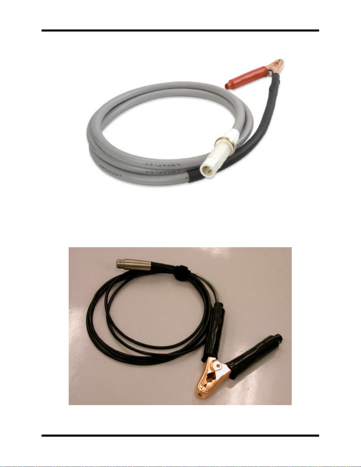
1.4. Furnished Test Accessories
The VBT is supplied with one 10-foot long high-voltage test cable, one 10-foot long voltagereturn lead with alligator clamps. A Ground cable, power cord and a shipping case are also
included with each VBT.
6
Page 7
VBT-60/80 Operating Procedures
Figure 1. High voltage cable
Figure 2. High Voltage return cable
7
Page 8

VBT-60/80 Operating Procedures
2.0 VBT SPECIFICATIONS
2.1 VBT-60 Specifications
VBT-60 specifications and leading particulars are listed in Table 1.0.
Table 1.0. VBT-60 Specifications
MODEL.......................VBT-60
TYPE............................Special-Purpose Test Equipment, portable 60 kV vacuum bottle tester
SIZE (inches)..............16.8 W by 3.5 H by 10.6 D (42.7 cm by 8.9 cm by 26.9 cm)
WEIGHT.......................10 pounds (4.53 Kg)
INPUT POWER...........2 amps, 90-240 Vac, 50/60 Hz
OUTPUT VOLTAGE...10kV to 60kV dc in 5,000 volt steps
OUTPUT RIPPLE
VOLTAGE....................3% max
DISCHARGE TIME.....Max imum discharge time for internal high voltage is 0.3 seconds
DISPLAY......................Backlit LCD, 2-lines by 16 characters
INDICATORS .............Test failure indicator: LED is turned on if test current exceeds
the preset current threshold (100?A, 200?A or 300?A).
High Voltage Enable Indicator: LED is turned on when high voltage
is present at high voltage cable.
CONTROL...................Single knob selector (turn-and-press selection)
COMPUTER
INTERFACE ................RS-232C port, 19,200 Baud (Factory Calibration and Diagnostic)
ENVIRONMENT..........Operating: -10°C to 55°C (15?F to +122?F)
Storage: -30°C to 70°C (-22?F to +158?F)
FURNISHED ITEMS...One power cord, one ground cable, one 10-ft. high-voltage cable,
One 10-ft. high-voltage return cable.
OPTIONS ...................Transportation case included
WARRANTY ................ One-Year Parts & Labor (Post-Warranty Service Contracts Available)
VBT-60 SPECIFICATIONS ARE SUBJECT TO UPGRADES AND MAY BE CHANGED WITHOUT PRIOR NOTICE.
8
Page 9

VBT-60/80 Operating Procedures
2.2 VBT-80 Specifications
VBT-80 specifications and leading particulars are listed in Table 2.0
Table 2.0. VBT-80 Specifications
MODEL.......................VBT-80
TYPE............................Special-Purpose Test Equipment, portable 80 kV vacuum bottle tester
SIZE (inches)..............16.8 W by 3.5 H by 10.6 D (42.7 cm by 8.9 cm by 26.9 cm)
WEIGHT.......................10 pounds (4.53 Kg)
INPUT POWER...........2 amps, 90-240 V ac, 50/60 Hz
OUTPUT VOLTAGE...10 kV to 80 kV dc in 5,000-volt steps
OUTPUT RIPPLE
VOLTAGE....................3% max
DISCHARGE TIME.....Maximum discharge time for internal high voltage is 0.3 seconds
DISPLAY......................Backlit LCD, 2-lines by 16 characters
INDICATORS .............Test failure indicator: LED is turned on if test current exceeds
the preset current threshold (100?A, 200?A or 300?A).
High Voltage Enable Indicator: LED is turned on when high voltage
is present at high voltage cable.
CONTROL...................Single knob selector (turn-and-press selection)
COMPUTER
INTERFACE ................RS-232C port, 19,200 Baud (Factory Calibration and Diagnostic)
ENVIRONMENT..........Operating: -10°C to 55°C (15?F to +122?F)
Storage: -30°C to 70°C (-22?F to +158?F)
FURNISHED ITEMS...One power cord, one ground cable, one 10-ft. high-voltage cable,
One 10-ft. high-voltage return cable.
OPTIONS ...................Transportation case included
WARRANTY ................ One-Year Parts & Labor (Post-Warranty Service Contracts Available)
VBT-80 SPECIFICATIONS ARE SUBJECT TO UPGRADES AND MAY BE CHANGED WITHOUT PRIOR NOTICE.
9
Page 10

VBT-60/80 Operating Procedures
3.0 CONTROL AND DISPLAY
3.1 VBT-60 Front Panel
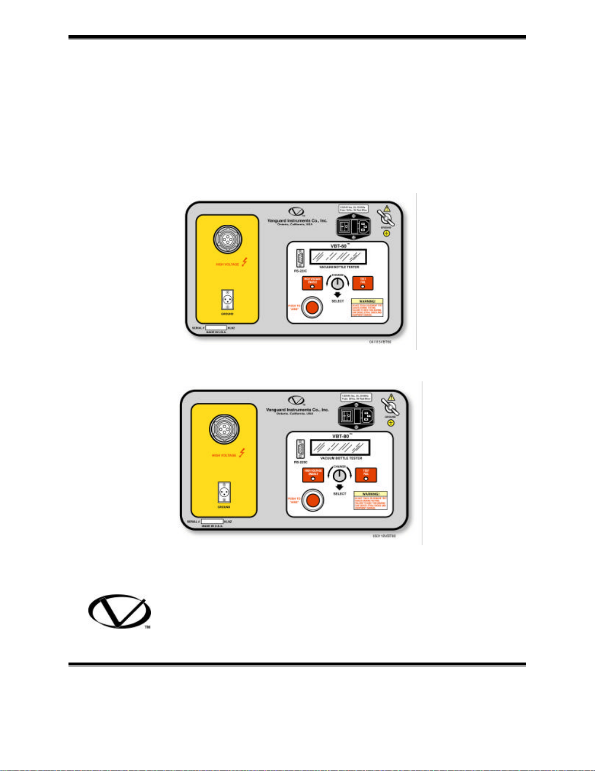
The VBT-60 controls and displays are shown in Figure 3. Pointing leader lines reference each
item with an index number. Each index number is cross-referenced to a functional description in
Table 3, which describes the function and purpose of each item on the control panel. Although
the purpose of these controls and the display may seem obvious and intuitive, users should
become familiar with them before attempting to use the VBT-60. First-time users should also
review and become familiar with the Safety Summary on the front page.
Figure 3. VBT-60 Control-Panel Controls and Display
10
Page 11

VBT-60/80 Operating Procedures
Table 3.0. Functional Description of VBT-60 Controls and Display
Figure 1
Index #
1 (Connector) High-voltage-cable connector
2
3 90-230 Vac, 8A, 50- 60 Hz Input power connector with built-in fuse
4 GROUND
5
Adjacent Panel Marking Functional Description
RS-232C
(Wing Nut)
No marking
RS-232C interface port; 9-pin connector;
female DB type. The data are set to 19,200
baud, 1 start bit, 8 data bits, and no parity bit;
PIN ...............SIGNAL
2 Rx
3 Tx
5 Signal Gnd
This serial port is for factory calibration and
firmware updates
holder and power switch.
VBT ground stud. Connect ground stud to
substation ground using the provided cable.
LCD; 2-line by 16-character; back-lighted;
displays menus of selections, operator entries,
and test-measurement results.
6
TEST FAIL
7
CHANGE
SELECT
8 HIGH VOLTAGE
ENABLE
9 PUSH TO
“ARM”
10 GROUND High-voltage-return cable connector.
Test Fail Indicator. This indicator is turned on
if the test current exceeds the preset current
threshold (100, 200, or 300 ?A).
VBT control knob. Turn knob to desired new
feature. Press knob to select that new feature
LED indicator, red; Lights when high-testvoltage is present at the test leads.
Arm switch; Press and hold during test
11
Page 12

VBT-60/80 Operating Procedures
3.2. VBT-80 Front Panel
The VBT-80 controls and displays are shown in Figure 4. Pointing leader lines reference each
item with an index number. Each index number is cross-referenced to a functional description in
Table 4, which describes the function and purpose of each item on the control panel. Although
the purpose of these controls and the display may seem obvious and intuitive, users should
become familiar with them before attempting to use the VBT-80. First-time users should also
review and become familiar with the Safety Summary on the front page.
Figure 4. VBT-80 Control-Panel Controls and Display
12
Page 13

VBT-60/80 Operating Procedures
Table 4.0 Functional Description of VBT-80 Controls and Display
Figure 1
Index #
1 (Connector) High-voltage-cable connector
2
3 90-230 Vac, 8A, 50- 60 Hz Input power connector with built-in fuse
4 GROUND
5
Adjacent Panel Marking Functional Description
RS-232C
(Wing Nut)
No marking
RS-232C interface port; 9-pin connector;
female DB type. The data are set to 19,200
baud, 1 start bit, 8 data bits, and no parity bit;
PIN ...............SIGNAL
2 Rx
3 Tx
5 Signal Gnd
This serial port is for factory calibration and
firmware updates
holder and power switch circuit breaker.
VBT ground stud. Connect ground stud to
substation ground using the provided cable.
LCD; 2-line by 16-character; back-lighted;
displays menus of selections, operator entries,
and test-measurement results.
6
TEST FAIL
7
CHANGE
SELECT
8 HIGH VOLTAGE
ENABLE
9 PUSH TO
“ARM”
10 GROUND High-voltage-return cable connector.
Test Fail Indicator. This indicator lights if the
test current exceeds the preset current
threshold (100, 200, or 300 ?A).
VBT control knob. Turn knob to desired new
feature. Press knob to select that feature.
LED indicator, red; Lights when high-testvoltage is present at the test leads.
Arm switch; Press and hold during test
13
Page 14

VBT-60/80 Operating Procedures
4.0 VBT-60/80 IMPORTANT FEATURES
4.1 Operating Voltages
The VBT-60/80 operates with voltages between 90-240Vac, 50/60Hz.
4.2 VBT-60/80 Serial Interface
A built-in, RS-232C port is used to calibrate the VBT at the factory and to perform field firmware
upgrade.
14
Page 15

VBT-60/80 Operating Procedures
5.0 CABLE CONNECTION
The VBT is supplied with one 10-foot “High Voltage” cable and one 10-foot voltage-return
cable. Both cables are terminated with alligator clamps to connect to the vacuum bottle being
tested. A typical cable connection for the VBT to a Vacuum bottle under test is shown in Figure
5 and Figure 6. To protect the VBT against static discharge in the substation, always connect the
unit’s ground stud to the substation ground.
Note:
1. The circuit breaker must be off line and completely isolated. The vacuum bottle under test
should be in the open position.
Figure 5. VBT-60 Connection Diagram 1
Figure 6. VBT-80 Connection Diagram 2
15
Page 16

VBT-60/80 Operating Procedures
6.0 OPERATING PROCEDURES
Review Figures 5 and 6 before proceeding with the step-by-step procedures that follow.
6.1 0 Preparations
a. Make sure the circuit breaker under test is off line and isolated. The vacuum bottle under test
should be isolated and in opened position.
b. Make sure the VBT power switch is in the off position.
c. Ground the VBT to Substation ground.
d. Plug the VBT power cable into a power outlet.
e. Connect the VBT high-voltage cable end (Red clip) to one side of vacuum bottle (see Figures
5 & 6).
f. Connect the VBT high-voltage-return cable (black clip) to the other side of the vacuum bottle.
g. Turn on the VBT power, by pressing the rocker switch to the ON position.
6.1.1 Setup and Run Test Procedure
The following steps are required to run a test with the VBT-60/80 (when power is first applied to
the VBT-60/80).
Table 5. Setup and Run Test Procedure
STEP DESCRIPTION DISPLAY ACTION
1 Initiate a test MAIN: <RUN TEST>
18:02:00
2 Select Test Duration TIME: <5 Sec>
18:02:05
3 Confirm Test
Duration
4 Select Test Voltage VLTG: <10 KV>
5 Confirm Test Voltage VLTG: <60 KV>
6 Select Flash-Over
Threshold
7 Confirm Threshold Thres: <300 uA>
8 Confirm Test setting “PRESS” IF OKAY
9 Start Test Now PRESS RED SWITCH
10 Test in progress 60.0KV 0.20uA
11 Observe PASS/FAIL 60KV 10Sec 300uA
12 Return to Main Menu 60KV 10Sec 300uA
TIME: <10 Sec>
18:02:07
18:02:10
18:02:15
Thres: <100 uA>
18:02:17
18:02:20
60KV 10Sec 300uA
TO START TEST
Time: 00.04
>>PASS<<
>>PASS<<
Press knob
Turn knob to
desired time
Press knob
Turn knob to desired
voltage
Press knob
Turn knob to desired
threshold
Press knob
Press knob
Press and hold RED
Switch
Press and hold RED
Switch
Release “RED” switch
Press knob
16
Page 17

VBT-60/80 Operating Procedures
6.1.2. Repeat Test Procedure
The following steps shall be used to repeat a test.
Table 6. Repeat Test Procedure
STEP DESCRIPTION DISPLAY ACTION
1 Initiate a test MAIN: <RUN TEST>
20:02:00
2 Confirm current
setting
3 Start Test Now PRESS RED SWITCH
4 Test in progress 60.0KV 0.20uA
5 Observe PASS/FAIL 60KV 10Sec 300uA
6 Return to Main Menu 60KV 10Sec 300uA
“PRESS” IF OKAY
60KV 10Sec 300uA
TO START TEST
Time: 00.04
>>PASS<<
>>PASS<<
Press knob
Press knob
Press and hold RED
Switch
Press and hold RED
Switch
Release RED Switch
Press knob
Note:
1. To change the Test Voltage, Test duration, or Over current setting, use SET UP menu.
2. A “FAIL” message will be displayed on the LCD and “TEST FAIL” indicator will be
illuminated on the front panel.
3. The VBT’s LCD displays “PASS” message along with the test voltage and test duration if a
test is successful.
17
Page 18

VBT-60/80 Operating Procedures
6.1.3. Change VBT Test Duration, Test Voltage and Test Current Threshold
The test duration can be set at 5 seconds, 10 seconds, 30 seconds, 1 minute, or 2 minutes.
The test voltage for the VBT-60 can be set from 10 kv DC to 60 kv DC with 5 kv DC steps.
The test voltages for the VBT-80 can be set from 10 kv DC to 80 kv DC with 5 kv DC steps.
Test current threshold can be set at 100 ?A or 200?A or 300?A.
Use the following steps to select test duration, test voltage and test current threshold.
Table 7. Set VBT Test Duration, Voltage, Current
STEP DESCRIPTION DISPLAY ACTION
1 Select SETUP mode MAIN: <RUN TEST>
21:02:00
2 Go to SETUP mode MAIN: <SETUP>
21:02:05
3 Change time duration TIME: <5 Sec>
21:02:06
4 Select 10 second test
time
5 Change voltage
setting
6 Select 20 KV test
voltage
7 Change Current
threshold setting
8 Return to Main Menu MAIN: <RUN TEST>
TIME: <10 Sec>
21:02:07
VLTG: <10 KV>
21:02:08
VLTG: <20 KV>
21:02:09
Thres: <100 ?A>
21:02:10
21:02:05
Turn knob
Press knob
Turn knob to change time.
Press knob to select
Turn knob to change
voltage
Press to select voltage
Turn knob then press to
select
None
18
Page 19

VBT-60/80 Operating Procedures
6.1.4. Set VBT Clock
Use the following steps to set the VBT real time clock.
Table 8. Set VBT Clock
STEP DESCRIPTION DISPLAY ACTION
1 Select Utility Mode MAIN: <RUN TEST>
21:02:00
2 Confirm Utility Mode
Setting
3 Change Time UTIL: <SET TIME>
4 Change Month MM-DD-YY HH:MM
5 Change Day setting MM-DD-YY HH:MM
6 Change Year setting MM-DD-YY HH:MM
7 Change Hour setting MM-DD-YY HH:MM
8 Change Minute
setting
9 Return to Main Menu MAIN: <RUN TEST>
MAIN: <UTIL>
21:02:05
21:02:06
0
05-
03-02-0
03-02-05 0
MM-DD-YY HH:MM
03-02-05 21:0
21:05:00
Turn knob
Press knob
Press to select
Turn knob then press to
select
Turn knob then press to
select
Turn knob then press to
select
Turn knob then press to
select
Turn knob then press to
select
None
6.1.5. Set VBT LCD Contrast
Use the following steps to set the VBT LCD contrast. The contrast setting will be saved in
memory.
Table 9. Set VBT LCD Contrast
STEP DESCRIPTION DISPLAY ACTION
1 Select Contrast Mode MAIN: <RUN TEST>
21:02:00
2 Confirm Contrast
Mode Setting
3 Adjust LCD contrast CONTRAST ADJUST
4 Return to Main Menu MAIN: <RUN TEST>
MAIN: <CONTRAST>
21:02:05
“PRESS” To EXIT
21:05:00
Turn knob
Press knob
Turn knob then press to
select
None
19
Page 20

VBT-60/80 Operating Procedures
6.1.5 VBT Test PASS Display
After a successful test, the VBT will display the following message on the LCD. Turn or press
the control knob will return the display to the main menu.
Test Duration Test Current Threshold
10KV 5 Sec 100?A
Test voltage
>>> PASS <<<
Test Pass
Figure 7. “PASS” Message
6.1.6 VBT Test FAIL Display
After a failed test, the VBT will display the following message on the LCD and the “TEST
FAIL” indicator is also illuminated.
10KV 5 Sec 100?A
>>> FAIL <<<
Test Fail
Figure 8. “FAIL” Message
20
Page 21

VBT-60/80 Operating Procedures
1710 Grevillea Court. Ontario, CA 91761, USA
Phone 909-923-9390 Fax 909-923-9391
Web site: http//www.vanguard-instruments.com
VBT-60/80 August 2005
21
 Loading...