

Page 1
OPERATING PROCEDURES
for the
UPS-S2
Universal Power Supply Series 2
Vanguard Instruments Co., Inc.
TEL: 909-923-9390 November 2013
FAX: 909-923-9391 REV. 2
1520 S. Hellman Ave.
Ontario, California 91761
Page 2

Operating Procedures UPS-S2
SAFETY SUMMARY
Follow Exact Operating Procedures
Any deviation from the procedures described in this operator’s manual may create one or more
safety hazards and damage the UPS-S2. Vanguard Instruments Co., Inc. assumes no liability for
unsafe or improper use of the UPS-S2.
The following safety precautions must be observed during all phases of test set-up, test hookups,
testing, and test-lead disconnection.
SAFETY WARNINGS AND CAUTIONS
This device shall be used only by trained operators.
Always ground the UPS-S2 to a substation ground.
Precaution with High Test Voltage
The UPS-S2 can produce a voltage greater than 300Vac which can cause severe injury, death,
and/or equipment damage.
Do Not Modify Test Equipment
Because of the risk of introducing unknown hazards, do not install substitute parts or perform
any unauthorized modification to any Model UPS-S2 unit. To ensure that all designed safety
features are maintained, it is recommended that repairs be performed only by Vanguard
Instruments Co. factory personnel or by an authorized repair service. Unauthorized
modifications can cause serious safety hazards and will nullify the manufacturer's warranty.
Page 3

Page 4

Operating Procedures UPS-S2
TABLE OF CONTENTS
Safety Summary
1.0 INTRODUCTION ................................................................................................................... 2
1.1.General Description .............................................................................................................. 2
1.4 Furnished Test Accessories ................................................................................................... 2
2.0 UPS-S2 Specifications .......................................................................................................... 3
3.0 CONTROLS AND INDICATORS .......................................................................................... 4
3.1 UPS-S2 Controls & Indicators .............................................................................................. 4
4.0 PRETEST SETUP ................................................................................................................... 6
4.1 Operating Voltages ............................................................................................................... 6
4.2 UPS-S2 output voltage .......................................................................................................... 6
5.0 UPS-S2 CABLE CONNECTIONS ......................................................................................... 7
6.0 UPS-S2 Operational procedures .............................................................................................. 7
6.1 UPS-S2 DC Supply Setting .................................................................................................. 7
6.2 UPS-S2 AC Supply Setting .................................................................................................. 8
Appendix A EZCT™ Troubleshooting Guide
LIST OF TABLES
Table 1 UPS-S2 Specifications ................................................................................................... 3
Table 3 UPS-S2 Output Voltage with 120Vac input ..................................................................... 6
Table 4 UPS-S2 Output Voltage with 240Vac input ..................................................................... 6
LIST OF FIGURES
Figure 1 UPS-S2™ Control Panel (Controls and Indicators) ........................................................ 4
Figure 3 Variac Terminals ............................................................................................................. 6
Figure 3 Typical UPS-S2 Cable Connection ................................................................................. 7
1
Page 5

Operating Procedures UPS-S2
1.0 INTRODUCTION
1.1.General Description
The Vanguard Universal Power Supply Series 2 (UPS-S2) is designed and produced to meet a
utility company’s substation need for an independent AC/DC power source. Both the AC and
DC voltage sources are capable of supplying 10 amperes continuously.
The variable output DC power supply (1-300Vdc) is ideal for use as a substitute primary power
source when station batteries are not available. It is ideal for operating Circuit Breakers,
powering substation relays, or for unregulated charging of substation batteries.
The AC power supply is a variable (1-240Vac) isolated power source that can be used to power
other equipment in the substation.
Main features of the Universal Power Supply are:
1. All output power sources are isolated from the primary power input by an isolation
transformer.
2. Voltage outputs are continuously variable (auto-transformer) with a Front Panel
control knob.
3. The Universal Power Supply’s primary power input is user selectable to be either
120Vac or 240Vac.
4. All voltage outputs are capable of supplying a continuous 10 ampere load
5. The power output routing path is clearly outlined on the Control Panel, which allows
users to intuitively make the appropriate control function selections for the desired
operating configuration.
The UPS-S2 is contained in a heavy duty, impact resistance plastic case. Each Universal Power
Supply is warranted by Vanguard Instruments Incorporated for one year and covers parts and
labor for failures resulting under normal use.
1.4 Furnished Test Accessories
The UPS-S2 is supplied with a power cord, one ground cable, two 10-foot test lead sets with
alligator clips.
2
Page 6

Operating Procedures UPS-S2
2.0 UPS-S2 SPECIFICATIONS
Table 1 UPS-S2 Specifications
MODEL ................................................... UPS-S2
TYPE ....................................................... Special-purpose test equipment, Universal AC/DC power supply
POWER ................................................... 85 to 132Vac or 200-240Vac (factory preset), 50/60 Hz
SIZE (inches) .......................................... 21”W by 17”H by 9”D (53cm x 43cm x 24cm)
WEIGHT .................................................. 52lbs
AC OUTPUT VOLTAGE ......................... 0 to 240Vac @ 10A max.
DC OUTPUT VOLTAGE ......................... 0 to 300Vdc @ 10A max
ENVIRONMENT ...................................... Operating: 0°C to 55°C; Storage: -40°C to 65°C
FURNISHED ........................................... One power cord, two 10-ft test lead sets, One ground cable,
WARRANTY ........................................... One-year warranty on parts and labor; post warranty service
contracts available
NOTE:
▪THE ABOVE SPECIFICATIONS ARE VALID AT NOMINAL OPERATING VOLTAGE AND AT A TEMPERATURE OF 25
▪UPS-S2
™
SPECIFICATIONS MAY BE UPGRADED AND CHANGED WITHOUT PRIOR NOTICE.
°
C (77°F)
3
Page 7

Operating Procedures UPS-S2
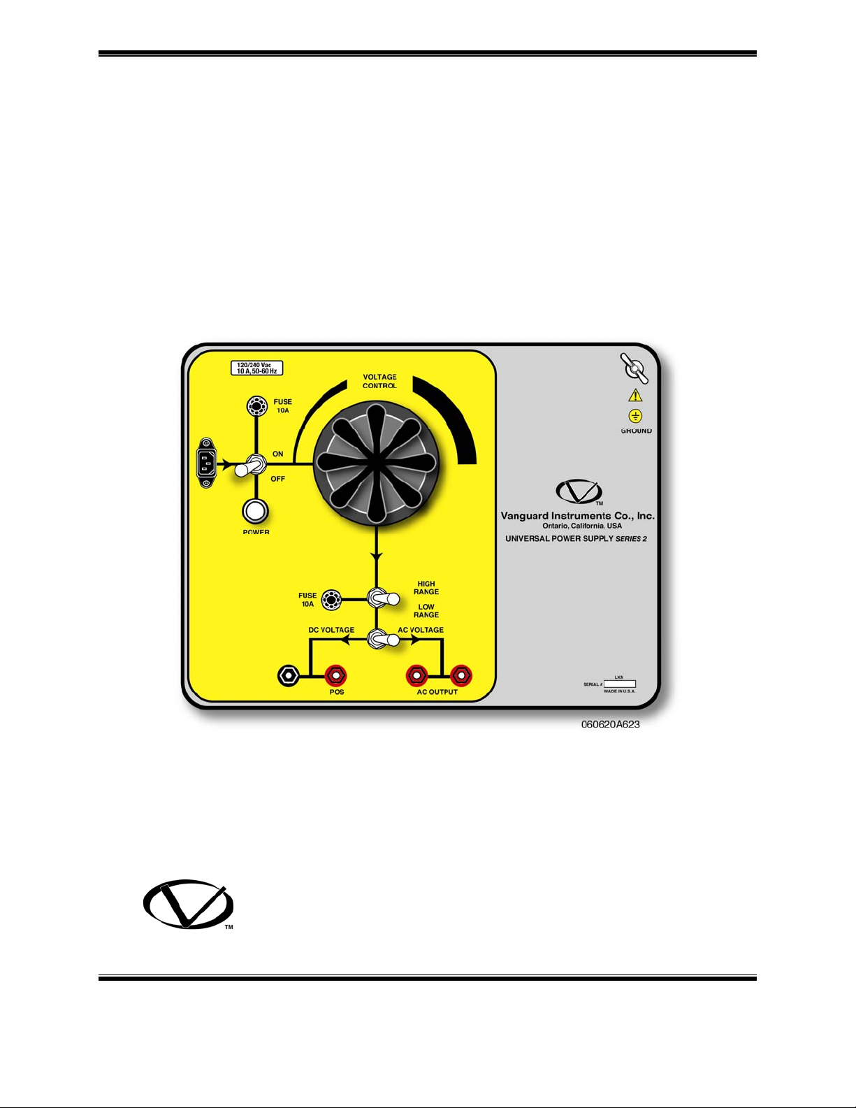
3.0 CONTROLS AND INDICATORS
3.1 UPS-S2 Controls & Indicators
The UPS-S2 controls and indicators are shown in a panel illustration (see Figure 1). Pointing
leader lines reference each item in the figure with an index number. Each index number is crossreferenced to a functional description in Table 2.0, which describes the purpose of each item on
the control panel. Although the purpose of these controls and the display may seem obvious,
users should become familiar with them before attempting to use the UPS-S2. Accidental misuse
of the controls will usually cause no serious equipment damage. First-time users should review
and become familiar with the Safety Summary located in the front section of this manual.
Figure 1 UPS-S2™ Control Panel (Controls and Indicators)
4
Page 8

Operating Procedures UPS-S2
Table 2 EZCT™ Controls and Indicators
Fig. 1
Index
1
2
3
4
5
6
7 & 8
9
10 & 11
12
13
PANEL MARKING
(No Marking)
(no marking)
FUSE 10A
VOLTAGE
CONTROL
HIGH RANGE
LOW RANGE
GROUND
AC OUTPUT
DC VOLTAGE
AC VOLTAGE
POS
FUSE 10A
POWER
FUNCTIONAL DESCRIPTION
Input power connector with third wire safety
ground.
Power Switch
Main input power protection fuse.
250 Vac/10 Ampere slow-blow.
Test voltage control knob
Output voltage range selection.
Ground Stud
AC output connectors (2).
AC or DC voltage selector switch
DC output connectors (2).
Output voltage protection fuse.
250 Vac/10 Ampere slow-blow
Power on indicator
5
Page 9

Operating Procedures UPS-S2
4.0 PRETEST SETUP
4.1 Operating Voltages
The UPS-S2™ operating voltages are pre-set for 90-130Vac, 50/60Hz or 210-240Vac, 50/60Hz.
at the factory.
To set the UPS-S2 for 120Vac operation, the High Range jumper is connected to terminal 7 of
the variac.
To set the UPS-S2 for 240Vac operation, the high Range jumper is connected to terminal 6 of the
variac.
120Vac Setting
240Vac Setting
Figure 3 Variac Terminals
4.2 UPS-S2 output voltage
The UPS-S2 output voltage is shown in table below:
Table 3 Typical UPS-S2 Output Voltage with 120Vac input
RANGE SETTING
AC VOLTAGE OUTPUT
DC VOLTAGE OUTPUT
HIGH RANGE
0-270Vac
0-360Vdc
Table 4 Typical UPS-S2 Output Voltage with 240Vac input
RANGE SETTING
AC VOLTAGE OUTPUT
DC VOLTAGE OUTPUT
HIGH RANGE
0-250Vac
0-360Vdc
LOW RANGE
0-120Vac
0-150Vdc
LOW RANGE
0-220Vac
0-260Vdc
6
Page 10

Operating Procedures UPS-S2
5.0 UPS-S2 CABLE CONNECTIONS
Always connect the UPS-S2 to the substation ground before connecting any test cables.
A typical connection is shown in figure 3
Figure 3 Typical UPS-S2 Cable Connection
6.0 UPS-S2 OPERATIONAL PROCEDURES
6.1 UPS-S2 DC Supply Setting
The following steps are recommended for a typical circuit breaker operation:
1. Ground the UPS-S2 to a substation safety ground.
2. Make sure theUPS-S2 power switch is in the off position.
3. Turn the Voltage Control knob to zero output.
4. Set the Voltage Range switch to “LOW RANGE”.
5. Connect AC power to the UPS-S2.
6. Connect a DC volt-meter to the UPS-S2 DC output.
7. Select the DC voltage output on the UPS-S2.
8. Turn on the UPS-S2 power switch.
9. Turn the Voltage Control Knob to set the DC voltage.
10. Turn off the UPS-S2 power switch.
11. Connect the DC voltage leads to the circuit breaker control circuit.
12. Turn on the UPS-S2 power switch.
The UPS-S2 is now powering the circuit breaker DC control circuit.
7
Page 11

Operating Procedures UPS-S2
6.2 UPS-S2 AC Supply Setting
The following steps are recommended for a typical circuit breaker operation:
1. Ground the UPS-S2 to a substation safety ground.
2. Make sure theUPS-S2 power switch is in the off position.
3. Turn the Voltage Control knob to zero output.
4. Set the Voltage Range switch to “LOW RANGE”.
5. Connect AC power to the UPS-S2.
6. Connect an AC volt-meter to the UPS-S2 AC output.
7. Select the AC voltage output on the UPS-S2.
8. Turn on the UPS-S2 power switch.
9. Turn the Voltage Control Knob to set the AC voltage.
10. Turn off the UPS-S2 power switch.
11. Connect the AC voltage leads to the circuit breaker control circuit.
12. Turn on the UPS-S2 power switch.
The UPS-S2 is now powering the circuit breaker AC control circuit.
8
Page 12

Operating Procedures UPS-S2
APPENDIX A
UPS-S2 Troubleshooting Guide
Item Symptom Possible Problem Solution
1 No output. 1. Power Switch is not on.
2. Voltage selection
AC/DC in is the wrong
position
3. Variac is not set.
4. Output fuse is blown
2 Operating voltage is
120Vac. Cannot get
output voltage above
120Vac
Output voltage range
switch is probably in
“LOW RANGE”
1. Check Power switch.
2. Check voltage selection
switch.
3. Turn Variac to increase
voltage.
4. Check output fuse.
Set range switch to “HIGH
RANGE”
9
Page 13

1520 S. Hellman Ave, Ontario, CA 91761, USA
Phone: 909-923-9390 Fax: 909-923-9391
www.vanguard-instruments.com
UPS-S2 Rev 2 08/06 HPN
10
 Loading...