

Page 1
Transformer Turns Ratio Analyzer Series 2
(TTRA-S2)
VERSION 1.x SOFTWARE MANUAL
For Use with Vanguard’s
ATRT-03 S2, ATRT-03A S2, ATRT-03B S2, and Tri-Phase
Transformer Turns-Ratio Meters
Vanguard Instruments Company, Inc.
1520 S. Hellman Ave.
Ontario, California 91761, USA
TEL: (909) 923-9390
FAX: (909) 923-9391
June 2009
Revision 2
Page 2

TTRA-S2 VERSION 1.x SOFTWARE MANUAL REV 2
TABLE OF CONTENTS
CONVENTIONS USED IN THIS DOCUMENT ..................................................................................... 1
1.0 INTRODUCTION .................................................................................................................. .. 2
1.1 System Requirements ...................................................................................................... 2
2.0 SOFTWARE INSTALLATION ................................................................................................... 3
3.0 STARTING AND CONFIGURING THE TTRA-S2 SOFTWARE .................................................... 6
3.1 Main Menu Item Descriptions ......................................................................................... 6
3.2 System Configuration ....................................................................................................... 8
3.3 Printer Setup .................................................................................................................... 9
4.0 WORKING WITH TEST RECORDS ........................................................................................ 10
4.1 Retrieving Test Records From an ATRT .......................................................................... 10
4.2 Recalling a Test Record From the PC Hard Drive ........................................................... 12
4.3 Saving a Test Record ...................................................................................................... 13
4.3.1. Saving a Test Record With Its Original Filename .................................................... 13
4.3.2. Saving a Test Record With a Different Filename .................................................... 13
4.4 Copying Test Records ..................................................................................................... 14
4.5 Deleting Test Records ..................................................................................................... 15
4.6 Exporting a Test Record in Microsoft® Excel® Format .................................................... 16
4.7 Exporting a Test Record to a Text File ............................................................................ 18
4.8 Working with Tabulated Test Results ............................................................................ 20
4.8.1. Printing the Tabulated Test Results ........................................................................ 20
4.8.2. Displaying the Deviation Graph .............................................................................. 22
5.0 WORKING WITH TEST PLANS ............................................................................................. 23
5.1 Retrieving Test Plans From an ATRT .............................................................................. 23
5.2 Recalling a Test Plan From the PC Hard Drive ................................................................ 25
5.3 Transferring Test Plans to an ATRT ................................................................................ 26
5.4 Saving a Test Plan ........................................................................................................... 28
5.4.1. Saving a Test Plan With Its Original Filename ......................................................... 28
5.4.2. Saving a Test Plan With a Different Filename ......................................................... 28
5.5 Copying Test Plans .......................................................................................................... 29
5.6 Exporting Test Plans to a USB Thumb (Flash) Drive ....................................................... 30
5.7 Deleting Test Plans ......................................................................................................... 32
5.8 Exporting a Test Plan to a Text File ................................................................................ 33
5.9 Creating Test Plans ......................................................................................................... 34
5.9.1. Creating a Test Plan for a Transformer ................................................................... 34
5.9.2. Creating a Test Plan for a Load Tap Changer .......................................................... 36
5.9.3. Creating a Test Plan for a Voltage Regulator .......................................................... 38
6.0 RUNNING TESTS ................................................................................................................. 40
6.1 Running a Transformer Turns Ratio Test Using a Test Plan ........................................... 40
6.2 Running a Transformer Test Using the Create Test Option ........................................... 43
7.0 USING THE TRANSFORMER TURNS RATIO CALCULATOR .................................................. 45
i
Page 3

REV 2 TTRA-S2 VERSION 1.x SOFTWARE MANUAL
LIST OF FIGURES
Figure 1. Test Record in TTRA-S2 Software and Microsoft Excel .................................................. 17
Figure 2. Test Record in TTRA-S2 Software and in Text Format ................................................... 19
Figure 3. A Typical Test Record Printout ....................................................................................... 21
Figure 4. A Typical Deviation Graph .............................................................................................. 22
ii
Page 4
TTRA-S2 VERSION 1.x SOFTWARE MANUAL REV 2
CONVENTIONS USED IN THIS DOCUMENT
This document uses the following conventions:
• Microsoft® Windows XP and Vista will be simply referred to as Windows in this manual
The general term “ATRT” used in this manual refers to any of the TTRA-S2 compatible
•
Vanguard transformer turns-ratio meters (ATRT-03 S2, ATRT-03A S2, ATRT-03B S2, TriPhase)
•
Menu Names are referred to as Menu Name
• Menu items are referred to as Menu Item
• Dialog boxes and their elements (buttons, options, etc.) are referred to as “Dialog Box
Element”
•
PC keyboard keys are referred to as [Key]. Key combinations are shown as [Key]+[Key].
•
A key or switch on the ATRT is indicated as [KEY]
File locations, directories, and filenames are shown as “C:\folder\filename”
•
•
ATRT menu options are referenced as (MENU OPTION)
• An ATRT’s LCD screen output is shown as:
1. OPTION 1
2. OPTION 2
3. OPTION 3
4. OPTION 4
• Warning messages are indicated as:
Warning message
WARNING
• Important notes are indicated as:
Note details
NOTE
Microsoft, Windows, Windows XP, and Windows Vista are either registered trademarks or trademarks of Microsoft Corporation
in the United States and/or other countries. All other trademarks are the property of their respective owners.
1
Page 5

REV 2 TTRA-S2 VERSION 1.x SOFTWARE MANUAL
1.0 INTRODUCTION
The Transformer Turns Ratio Analyzer Series 2 (TTRA-S2) software is a Windows-based PC
software application for use with Vanguard’s Series 2 line of three-phase transformer turnsratio testers (ATRT-03 S2, ATRT-03A S2, ATRT-03B S2, and Tri-Phase). This software allows users
to perform the following tasks:
• Test winding turns-ratios of transformers, voltage regulators, and load-tap changers
directly from a PC.
• Create test plans for transformers, voltage regulators, and load-tap changers.
o The test plan can be created on the PC and then transferred to the ATRT.
o A test plan can be used to quickly test transformers and obtain test results,
percentage-error calculation, and Pass/Fail results.
• Export test records in Microsoft Excel format.
• Retrieve test records stored in an ATRT.
1.1 System Requirements
The TTRA-S2 software has the following minimum system requirements:
• PC running Microsoft® Windows® XP or Windows® Vista
• 2 Megabytes of hard drive space
• CD-ROM or DVD-ROM drive
• RS-232C (serial) port or USB port
2
Page 6
TTRA-S2 VERSION 1.x SOFTWARE MANUAL REV 2
2.0 SOFTWARE INSTALLATION
Follow the steps below to install the TTRA-S2 software on your PC.
1. Insert the installation CD in the PC’s CD or DVD drive.
2. From the Windows Desktop, click on the “Start” button to bring up the Start Menu.
3. From the Start Menu, click on My Computer to open the My Computer window.
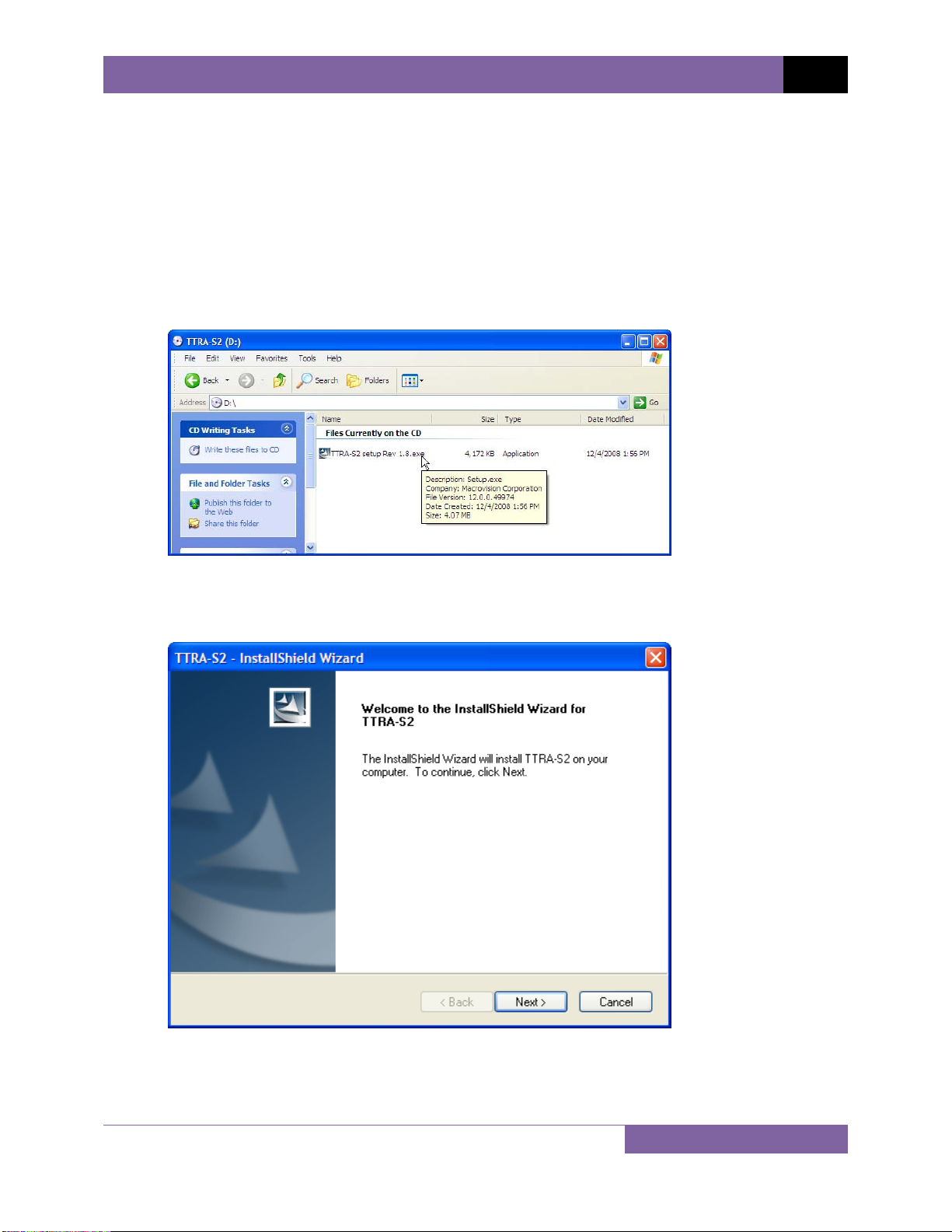
4. Double click (or single click in some Windows configurations) on your CD/DVD Drive icon
to navigate the installation CD. The contents of the CD will be listed as shown below:
5. Double click (or single click in some Windows configurations) on the “TTRA-S2 setup Rev
1.x.exe” file to start the installation process. The TTRA-S2 InstallShield Wizard will
appear as shown below:
3
Page 7
REV 2 TTRA-S2 VERSION 1.x SOFTWARE MANUAL
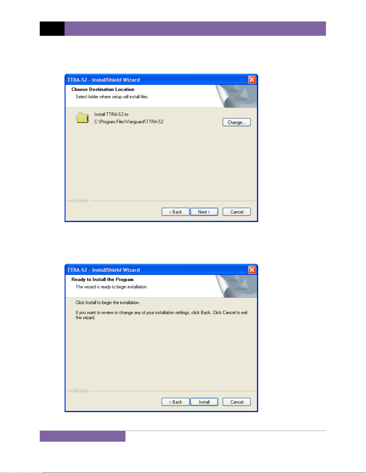
6. Click on the “Next” button to continue. The following screen will be displayed showing
the location on your hard drive where the software will be installed (C:\Program
Files\Vanguard\TTRA-S2):
7. You may choose a different installation location by clicking on the “Change…” button
and then browsing to the location on your hard drive where you would like to install the
software. If you would like to install the software in the default location, click on the
“Next” button to continue. The following screen will be displayed:
4
Page 8
TTRA-S2 VERSION 1.x SOFTWARE MANUAL REV 2
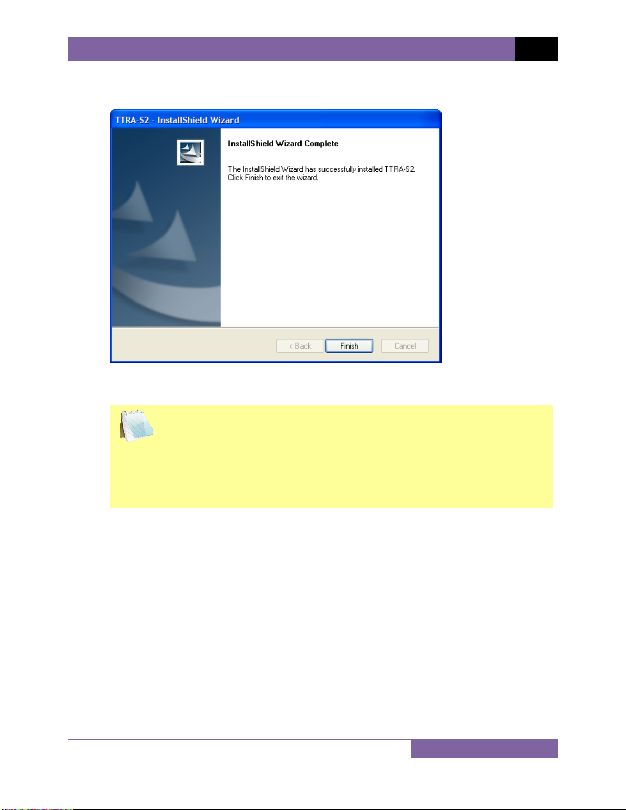
8. Click on the “Install” button. The InstallShield Wizard will copy files to your hard drive.
The following screen will be displayed once the software has been successfully installed:
9. Click on the “Finish” button to close the InstallShield Wizard and complete the
installation process.
• The installation program will create two sub-folders, “Test Plans” and
NOTES
“Test Records”, in the main installation folder. By default all test records
will be stored in the “Test Records” folder and all test plans will be
stored in the “Test Plans” folder.
• You can later change the default test record and test plan storage
locations. Please see section 3.2 for details.
5
Page 9
REV 2 TTRA-S2 VERSION 1.x SOFTWARE MANUAL
3.0 STARTING AND CONFIGURING THE TTRA-S2 SOFTWARE
During the installation process, a Vanguard program group will be created under the All
Programs submenu in the Windows Start menu. To launch the TTRA-S2 software:
1. Click on the Windows “Start” menu button to open the Start Menu.
2. Click on the All Programs menu item.
3. Click on the Vanguard menu item.
4. Click on the TTRA-S2 menu item.
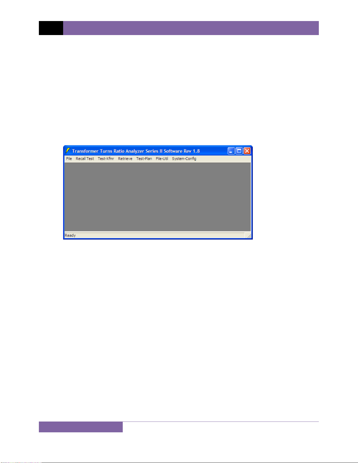
5. Click on the TTRA-S2 menu item. The TTRA-S2 main application window will appear as
shown below:
3.1 Main Menu Item Descriptions
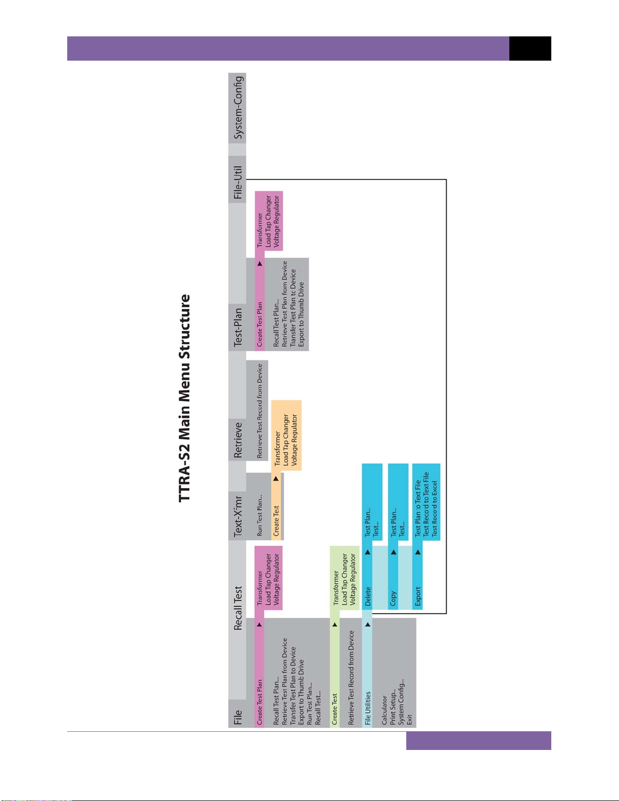
The TTRA-S2 Main Menu bar features the following menus:
• File Menu:
o Create, transfer, and run test plans
o Create and retrieve tests
o Configure system parameters and options
o Use various file utilities
o Use turns-ratio calculator
o Exit the program
• Recall Test Menu: Recall test records from the PC hard drive for viewing
• Test-Xfmr Menu:
o Run a test plan
o Create a transformer, load tap changer, or voltage regulator test plan
• Retrieve: Retrieve test records from an ATRT
• Test-Plan: Create, retrieve, modify, transfer, and export test plans
• File-Util: Copy, delete, and export test records and test plans
• Sys-Config: Configure system parameters
6
Page 10
TTRA-S2 VERSION 1.x SOFTWARE MANUAL REV 2
7
Page 11
REV 2 TTRA-S2 VERSION 1.x SOFTWARE MANUAL
3.2 System Configuration
Before using the program, the system configuration parameters should be reviewed and
changed as required. To configure the program settings:
1. Make sure the TTRA-S2 software is running on the PC.
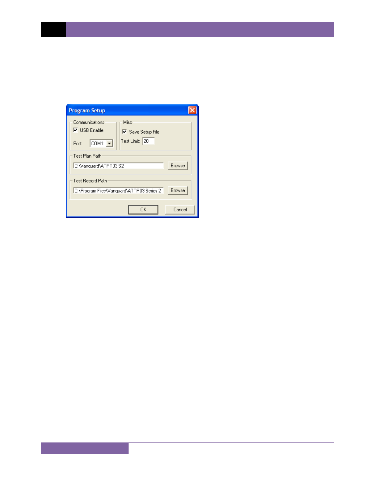
2. Click on the System-Config menu. The following window will be displayed:
a. Communications
If the ATRT is connected to the PC via the USB interface, make sure that the “USB
Enable” checkbox is checked.
If the ATRT is connected to the PC via the RS-232C interface, make sure to un-check
the “USB Enable” checkbox, and then select the correct RS-232C COM: port from the
“Port:” drop-down list.
b. Misc
Make sure the “Save Setup File” checkbox is checked if you would like to
permanently save the configuration settings. If this box is not checked, any settings
you change will only stay active for the current session and will be reset the next
time you run the software.
Type the number of tests that need to be run in the “Test Limit” input box. The test
limit defines the number of tests to be used in the transformer test plan. For
example, if the transformer has 10 tap positions, the test limit should be set to 10.
c. Test Plan Path
The default location where test plans are stored on the PC hard drive is listed in the
“Test Plan Path” section. You can change the default storage location by clicking on
the “Browse” button and then selecting a different folder.
8
Page 12
TTRA-S2 VERSION 1.x SOFTWARE MANUAL REV 2
d. Test Record Path
The default location where test records are stored on the PC hard drive is listed in
the “Test Record Path” section. You can change the default storage location by
clicking on the “Browse” button and then selecting a different folder.
3. Click on the “OK” button to apply all changes to the program settings.
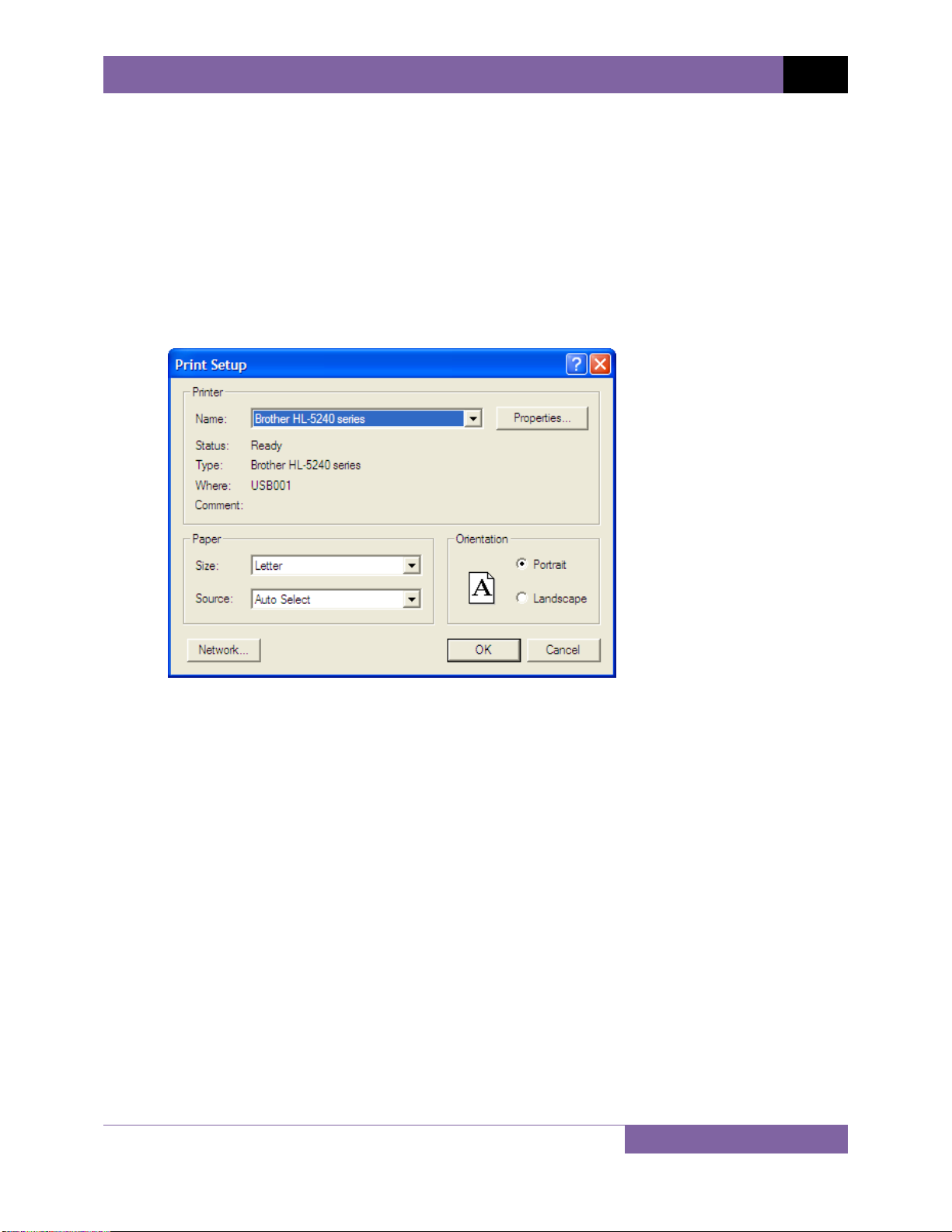
3.3 Printer Setup
To setup the printer:
1. Click on the File menu and select Print Setup… The following window will be displayed:
2. Select the printer you would like to use from the “Name” drop-down list.
3. Select the appropriate options for the printer.
4. Click on the “OK” button.
9
Page 13
REV 2 TTRA-S2 VERSION 1.x SOFTWARE MANUAL
4.0 WORKING WITH TEST RECORDS
The TTRA-S2 software can be used to retrieve test records from the ATRT or from the PC hard
drive. Once a test record is retrieved, you can change the record header settings, print the test
record, change the H Voltage, X Voltage, H Tap, and X Tap values, and save the record to the
hard drive.
If the H Voltage and/or X Voltage values are changed, the TTRA-S2 software will
automatically re-calculate the calculated ratio and deviation.
NOTE
4.1 Retrieving Test Records From an ATRT
To retrieve a test record from an ATRT:
1. Make sure the TTRA-S2 software is running. Connect the ATRT to the PC via either the
RS-232C port or the USB port and turn on the power.
2. From the Retrieve or File menu select Retrieve Test Record From Device.
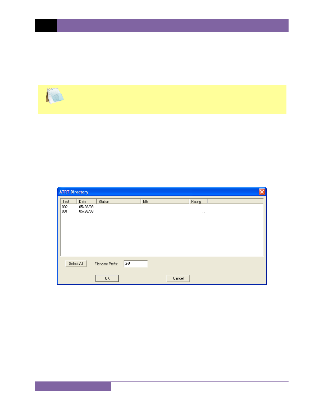
3. A window will appear listing a directory of all the test records stored in the ATRT’s
memory as shown:
4. You can select a test record to be retrieved by clicking on the test record number. The
selected record will be highlighted. You may select multiple records by holding down the
[CTRL] key and clicking on the record numbers. All selected records will be highlighted.
You may de-select a selected record by holding down the [CTRL] key and clicking on the
selected record number a second time. To select all of the test records, click on the
“Select All” button.
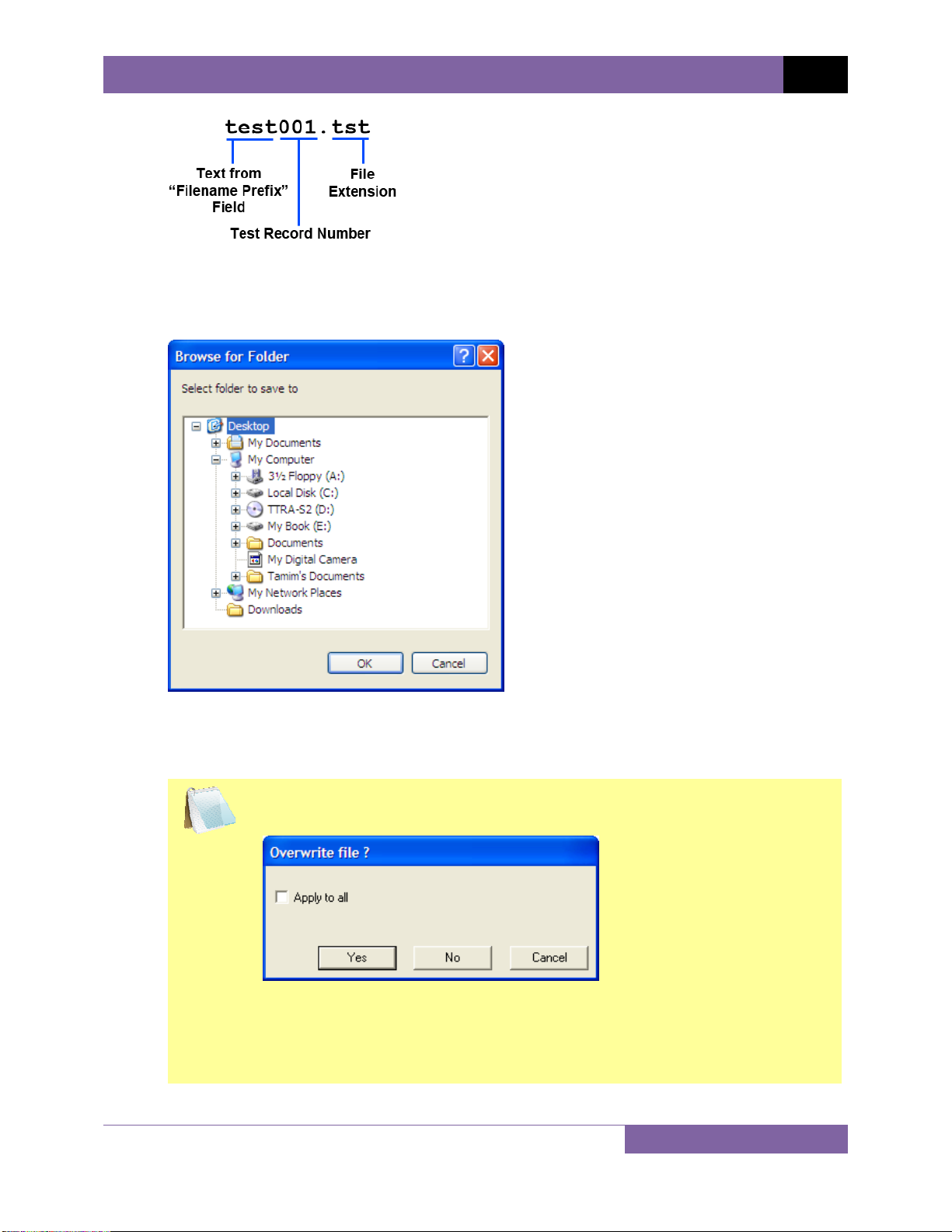
5. The “Filename Prefix” input field allows you to enter a word that will be used as part of
the filename for the stored record on the PC hard drive. When a test record is retrieved
from an ATRT and stored on the hard drive, the filename is in the following format:
10
Page 14
TTRA-S2 VERSION 1.x SOFTWARE MANUAL REV 2
So if you would like the filename to be “sample_test001.tst”, enter the word
sample_test in the “Filename Prefix” input field.
6. Click on the “OK” button. The following window will be displayed:
Browse to the location on your PC where you would like to save the retrieved test
records and click on the “OK” button. The test records will be retrieved from the ATRT
and saved to the selected location on your PC.
If a test record file with the same name already exists at the storage
location, the following window will be displayed:
NOTE
To overwrite the existing file, click on the “Yes” button. If you do not want
to overwrite the existing file with the retrieved test record, click on the
“No” button and you will be able to enter a different filename for the
retrieved test record.
11
Page 15
REV 2 TTRA-S2 VERSION 1.x SOFTWARE MANUAL
4.2 Recalling a Test Record From the PC Hard Drive
Test records stored on the PC hard drive can be recalled using the steps below:
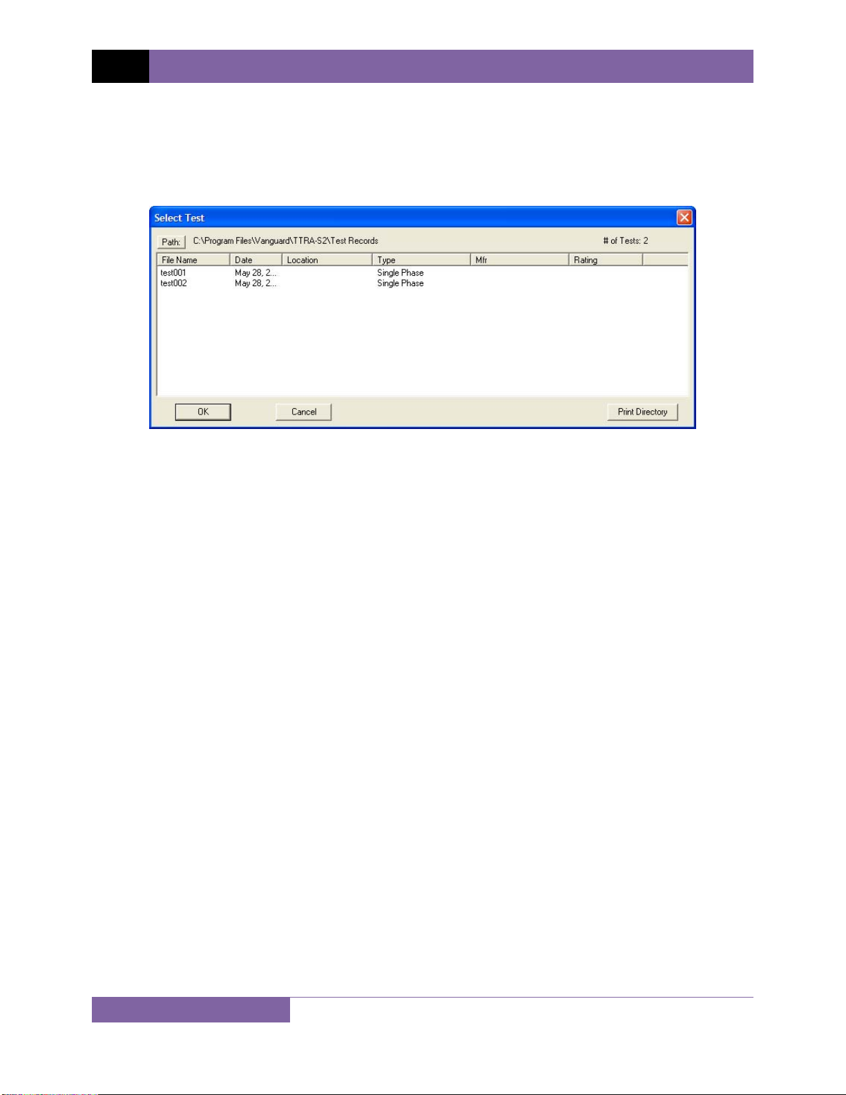
1. Click on the Recall Test menu (or click on the File menu and select Recall Test…). The
following window will be displayed:
• The top left section of the window displays the name of the directory where the test
records are being retrieved from. If you wish to retrieve records from a different
directory, click on the “Path” button and browse to the folder containing the test
records.
• The top right section of the window displays the total number of test records stored
in the current directory.
• If you would like to print the current directory listing, click on the “Print Directory”
button at the bottom of the window. Select the printer to print to and click on the
“OK” button.
2. Click on the filename you would like to retrieve and click the “OK” button. The test
record will be loaded and the tabulated test results will be displayed (please see section
4.8 for details).
12
Page 16

TTRA-S2 VERSION 1.x SOFTWARE MANUAL REV 2
4.3 Saving a Test Record
4.3.1. Saving a Test Record With Its Original Filename
1. If changes have been made to the current test record and you would like to save it with
its original filename, click on the Save menu and select Overwrite.
Alternatively, you can select the Save option from the File menu.
NOTE
2. The test record will be saved with its original filename.
4.3.2. Saving a Test Record With a Different Filename
1. To save an open test record with a different filename, click on the Save menu and select
Save As...
Alternatively, you can select the Save As... option from the File menu.
NOTE
The following window will be displayed:
2. Browse to the folder where you would like to save the test record.
3. Enter the filename in the “Filename:” input field.
4. Click on the “Save” button. The test record will be saved with the new filename.
13
Page 17

REV 2 TTRA-S2 VERSION 1.x SOFTWARE MANUAL
4.4 Copying Test Records
To copy a test record from one location on the PC hard drive to another location:
1. From the File-Util menu, click on Copy and then select Test (alternatively you can click
on the File menu, click on File Utilities, click on Copy and then select Test). The following
window will be displayed:
2. If the test record you would like to copy is not in the current directory, click on the
“Path” button at the top of the window and browse to the directory containing the file.
Once you have located the test record to be copied, click on the filename. You may
select additional test records by holding down the [CTRL] key and clicking on each
subsequent filename. Once you have selected the test record(s) to be copied, click on
the “OK” button. The following window will be displayed:
3. Browse to the folder where you would like the test record to be copied to, and then
click on the “OK” button. The test record will be copied to this folder with the same
filename as the original.
14
Page 18

TTRA-S2 VERSION 1.x SOFTWARE MANUAL REV 2
4.5 Deleting Test Records
To delete a test record stored on the PC hard drive:
1. From the File-Util menu, click on Delete and then select Test… (alternatively you can
click on the File menu, click on File Utilities, click on Delete, and then select Test…). The
following window will be displayed:
2. If the test record you would like to delete is not in the current directory, click on the
“Path” button at the top of the window and browse to the directory containing the file.
Once you have located the test record to be deleted, click on the filename. You may
select additional test records by holding down the [CTRL] key and clicking on each
subsequent filename. Once you have selected the test record(s) to be deleted, click on
the “OK” button. The selected test record(s) will be permanently deleted from the PC
hard drive.
15
Page 19

REV 2 TTRA-S2 VERSION 1.x SOFTWARE MANUAL
4.6 Exporting a Test Record in Microsoft® Excel® Format
You can export a test record in Microsoft® Excel® format. To export a test record in Excel®
format:
1. From the File-Util menu, click on Export and then select Test Record to Excel
(alternatively you can click on the File menu, click on File Utilities, click on Export, and
then select Test Record to Excel). The following window will be displayed:
2. If the test record you would like to export is not in the current directory, click on the
“Path” button at the top of the window and browse to the directory containing the file.
Once you have located the test record to be exported, click on the filename. You may
select additional test records by holding down the [CTRL] key and clicking on each
subsequent filename. Once you have selected the test record(s) to be exported, click on
the “OK” button. The following window will be displayed:
3. Browse to the folder where you would like the Excel
“OK” button. Figure 1 shows a test record in the TTRA-S2 software compared with the
exported data in Excel®.
16
®
file(s) to be saved and click on the
Page 20

TTRA-S2 VERSION 1.x SOFTWARE MANUAL REV 2
Figure 1. Test Record in TTRA-S2 Software and Microsoft Excel
17
Page 21

REV 2 TTRA-S2 VERSION 1.x SOFTWARE MANUAL
4.7 Exporting a Test Record to a Text File
You can also export a test record to a text file. To export a test record to a text file:
1. From the File-Util menu, click on Export and then select Test Record to Text File
(alternatively you can click on the File menu, click on File Utilities, click on Export, and
then select Test Record to Text File). The following window will be displayed:
2. If the test record you would like to export is not in the current directory, click on the
“Path” button at the top of the window and browse to the directory containing the file.
Once you have located the test record to be exported, click on the filename. You may
select additional test records by holding down the [CTRL] key and clicking on each
subsequent filename. Once you have selected the test record(s) to be exported, click on
the “OK” button. The following window will be displayed:
3. Browse to the folder where you would like the text file(s) to be saved and click on the
“OK” button.
18
Page 22

TTRA-S2 VERSION 1.x SOFTWARE MANUAL REV 2
Figure 2. Test Record in TTRA-S2 Software and in Text Format
19
Page 23

REV 2 TTRA-S2 VERSION 1.x SOFTWARE MANUAL
4.8 Working with Tabulated Test Results
Once a test record has been retrieved (see sections 4.1 and 4.2 for instructions), the record
details will be displayed as shown:
The menus on the menu bar will also change to provide additional options relevant to working
with a test record.
You can edit the test record header information (such as Company, Location,
Circuit, Operator, etc.) by entering data in the corresponding fields at the top of
NOTE
4.8.1. Printing the Tabulated Test Results
To print the tabulated test results:
1. Click on the Print menu. The print dialog box will appear.
2. Select the printer to print to and make any necessary changes to the printer’s
parameters and then click on the “OK” button. The test results will be printed. A sample
test record printout is shown in Figure 3.
the screen.
You can also edit the H Voltage, H Tap, X Voltage, and X Tap values. If these
values are changed, the calculated ratio and deviation will be automatically recalculated by the TTRA-S2 software.
20
Page 24

TTRA-S2 VERSION 1.x SOFTWARE MANUAL REV 2
Figure 3. A Typical Test Record Printout
21
Page 25

REV 2 TTRA-S2 VERSION 1.x SOFTWARE MANUAL
4.8.2. Displaying the Deviation Graph
The deviation graph is a useful tool for analyzing the transformer ratio deviation. The deviation
graph displays the phase A, B, and C turns-ratio deviation of the current test record. The
following formula is used to calculate the deviation, or percent difference:
Deviation = |[(Ratio
calculated
– Ratio
measured
)/ Ratio
calculated
] x 100|
To display the deviation graph for the loaded test record, click on the File menu and then select
the Display Deviation Graph option. A typical deviation graph is shown below in Figure 4.
Figure 4. A Typical Deviation Graph
22
Page 26

TTRA-S2 VERSION 1.x SOFTWARE MANUAL REV 2
5.0 WORKING WITH TEST PLANS
The TTRA-S2 software can be used to create transformer, load tap changer, and voltage
regulator test plans on the PC. Test plans can then be run from the PC or transferred to the
ATRT to be run from the ATRT (in stand-alone mode). Test plans can also be retrieved from the
ATRT using the TTRA-S2 software.
5.1 Retrieving Test Plans From an ATRT
To retrieve a test plan from an ATRT:
1. Make sure the TTRA-S2 software is running. Connect the ATRT to the PC via either the
RS-232C port or the USB port and turn on the power.
2. From the Test-Plan menu select Retrieve Test Plan From Device (alternatively you can
select Retrieve Test Plan From Device from the File menu).
3. A window will appear listing a directory of all the test plans stored in the ATRT’s
memory as shown:
4. You can select a test plan to be retrieved by clicking on the test plan number. The
selected test plan will be highlighted. You may select multiple test plans by holding
down the [CTRL] key and clicking on the test plan numbers. All selected test plans will
be highlighted. You may de-select a selected test plan by holding down the [CTRL] key
and clicking on the selected test plan number a second time. To select all of the test
plans, click on the “Select All” button.
5. The “Filename Prefix” input field allows you to enter a word that will be used as part of
the filename for the stored test plan on the PC hard drive. When a test plan is retrieved
from a ATRT and stored on the hard drive, the filename is in the following format:
23
Page 27

REV 2 TTRA-S2 VERSION 1.x SOFTWARE MANUAL
So if you would like the filename to be “sample_plan001.pln”, enter the word
sample_plan in the “Filename Prefix” input field.
6. Click on the “OK” button. The following window will be displayed:
Browse to the location on your PC where you would like to save the retrieved test plans
and click on the “OK” button. The test plans will be retrieved from the ATRT and saved
to the selected location on your PC.
24
Page 28

TTRA-S2 VERSION 1.x SOFTWARE MANUAL REV 2
5.2 Recalling a Test Plan From the PC Hard Drive
Test plans stored on the PC hard drive can be recalled using the steps below:
1. From the File menu or the Test-Plan menu, click on Recall Test Plan... The following
window will be displayed:
• The top left section of the window displays the name of the directory where the test
plans are being retrieved from. If you wish to retrieve test plans from a different
directory, click on the “Path” button and browse to the folder containing the test
plans.
• If you would like to print the current directory listing, click on the “Print Directory”
button at the bottom of the window. Select the printer to print to and click on the
“OK” button.
2. Click on the filename you would like to retrieve and click the “OK” button. The test plan
will be loaded and the test plan parameters will be displayed. You may change any of
the test plan parameters as needed.
25
Page 29

REV 2 TTRA-S2 VERSION 1.x SOFTWARE MANUAL
5.3 Transferring Test Plans to an ATRT
To transfer a test plan from the PC hard drive to an ATRT:
1. From the File menu or the Test-Plan menu, click on Transfer Test Plan to Device. The
following window will be displayed:
• The top left section of the window displays the name of the directory where the test
plans are being listed from. If you wish to transfer test plans from a different
directory, click on the “Path” button and browse to the folder containing the test
plans.
• If you would like to print the current directory listing, click on the “Print Directory”
button at the bottom of the window. Select the printer to print to and click on the
“OK” button.
2. Click on the filename you would like to transfer to the ATRT and click on the “OK”
button. The following window will be displayed showing a listing of the ATRT’s test plan
memory locations and their contents:
26
Page 30

TTRA-S2 VERSION 1.x SOFTWARE MANUAL REV 2
3. Click on the memory location where you would like the test plan to be transferred to
and click on the “OK” button. The test plan will be transferred to the ATRT’s memory.
If there are no empty memory locations available, you can select a memory
location with data in it, and it will be over-ridden with the transferred test
NOTE
plan.
27
Page 31

REV 2 TTRA-S2 VERSION 1.x SOFTWARE MANUAL
5.4 Saving a Test Plan
5.4.1. Saving a Test Plan With Its Original Filename
1. If changes have been made to the current test plan and you would like to save it with its
original filename, click on the Save menu and select Overwrite.
Alternatively, you can select the Save option from the File menu.
NOTE
2. The test plan will be saved with its original filename.
5.4.2. Saving a Test Plan With a Different Filename
1. To save the current test plan with a different filename, click on the Save menu and
select Save As...
Alternatively, you can select the Save As... option from the File menu.
NOTE
The following window will be displayed:
2. Browse to the folder where you would like to save the test plan.
3. Enter the filename in the “Filename:” input field.
4. Click on the “Save” button. The test plan will be saved with the new filename.
28
Page 32

TTRA-S2 VERSION 1.x SOFTWARE MANUAL REV 2
5.5 Copying Test Plans
To copy a test plan from one location on the PC hard drive to another location:
1. From the File-Util menu, click on Copy and then select Test Plan... (alternatively you can
click on the File menu, click on File Utilities, click on Copy and then select Test Plan...)
The following window will be displayed:
2. If the test plan you would like to copy is not in the current directory, click on the “Path”
button at the top of the window and browse to the directory containing the file. Once
you have located the test plan to be copied, click on the filename. You may select
additional test plans by holding down the [CTRL] key and clicking on each subsequent
filename. Once you have selected the test plan(s) to be copied, click on the “OK” button.
The following window will be displayed:
3. Browse to the folder where you would like the test plan to be copied to, and then click
on the “OK” button. The test plan will be copied to this folder with the same filename as
the original.
29
Page 33

REV 2 TTRA-S2 VERSION 1.x SOFTWARE MANUAL
5.6 Exporting Test Plans to a USB Thumb (Flash) Drive
You can export test plans to a USB thumb (Flash) drive for later use with an ATRT in stand-alone
mode.
1. Make sure your USB thumb drive is inserted in a USB port on your PC. Click on the File or
Test-Plan menu and select Export to Thumb Drive. The following window will be
displayed:
2. If the test plan you would like to export is not in the current directory, click on the
“Path” button at the top of the window and browse to the directory containing the file.
Once you have located the test plan to be exported, click on the filename. You may
select additional test plans by holding down the [CTRL] key and clicking on each
subsequent filename. Once you have selected the test plan(s) to be exported, click on
the “OK” button. The following window will be displayed:
30
Page 34

TTRA-S2 VERSION 1.x SOFTWARE MANUAL REV 2
3. Select your thumb drive and then click on the “OK” button. Do NOT select a folder in
your thumb drive since the TTRA-S2 software will create a “VANGUARD” folder in the
root of the thumb drive. The following window will be displayed:
4. Select the device that you will be using the thumb drive with, and then click on the “OK”
button. The selected test plan(s) will be exported to the thumb drive.
The TTRA-S2 software will create a “VANGUARD” folder in the root of your
thumb drive with two sub-folders, “ATRT03S2” and “TRI-PHS”. The test
NOTE
plan files will be exported to the sub-folder with the name corresponding
to the device you had selected. The filename will be in the format
“PLAN_xxx”, where “xxx” is an auto-incremented number.
31
Page 35

REV 2 TTRA-S2 VERSION 1.x SOFTWARE MANUAL
5.7 Deleting Test Plans
To delete a test plan stored on the PC hard drive:
1. From the File-Util menu, click on Delete and then select Test Plan... (alternatively you
can click on the File menu, click on File Utilities, click on Delete, and then select Test
Plan...). The following window will be displayed:
2. If the test plan you would like to delete is not in the current directory, click on the
“Path” button at the top of the window and browse to the directory containing the file.
Once you have located the test plan to be deleted, click on the filename. You may select
additional test plans by holding down the [CTRL] key and clicking on each subsequent
filename. Once you have selected the test plan(s) to be deleted, click on the “OK”
button. The selected test plan(s) will be permanently deleted from the PC hard drive.
32
Page 36

TTRA-S2 VERSION 1.x SOFTWARE MANUAL REV 2
5.8 Exporting a Test Plan to a Text File
You can export a test plan to a text file by using the steps below:
1. From the File-Util menu, click on Export and then select Test Plan to Text File
(alternatively you can click on the File menu, click on File Utilities, click on Export, and
then select Test Plan to Text File). The following window will be displayed:
2. If the test plan you would like to export is not in the current directory, click on the
“Path” button at the top of the window and browse to the directory containing the file.
Once you have located the test plan to be exported, click on the filename. You may
select additional test plans by holding down the [CTRL] key and clicking on each
subsequent filename. Once you have selected the test plan(s) to be exported, click on
the “OK” button. The following window will be displayed:
3. Browse to the folder where you would like the text file(s) to be saved and click on the
“OK” button.
33
Page 37

REV 2 TTRA-S2 VERSION 1.x SOFTWARE MANUAL
5.9 Creating Test Plans
The TTRA-S2 software can be used to create test plans for transformers, load tap changers, and
voltage regulators.
5.9.1. Creating a Test Plan for a Transformer
To create a test plan for a transformer:
1. From the Test-Plan menu or the File menu, click on Create Test Plan, and then click on
Transformer. An empty test plan will be displayed as shown below:
2. Enter the header information in the top section. You can use the [Tab] key to move from
one input area to the next or you can click on the desired input area.
3. Click on the “Type:” drop-down list and select the transformer type. If applicable, click
on the “Group:” drop-down list and select the group.
4. You can set the maximum deviation percentage by clicking in the “Max. Dev. %” input
area and typing in the desired value.
When using a test plan to run the turns-ratio test, the measured turns-ratio
is compared against the calculated turns-ratio. The difference (deviation)
NOTE
34
between the two turns-ratios is calculated as the percentage difference (see
section 4.8.2 for the formula). A deviation greater than the preset “Max.
Dev. %” will be marked as “F” (Fail) in the “P/F” column.
Page 38

TTRA-S2 VERSION 1.x SOFTWARE MANUAL REV 2
5. To set the test voltage, click on the “Voltage:” drop-down list and select the desired test
voltage (8 Vac, 40 Vac, or 100 Vac).
6. Enter the “H Voltage”, “H Tap”, “X Voltage”, and “X Tap” values for the first row by
clicking on each cell and then typing the value. You can also click on a cell, enter the
value, and then press the [TAB] key to move to the next cell on the right. You can also
use the up and down arrow keys to move vertically. Once the “H Voltage” and “X
Voltage” values have been entered, the calculated ratio will be displayed in the “Calc.
Ratio” column.
7. You can set the number of tests in the test plan by clicking on the “Set # of Tests”
button. The following window will be displayed:
Enter the number of tests, and then click on the “OK” button. This number will
determine the number of tests (data rows) in the blank test plan.
8. Once all information has been entered, save the test plan (see section 5.4).
35
Page 39

REV 2 TTRA-S2 VERSION 1.x SOFTWARE MANUAL
5.9.2. Creating a Test Plan for a Load Tap Changer
To create a test plan for a load tap changer (LTC):
1. From the Test-Plan menu or the File menu, click on Create Test Plan, and then click on
Load Tap Changer. The following window will be displayed:
2. Enter the number of steps in the corresponding input box. This is the number of taps
above or below the neutral position of the tap changer. The test plan generated will
have this number of steps above and below neutral. The total number of steps will be
twice this number plus one (neutral).
3. Enter the fraction of 1% per step value in the corresponding input box. This defines how
each step voltage is raised or lowered. The value must be entered as a fraction.
4. Enter the H voltage at neutral. This is the high side voltage at neutral.
5. Enter the X voltage at neutral. This is the low side voltage at neutral.
6. Select the LTC tap location from the corresponding drop-down list. Select “Low” if the
LTC taps are located on the low side of the transformer winding. Select “High” if the LTC
taps are located on the high side of the transformer winding.
7. Enter the number of extra tests. This adds extra tests other than the ones automatically
generated by the TTRA-S2 program. An extra row will be added in the test plan for each
extra test.
36
Page 40

TTRA-S2 VERSION 1.x SOFTWARE MANUAL REV 2
8. Click on the “OK” button. An untitled test plan with the selected parameters will be
created and displayed as shown below:
9. Enter the header information in the corresponding input fields.
10. If you had entered a number other than 0 for additional tests, enter the values for each
additional test row (H Voltage, X Voltage, H Tap, and X Tap). You can also modify any of
the H Voltage, H Tap, X Voltage, and X Tap values in the other rows by clicking on the
corresponding cell and entering the new value.
11. Select the LTC type from the “Type:” drop-down list. If applicable, select the group from
the “Group:” drop-down list.
12. Enter the maximum deviation percentage in the “Max Dev. %” input field.
13. Select the test voltage from the “Voltage:” drop-down list.
14. Save the test plan (see section 5.4).
37
Page 41

REV 2 TTRA-S2 VERSION 1.x SOFTWARE MANUAL
5.9.3. Creating a Test Plan for a Voltage Regulator
To create a test plan for a voltage regulator:
1. From the Test-Plan menu or the File menu, click on Create Test Plan, and then click on
Voltage Regulator. The following window will be displayed:
2. Enter the number of steps in the corresponding input box. This is the number of taps
above or below the neutral position of the voltage regulator. The test plan generated
will have this number of steps above and below neutral. The total number of steps will
be twice this number plus one (neutral).
3. Enter the fraction of 1% per step value in the corresponding input box. This defines how
each step voltage is raised or lowered. The value must be entered as a fraction.
4. Enter the H voltage at neutral. This is the high side voltage at neutral.
5. Select the voltage regulator tap location from the corresponding drop-down list. Select
“Low” if the voltage regulator taps are located on the low side of the transformer
winding. Select “High” if the voltage regulator taps are located on the high side of the
transformer winding.
38
Page 42

TTRA-S2 VERSION 1.x SOFTWARE MANUAL REV 2
6. Click on the “OK” button. An untitled test plan with the selected parameters will be
created and displayed as shown below:
7. Enter the header information in the corresponding input fields.
8. Select the voltage regulator type from the “Type:” drown-down list. If applicable, select
the group from the “Group:” drop-down list.
9. Enter the maximum deviation percentage in the “Max Dev. %” input field.
10. Select the test voltage from the “Voltage:” drop-down list.
11. Save the test plan (see section 5.4).
39
Page 43

REV 2 TTRA-S2 VERSION 1.x SOFTWARE MANUAL
6.0 RUNNING TESTS
The TTRA-S2 software can be used to run transformer, load tap changer, and voltage regulator
tests directly from the PC. This is especially convenient when used in conjunction with a test
plan.
6.1 Running a Transformer Turns Ratio Test Using a Test Plan
Follow the steps below to perform a transformer turns ratio test using a test plan (the same
procedure also applies for performing load tap changer and voltage regulator tests):
1. Make sure the ATRT is properly connected to the PC either via the USB or RS-232C port.
Also ensure that the TTRA-S2 software is properly configured to use the selected
interface port. See section 3.2 for details.
2. Connect the H and X leads per the ATRT’s user’s manual.
3. Click on the Test-Xfmr menu and select Run Test Plan... The following window will be
displayed:
40
Page 44

TTRA-S2 VERSION 1.x SOFTWARE MANUAL REV 2
4. If the test plan you would like to use is not in the current directory, click on the “Path”
button at the top of the window and browse to the directory containing the file. Once
you have located the test plan to be used, click on the filename, and then click on the
“OK” button. The test plan will be loaded and the first test (first data row) will be
selected as shown below:
5. To run a test, click on the “Run Test” button at the bottom of the window. The TTRA-S2
will initiate the test. Once the test is finished, the measured turns ratio, excitation
current, and the phase angle measurement information will be filled in. If the test plan
contained the transformer’s nameplate voltages, the “percentage deviation” and “P/F”
columns will also be filled in.
6. You can enter the resistor value for each phase reading by clicking on the “Res” cell and
entering the value.
7. The header information can also be edited as needed.
8. You can perform the next test by clicking on the “Next Test” button. If you would like to
repeat the last test performed, click on the “Repeat Test” button.
41
Page 45

REV 2 TTRA-S2 VERSION 1.x SOFTWARE MANUAL
9. A notepad is also available for entering any relevant information about the test. To
access the notepad, click on the “Notepad” button. The following window will be
displayed:
Type your notes and then click on the “OK” button.
10. Once all tests have been performed, click on the File menu and select either Save or
Save As... to save the test record.
42
Page 46

TTRA-S2 VERSION 1.x SOFTWARE MANUAL REV 2
6.2 Running a Transformer Test Using the Create Test Option
The Create Test option from the Test-Xfmr menu can be used to quickly create a test plan for
running a test. To test a transformer using the Create Test option:
1. From the Test-Xfmr menu, click on Create Test and then select Transformer.
You can also select Load Tap Changer or Voltage Regulator to create a Load
Tap Changer or Voltage Regulator test respectively. You will then be asked
NOTE
for the relevant parameters for the test. Please see sections 5.9.2 and 5.9.3
for further information.
An untitled test plan will be displayed as shown below:
2. Fill in the header information.
3. Select the transformer type and group, if applicable, from the corresponding drop-down
lists.
4. Edit the Max. Dev. % value if necessary.
5. Select the test voltage from the “Voltage:” drop-down list.
6. Fill in the transformer nameplate voltages. The “Phase” and “Calc. Ratio” fields will be
filled in automatically.
7. Click on the “Run Test”, “Next Test” or “Repeat Test” button to test the transformer.
43
Page 47

REV 2 TTRA-S2 VERSION 1.x SOFTWARE MANUAL
8. Once all tests have been performed, click on the File menu and select either Save or
Save As... to save the test record.
44
Page 48

TTRA-S2 VERSION 1.x SOFTWARE MANUAL REV 2
7.0 USING THE TRANSFORMER TURNS RATIO CALCULATOR
The TTRA-S2 software features a turns ratio calculator that can be used to quickly calculate the
winding turns ratio of a transformer. To use the calculator:
1. Click on the File menu and select Calculator. The calculator window will be displayed as
shown below:
2. Type the H voltage and X voltage values in the corresponding fields.
3. Select the transformer type from the “Type:” drop-down list.
4. If desired, type a percentage value in the “Percent:” input field. This option calculates
the turns ratio at the specified percentage of the nameplate voltage. For example, if the
H nameplate voltage is 12,000V, the X nameplate voltage is 1200V, the transformer type
is single phase, and the percentage value of 80 is used, the turns ratio will be calculated
as:
Ratio = (VH / VX) x (Percent / 100)
= (12,000 / 1200) x (80 / 100)
= 8.00
5. Click on the “Calculate” button and the calculated ratio will be displayed to the right of
the “Ratio:” label.
45
Page 49

1520 S. Hellman Ave • Ontario, CA 91761 • USA
Phone: 909-923-9390 • Fax: 909-923-9391
www.vanguard-instruments.com
Copyright © 2009 by Vanguard Instruments Company, Inc.
TTRA-S2™ Version 1.x Software Manual • Revision 2.0 • June 15, 2009 • TA
 Loading...