

Page 1
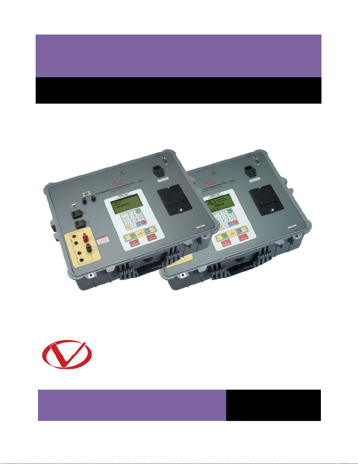
TRM-20 and TRM-40
TRANSFORMER RESISTANCE METERS
USER’S MANUAL
Vanguard Instruments Company, Inc.
1520 S. Hellman Ave.
Ontario, California 91761, USA
TEL: (909) 923-9390
FAX: (909) 923-9391
November 2011
Revision 1.2
Page 2

TRM-20 AND TRM-40 USER’S MANUAL REV 1
SAFETY SUMMARY
NOTICE
This manual applies to both the TRM-20 and TRM-40 transformer resistance meters. The
operating procedures are virtually the same for both models, and any differences are clearly
described where applicable.
FOLLOW EXACT OPERATING PROCEDURES
Any deviation from the procedures described in this User’s Manual may create one or more
safety hazards, may damage the TRM-20/40, damage the test transformer, or cause errors in
the test results. Vanguard Instruments Company, Inc. assumes no liability for unsafe or
improper use of the TRM-20/40.
All safety precautions provided in this manual must be observed during all phases of testing
including test preparation, test lead connection, actual testing, and test lead disconnection.
SAFETY WARNING AND CAUTIONS
The TRM-20/40 shall be used only by trained operators. All transformers under test shall be
off-line and fully isolated.
DO NOT MODIFY TEST EQUIPMENT
To avoid the risk of introducing additional or unknown hazards, do not install substitute parts or
perform any unauthorized modification to any TRM-20/40 test unit. To ensure that all designed
safety features are maintained, it is highly recommended that repairs be performed only by
Vanguard Instruments Company factory personnel or by an authorized repair service provider.
Unauthorized modifications can cause safety hazards and will void the manufacturer’s
warranty.
WARNING
Do not remove test leads during a test. Failure to heed this warning can result in electrical
shock to personnel and damage to the equipment.
i
Page 3

REV 1 TRM-20 AND TRM-40 USER’S MANUAL
TABLE OF CONTENTS
CONVENTIONS USED IN THIS DOCUMENT ..................................................................................... 1
1.0 INTRODUCTION .................................................................................................................. .. 2
1.1 General Description and Features ................................................................................... 2
1.2 Technical Specifications ................................................................................................... 4
1.3 TRM Controls and Indicators ........................................................................................... 5
2.0 PRE-TEST SETUP ................................................................................................................... 6
2.1 Operating Voltages .......................................................................................................... 6
2.2 LCD Screen Contrast Control ............................................................................................ 6
2.3 Printer Paper Control ....................................................................................................... 6
2.4 Printer Paper .................................................................................................................... 6
2.5 Replacing the Thermal Printer Paper ............................................................................... 7
3.0 OPERATING PROCEDURES ................................................................................................... 8
3.1 Configuring the LTCA Software for use with the TRM ..................................................... 8
3.2 Connecting the TRM to a PC via Bluetooth ................................................................... 10
3.3 Typical Connections to a Load Tap Changer (LTC) ......................................................... 17
3.4 Typical TRM-20/40 Cable Connections .......................................................................... 17
3.5 General Procedures ....................................................................................................... 19
3.6 Entering Test Record Header Information ..................................................................... 20
3.7 Setting the Date and Time ............................................................................................. 24
3.8 Setting the Interface Language ...................................................................................... 25
3.9 Performing a Resistance Test ......................................................................................... 26
3.10 Performing a Load Tap Changer / Voltage Regulator Resistance Test .......................... 35
3.11 Performing a Special Resistance Test ............................................................................ 44
3.12 Performing a Dynamic LTC Test ..................................................................................... 51
3.13 Performing a Diagnostic Test ......................................................................................... 56
3.14 Demagnetizing the Transformer Core ........................................................................... 58
3.15 Working with Test Records ............................................................................................ 60
3.15.1. Viewing the Contents of the Working Memory ..................................................... 60
3.15.2. Saving Test Results to a Test Record ...................................................................... 62
3.15.3. Restoring a Test Record From Flash EEPROM ........................................................ 64
3.15.4. Restoring a Test Record From a USB Flash Drive ................................................... 68
3.15.5. Copying Test Records to a USB Flash Drive ............................................................ 70
3.15.6. Printing a Test Record Directory ............................................................................ 73
3.15.7. Erasing Test Records from the Flash EEPROM ....................................................... 75
3.16 Erasing Test Records from a USB Flash Drive ................................................................ 78
3.17 Converting Resistance Measurements .......................................................................... 81
ii
Page 4

TRM-20 AND TRM-40 USER’S MANUAL REV 1
LIST OF FIGURES
Figure 1. TRM-20/40 Controls and Indicators ................................................................................ 5
Figure 2. Typical Connections to a Load Tap Changer (LTC) ......................................................... 17
Figure 3. Typical TRM Connections Diagram for A Dynamic Resistance Test .............................. 17
Figure 4. Typical TRM Connections Diagram for 2 Windings ........................................................ 18
Figure 5. Typical Resistance Test Results Printout........................................................................ 34
Figure 6. Typical LTC/Voltage Regulator Test Report Printout ..................................................... 43
Figure 7. Typical Special Test Report Printout .............................................................................. 50
Figure 8. Typical Dynamic LTC Test Results Printout Showing an Opened Circuit ....................... 55
Figure 9. Typical Test Record Directory Printout .......................................................................... 74
LIST OF TABLES
Table 1. TRM-20/40 Technical Specifications ................................................................................. 4
iii
Page 5
REV 1 TRM-20 AND TRM-40 USER’S MANUAL
CONVENTIONS USED IN THIS DOCUMENT
This document uses the following conventions:
• Both the TRM-20 and TRM-40 are simply referred to as “TRM” in this manual. The exact
model number is used only in cases where differences between the units are discussed.
• A key, switch, or knob on the TRM is indicated as [KEY], [SWITCH], [KNOB].
Menu names are referenced as “MENU NAME”
•
• TRM LCD screen output is shown as:
1. OPTION 1
2. OPTION 2
3. OPTION 3
4. OPTION 4
5. OPTION 5
• When instructions are provided, the menu item that should be selected is printed in bold as
shown below (option 3 should be selected in this example):
1. OPTION 1
2. OPTION 2
3. OPTION 3
4. OPTION 4
5. OPTION 5
• Warning messages are indicated as:
Warning message
WARNING
• Important notes are indicated as:
Note details
NOTE
1
Page 6

TRM-20 AND TRM-40 USER’S MANUAL REV 1
1.0 INTRODUCTION
1.1 General Description and Features
The TRM-20 and TRM-40 are Vanguard Instruments’ third generation transformer winding
resistance meters. The TRM line is designed specifically to measure DC resistance values of
transformer windings, rotating machine windings, or any dc resistance of an inductive device.
The TRM line features dual resistance-reading input channels that can measure two winding
resistances simultaneously (primary and secondary windings of a transformer).
Both the TRM-20 and TRM-40 can provide a fast and stable reading of very large transformers
by utilizing a 60Vdc power supply. The TRM-20 is capable of outputting a selectable test current
from 1A to 20A while the TRM-40’s test current is selectable from 1A to 40A.
Since the TRM-20 and TRM-40 can accurately measure resistance values from 1 micro-ohm to
2,000 Ohms, they can be used as micro-ohm meters to measure EHV circuit breaker contact
resistance, or for any low resistance measuring application.
If the transformer winding resistance temperature is available at the time of testing, the TRM
can calculate the equivalent resistance value at any temperature value. This useful feature
allows the user to compare the field readings against the factory test resistance values.
A special test mode allows the TRM to collect data automatically for up to 90minutes (at 60second sampling interval) or 45 minutes (at 30 second sampling interval). Test data is recorded
with a time stamp.
All test results can be printed on a 2.5” wide thermal printer. Test record header information
including the company, substation name, transformer information can also be entered using
the 16-key key pad.
The TRM-20 and TRM-40 can also demagnetize the inductive device under test, eliminating the
manual task of demagnetizing the transformer core after a resistance test.
The TRM also has a “make-before-break” test mode that can be used to test the load tap
changer (LTC) or voltage regulator test sequence. The TRM produces a “Dynamic-Resistance”
graph of the LTC or voltage regulator contact under operation. An opened contact can be
detected visually from this resistance chart.
The TRM’s built-in LTC/Voltage regulator can be used to change the LTC/Voltage regulator tap
position from the TRM front panel.
Safety Features
The TRM automatically dissipates the energy stored in the transformer at the end of each test.
The discharge circuit will continue to work even if the TRM power supply is lost.
Test Record Storage
The TRM can store up to 100 test records internally. For external test record storage, the TRM
features a USB Flash drive interface port. Up to 999 test records can be stored on a connected
USB Flash drive.
2
Page 7

REV 1 TRM-20 AND TRM-40 USER’S MANUAL
User Interface
The TRM features a back-lit graphic LCD screen (124x64) that is clearly viewable in both bright
sunlight and low-light levels. An alpha-numeric keypad is used to enter test information and to
operate the unit.
Computer Interfaces
The TRM can be connected to a PC via the unit’s RS-232C, USB, or Bluetooth interface. A PC can
be used to retrieve test records (stored in the TRM or USB Flash drive) or to run tests using the
provided software. Test records are automatically exported to PDF, Excel, and XML formats.
3
Page 8

1.2 Technical Specifications
Table 1. TRM-20/40 Technical Specifications
TYPE Portable transformer winding resistance meter
PHYSICAL SPECIFICATIONS 21” W x 17” H x 9” D (53 cm x 43 cm x 24 cm); Weight: 33 lbs (15.4Kg)
OPERATING VOLTAGE 100-240 Vac, 50/60 Hz
RESISTANCE READING
RANGE
ACCURACY 1 – 19,999 micro-ohms: ±0.5% reading, ±1 count;
TEST CURRENT 1-20A in 1A increments (TRM-20); 1-40A in 1A increments (TRM40)
TEST VOLTAGE 60Vdc charging, 18V DC max during measurement
RESISTANCE CHANNELS Two static resistance reading channels
DISPLAY Back-lit LCD (64 x 128 dot graphic), viewable in direct sunlight and low
PRINTER Built-in 2.5” wide thermal printer
INTERNAL TEST RECORD
STORAGE
EXTERNAL TEST RECORD
STORAGE
COMPUTER INTERFACES RS-232C, USB, and Bluetooth
SAFETY Designed to meet UL 61010A-1 and Can/CSA C22.2 No 1010.1092
ENVIRONMENT Operating: -10˚C to 50˚ C (15˚F to +122˚ F); Storage: -30˚ C to 70˚ C (-
HUMIDITY (MAX) 90% RH @ 40° C (104° F) non-condensing
ALTITUDE (MAX) 2000m (6562 ft) to full safety specifications
CABLES One 50-foot current cable set, two 50-foot resistance sense cable set, one
OPTIONS Transportation Case
WARRANTY One year on parts and labor
1 micro-ohm – 2000 Ohms (TRM-20);
1 micro-ohm to 500 Ohms (TRM-40)
20 – 999 milliohms: ±1% reading, ±1 count;
1 -2000 Ohms: ±1.5% reading, ±1 count
light levels
100 test records. Each record can contain up to 99 readings.
Up to 999 test records on external USB Flash drive.
standards
22˚F to +158˚ F)
LTC control cable, one ground cable, one power cord, One RS-232C
cable, one USB cable
TRM-20 AND TRM-40 USER’S MANUAL REV 1
The above specifications are valid at nominal operating voltage and at a
temperature of 25°C (77°F). Specifications may change without prior notice.
NOTE
4
Page 9
REV 1 TRM-20 AND TRM-40 USER’S MANUAL
1.3 TRM Controls and Indicators
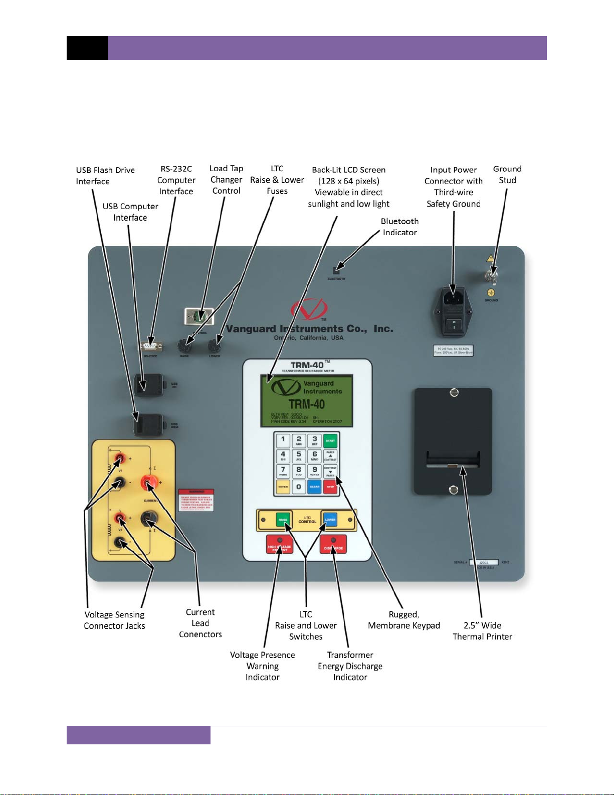
The TRM-20/40’s controls and indicators are shown in Figure 1. The purpose of the controls and
indicators may seem obvious, but users should become familiar with them before using the
TRM. Accidental misuse of the controls will usually cause no serious harm. Users should also be
familiar with the safety summary found on the front page of this User’s Manual.
5
Figure 1. TRM-20/40 Controls and Indicators
Page 10

TRM-20 AND TRM-40 USER’S MANUAL REV 1
2.0 PRE-TEST SETUP
2.1 Operating Voltages
The TRM’s operating voltages are 90-240 Vac, 50/60 Hz.
2.2 LCD Screen Contrast Control
To increase the LCD screen contrast, press and hold the [PAPER ∧ Contrast] key for two
seconds.
To decrease the LCD screen contrast, press and hold the [PAPER ∨ Contrast] key for two
seconds.
2.3 Printer Paper Control
To advance the TRM printer paper, press and release the [PAPER ∧ Contrast] key.
To retract the TRM printer paper, press and release the [PAPER ∨ Contrast] key.
2.4 Printer Paper
The TRM’s built-in thermal printer uses 2.5-inch wide thermal paper for printing test results. To
maintain the highest print quality and to avoid paper jams, the use of thermal paper supplied
by Vanguard Instruments Company is highly recommended. Additional paper can be ordered
from the following sources:
Vanguard Instruments Co, Inc.
1520 S. Hellman Avenue
Ontario, CA 91761
Tel: 909-923-9390
Fax: 909-923-9391
Part Number: VIC TP-3 paper
BG Instrument Co.
13607 E. Trent Avenue
Spokane, WA 99216
Tel: 509-893-9881
Fax: 509-893-9803
Part Number: VIC TP-3 paper
6
Page 11

REV 1 TRM-20 AND TRM-40 USER’S MANUAL
2.5 Replacing the Thermal Printer Paper
The roll of thermal paper is housed inside a dispenser underneath the printer cover. To replace
the paper, follow the steps below:
• Unscrew the two large printer cover screws and remove the printer cover.
• Remove the leftover thermal paper roll from the paper holder.
• Unroll the new thermal paper roll.
• Feed the thermal paper into the slot between the paper pocket and the rubber roller.
The printer will automatically pull the paper under the thermal head.
• Place the paper roll into the paper holder.
• Lift the thermal head and align the thermal paper if necessary.
• Re-install the printer cover.
Thermal paper has a chemical coating on one side of the paper. This side should be
facing the thermal print head. Incorrect paper loading may result in blank output on
NOTE
the thermal paper.
The thermal paper will show a red stripe to indicate that the roll is about to run out
of paper.
7
Page 12
TRM-20 AND TRM-40 USER’S MANUAL REV 1
3.0 OPERATING PROCEDURES
3.1 Configuring the LTCA Software for use with the TRM
The TRM can be used with a PC using the Vanguard LTCA software. Follow the steps below to
properly connect the TRM and configure the LTCA application to recognize the unit.
a. Install the LTCA software (please see the LTCA software user’s manual for details).
b. Connect the TRM to the PC by connecting a USB cable from an open USB port on the PC
to the unit’s “USB PC” port.
c. Turn on the power on the TRM.
d. If this is the first time you are connecting the unit to the PC, Windows will recognize it as
a new device and automatically install necessary drivers. If using Windows XP, you may
be prompted to install drivers. Select the automatic installation option and Windows will
locate the generic drivers necessary.
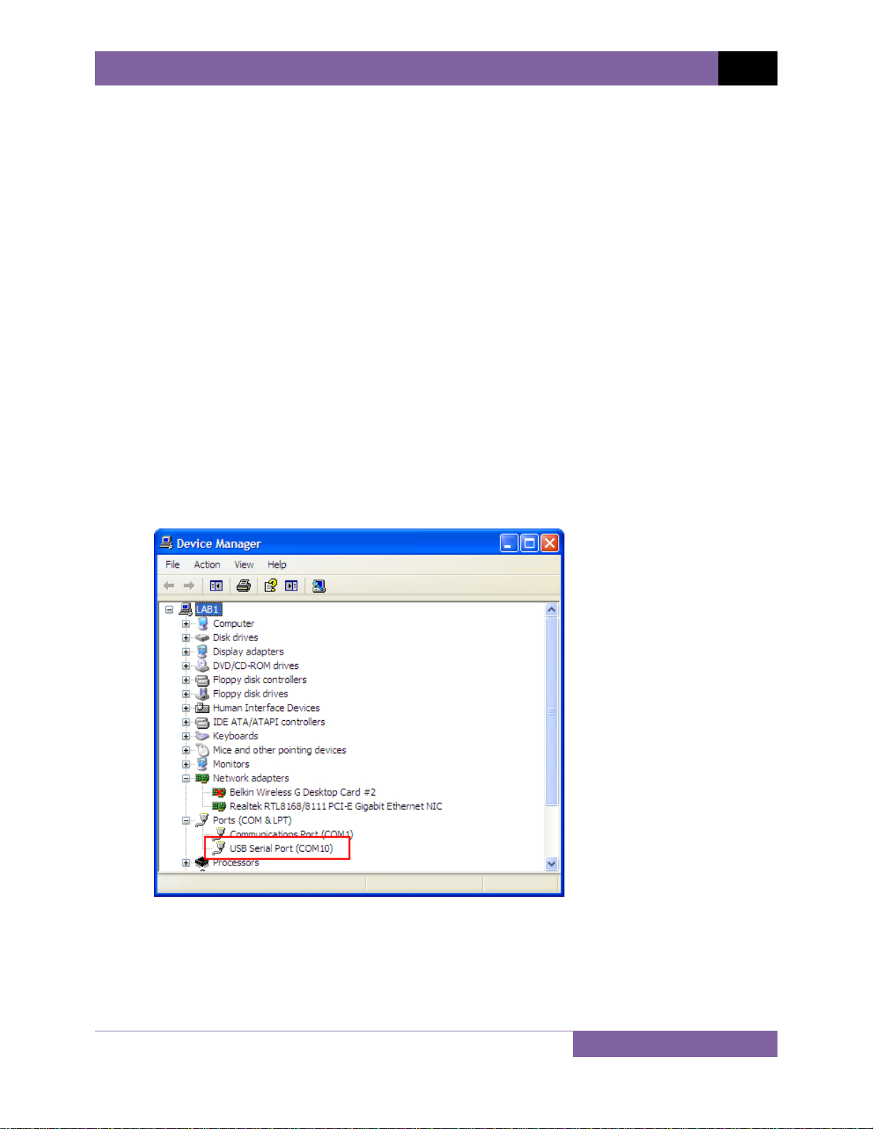
e. Please note that although the unit is connected via USB, it uses an internal serial
interface to communicate with the PC. As such, it will appear in the windows Device
Manager as a USB Serial Port. Open the Device Manager from the Windows Control
Panel and note the COM port number. For example, in the installation shown below, the
TRM is shown as COM10 (USB Serial Port).
8
Page 13
REV 1 TRM-20 AND TRM-40 USER’S MANUAL
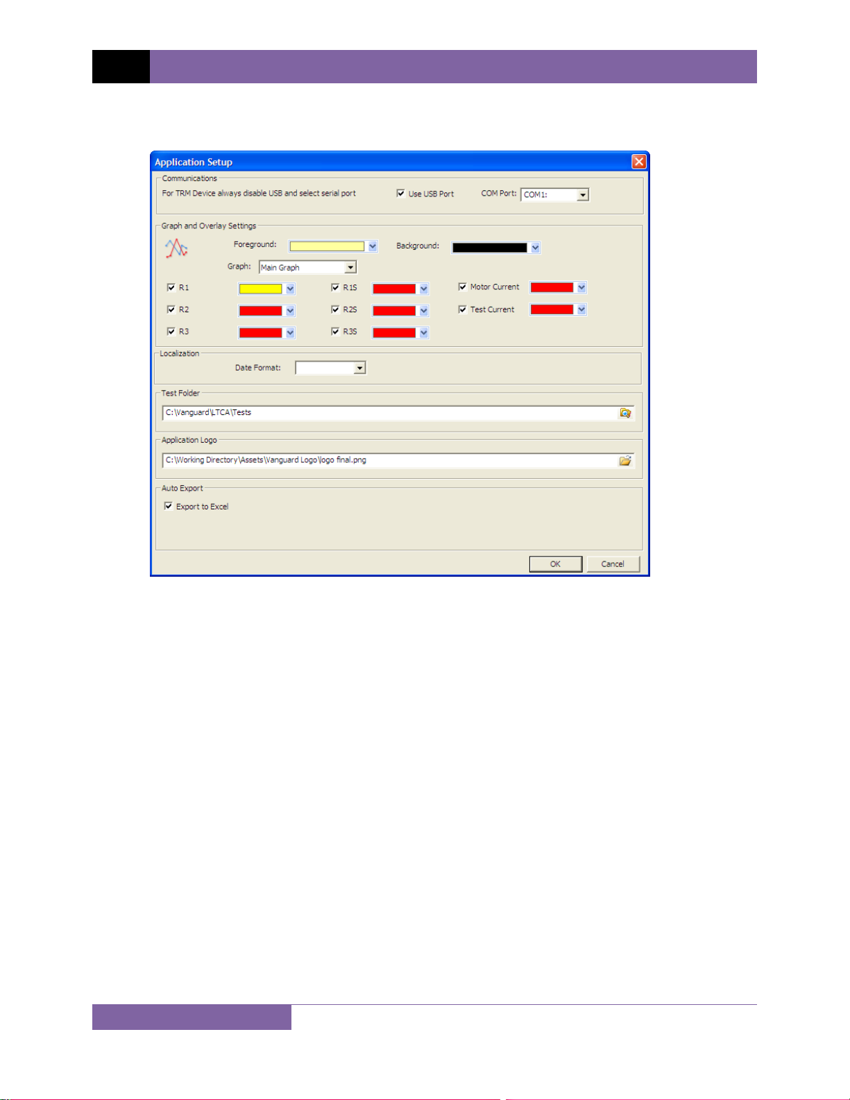
f. Launch the LTCA application and then click on the “Settings” icon. The following window
will be displayed:
Make sure the “User USB Port” is UN-checked. Then, from the “COM Port” drop-down
menu, select the COM port that corresponds to the port that the TRM is connected to.
Then click the OK button. The LTCA software will now recognize the TRM.
9
Page 14
TRM-20 AND TRM-40 USER’S MANUAL REV 1
3.2 Connecting the TRM to a PC via Bluetooth
The TRM can also be connected wirelessly to a PC using Bluetooth. To connect the unit via
Bluetooth, it must first be paired with the PC. Follow the steps below to pair the TRM to a PC
via Bluetooth:
For Windows XP:
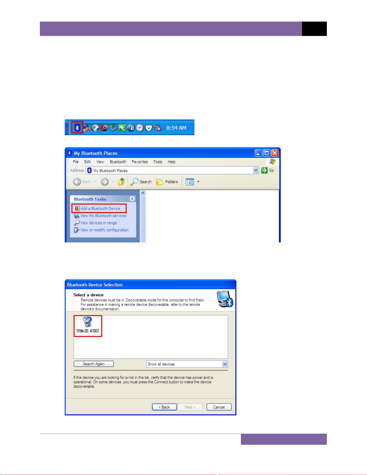
a. Make sure the TRM is turned on. Then double click on the Bluetooth system tray icon
(on the bottom right corner of your computer screen):
b. The “My Bluetooth Places” window will be displayed:
Click on “Add a Bluetooth Device” on the left window pane.
c. The Bluetooth Setup Wizard window will be displayed. Click on the “Next” button. The
PC will scan for nearby devices and list all available Bluetooth devices:
10
Page 15
REV 1 TRM-20 AND TRM-40 USER’S MANUAL
The TRM will be listed as “TRM S/N” where S/N is the device’s serial number. Click on
the icon for the TRM and then click on the “Next” button.
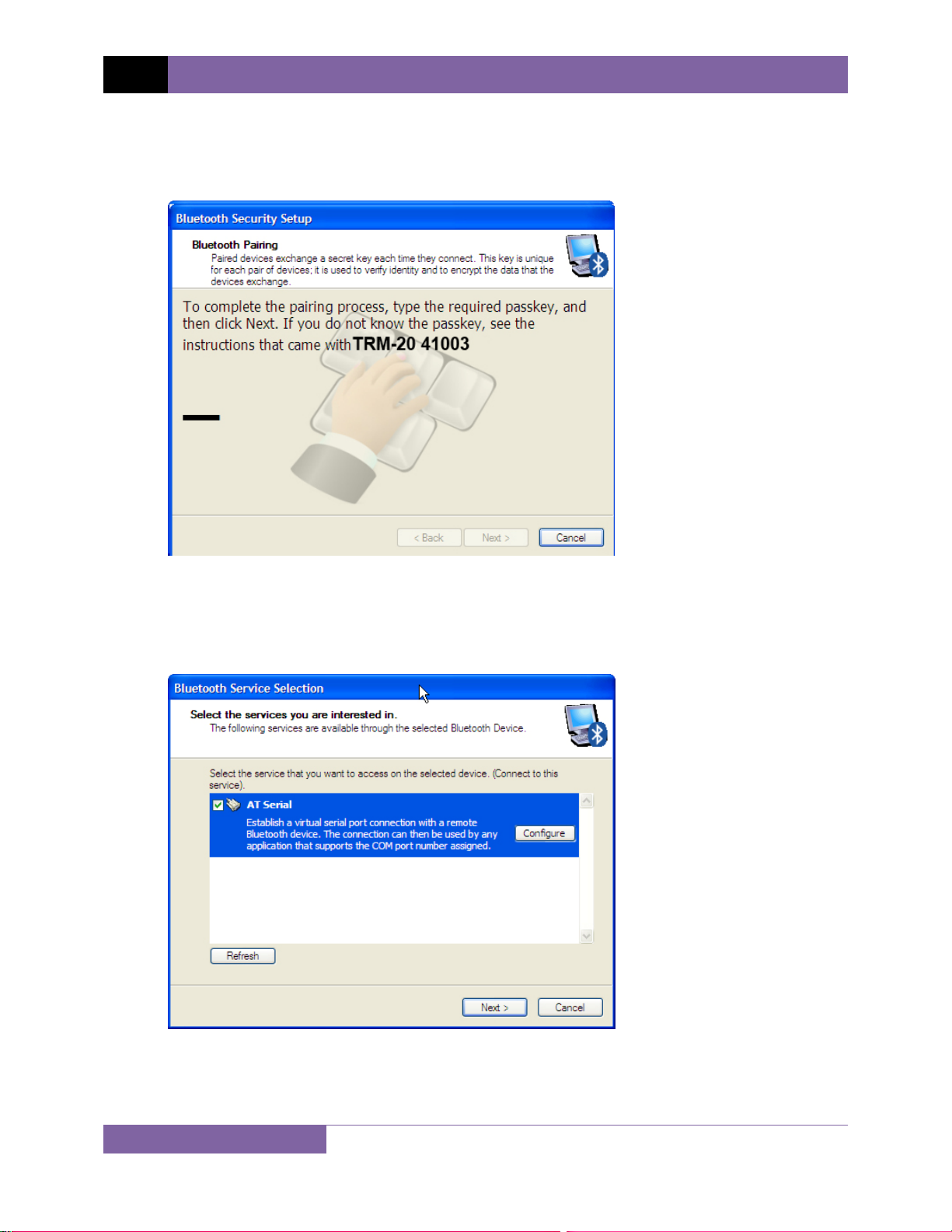
d. The following window will be displayed asking for a secret key to connect to the TRM:
Type the word “default” (without the quotes and in all lower-case) and then click on the
“Next” button.
e. The following window will be displayed with the option to connect to the TRM as a serial
port:
Make sure to check the box next to “AT Serial” and then click on the “Next” button.
11
Page 16
TRM-20 AND TRM-40 USER’S MANUAL REV 1
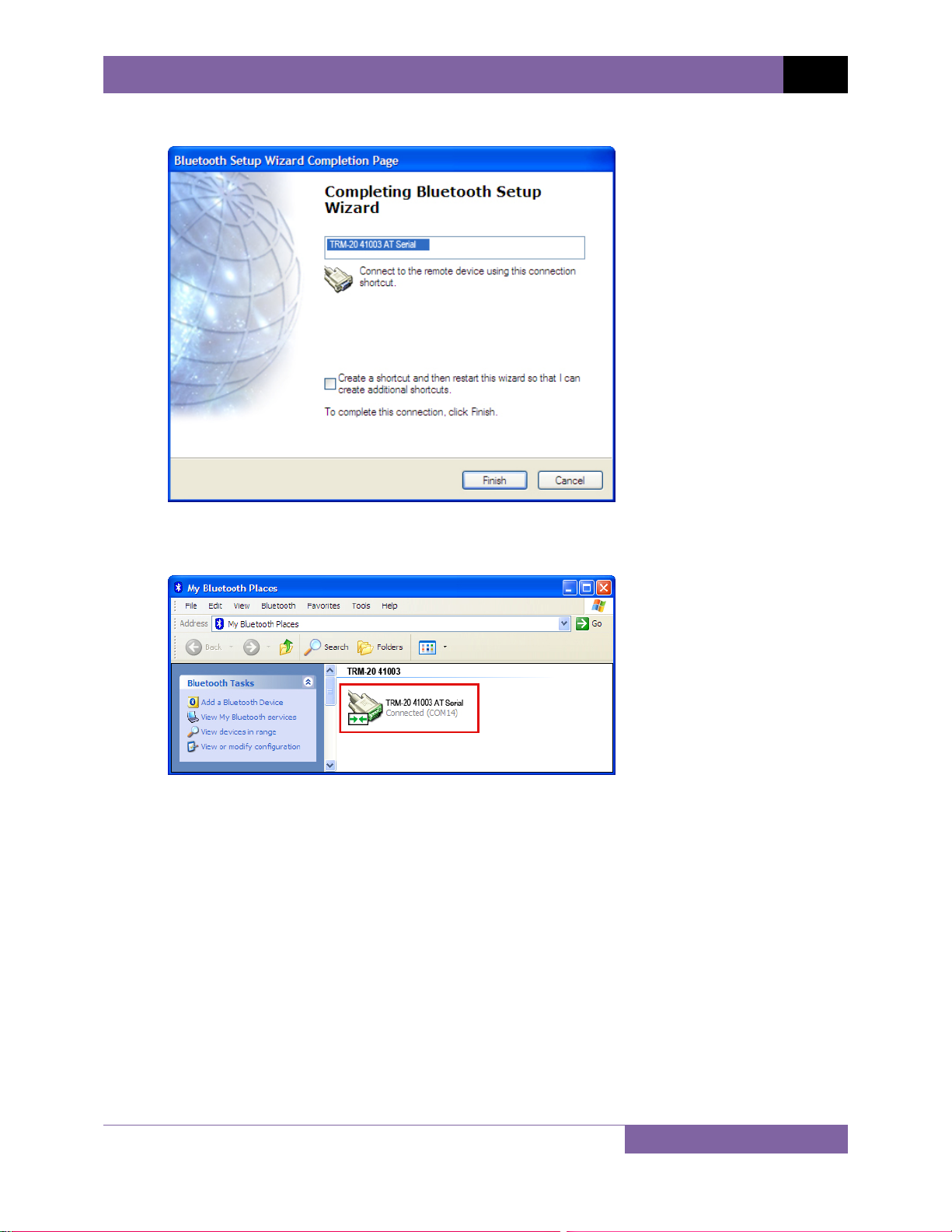
f. The following confirmation screen will be displayed:
Click on the “Finish” button.
g. The TRM-20 will now be displayed in the “My Bluetooth Places” window:
Note the port number listed under the device name. In the above case, the port number
is COM14. Use this port number in the LTCA software to connect to the TRM.
12
Page 17
REV 1 TRM-20 AND TRM-40 USER’S MANUAL
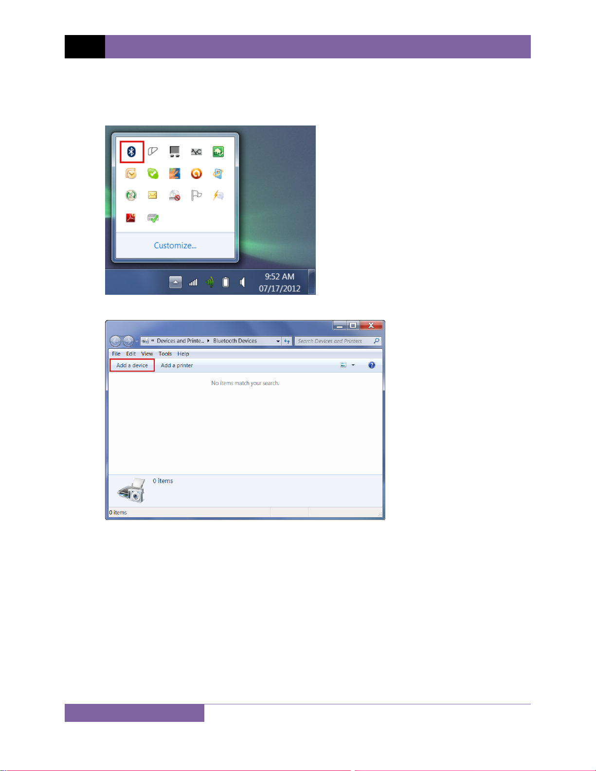
For Windows 7:
a. Make sure the TRM is turned on. Then double click on the Bluetooth system tray icon
(on the bottom right corner of your computer screen):
b. The “Bluetooth Devices” window will be displayed:
Click on “Add a device”.
13
Page 18
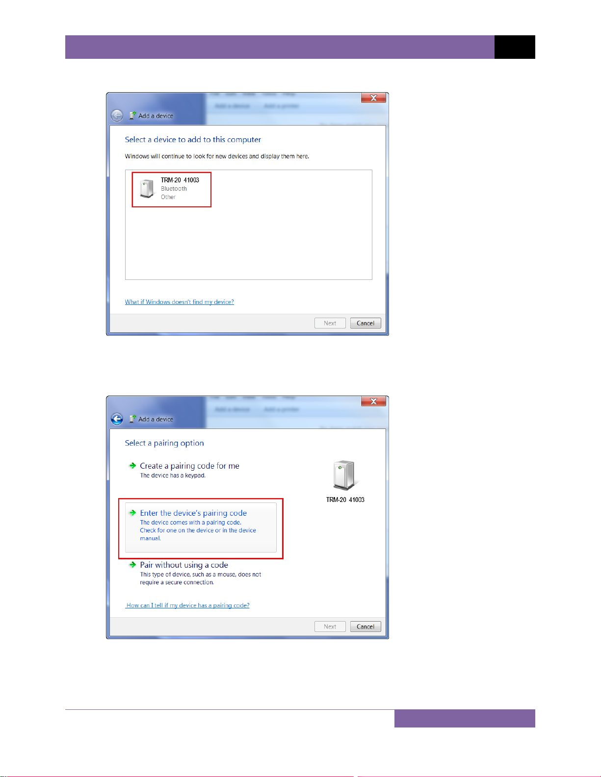
c. All nearby Bluetooth devices will be listed:
TRM-20 AND TRM-40 USER’S MANUAL REV 1
The TRM will be listed as “TRM S/N” where S/N is the device’s serial number. Click on
the icon for the TRM and then click on the “Next” button.
d. The device pairing screen will be displayed:
Click on “Enter the device’s pairing code” option.
14
Page 19
REV 1 TRM-20 AND TRM-40 USER’S MANUAL
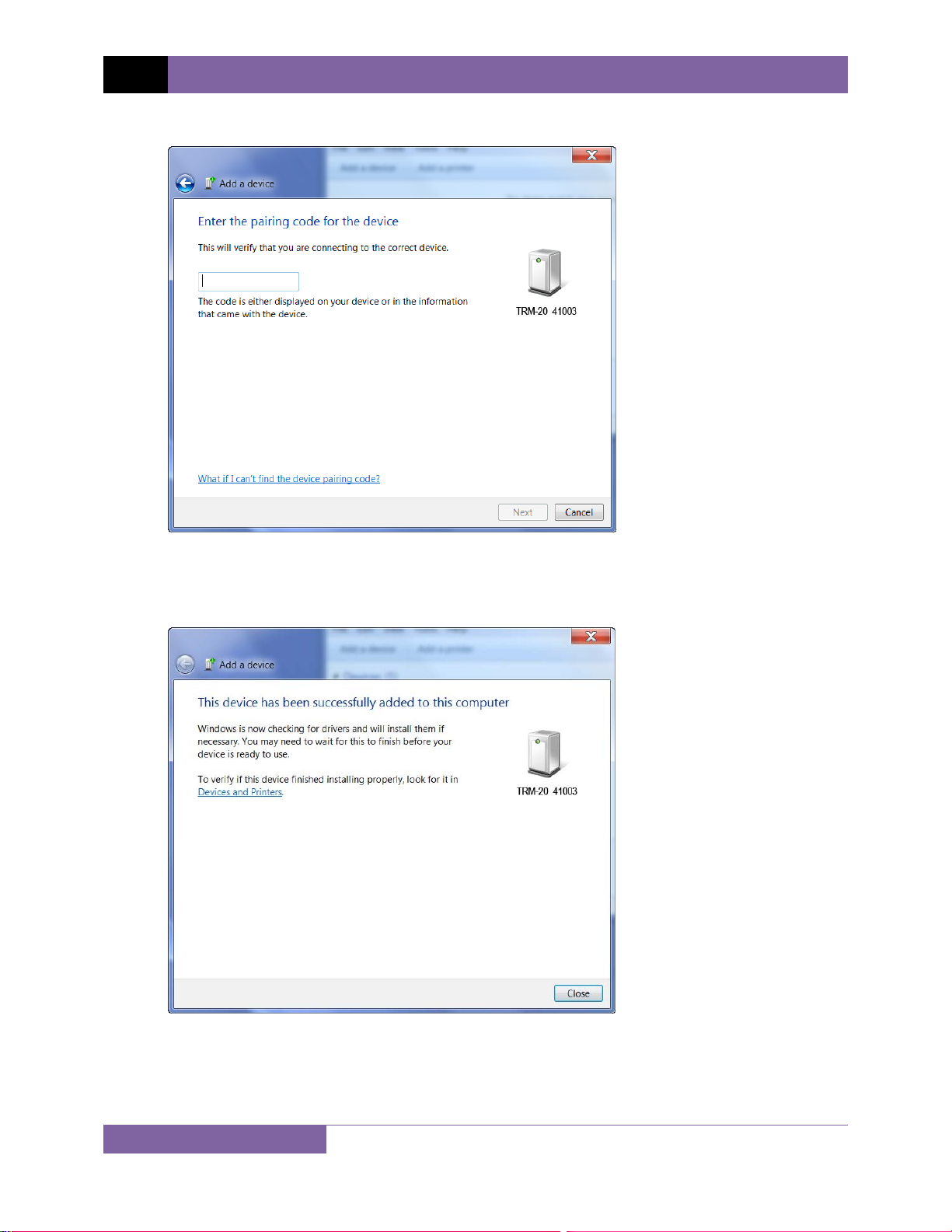
e. The following window will be displayed:
Type the word “default” (without the quotes and in all lower-case) in the text box and
click on the “Next” button.
f. The following screen will be displayed:
Click on the “Close” button.
15
Page 20
TRM-20 AND TRM-40 USER’S MANUAL REV 1
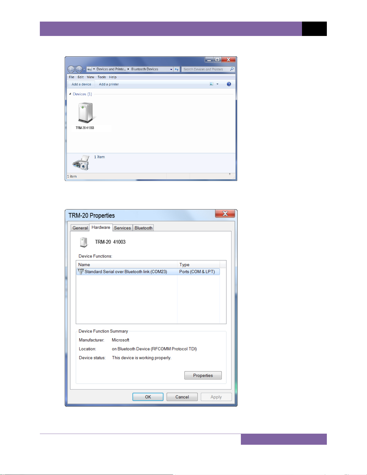
g. The TRM will now be listed under “Bluetooth Devices”:
Right click on the TRM-20 icon and select “Properties” from the pop-up menu.
h. The properties window will be displayed. Click on the “Hardware” tab:
Note the port number listed after the device name (COM23 in the above example). Use this
port number in the LTCA software to connect to the TRM.
16
Page 21
REV 1 TRM-20 AND TRM-40 USER’S MANUAL
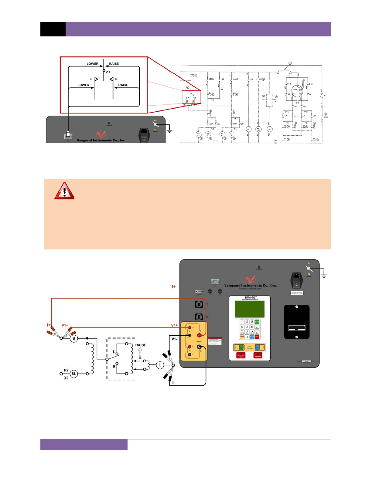
3.3 Typical Connections to a Load Tap Changer (LTC)
Figure 2. Typical Connections to a Load Tap Changer (LTC)
3.4 Typical TRM-20/40 Cable Connections
• Do not touch or disconnect any test lead that is connected to a transformer
WARNINGS
terminal while high current is being conducted during a test. Failure to heed
this warning can result in electric shock to personnel and/or damage to the
equipment.
• Disconnect the test clips from the transformer bushing only after the TRM
has completely discharged the transformer. Always disconnect the test clips
slowly from the transformer bushing to prevent an accidental flash-over.
Figure 3. Typical TRM Connections Diagram for A Dynamic Resistance Test
17
Page 22
TRM-20 AND TRM-40 USER’S MANUAL REV 1
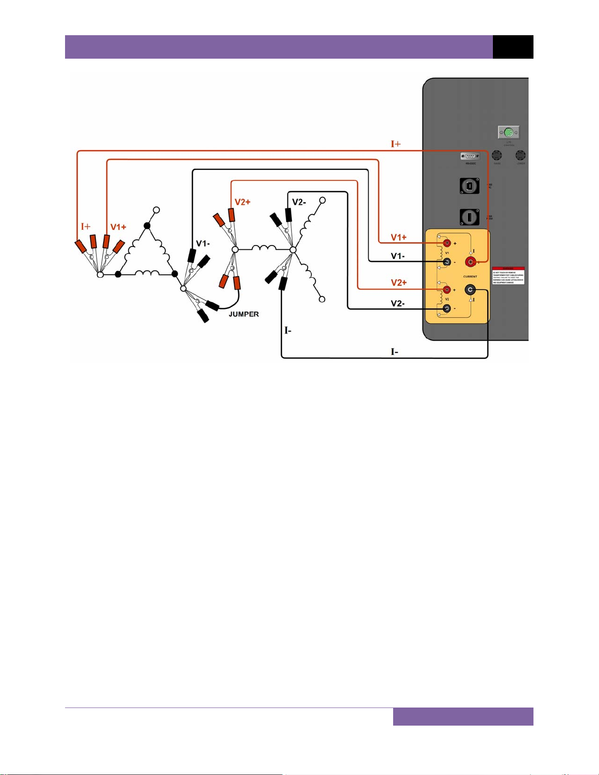
Figure 4. Typical TRM Connections Diagram for 2 Windings
18
Page 23

REV 1 TRM-20 AND TRM-40 USER’S MANUAL
3.5 General Procedures
The main steps for using the TRM are outlined below:
a. Ground the TRM to the substation ground.
Always connect the TRM to the substation ground before connecting any
test lead to any transformer bushing. Failure to follow this procedure may
WARNING
damage the TRM.
b. Plug the TRM power cable into a power outlet.
c. Insert current-cable plugs and voltage-sensing cable plugs into the corresponding
control panel jacks.
d. Attach the test cable clamps to the transformer terminal for the winding that is to be
measured.
e. Turn on the TRM.
f. The unit will self-calibrate, and then you will be presented with the “START-UP” menu as
shown below:
1. RUN TEST
2. SETUP
3. USER DIAGNOSTICS
11/01/11
09:06:21
22°C 72°F
19
Page 24

TRM-20 AND TRM-40 USER’S MANUAL REV 1
3.6 Entering Test Record Header Information
You can enter the test record header information before performing tests. The record header
includes identifying information such as the company, station, circuit, model number, etc. Once
the header information has been entered, it will apply to all subsequent test records. To enter
the header information:
a. Start from the “START-UP” menu:
1. RUN TEST
2. SETUP
3. USER DIAGNOSTICS
11/01/11
09:06:21
22°C 72°F
Press the [2] key (SETUP).
b. The following screen will be displayed:
1. RECORD ID
2. PRINT RECORD
3. SAVE/RESTORE RECORD
4. SET TIME
5. SET LANGUAGE
Press the [1] key (RECORD ID).
c. The following screen will be displayed:
COMPANY:
_
↑/↓ TO POSITION
"ENTER" TO ACCEPT
Type the company name using the alpha-numeric keypad.
When pressing a key, the corresponding number on the key will be displayed first.
Pressing the key again will display the first letter on the key. Pressing the key again will
display the second letter on the key. For example, to type the letter “A”, you must press
the [2] key twice. To erase the character at the cursor position, press the [CLEAR] key.
Press the [PAPER ∧ Contrast] key to move to the next character. Press the [PAPER
∨ Contrast]
key to move to the previous character. Press the [ENTER] key when you
are done typing the company name.
20
Page 25

REV 1 TRM-20 AND TRM-40 USER’S MANUAL
d. The following screen will be displayed:
STATION:
_
↑/↓ TO POSITION
"ENTER" TO ACCEPT
Type the station name using the alpha-numeric keypad and then press the [ENTER]
key.
e. The following screen will be displayed:
CIRCUIT:
_
↑/↓ TO POSITION
"ENTER" TO ACCEPT
Type the circuit information using the alpha-numeric keypad and then press the
[ENTER] key.
f. The following screen will be displayed:
MANUFACTURER:
_
↑/↓ TO POSITION
"ENTER" TO ACCEPT
Type the manufacturer name using the alpha-numeric keypad and then press the
[ENTER] key.
21
Page 26

g. The following screen will be displayed:
MODEL:
_
↑/↓ TO POSITION
"ENTER" TO ACCEPT
Type the model information using the alpha-numeric keypad and then press the
[ENTER] key.
h. The following screen will be displayed:
SERIAL NUMBER:
_
↑/↓ TO POSITION
"ENTER" TO ACCEPT
TRM-20 AND TRM-40 USER’S MANUAL REV 1
Type the serial number using the alpha-numeric keypad and then press the [ENTER]
key.
i. The following screen will be displayed:
KVA RATING:
_
↑/↓ TO POSITION
"ENTER" TO ACCEPT
Type the transformer’s KVA rating using the alpha-numeric keypad and then press the
[ENTER] key.
22
Page 27

REV 1 TRM-20 AND TRM-40 USER’S MANUAL
j. The following screen will be displayed:
OPERATOR:
_
↑/↓ TO POSITION
"ENTER" TO ACCEPT
Type the operator’s name using the alpha-numeric keypad and then press the [ENTER]
key.
All header information will be saved, and you will be returned to the “START-UP” menu.
23
Page 28

3.7 Setting the Date and Time
To set the date and time:
a. Start from the “START-UP” menu:
TRM-20 AND TRM-40 USER’S MANUAL REV 1
1. RUN TEST
2. SETUP
3. USER DIAGNOSTICS
Press the
[2] key (SETUP)
11/01/11
09:06:21
22°C 72°F
b. The following screen will be displayed:
1. RECORD ID
2. PRINT RECORD
3. SAVE/RESTORE RECORD
4. SET TIME
5. SET LANGUAGE
Press the
[4] key (SET TIME).
c. The following screen will be displayed:
ENTER DATE
MM-DD-YY
_
Type the current date using the keypad. The following screen will be displayed:
ENTER TIME
HH:MM:SS
_
Enter the time using the keypad. When the time has been entered, you will be
immediately returned to the “START-UP” menu.
24
Page 29

REV 1 TRM-20 AND TRM-40 USER’S MANUAL
3.8 Setting the Interface Language
Follow the steps below to set the interface language (English, Spanish, or Turkish):
a. Start from the “START-UP” menu:
1. RUN TEST
2. SETUP
3. USER DIAGNOSTICS
Press the
[2] key (SETUP).
11/01/11
09:06:21
22°C 72°F
b. The following screen will be displayed:
1. RECORD ID
2. PRINT RECORD
3. SAVE/RESTORE RECORD
4. SET TIME
5. SET LANGUAGE
Press the
[5] key (SET LANGUAGE).
c. The following screen will be displayed:
1. ENGLISH
2. TURKISH
3. SPANISH
Select the preferred interface language by pressing the corresponding key on the
keypad (
[1], [2], or [3]). The interface language will be set and a confirmation screen
will be displayed as shown below:
ENGLISH SET
Press any key to return to the “START-UP” menu.
25
Page 30

3.9 Performing a Resistance Test
a. Start from the “START-UP” menu:
TRM-20 AND TRM-40 USER’S MANUAL REV 1
1. RUN TEST
2. SETUP
3. USER DIAGNOSTICS
11/01/11
09:06:21
22°C 72°F
Press the [1] key (RUN TEST).
b. The following screen will be displayed:
1. RESISTANCE TEST
2. SPECIAL RES TEST
3. DYNAMIC LTC TEST
4. DEGAUSS WINDING
Press the [1] key (RESISTANCE TEST).
c. The following screen will be displayed:
LTC OR VTG REGULATOR?
1. YES
2. NO
Press the
[2] key (NO).
d. The following screen will be displayed:
1. V1, V2 RES TEST
2. V1 ONLY RES TEST
Press the
Press the
[1] key (V1, V2 RES TEST) if you would like to perform a V1 & V2 test.
[2] key (V1 ONLY RES TEST) if you would like to perform a V1 test only.
26
Page 31

REV 1 TRM-20 AND TRM-40 USER’S MANUAL
e. The following menu will be displayed:
SELECT TEST CURRENT:
1. 1A
2. 5A
3. 10A
4. 20A
5. 40A
6. CUSTOM
Select the test current by pressing the corresponding numeric key on the keypad. Press
the [6] key (CUSTOM) if you would like to enter a custom test current and then enter
the current (between 1A-40A) on the next screen.
f. The following screen will be displayed:
CONVERT READINGS TO
STANDARD TEMP?
1. YES
2. NO
1. YES
Press the [1] key (YES) if you wish to convert readings to standard temperature.
The following screen will be displayed:
WINDING MATERIAL:
1. COPPER, TK=234.5
2. ALUMINUM, TK=225.0
3. MANUALLY ENTER TK
Press the [1] key (COPPER, Tk=234.5) to select copper as the winding material.
Continue to step g.
Press the [2] key (ALUMINUM, Tk=225.0) to select aluminum as the winding
material. Continue to step g.
Press the
[3] key (MANUALLY ENTER Tk) to manually enter the Tk value. The
following screen will be displayed:
27
Page 32

TRM-20 AND TRM-40 USER’S MANUAL REV 1
TK:
230.0°C
↑↓ to adjust tk
"ENTER" to accept
You can increase the Tk value by 0.5°C increments by pressing the [PAPER ∧
Contrast]
key.
You can decrease the Tk value by 0.5°C increments by pressing the [PAPER ∨
Contrast]
key.
Press the
[ENTER] key to confirm the temperature setting. Continue to step g.
2. NO
Press the
[2] key (NO) if you do NOT wish to convert readings to standard
temperature. Continue to step i.
g. The following screen will be displayed:
D.U.T. TEMP:
25.0°C 77.0°F
↑↓ to adjust tk
"ENTER" to accept
Use the [PAPER ∧ Contrast] and [PAPER ∨ Contrast] keys to adjust the D.U.T.
(Device Under Test) temperature.
Press the
[ENTER] key to confirm the D.U.T. temperature setting.
h. The following screen will be displayed:
REFERENCE TEMP:
75.0
°C 167.0°F
↑↓ to adjust tk
"ENTER" to accept
Use the [PAPER ∧ Contrast] and [PAPER ∨ Contrast] keys to adjust the
reference temperature.
28
Page 33

REV 1 TRM-20 AND TRM-40 USER’S MANUAL
Press the [ENTER] key to confirm the reference temperature setting.
The TRM will calculate the equivalent resistance value at this new
temperature.
NOTE
i. The following warning screen will be displayed:
***** WARNING! *****
DANGEROUS FLASH-OVER
WILL OCCUR IF CABLES
ARE DISCONNECTED!
********************
This warning is a reminder that the next sequence of test steps will run current through
the test load.
Press any key to continue.
j. The following screen will be displayed:
- V1 & V2 TEST 10 amp test
"start" to run test
or
"stop" to abort
Press the [START] key to run the test.
k. The following screen will be displayed momentarily:
calibrating
please wait...
29
Page 34

TRM-20 AND TRM-40 USER’S MANUAL REV 1
After the TRM finishes its internal calibration, the following screen will be displayed:
*XFMR CHARGING*
please wait...
** XFMR ENERGIZED! **
This is only an informational screen to remind the operator that a test is in progress. The
display duration of this message depends on the size of the winding’s inductance.
l. The TRM determines when the resistance reading is stable and displays the resistance
values on the LCD screen as shown below:
TEST IN PROGRESS 14
I = 10.01 AMPS
R1 = 1.465
R2 = 1.448 mΩ
mΩ
The TRM will continue the test and update the resistance values on the LCD screen.
While the test is in progress, you can press the [ENTER] key to save the current
readings from the LCD screen to the TRM’s internal working memory. You can store up
to 99 readings per test.
Although this process can be used to store multiple readings when testing a
Load Tap Changer (LTC) or Voltage Regulator, a more convenient method is
NOTE
also available. Please see section 3.10 for information about performing an
LTC or Voltage Regulator test.
If the [ENTER] key is pressed, the data is saved and the following screen will be
displayed on the LCD screen:
TEST IN PROGRESS 14
> SAVING TEST <===
===
I = 10.01 AMPS
R1 = 1.465
R2 = 1.448 mΩ
** XFMR ENERGIZED! **
mΩ
30
Page 35

REV 1 TRM-20 AND TRM-40 USER’S MANUAL
Once the data is saved, the following screen will be displayed:
TEST IN PROGRESS 14
> TEST SAVED! <===
===
I = 10.01 AMPS
R1 = 1.465
R2 = 1.448 mΩ
** XFMR ENERGIZED! **
mΩ
Press the [STOP] key to stop running the test. The test results will be displayed as
shown:
TEST RESULTS
I = 10.01 AMPS
R1 = 1.465
R2 = 1.448 mΩ
mΩ
Press any key to continue.
m. The following screen will be displayed:
PRINT TEST RESULTS?
1. YES
2. NO
1. YES
Press the
[1] key (YES) to print the test results on the built-in thermal printer. A
sample test results printout is shown in Figure 5. Continue to step n.
2. NO
Press the
31
[2] key (NO) to bypass printing of the test results. Continue to step n.
Page 36

n. The following screen will be displayed:
KEEP THIS READING?
1. YES
2. NO
1. YES
Press the [1] key (YES) to save the reading. One of the following screens will be
displayed:
The following screen will be displayed if there is no previous data in the memory:
===> TEST SAVED! <===
TRM-20 AND TRM-40 USER’S MANUAL REV 1
The following screen will be displayed if previous data for the same test type is
stored in the memory:
PREVIOUS DATA IN BUF
11/03/11 14:49:09
1. APPEND PREV. DATA
2. CLEAR PREV. DATA
The TRM retains the current test results in its working memory. When a test is
finished, the user can append the new test results to the previous test results in
the working memory, as long as the unit’s power has not been turned off
between tests.
Press the [1] key (APPEND PREV. DATA) to append the current test results to the
previous test results in the working memory.
Press the
[2] key (CLEAR PREV. DATA) to only save the current test results and
discard any previous data from the working memory.
In either case, press any key and continue to step o.
32
Page 37

REV 1 TRM-20 AND TRM-40 USER’S MANUAL
2. NO
If you do not wish to save the reading, press the [2] key (NO) and continue to
step o.
o. The following screen will be displayed:
RUN ANOTHER TEST?
1. YES
2. NO
Press the [1] key (YES) to run another test. Return to step b.
Press the [2] key (NO) if you do not want to run another test. Continue to step p.
p. The following screen will be displayed:
SAVE THIS RECORD?
1. YES
2. NO
1. YES
Press the [1] key (YES) to save the test record. Continue to step q.
2. NO
Press the [2] key (NO) if you do not want to save the test record. The following
screen will be displayed:
ARE YOU SURE?
DATA WILL BE LOST!
1. DO NOT SAVE RECORD
2. SAVE RECORD
Press the
[1] key (DO NOT SAVE RECORD) if you do not want to save the record.
You will be returned to the “START-UP” menu.
Press the [2] key (SAVE RECORD) to save the record. Continue to step q.
33
Page 38

TRM-20 AND TRM-40 USER’S MANUAL REV 1
q. The following screen will be displayed:
record number 01
has been saved!
The record number is automatically assigned and incremented by the TRM.
NOTE
Press any key to return to the “START-UP” menu.
Figure 5. Typical Resistance Test Results Printout
34
Page 39

REV 1 TRM-20 AND TRM-40 USER’S MANUAL
3.10 Performing a Load Tap Changer / Voltage Regulator Resistance Test
The Load Tap Changer/Voltage Regulator Resistance Test can be used to conveniently measure
the resistance at each tap position. Once the number of taps has been entered, the TRM will
request the user to set the tap position, starting with the lower taps, then to neutral, and then
to the raise taps. At each tap position, the resistance is measured, displayed on the LCD screen,
and stored. The TRM then instructs the user to change to the next tap position and repeat the
testing process.
Use the steps below to perform an LTC/Voltage Regulator Test:
a. Start from the “START-UP” menu:
1. RUN TEST
2. SETUP
3. USER DIAGNOSTICS
11/07/11
08:49:15
22°C 72°F
Press the [1] key (RUN TEST).
b. The following screen will be displayed:
1. RESISTANCE TEST
2. SPECIAL RES TEST
3. DYNAMIC LTC TEST
4. DEGAUSS WINDING
Press the
[1] key (RESISTANCE TEST).
c. The following screen will be displayed:
LTC OR VTG REGULATOR?
1. YES
2. NO
Press the
[1] key (YES).
35
Page 40

d. The following screen will be displayed
ENTER NUMBER OF RAISE
TAPS, NOT COUNTING
NEUTRAL (1-23):
Type the number of taps the LTC or Voltage Regulator has using the alpha-numeric
keypad, and then press the [ENTER] key. We will enter “3” for our example.
e. The following screen will be displayed:
3 LOWER, -N-, 3 RAISE
IS THIS CORRECT?
1.YES
2.NO
TRM-20 AND TRM-40 USER’S MANUAL REV 1
If the tap information is correct, press the [1] key (YES) and continue to step f.
If the tap information is incorrect, press the [2] key (NO) and return to step d.
f. The following screen will be displayed:
1. V1, V2 RES TEST
2. V1 ONLY REST TEST
Press the
[1] key (V1, V2 RES TEST) if you would like to perform a V1 & V2 test. Continue
to step g.
Press the
[2] key (V1 ONLY RES TEST) if you would like to perform a V1 test only.
Continue to step g.
36
Page 41

REV 1 TRM-20 AND TRM-40 USER’S MANUAL
g. The following screen will be displayed:
SELECT TEST CURRENT:
1. 1A
2. 5A
3. 10A
4. 20A
5. 40A
6. CUSTOM
Select the test current by pressing the corresponding numeric key on the keypad. Press
the [6] key (CUSTOM) if you would like to enter a custom test current and then enter
the current (between 1A-40A) on the next screen.
h. The following screen will be displayed:
CONVERT READINGS TO
STANDARD TEMP?
1. YES
2. NO
1. YES
Press the [1] key (YES) if you wish to convert readings to standard temperature.
The following screen will be displayed:
WINDING MATERIAL:
1. COPPER, TK=234.5
2. ALUMINUM, TK=225.0
3. MANUALLY ENTER TK
Press the [1] key (COPPER, Tk=234.5) to select copper as the winding material.
Continue to step i.
Press the [2] key (ALUMINUM, Tk=225) to select aluminum as the winding
material. Continue to step i.
Press the
[3] key (MANUALLY ENTER Tk) to manually enter the Tk value. The
following screen will be displayed:
37
Page 42

TRM-20 AND TRM-40 USER’S MANUAL REV 1
TK:
230.0
°C
↑↓ to adjust tk
"ENTER" to accept
You can increase the Tk value by 0.5°C increments by pressing the [PAPER ∧
Contrast]
key.
You can decrease the Tk value by 0.5°C increments by pressing the [PAPER ∨
Contrast]
key.
Press the
[ENTER] key to confirm the temperature setting. Continue to step i.
2. NO
Press the
[2] key (NO) if you do NOT wish to convert readings to standard
temperature. Continue to step k.
i. The following screen will be displayed:
D.U.T. TEMP:
25.0
°C 77.0°F
↑↓ to adjust tk
"ENTER" to accept
Use the [PAPER ∧ Contrast] and [PAPER ∨ Contrast] keys to adjust the D.U.T.
(Device Under Test) temperature.
Press the
[ENTER] key to confirm the D.U.T. temperature setting.
j. The following screen will be displayed:
REFERENCE TEMP:
75.0
°C 167.0°F
↑↓ to adjust tk
"ENTER" to accept
Use the [PAPER ∧ Contrast] and [PAPER ∨ Contrast] keys to adjust the
reference temperature.
38
Page 43

REV 1 TRM-20 AND TRM-40 USER’S MANUAL
Press the [ENTER] key to confirm the reference temperature setting.
The TRM will calculate the equivalent resistance value at this new
temperature.
NOTE
k. The following screen will be displayed:
***** WARNING! *****
DANGEROUS FLASH-OVER
WILL OCCUR IF CABLES
ARE DISCONNECTED!
********************
Press any key to continue.
l. The following screen will be displayed:
- V1 & V2 TEST 40 AMP TEST
set tap to 3 lower
"START" to RUN TEST
OR
"STOP" TO ABORT
Set the LTC or Voltage Regulator tap position to the position indicated on the screen. To
change tap positions, press and hold the [RAISE] or [LOWER] LTC control button on
the front panel. Release the button when the tap position has been set to the position
indicated on the screen. Press the [START] key.
m. The following screen will be displayed momentarily:
calibrating
please wait...
39
Page 44

TRM-20 AND TRM-40 USER’S MANUAL REV 1
After the TRM finishes its internal calibration, the following screen will be displayed:
*XFMR CHARGING*
please wait...
I = 1.01 AMPS
** XFMR ENERGIZED! **
n. The TRM determines when the resistance reading is stable and displays the resistance
values on the LCD screen as shown below:
TEST IN PROGRESS 14
I = 40.04 AMPS
R1 = 1.461
R2 = 1.469 mΩ
** XFMR ENERGIZED! **
mΩ
Press the [ENTER] key to accept and save the readings.
o. The following screen will be displayed:
TEST IN PROGRESS 14
> SAVING TEST <===
===
I = 40.04 AMPS
R1 = 1.461
R2 = 1.469 mΩ
** XFMR ENERGIZED! **
mΩ
Once the reading has been saved, the following screen will be displayed momentarily:
TEST IN PROGRESS 14
> TEST SAVED! <===
===
I = 40.04 AMPS
R1 = 1.461
R2 = 1.469 mΩ
mΩ
40
Page 45

REV 1 TRM-20 AND TRM-40 USER’S MANUAL
p. After saving the readings, the following screen will be displayed:
set tap to 2 lower
("START" to CONTINUE)
** XFMR ENERGIZED! **
Set the LTC or Voltage Regulator tap position to the position indicated on the LCD screen
and press the [START] key.
The TRM will continue the test and display the results as in step n. Repeat steps l
through o for all “Lower” positions and then through all “Raise” positions.
q. The following screen will be displayed after the last “Raise” position’s resistance reading
is stored:
PRINT RECORD?
1. YES
2. NO
1. YES
Press the [1] key (YES) to print the test results on the built-in thermal printer. A
Typical LTC/Voltage Regulator test report is shown in Figure 6. Continue to step
r.
2. NO
Press the
[2] key (NO) to bypass printing of the test results. Continue to step r.
r. The following screen will be displayed:
SAVE THIS RECORD?
1. YES
2. NO
1. YES
Press the [1] key (YES) to save the test record. The following screen will be
displayed:
41
Page 46

TRM-20 AND TRM-40 USER’S MANUAL REV 1
record number 02
has been saved!
Press any key to return to the “START-UP” menu.
2. NO
If you do not wish to save the test record, press the [2] key (NO). The following
screen will be displayed:
ARE YOU SURE?
DATA WILL BE LOST!
1. DO NOT SAVE RECORD
2. SAVE RECORD
Press the [1] key (DO NOT SAVE RECORD) to NOT save the test record. You will
be returned to the “START-UP” menu.
42
Page 47

REV 1 TRM-20 AND TRM-40 USER’S MANUAL
Figure 6. Typical LTC/Voltage Regulator Test Report Printout
43
Page 48

TRM-20 AND TRM-40 USER’S MANUAL REV 1
3.11 Performing a Special Resistance Test
The Special Resistance Test is used to conduct a resistance test for a pre-defined period ranging
from 1 to 45 minutes. The resistance data is recorded at one minute intervals. Use the steps
below to perform a Special Resistance Test:
a. Start from the “START-UP” ” menu:
1. RUN TEST
2. SETUP
3. USER DIAGNOSTICS
11/07/11
08:49:15
22°C 72°F
Press the [1] key (TEST XFMR).
b. The following screen will be displayed:
1. RESISTANCE TEST
2. SPECIAL RES TEST
3. DYNAMIC LTC TEST
4. DEGAUSS WINDING
Press the [2] key (SPECIAL RES TEST).
c. The following screen will be displayed:
1. V1, V2 SPEC TEST
2. V1 ONLY SPEC TEST
Press the
[1] key (V1, V2 SPEC TEST) to perform a V1 & V2 special resistance test.
Continue to step d.
Press the
[2] key (V1 ONLY SPEC TEST) to perform a V1 special resistance test.
44
Page 49

REV 1 TRM-20 AND TRM-40 USER’S MANUAL
d. The following screen will be displayed:
enter special test
time minutes (1-45)
_
Enter the test time (between 1 to 45 minutes) using the alpha-numeric keypad, and
then press the [ENTER] key.
e. The following screen will be displayed:
SELECT TEST CURRENT:
1. 1A
2. 5A
3. 10A
4. 20A
5. 40A
6. CUSTOM
Select the test current by pressing the corresponding numeric key on the keypad. Press
the [6] key (CUSTOM) if you would like to enter a custom test current and then enter
the current (between 1A-40A) on the next screen.
f. The following screen will be displayed:
CONVERT READINGS TO
STANDARD TEMP?
1. YES
2. NO
1. YES
Press the [1] key (YES) if you wish to convert readings to standard temperature.
The following screen will be displayed:
WINDING MATERIAL:
1. COPPER, TK=234.5
2. ALUMINUM, TK=225.0
3. MANUALLY ENTER TK
45
Page 50

TRM-20 AND TRM-40 USER’S MANUAL REV 1
Press the [1] key (COPPER, Tk=234.5) to select copper as the winding material.
Continue to step g.
Press the [2] key (ALUMINUM, Tk=225) to select aluminum as the winding
material. Continue to step g.
Press the [3] key (MANUALLY ENTER Tk) to manually enter the Tk value. The
following screen will be displayed:
TK:
230.0°C
↑↓ to adjust tk
"ENTER" to accept
You can increase the Tk value by 0.5°C increments by pressing the [PAPER ∧
Contrast]
key.
You can decrease the Tk value by 0.5°C increments by pressing the [PAPER ∨
Contrast]
key.
Press the [ENTER] key to confirm the temperature setting. Continue to step e.
2. NO
Press the [2] key (NO) if you do NOT wish to convert readings to standard
temperature. Continue to step i.
g. The following screen will be displayed:
D.U.T. TEMP:
25.0
°C 77.0°F
↑↓ to adjust tk
"ENTER" to accept
Use the [PAPER ∧ Contrast] and [PAPER ∨ Contrast] keys to adjust the D.U.T.
(Device Under Test) temperature.
Press the [ENTER] key to confirm the D.U.T. temperature setting.
46
Page 51

REV 1 TRM-20 AND TRM-40 USER’S MANUAL
h. The following screen will be displayed:
REFERENCE TEMP:
75.0
°C 167.0°F
↑↓ to adjust tk
"ENTER" to accept
Use the
[PAPER ∧ Contrast] and [PAPER ∨ Contrast] keys to adjust the
reference temperature.
Press the
[ENTER] key to confirm the reference temperature setting.
i. The following warning screen will be displayed:
***** WARNING! *****
DANGEROUS FLASH-OVER
WILL OCCUR IF CABLES
ARE DISCONNECTED!
********************
This warning is a reminder that the next sequence of test steps will run current through
the test load.
Press any key to continue.
j. The following screen will be displayed:
- V1 & V2 TEST 40 AMP TEST
"START" to RUN TEST
OR
"STOP" TO ABORT
Press the [START] key to run the test.
47
Page 52

TRM-20 AND TRM-40 USER’S MANUAL REV 1
k. The following screen will be displayed momentarily:
calibrating
please wait...
After the TRM finishes its internal calibration, the following screen will be displayed:
*XFMR CHARGING*
please wait...
I = 1.01 AMPS
** XFMR ENERGIZED! **
This is only an informational screen to remind the operator that a test is in progress. The
display duration of this message depends on the size of the winding’s inductance.
l. The TRM determines when the resistance reading is stable and shows the resistance
value on the LCD screen as shown below (the first line shows the remaining test time):
REMAINING TIME = 00:59
I = 40.04 AMPS
R1 = 1.844
R2 = 2.025 mΩ
** XFMR ENERGIZED! **
mΩ
When the pre-defined test time has elapsed, the following screen will be displayed:
TEST RESULTS
I = 40.04 AMPS
R1 = 1.839
R2 = 2.051 mΩ
** XFMR ENERGIZED! **
mΩ
Press any key to continue.
48
Page 53

REV 1 TRM-20 AND TRM-40 USER’S MANUAL
m. The following screen will be displayed:
SAVE THIS RECORD?
1. YES
2. NO
1. YES
Press the [1] key (YES) to save the test record. Continue to step m.
2. NO
Press the [2] key (NO) if you do not want to save the test record. The following
screen will be displayed:
ARE YOU SURE?
DATA WILL BE LOST!
3. DO NOT SAVE RECORD
4. SAVE RECORD
Press the [1] key (DO NOT SAVE RECORD) if you do not want to save the record.
You will be returned to the “START-UP” menu.
Press the [2] key (SAVE RECORD) to save the record. Continue to step m.
n. The following screen will be displayed:
record number 03
has been saved!
• The record number is automatically assigned and incremented by the TRM.
• Once the test record has been saved, it can be recalled and printed (3.15.3
NOTES
and 3.15.4 for further information). Figure 7 shows a typical Special Test
report printout.
Press any key to return to the “START-UP” menu.
49
Page 54

TRM-20 AND TRM-40 USER’S MANUAL REV 1
Figure 7. Typical Special Test Report Printout
50
Page 55

REV 1 TRM-20 AND TRM-40 USER’S MANUAL
3.12 Performing a Dynamic LTC Test
The Dynamic LTC Test is used to conduct a resistance test while the LTC or Voltage Regulator is
switching taps. The test will run for 240 seconds to allow the LTC or Voltage Regulator enough
time to switch through all of the taps during the test. The resistance data is recorded
continuously during the test period. Use the following steps to perform a Dynamic LTC Test.
Dynamic LTC Test results can only be saved to an external USB Flash drive. If you
would like to save your test results, please be sure to connect a USB Flash drive to
NOTE
the unit before performing this test.
a. Start from the “START-UP” menu:
1. RUN TEST
2. SETUP
3. USER DIAGNOSTICS
11/07/11
08:49:15
22°C 72°F
Press the [1] key (RUN TEST).
b. The following screen will be displayed:
1. RESISTANCE TEST
2. SPECIAL RES TEST
3. DYNAMIC LTC TEST
4. DEGAUSS WINDING
Press the [3] key (DYNAMIC LTC TEST).
c. The following screen will be displayed:
***** WARNING! *****
DANGEROUS FLASH-OVER
WILL OCCUR IF CABLES
ARE DISCONNECTED!
********************
This warning reminds the operator that the next sequence of test steps will run current
through the test load. Press any key to continue.
51
Page 56

d. The following screen will be displayed:
SET LTC/VREG To
LOWEST TAP POSITION.
PRESS
ANY KEY WHEN READY
Set the LTC or Voltage Regulator to the lowest position either manually or by pressing
and holding the LTC [LOWER] button. Press any key to continue.
e. The following warning screen will be displayed:
DYNAMIC LTC TEST
"START" TO RUN TEST
OR
"STOP" TO ABORT
TRM-20 AND TRM-40 USER’S MANUAL REV 1
Press the [START] key to run the test.
f. The following screen will be displayed momentarily:
calibrating
please wait...
After the TRM has finished its internal calibration, the following screen will be displayed:
*XFMR CHARGING*
please wait...
I = 1.01 AMPS
** XFMR ENERGIZED! **
When the TRM has determined that the resistance reading is stable, the following
screen will be displayed:
52
Page 57

REV 1 TRM-20 AND TRM-40 USER’S MANUAL
READY TO CAPTURE DATA
PRESS "ENTER"
- OR -
LTC RAISE/LOWER
TO START TIMING...
Press the [ENTER] key or the LTC [RAISE] or [LOWER] key to continue.
g. The TRM will start capturing data and the following screen will be displayed:
RUNNING DYNAMIC
LTC TEST T=239
"STOP" TO END TEST
** XFMR ENERGIZED! **
The second line on the screen will display the remaining time for the test. While the
TRM captures data, you can press the LTC [RAISE] or [LOWER] button to cycle
through the LTC or Voltage Regulator’s taps. You can wait for the remainder of the test
time or you can press the [STOP] key at any time to end the test. If you have
completed cycling through the taps, it is recommended to stop the test manually. If the
test is performed for the duration of 240 seconds, the graph printout will be rather long!
h. When the test time has expired or the test is stopped manually, the following screen will
be displayed.
PRINTING REPORT
PLEASE WAIT...
The test results will be printed on the unit’s built-in thermal printer. A sample test
results printout is shown in Figure 8. The following screen will be displayed when
printing is finished:
SAVE THIS RECORD TO
THUMB DRIVE?
1.YES
2.NO
53
Page 58

TRM-20 AND TRM-40 USER’S MANUAL REV 1
1. YES
Press the [1] key (YES) to save the test results to the connected USB Flash drive.
The following screen will be displayed:
REC_001 SAVED TO
THUMB DRIVE.
Press any key to return to the “START-UP” menu.
2. NO
Press the [2] key (NO) if you do not want to save the test results. The following
screen will be displayed:
ARE YOU SURE?
DATA WILL BE LOST!
1.DO NOT SAVE RECORD
2.SAVE RECORD
Press the [1] key (DO NOT SAVE RECORD). You will be returned to the “STARTUP” menu.
54
Page 59

REV 1 TRM-20 AND TRM-40 USER’S MANUAL
Figure 8. Typical Dynamic LTC Test Results Printout Showing an Opened Circuit
55
Page 60

TRM-20 AND TRM-40 USER’S MANUAL REV 1
3.13 Performing a Diagnostic Test
In diagnostic mode, the TRM can run a resistance test, display the sense voltages, and test
current on the TRM. This feature can be used to verify the TRM’s voltage and current readings
against an external meter. Use the steps below to perform a diagnostic test:
a. Start from the “START-UP” menu:
1. RUN TEST
2. SETUP
3. USER DIAGNOSTICS
11/07/11
08:49:15
22°C 72°F
Press the [3] key (USER DIAGNOSTICS).
b. The following screen will be displayed:
SELECT TEST CURRENT:
1. 1A
2. 5A
3. 10A
4. 20A
5. 40A
6. CUSTOM
Select the test current by pressing the corresponding numeric key on the keypad. Press
the [6] key (CUSTOM) if you would like to enter a custom test current and then enter
the current (between 1A-40A) on the next screen.
c. The following warning screen will be displayed:
***** WARNING! *****
DANGEROUS FLASH-OVER
WILL OCCUR IF CABLES
ARE DISCONNECTED!
********************
Press any key to continue.
56
Page 61

REV 1 TRM-20 AND TRM-40 USER’S MANUAL
d. The following screen will be displayed:
- USER DIAG TEST -
"START" TO RUN TEST
OR
"STOP" TO ABORT
Press the
[START] key.
e. The V1, V2, and test current (I) will be displayed as shown below:
USER DIAGNOSTICS
V1 = 35.86
V2 = 38.43
I = 20.020 A
** XFMR ENERGIZED! **
mV
mV
Press the
[STOP] key to end the test and return to the “START-UP” menu.
57
Page 62

TRM-20 AND TRM-40 USER’S MANUAL REV 1
3.14 Demagnetizing the Transformer Core
You can demagnetize the transformer core using the steps below:
a. Start from the “Start-Up” menu:
1. RUN TEST
2. SETUP
3. USER DIAGNOSTICS
Press the
[1] key (RUN TEST
11/07/11
08:49:15
22°C 72°F
b. The following screen will be displayed:
1. RESISTANCE TEST
2. SPECIAL RES TEST
3. DYNAMIC LTC TEST
4. DEGAUSS WINDING
Press the
[4] key (DEGAUSS WINDING).
c. The following screen will be displayed:
DEGAUSS CURRENT:
1. 0.5 AMP
2. 1 AMP
3. 2 AMPS
4. 5 AMPS
5. 10 AMPS
Select the degaussing current by pressing the corresponding key on the alpha-numeric
keypad.
d. The following screen will be displayed:
THIS MAY TAKE SEVERAL
MINUTES TO COMPLETE
"ENTER" to continue
Press the [ENTER] key to continue.
58
Page 63

REV 1 TRM-20 AND TRM-40 USER’S MANUAL
e. The degaussing process will start and updates will be displayed on the screen as shown
below:
* DEGAUSSING XFMR *
-> SETTING CORE...
** XFMR ENERGIZED! **
* DEGAUSSING XFMR *
SETTING CORE...
-> CHARGING REVERSE
** XFMR ENERGIZED! **
* DEGAUSSING XFMR *
SETTING CORE...
CHARGING REVERS
-> RESETTING CORE
** XFMR ENERGIZED! **
When the process is complete, you will be returned to the “START-UP” menu.
59
Page 64

TRM-20 AND TRM-40 USER’S MANUAL REV 1
3.15 Working with Test Records
3.15.1. Viewing the Contents of the Working Memory
Whenever a test is performed and the reading is kept, the data is temporarily stored in the
TRM’s working memory. You can view the test reading in the unit’s working memory using the
steps below:
a. Start from the “START-UP” menu:
1. RUN TEST
2. SETUP
3. USER DIAGNOSTICS
11/07/11
08:49:15
22°C 72°F
Press the [2] key (SETUP).
b. The following screen will be displayed:
1. RECORD ID
2. PRINT RECORD
3. SAVE/RESTORE RECORD
4. SET TIME
5. SET LANGUAGE
Press the [2] key (PRINT RECORD).
c. The following screen will be displayed:
PRINT RECORD
1. PRINT TO LCD
2. PRINT TO PRINTER
1. PRINT TO LCD
Press the [1] key (PRINT TO LCD) to view the test record on the LCD screen. Use
the [PAPER ∨ Contrast] key to scroll to the next page. Press the [STOP] key
when you are done viewing the test record, and you will be returned to the
“START-UP” menu.
60
Page 65

REV 1 TRM-20 AND TRM-40 USER’S MANUAL
2. PRINT TO PRINTER
Press the [2] key (PRINT TO PRINTER) to print the test record on the unit’s
thermal printer. You will then be returned to the “START-UP” menu.
61
Page 66

TRM-20 AND TRM-40 USER’S MANUAL REV 1
3.15.2. Saving Test Results to a Test Record
After performing a test, the user is presented the option to save the test results to the unit’s
Flash EEPROM or to a USB Flash Drive. If the test results are not saved immediately after
performing a test, they will still remain in the working memory and can be saved later, as long
as a new test has not been performed and the unit has not been turned off. Follow the steps
below to save the test results from the working memory to a test record (the following
procedure can also be used to re-save a restored test record to a new memory location or to a
USB Flash Drive):
a. Perform a test or restore a test record to the working memory, and then start from the
“START-UP” menu:
1. RUN TEST
2. SETUP
3. USER DIAGNOSTICS
11/07/11
08:49:15
22°C 72°F
Press the [2] key (SETUP).
b. The following screen will be displayed:
1. RECORD ID
2. PRINT RECORD
3. SAVE/RESTORE RECORD
4. SET TIME
5. SET LANGUAGE
Press the [3] key (SAVE/RESTORE RECORD).
c. The following screen will be displayed:
1. RESTORE RECORD
2. SAVE RECORD
3. RECORD DIRECTORY
4. ERASE RECORD
5. COPY TO THUMB DRIVE
Option 5 (COPY TO THUMB DRIVE) will be listed only if a USB Flash drive is
connected to the Auto-Ohm.
NOTE
Press the [2] key (SAVE RECORD).
62
Page 67

REV 1 TRM-20 AND TRM-40 USER’S MANUAL
If a USB Flash drive is connected to the unit, continue to step d.
If a USB Flash drive is NOT connected to the unit, continue to step e.
d. The following screen will be displayed:
1. SAVE INTERNALLY
2. SAVE TO THUMB DRIVE
1. SAVE INTERNALLY
Press the [1] key (SAVE INTERNALLY) to save the test record to the unit’s Flash
EEPROM. Continue to step e.
2. SAVE TO THUMB DRIVE
Press the [2] key (SAVE TO THUMB DRIVE) to save the test record to the
connected USB Flash Drive. The following screen will be displayed:
REC_001 SAVED TO
THUMB DRIVE
Press any key to return to the “START-UP” menu.
e. The following screen will be displayed:
RECORD NUMBER 2
HAS BEEN SAVED!
Press any key to return to the “START-UP” menu.
63
Page 68

TRM-20 AND TRM-40 USER’S MANUAL REV 1
3.15.3. Restoring a Test Record From Flash EEPROM
Use the steps below to restore a test record from the TRM’s internal Flash EEPROM to the
working memory:
a. Start from the “START-UP” menu:
1. RUN TEST
2. SETUP
3. USER DIAGNOSTICS
11/09/11
12:13:15
22°C 72°F
Press the [2] key (SETUP).
b. The following screen will be displayed:
1. RECORD ID
2. PRINT RECORD
3. SAVE/RESTORE RECORD
4. SET TIME
5. SET LANGUAGE
Press the [3] key (SAVE/RESTORE RECORD).
c. The following screen will be displayed:
1. RESTORE RECORD
2. SAVE RECORD
3. RECORD DIRECTORY
4. ERASE RECORD
5. COPY TO THUMB DRIVE
Option 5 (COPY TO THUMB DRIVE) will be listed only if a USB Flash drive is
connected to the unit.
NOTE
Press the [1] key (RESTORE RECORD)
64
Page 69

REV 1 TRM-20 AND TRM-40 USER’S MANUAL
d. The following screen will be displayed:
RESTORE RECORD
1. ENTER RECORD NUMBER
2. SCROLL TO SELECT
If you have a USB Flash drive inserted in the unit’s “USB MEM” port, the
following screen will be displayed instead of the above screen:
NOTE
1. INTERNAL STORAGE
2. THUMB DRIVE
Press the [1] key (INTERNAL STORAGE).
The following screen will be displayed:
RESTORE RECORD
1. ENTER RECORD NUMBER
2. SCROLL TO SELECT
Continue with the steps below.
1. ENTER RECORD NUMBER
Press the
[1] key (ENTER RECORD NUMBER) if you know the record number that
you would like to restore. The following screen will be displayed:
RESTORE RECORD
NUMBER:
Type the record number using the alpha-numeric keypad and then press the
[ENTER] key. The following screen will be displayed:
65
Page 70

TRM-20 AND TRM-40 USER’S MANUAL REV 1
RECORD RESTORED!
PRINT RECORD?
1.YES
2.NO
Press the [1] key (YES) if you would like to print the restored test record on the
unit’s built-in thermal printer. You will be returned to the “START-UP” menu
after printing is finished.
Press the [2] key (NO) if you do not want to print the restored test record. You
will be returned to the “START-UP” menu.
2. SCROLL TO SELECT
Press the [2] key (SCROLL TO SELECT) to scroll through a directory of the test
records. The following screen will be displayed:
RECORDS DIRECTORY
"UP" TO SCROLL FWD
"DWN" TO SCROLL RVS
Press the [PAPER ∧ Contrast] key or the [PAPER ∨ Contrast] key to
display the next or previous test record, respectively. The basic test record
information will be displayed as shown below:
#1 08/26/11 16:47
NUM OF TESTS: 2
V1, V2 TEST
When you have located the test record that you would like to restore, press the
[ENTER] key. The following screen will be displayed:
66
Page 71

REV 1 TRM-20 AND TRM-40 USER’S MANUAL
RECORD RESTORED!
PRINT RECORD?
1.YES
2.NO
Press the [1] key (YES) if you would like to print the restored test record on the
unit’s built-in thermal printer. You will be returned to the “START-UP” menu
after printing is finished.
Press the [2] key (NO) if you do not want to print the restored test record. You
will be returned to the “START-UP” menu.
67
Page 72

TRM-20 AND TRM-40 USER’S MANUAL REV 1
3.15.4. Restoring a Test Record From a USB Flash Drive
Use the steps below to restore a test record from a USB Flash drive to the TRM’s working
memory:
a. Make sure the USB Flash drive containing the test record(s) is inserted in the TRM’s USB
Flash drive port (“USB MEM” port). Then start from the “START-UP” menu:
1. RUN TEST
2. SETUP
3. USER DIAGNOSTICS
11/10/11
12:13:15
22°C 72°F
Press the [2] key (SETUP).
b. The following screen will be displayed:
1. RECORD ID
2. PRINT RECORD
3. SAVE/RESTORE RECORD
4. SET TIME
5. SET LANGUAGE
Press the [3] key (SAVE/RESTORE RECORD).
c. The following screen will be displayed:
1. RESTORE RECORD
2. SAVE RECORD
3. RECORD DIRECTORY
4. ERASE RECORD
5. COPY TO THUMB DRIVE
Press the
[1] key (RESTORE RECORD)
68
Page 73

REV 1 TRM-20 AND TRM-40 USER’S MANUAL
d. The following screen will be displayed:
1. INTERNAL STORAGE
2. THUMB DRIVE
Press the
[2] key (THUMB DRIVE).
e. The following screen will be displayed:
RESTORE THUMB DRIVE
REC_
Type the record number that you would like to restore using the alpha-numeric keypad
and then press the
[ENTER] key.
f. The test record will be restored to the unit’s working memory, and the following screen
will be displayed:
REC_001 RESTORED!
PRINT RECORD?
1.YES
2.NO
Press the
[1] key (YES) if you would like to print the restored test record on the unit’s
built-in thermal printer. You will be returned to the “START-UP” menu after printing is
finished.
Press the
[2] key (NO) if you do not want to print the restored test record. You will be
returned to the “START-UP” menu.
69
Page 74

TRM-20 AND TRM-40 USER’S MANUAL REV 1
3.15.5. Copying Test Records to a USB Flash Drive
Use the steps below to copy one or all test records from the unit’s Flash EEPROM to a
connected USB Flash drive:
a. Make sure a USB Flash drive is connected to the unit’s “USB MEM” port, and then start
from the “START-UP” menu:
1. RUN TEST
2. SETUP
3. USER DIAGNOSTICS
11/11/11
13:13:15
22°C 72°F
Press the [2] key (SETUP).
b. The following screen will be displayed:
1. RECORD ID
2. PRINT RECORD
3. SAVE/RESTORE RECORD
4. SET TIME
5. SET LANGUAGE
Press the [3] key (SAVE/RESTORE RECORD).
c. The following screen will be displayed:
1. RESTORE RECORD
2. SAVE RECORD
3. RECORD DIRECTORY
4. ERASE RECORD
5. COPY TO THUMB DRIVE
Press the
[5] key (COPY TO THUMB DRIVE).
70
Page 75

REV 1 TRM-20 AND TRM-40 USER’S MANUAL
d. The following screen will be displayed:
COPY REC TO THUMB DRV
1.COPY SINGLE RECORD
2.COPY ALL RECORDS
1. COPY SINGLE RECORD
Press the [1] key (COPY SINGLE RECORD) to copy a single test record from the
unit’s Flash EEPROM to the connected USB Flash drive. The following screen will
be displayed:
ENTER RECORD NUMBER
TO COPY TO FLASH DRV
NUMBER:
Type the record number using the alpha-numeric keypad and then press the
[ENTER] key. The test record will be copied to the USB Flash drive and the
following screen will be displayed:
REC_011 SAVED To
THUMB DRIVE
Press any key to return to the “START-UP” menu.
71
Page 76

TRM-20 AND TRM-40 USER’S MANUAL REV 1
2. COPY ALL RECORDS
Press the [2] key (COPY ALL RECORDS) to copy all test records from the TRM’s
Flash EEPROM to the connected USB Flash drive. All test records will be copied
from the unit to the connected USB Flash drive. The following screen will be
displayed when the process is finished:
ALL RECORDS HAVE BEEN
TRANSFERRED TO THUMB
DRIVE!
Press any key to return to the “START-UP” menu.
72
Page 77

REV 1 TRM-20 AND TRM-40 USER’S MANUAL
3.15.6. Printing a Test Record Directory
Use the steps below to print a directory of the test records stored in the TRM’s Flash EEPROM:
a. Start from the “START-UP” menu:
1. RUN TEST
2. SETUP
3. USER DIAGNOSTICS
Press the
[2] key (SETUP).
11/10/11
12:13:15
22°C 72°F
b. The following screen will be displayed:
1. RECORD ID
2. PRINT RECORD
3. SAVE/RESTORE RECORD
4. SET TIME
5. SET LANGUAGE
Press the
[3] key (SAVE/RESTORE RECORD).
c. The following screen will be displayed:
1. RESTORE RECORD
2. SAVE RECORD
3. RECORD DIRECTORY
4. ERASE RECORD
5. COPY TO THUMB DRIVE
Press the
[3] key (RECORD DIRECTORY).
73
Page 78

d. The following screen will be displayed:
PRINT DIRECTORY
1. FULL DIRECTORY
2. SHORT DIRECTORY
TRM-20 AND TRM-40 USER’S MANUAL REV 1
Press the
[1] key (FULL DIRECTORY) to print the entire directory of test records. After
the directory is printed, you will be returned to the “START-UP” menu.
Press the
[2] key (SHORT DIRECTORY) to print a short directory. This lists the last 10
records stored in the TRM’s memory. After the directory is printed, you will be returned
to the “START-UP” menu.
A typical test record directory printout is shown in Figure 9.
Figure 9. Typical Test Record Directory Printout
74
Page 79

REV 1 TRM-20 AND TRM-40 USER’S MANUAL
3.15.7. Erasing Test Records from the Flash EEPROM
Follow the steps below to erase test records from the unit’s Flash EEPROM:
a. Start from the “START-UP” menu:
1. RUN TEST
2. SETUP
3. USER DIAGNOSTICS
Press the
[2] key (SETUP).
11/10/11
12:13:15
22°C 72°F
b. The following screen will be displayed:
1. RECORD ID
2. PRINT RECORD
3. SAVE/RESTORE RECORD
4. SET TIME
5. SET LANGUAGE
Press the
[3] key (RESTORE RECORD).
c. The following screen will be displayed:
1. RESTORE RECORD
2. SAVE RECORD
3. RECORD DIRECTORY
4. ERASE RECORD
5. COPY TO THUMB DRIVE
Press the
[4] key (ERASE RECORD).
75
Page 80

d. The following screen will be displayed:
ERASE RECORD
1. ERASE SINGLE REC.
2. ERASE ALL RECORDS
"STOP" TO EXIT
If you have a USB Flash drive inserted in the unit’s “USB MEM” port, the
following screen will be displayed instead of the above screen:
NOTE
1. ERASE INTERNAL REC
2. ERASE THUMB DRV REC
TRM-20 AND TRM-40 USER’S MANUAL REV 1
Press the [1] key (ERASE INTERNAL REC). The following screen will be
displayed:
ERASE RECORD
1. ERASE SINGLE REC.
2. ERASE ALL RECORDS
"STOP" TO EXIT
Continue with the steps below.
1. ERASE SINGLE REC.
Press the [1] key (ERASE SINGLE REC.) to erase a single record. The following
screen will be displayed:
ERASE RECORD
NUMBER:
Type the record number that you would like to erase, and then press the
[ENTER] key. The following screen will be displayed:
76
Page 81

REV 1 TRM-20 AND TRM-40 USER’S MANUAL
RECORD NUMBER 21
ERASED!
Press any key to return to the “START-UP” menu.
2. ERASE ALL RECORDS
Press the [2] key (ERASE ALL RECORDS) to erase all records stored in the TRM’s
Flash EEPROM. The following screen will be displayed:
ERASE ALL RECORDS!
ARE YOU SURE?
"ENTER" TO CONTINUE
You can press the [STOP] key to cancel the process and return to the “STARTUP” menu.
Press the [ENTER] key to proceed with deleting all the test records from the
unit’s Flash EEPROM. The following screen will be displayed during the erasure
process:
ERASING RECORDS
PLEASE WAIT...
The following screen will be displayed when all test records have been
completely erased:
RECORDS ERASED!
Press any key to return to the “START-UP” menu.
77
Page 82

TRM-20 AND TRM-40 USER’S MANUAL REV 1
3.16 Erasing Test Records from a USB Flash Drive
Follow the steps below to erase test records from a USB Flash drive:
a. Make sure a USB Flash drive is connected to the unit’s “USB MEM” port, and then start
from the “START-UP” menu:
1. RUN TEST
2. SETUP
3. USER DIAGNOSTICS
11/10/11
12:13:15
22°C 72°F
Press the [2] key (SETUP).
b. The following screen will be displayed:
1. RECORD ID
2. PRINT RECORD
3. SAVE/RESTORE RECORD
4. SET TIME
5. SET LANGUAGE
Press the [3] key (RESTORE RECORD).
c. The following screen will be displayed:
1. RESTORE RECORD
2. SAVE RECORD
3. RECORD DIRECTORY
4. ERASE RECORD
5. COPY TO THUMB DRIVE
Press the
[4] key (ERASE RECORD).
d. The following screen will be displayed:
1. ERASE INTERNAL REC
2. ERASE THUMB DRV REC
Press the
[2] key (ERASE THUMB DRV REC).
78
Page 83

REV 1 TRM-20 AND TRM-40 USER’S MANUAL
e. The following screen will be displayed:
ERASE RECORD
1. ERASE SINGLE REC.
2. ERASE ALL RECORDS
"STOP" TO EXIT
1. ERASE SINGLE REC.
Press the [1] key (ERASE SINGLE REC.) to erase a single test record from the
connected USB Flash drive. The following screen will be displayed:
ERASE THUMB DRIV
REC_
Type the record number that you would like to erase using the alpha-numeric
keypad and then press the [ENTER] key. The test record will be erased from
the USB Flash drive and the following screen will be displayed:
THUMB DRIVE REC001
ERASED!
Press any key to continue. You will be returned to the beginning of step e. Press
the [STOP] key to return to the “START-UP” menu.
2. ERASE ALL RECORDS
Press the [2] key (ERASE ALL RECORDS) to delete all test records from the
connected USB Flash drive. The following warning screen will be displayed:
ERASE ALL THUMB DRIVE
RECORDS!
79
ARE YOU SURE?
"ENTER" TO CONTINUE
Page 84

TRM-20 AND TRM-40 USER’S MANUAL REV 1
Press the [STOP] key if you do not want to erase all the test records. You will be
returned to the “START-UP” menu.
Press the [ENTER] key to proceed with deleting all the test records from the
connected USB Flash drive. The following screen will be displayed when all the
records have been erased:
ALL THUMB DRIVE
RECORDS ERASED!
Press any key to return to the “START-UP” menu.
80
Page 85

REV 1 TRM-20 AND TRM-40 USER’S MANUAL
3.17 Converting Resistance Measurements
The TRM can convert the resistance reading of the device under test at its present temperature
to the equivalent resistance value at a different temperature. The conversion is accomplished
by the following formula:
Rs = Rm (Ts + Tk) / (Tm + Tk)
Where:
Rs is the resistance at desired temperature
Rm is the measured resistance
Ts is the desired reference temperature
Tm is the temperature at which the resistance was measured
Tk is the constant used for the winding material
Tk = 234.5 for copper
Tk = 240.0 for aluminum
81
Page 86

1520 S. Hellman Ave • Ontario, CA 91761 • USA
Phone: 909-923-9390 • Fax: 909-923-9391
www.vanguard-instruments.com
Copyright © 2011 by Vanguard Instruments Company, Inc.
TRM-20/40 User’s Manual • Revision 1.2 • August 22, 2012 • TA
 Loading...