

Page 1
OPERATING INSTRUCTIONS
For
TRI-PHASE™
True Three-Phase Transformer Turns-Ratio Tester
Vanguard Instruments Co., Inc.
TEL: 909-923-9390 October 2008
FAX: 909-923-9391 REV. 01
.
1520 S. Hellman Ave.
Ontario, California 91761, USA
Page 2

TRI-PHASE OPERATING™ INSTRUCTIONS
SAFETY WARNINGS AND CAUTIONS
Only trained operators shall use this device.
All transformers under test shall be off line and fully isolated.
Always ground the TRI-PHASE™ to a substation ground before connecting the test cables to
a transformer
Do Not Modify Test Equipment
Because of the risk of introducing unknown hazards, do not install substitute parts or perform any
unauthorized modifications to any TRI-PHASE™ test device. To ensure that all designed safety
features are maintained it is recommended that repairs be performed only by Vanguard Instruments
Co. factory personnel or by an authorized repair service. Unauthorized modifications will cause
serious safety hazards and will nullify the manufacturer's warranty.
Follow Exact Operating Procedures
Any deviation from the procedures described in this operator’s manual may create safety hazards,
damage the TRI-PHASE™ test device or cause errors in the test results. Vanguard Instruments Co.,
Inc. assumes no liability for unsafe or improper use of the TRI-PHASE™.
2
Page 3

TRI-PHASE OPERATING™ INSTRUCTIONS
Table of Contents
1.0 Introduction...........................................................................................................................10
1.1 Applicability.......................................................................................................................10
2.0 General Description...............................................................................................................10
3.0 Functional Description..........................................................................................................11
4.0 Principles of Operation..........................................................................................................12
5.0 Specifications ........................................................................................................................13
6.0 Supplied Cables.....................................................................................................................14
6.1 Cable Marking and Identification ......................................................................................15
7.0 TRI-PHASE™ Front Panel Descriptions..............................................................................16
7.1 TRI-PHASE™ Operating Controls, Indicators and Connectors........................................16
8.0 TRI-PHASE™ Printer and Printer Paper..............................................................................18
9.0 Memory Storage Capabilities................................................................................................18
9.1 Test Record Memory Storage Capabilities ........................................................................18
9.2 Transformer Test Plan Memory Storage Capabilities........................................................18
10.0 Operating Voltages................................................................................................................18
10.1 Operating Voltages.............................................................................................................18
11.0 Special Features.....................................................................................................................19
11.1 LCD Contrast Control........................................................................................................19
11.2 Test Voltages......................................................................................................................19
11.3 Computer Control And TTRA Software Application........................................................19
11.4 USB FLASH Memory Thumb Drive.................................................................................19
12.0 Typical Cable Hook Up Configurations................................................................................20
12.1 Typical Cable Connections to a Delta-Wye Transformer..................................................20
12.3 Single Phase Transformer Typical Connections................................................................22
12.4 Voltage Regulator Typical Connections ............................................................................23
12.5 Donut Type (un-mounted) Current Transformer (CT) Typical Connections ....................24
12.6 Multi-tap CT Typical Connections ....................................................................................25
12.7 Bushing-Mount-CT on A Single Phase Transformer Typical Connections ......................25
12.8 Bushing Mount CT’s on Delta Transformer Typical Connections....................................26
12.9 Bushing Mount CT’s on Wye Transformer Typical Connection.......................................27
13.0 Single-Phase Transformer Test Procedure............................................................................28
13.1 Main Menu.........................................................................................................................31
13.2 Transformer Configuration Selection Menu ......................................................................32
13.3 Transformer Name Plate Voltage Menu ............................................................................33
13.4 Transformer Voltage Data Entry Status Displays..............................................................34
13.5 Start/Stop Test Status Display............................................................................................35
13.6 Test In Progress Status Display..........................................................................................36
13.7 Test Results Status Display................................................................................................37
13.8 Print Test Results Menu.....................................................................................................38
13.9 Print Format Menu.............................................................................................................38
13.10 Test Result Column Format Printout .................................................................................40
13.11 Test Result Detail Format Printout.....................................................................................41
13.12 Keep This Reading Menu...................................................................................................43
13.13 Previous Data In Buf. Menu...............................................................................................44
13.14 Run Another Test Menu.....................................................................................................45
13.15 Save This Record Menu.....................................................................................................46
13.16 Record Saved Confirmation Status....................................................................................47
3
Page 4

TRI-PHASE OPERATING™ INSTRUCTIONS
13.17 Transformer Name Plate Voltage Menu For Another Test................................................48
13.18 Test Record Not Saved Menu ............................................................................................49
14.0 Dyn1 Transformer Test Procedure........................................................................................50
14.1 Delta-To-Wye (Dyn) Transformer Test Column Format Printout.....................................53
14.2 Delta-To-Wye Transformer Test Detail Format Printout...................................................55
15.0 Auto Detect Transformer Configuration Capability .............................................................58
16.0 Test Record Options..............................................................................................................59
16.1 Restore A Test Record To Print Procedure........................................................................59
16.2 Setup Menu ........................................................................................................................61
16.3 Save/Restore Record Menu................................................................................................62
16.4 Restore Record Menu.........................................................................................................63
16.5 Restore Record Number Status Display.............................................................................64
16.6 Record Restored Menu.......................................................................................................65
16.7 Print Record To LCD Or Printer Menu..............................................................................66
16.8 Print Format Menu.............................................................................................................67
16.9 Test Record Printout Column Format................................................................................68
16.10 Test Record Printout Detailed Format ...............................................................................69
16.11 Save Test Results To A Test Record Procedure ................................................................71
16.12 Print Test Record Directory ...............................................................................................72
16.13 Print Directory Menu .........................................................................................................73
16.14 Record Directory Printout..................................................................................................74
16.15 Restore Test Record To LCD Procedure............................................................................75
16.16 Scroll Test Record Menu....................................................................................................77
16.17 Restored Record Status Display.........................................................................................78
16.18 Record Restored Menu.......................................................................................................79
16.19 Print Record Restored Menu..............................................................................................80
16.20 Restored Record Status Displays .......................................................................................81
16.21 Erase A Test Record Procedure .........................................................................................82
16.22 Erase Record Menu............................................................................................................83
16.23 Erase Record Status Display..............................................................................................84
16.24 Record Number Erased Confirmation Status Display........................................................85
16.25 Erase All Test Records Procedure......................................................................................86
16.26 Erase All Records Status Display.......................................................................................87
16.27 Record Number Erased Confirmation Status Display........................................................88
17.0 Test Plan Options..................................................................................................................89
17.1 Load a Test Plan and Test a Transformer Procedure .........................................................89
17.2 Test Plan Menu...................................................................................................................92
17.3 Load Test Plan Number Status Display .............................................................................93
17.4 Test Plan Loaded Menu......................................................................................................94
17.5 Test Plan Loaded Status Display........................................................................................95
17.6 Test Plan Test Results Status Display................................................................................96
17.7 Print Test Plan Test Results ...............................................................................................97
17.8 Test Plan Test Results Printout ..........................................................................................98
17.9 Unload a Test Plan Procedure............................................................................................99
17.10 Print Test Plan Directory Procedure.................................................................................100
17.11 Test Plan Directory Print Out...........................................................................................101
17.12 Print Test Plan Procedure.................................................................................................102
17.13 Print Test Plan Status Display..........................................................................................103
4
Page 5

TRI-PHASE OPERATING™ INSTRUCTIONS
17.14 Typical Three Phase Dyn1 Test Plan Printout.................................................................104
17.15 Erase A Test Plan Procedure............................................................................................105
17.16 Erase Test Plan Menu.......................................................................................................106
17.17 Erase Test Plan Status Display.........................................................................................107
17.18 Test Plan Number Erased Confirmation Status Display..................................................108
18.0 Entering Test Record Identification Information Procedure...............................................109
19.0 Test Voltage Selection Procedure .......................................................................................111
19.1 Test Voltage Selection .....................................................................................................112
20.0 Test Frequency Selection Procedure...................................................................................113
20.1 Test Frequency Selection .................................................................................................114
21.0 Change Date And Time Procedure......................................................................................115
21.1 Enter Date Status Display ................................................................................................116
21.2 Enter Time Status Display................................................................................................117
22.0 H And X Cable Diagnostic Test Procedure.........................................................................118
23.0 TRI-PHASE™ Verification Test Procedure .......................................................................119
24.0 Load Tap Changer...............................................................................................................120
25.0 USB FLASH Thumb Drive .................................................................................................121
25.1 Save/Restore Record With Thumb Drive Menu..............................................................121
25.2 Copy Record To Thumb Drive Menu..............................................................................122
25.3 Copy Single Record To Thumb Drive Status Displays....................................................123
25.4 Copy All Records To Thumb Drive Status Displays.......................................................124
25.5 Test Plan With Thumb Drive Menu.................................................................................125
25.6 Copy Test Plan To Thumb Drive Status Display.............................................................126
25.7 Test Plan Saved To Thumb Drive Confirmation Status Displays....................................127
25.8 Load Test Plan With Thumb Drive Menu........................................................................128
25.9 Load Thumb Drive Test Plan Status Displays.................................................................129
25.10 Print Test Plan Directory With Thumb Drive Menu........................................................130
25.11 Print Test Plan With Thumb Drive Menu........................................................................131
25.12 Print Thumb Drive Test Plan Status Displays..................................................................132
25.13 Erase Test Plan With Thumb Drive Menu.......................................................................133
25.14 Erase Thumb Drive Test Plan Status Displays.................................................................134
25.15 Save Test Plan With Thumb Drive Menu........................................................................135
26.0 Computer Interface Description..........................................................................................136
26.1 Computer Interface Status Display ..................................................................................136
26.2 Emergency Turn Off Switch............................................................................................137
27.0 TRI-PHASE™ Firmware Programming Notes...................................................................138
5
Page 6

TRI-PHASE OPERATING™ INSTRUCTIONS
List of Tables
Table 1.0 TRI-PHASE™ Turns-Ratio Meter Specifications.........................................................13
Table 2.0 Supplied Cable Set.........................................................................................................14
Table 3.0 Cable Markings and Identification.................................................................................15
Table 4.0 Model TRI-PHASE™ Front-Panel Controls, Indicators, and Connectors ....................17
Table 5.0 Single-Phase Transformer Test Procedure.....................................................................28
Table 6.0 Dyn1 Transformer Test Procedure.................................................................................50
Table 7.0 Restore A Test Record To Print Procedure....................................................................59
Table 8.0 Save Test Results To A Test Record Procedure ............................................................71
Table 9.0 Print Test Record Directory Procedure..........................................................................72
Table 10.0 Restore Test Record To LCD Procedure....................................................................75
Table 11.0 Erase A Test Record Procedure .................................................................................82
Table 12.0 Erase All Test Records Procedure..............................................................................86
Table 13.0 Load a Test Plan and Test a Transformer Procedure.................................................89
Table 14.0 Unload A Test Plan Procedure...................................................................................99
Table 15.0 Print Test Plan Directory Procedure.........................................................................100
Table 16.0 Print Test Plan Procedure.........................................................................................102
Table 17.0 Erase A Test Plan Procedure....................................................................................105
Table 18.0 Entering Test Record Identification Information Procedure....................................109
Table 19.0 Transformer Test Voltage Selection Procedure.......................................................111
Table 20.0 Transformer Test Frequency Selection Procedure...................................................113
Table 21.0 Change Date and Time Procedure............................................................................115
Table 22.0 H And X Cable Diagnostic Test Procedure..............................................................118
Table 23.0 TRI-PHASE™ Verification Test Procedure............................................................119
6
Page 7

TRI-PHASE OPERATING™ INSTRUCTIONS
List of Figures
Figure 1.0 Model TRI-PHASE™ Front-Panel Controls, Indicators and Connectors..............................16
Figure 2.0 Typical H & X Cable Connections to a Delta-Wye Transformer ..........................................20
Figure 3.0 Typical Front Panel Cable Connectors...................................................................................21
Figure 4.0 Typical H & X Cable Connections to Delta-Wye Transformer .............................................21
Figure 5.0 Single Phase Transformer Typical Connections ....................................................................22
Figure 6.0 Single Phase Auto Transformer Typical Connections ...........................................................22
Figure 7.0 Type A Voltage Regulator Typical Connections ...................................................................23
Figure 8.0 Type B Voltage Regulator Typical Connections....................................................................23
Figure 9.0 Donut Type (un-mounted) Current Transformer (CT) Typical Connections........................24
Figure 10.0 Multi-tap CT Typical Connections.........................................................................................25
Figure 11.0 Bushing-Mount-CT on A Single Phase Transformer Typical Connections...........................25
Figure 12.0 Bushing Mount CT’s on Delta Transformer Typical Connections ........................................26
Figure 13.0 Bushing Mount CT’s on Wye Transformer Typical Connection ...........................................27
Figure 14.0 Main Menu .............................................................................................................................31
Figure 15.0 Transformer Configuration Selection First Menu ..................................................................32
Figure 16.0 Transformer Configuration Selection Second Menu..............................................................32
Figure 17.0 Transformer Nameplate Voltage Menu..................................................................................33
Figure 18.0 Name Plate Voltage Status Display........................................................................................34
Figure 19.0 Name Plate Voltage Display, H Voltage Keyed In ................................................................34
Figure 20.0 Name Plate Voltage Display, H Voltage Entered...................................................................34
Figure 21.0 Name Plate Voltage Display, X Voltage Keyed In ................................................................34
Figure 22.0 Start/Stop Test Status Display................................................................................................35
Figure 23.0 Test In Progress Status Display..............................................................................................36
Figure 24.0 Test Results Status Display ....................................................................................................37
Figure 25.0 Print Test Results Menu .........................................................................................................38
Figure 26.0 Print Format Menu .................................................................................................................38
Figure 27.0 Single Phase Column Format Printout ...................................................................................40
Figure 28.0 Single Phase Detail Format Printout ......................................................................................41
Figure 29.0 Keep This Reading Menu.......................................................................................................43
Figure 30.0 Previous Data In Buf Menu....................................................................................................44
Figure 31.0 Run Another Test Menu .........................................................................................................45
Figure 32.0 Save This Record Menu .........................................................................................................46
Figure 33.0 Record Saved Confirmation Status Display ...........................................................................47
Figure 34.0 Nameplate Voltage Selection Menu For Another Test...........................................................48
Figure 35.0 Test Record Not Saved Menu......................................................................................... ........49
Figure 36.0 Dyn1 Column Format Printout...............................................................................................53
Figure 37.0 Dyn1 Detail Format Printout..................................................................................................55
Figure 38.0 Setup Menu.............................................................................................................................61
Figure 39.0 Save/Restore Record Menu ....................................................................................................62
Figure 40.0 Restore Record Menu.............................................................................................................63
Figure 41.0 Restore Record Number Status Display .................................................................................64
Figure 42.0 Record Restored Menu...........................................................................................................65
Figure 43.0 Print Record Menu .................................................................................................................66
Figure 44.0 Print Format Menu .................................................................................................................67
Figure 45.0 Test Record Printout Column Format ....................................................................................68
Figure 46.0 Test Record Printout Detailed Format....................................................................................69
Figure 47.0 Print Directory Menu..............................................................................................................73
Figure 48.0 Record Directory Printout ......................................................................................................74
Figure 49.0 Scroll Test Record Menu........................................................................................................77
Figure 50.0 Restored Record Status Display .............................................................................................78
Figure 51.0 Record Restored Menu...........................................................................................................79
7
Page 8

TRI-PHASE OPERATING™ INSTRUCTIONS
Figure 52.0 Print Record Restored Menu ..................................................................................................80
Figure 53.0 Restored Record First Status Display.....................................................................................81
Figure 54.0 Restored Record Second Status Display ................................................................................81
Figure 55.0 Erase Record Menu ................................................................................................................83
Figure 56.0 Erase Record Status Display ..................................................................................................84
Figure 57.0 Record Number Erased Status Display ..................................................................................85
Figure 58.0 Erase All Records Status Display...........................................................................................87
Figure 59.0 Records Erased Status Display...............................................................................................88
Figure 60.0 Test Plan Menu.......................................................................................................................92
Figure 61.0 Load Test Plan Number Status Display..................................................................................93
Figure 62.0 Test Plan Loaded Menu..........................................................................................................94
Figure 63.0 Test Plan Loaded Status Display............................................................................................95
Figure 64.0 Test Plan Test Results Status Display ....................................................................................96
Figure 65.0 Test Plan Test Results Printout Column Format ....................................................................98
Figure 66.0 Test Plan Directory Print Out...............................................................................................101
Figure 67.0 Print Test Plan Status Display ..............................................................................................103
Figure 68.0 Typical Three Phase Dyn1 Test Plan Printout......................................................................104
Figure 69.0 Erase Test Plan Menu...........................................................................................................106
Figure 70.0 Erase Test Plan Status Display.............................................................................................107
Figure 71.0 Test Plan Number Erased Status Display.............................................................................108
Figure 72.0 Test Voltage Selection Menu ...............................................................................................112
Figure 73.0 Test Frequency Selection Menu ...........................................................................................114
Figure 74.0 Enter Date Status Display.....................................................................................................116
Figure 75.0 Enter Time Status Display....................................................................................................117
Figure 76.0 Load Tap Changer Controller...............................................................................................120
Figure 77.0 Save/Restore Record With Thumb Drive Menu...................................................................121
Figure 78.0 Copy Record To Thumb Drive Menu...................................................................................122
Figure 79.0 Copy Single Record To Thumb Drive Status Displays........................................................123
Figure 80.0 Copy All Records To Thumb Drive Status Displays ...........................................................124
Figure 81.0 Test Plan With Thumb Drive Menu ..................................................................................... 125
Figure 82.0 Copy Test Plan To Thumb Drive Status Display .................................................................126
Figure 83.0 Test Plan Saved To Thumb Drive Confirmation Status Displays ........................................127
Figure 84.0 Load Test Plan Number With Thumb Drive Menu..............................................................128
Figure 85.0 Load Thumb Drive Test Plan Status Displays......................................................................129
Figure 86.0 Print Test Plan Directory With Thumb Drive Menu ............................................................130
Figure 87.0 Print Test Plan With Thumb Drive Menu ............................................................................131
Figure 88.0 Print Thumb Drive Test Plan Status Displays......................................................................132
Figure 89.0 Erase Test Plan With Thumb Drive Menu ...........................................................................133
Figure 90.0 Erase Thumb Drive Test Plan Status Displays.....................................................................134
Figure 91.0 Save Test Plan With Thumb Drive Menu ............................................................................135
Figure 92.0 Computer Interface Status Display.......................................................................................136
Figure 93.0 Computer Interface Status Display.......................................................................................137
Figure 94.0 Firmware Revision Menu 1..................................................................................................138
Figure 95.0 Firmware Revision Menu 2..................................................................................................139
Figure 96.0 Firmware Revision Menu 3..................................................................................................139
Figure 97.0 Firmware Revision Menu 3..................................................................................................139
Figure 98.0 Firmware Revision Menu 4..................................................................................................140
Figure 99.0 Firmware Revision Menu 5..................................................................................................140
Figure 100.0 Firmware Revision Menu 6..........................................................................................
....140
8
Page 9

TRI-PHASE OPERATING™ INSTRUCTIONS
List of Appendicies
APPENDIX A .................................................................................................................................141
APPENDIX B .................................................................................................................................142
9
Page 10

TRI-PHASE OPERATING™ INSTRUCTIONS
1.0 Introduction
1.1 Applicability
This manual is applicable to the True Three-Phase Transformer Turns-Ratio (TRI-PHASE™)
Tester model made by Vanguard Instruments Company, Inc.
2.0 General Description
The TRI-PHASE™ is a true three-phase, field-portable, automatic transformer turns-ratio test
instrument designed to conform to IEEE C57.12.90 measurement method. The TRI-PHASE™ is
designed for on-site measurement of turns-ratios, winding polarity, phase angles, and no-load
excitation currents of single phase and three-phase utility transformers, potential transformers
(PT's), and primary current transformers (CT's)
Since the TRI-PHASE™ is capable of outputting a true three-phase excitation test voltage (for
testing three-phase transformers), it can easily measure turns-ratios and phase angles of Zig-Zag, T
type, special configuration, and phase shifting transformers.
A built-in Load Tap Changer (LTC) controller provides the capability to raise or lower the LTC tap
position from the TRI-PHASE™ front panel.
The TRI-PHASE™ can be controlled from the front panel keypad (Stand Alone Mode) or in
Computer Control Mode with an IBM compatible Personal Computer (PC) via the Universal Serial
Bus (USB) port or RS-232C port.
The TRI-PHASE™ is supplied with single phase and three-phase hook-up cables, LTC control
cables, an RS232 serial cable, a USB cable, and a Microsoft Windows™ based PC Transformer
Turns Ratio Analyzer (TTRA) software application.
The TTRA software is provided on a compact disk along with the unit. New released TTRA
software and TRI-PHASE™ firmware are available to all users on the Vanguard Instruments web
site (www.vanguard-instruments.com).
10
Page 11

TRI-PHASE OPERATING™ INSTRUCTIONS
3.0 Functional Description
The TRI-PHASE™ measures a transformer turns-ratio from its windings by applying a 3-phase test
voltage across the primary (H) winding and sensing the induced voltage on the secondary (X)
winding. The measured voltage ratio between H and X is virtually the same as the turns-ratio of the
windings because of no load on the windings during testing. The TRI-PHASE™ is capable of
testing either single phase or three phase transformers. The need to change test leads to test each
phase on three phase transformers is eliminated using the three-phase cables. The TRI-PHASE™
will automatically test each phase of the transformer. The TRI-PHASE™ also has the following
features:
• Capable of testing with 3 test voltages; 8Vac, 40Vac, and 100Vac.
• Capable of testing three-phase transformers in Delta, Wye, Zig-Zag, and T type
configurations.
• Capable of displaying transformer phase angle relationships between primary and secondary
windings.
• Capable of automatically detecting and testing 130 three-phase transformer types defined by
ANSI, CEI/IEC and Australian standards. Refer to appendix B for the different transformer
configurations.
• Capable of testing phase-shifting transformer turns-ratios and displaying phase shift angles.
• Capable of performing test cable hook-up error checks before each test and automatically
aborting the test when there is an error.
• Capable of calculating the transformer turns-ratio based on the operator data entry of the
transformer nameplate voltages.
• Capable of calculating the percentage error based on the difference between the calculated
and measured turns-ratio values.
• Capable of saving transformer test result(s) in the on-board FLASH EEPROM. The test
result data consists of H and X nameplate voltages, phase A/B/C turns-ratios, excitation
current and phase angle measurements.
• Capable of storing a total of 112 test records in the on-board FLASH EEPROM. A test
record may contain up to 33 tests. Stored test records may be recalled, printed or transferred
to an IBM compatible PC with the built-in RS-232C port or USB interface port.
• Capable of storing up to 128 test plans in the on-board FLASH EEPROM. A test plan
provides the capability to store transformer nameplate voltages.
• Capable of printing “PASS” or “FAIL” test results of each of the transformer tests.
• Capable of storing test records and transformer test plans to an external FLASH memory
drive via the built-in USB FLASH memory thumb drive interface.
• Capable of printing test reports with a built-in 4.5-inch wide thermal printer.
• Capable of alpha-numeric input with the 16-key, alpha-numeric keypad.
• Capable of menu and submenu selection with either the alpha-numeric input or with a rotary
switch knob control.
• Capable of displaying data entry, menus, test results, and status readouts with the Liquid
Crystal Display (LCD) 64 by 128 dot graphic, back-lighted, sunlight readable display.
• Users can retrieve test records, review test records, and create test plans. Under computer
control operation with the supplied Transformer Turns-Ratio Analyzer (TTRA) software
application, the TTRA software application allows the user to perform a transformer turns
ratio test and saves the test results directly to a compatible IBM PC. The test data is stored in
ASCII format for database compatibility.
11
Page 12

TRI-PHASE OPERATING™ INSTRUCTIONS
3.0 Functional Description (continued)
• The TTRA software application is compatible with Microsoft Windows XP, and Microsoft
Windows Vista (see section
11.3 for more details).
• Capable of raising or lowering the Load Tap Changer (LTC) tap position from the TRI-
PHASE™ front panel with the built-in LTC controller (see section
24.0 for more details).
4.0 Principles of Operation
The TRI-PHASE™ measures transformer turns-ratios (using the ANSI/IEEE C57.12.90 method) by
applying a test voltage across the primary (H) winding and sensing the induced voltage on the
secondary (X) side. For safety, testing is always done in a step-down transfer, regardless of the
transformer’s actual use. Since there is no load on the windings during testing, the measured voltage
ratio is virtually the same as the winding turns-ratio.
The TRI-PHASE™ checks for test cable hook-up errors before each test. It applies a low-level test
voltage (300 mV) across the winding being tested and senses the induced secondary voltage. If the
induced voltage is greater than the applied excitation voltage, a hookup error is assumed. If a
connection error is detected, the TRI-PHASE™ aborts the test and displays “Hook-Up Error” on the
LCD. If no hookup error is detected, the TRI-PHASE™ applies a full test voltage to the transformer
winding being tested and the turns-ratio (or voltage ratio) is displayed on the LCD.
The winding polarity and phase-angle are determined by comparing the induced voltage waveform
to the test voltage waveform (which is used as the reference). In-phase waveforms (+) measure a
phase angle centered about 0 degrees. Out-of-phase waveforms (−) measure a phase angle centered
about 180 degrees.
The TRI-PHASE™ measures turns-ratios in the range from 0.8 to 15,000. Excitation current
(flowing in the H leads) is measured for reference and ranges from 0 to 2,000mA. Winding polarity
is displayed as a “+” or “−”sign in front of the measured ratio. The phase angle is measured in
degrees with a resolution of ±0.2 degrees.
NOTE:
The phase angle measurement is not displayed on the LCD.
The phase angle measurement will be printed when the detail print format is selected
and displayed with a PC running the TTRA software application.
12
Page 13

TRI-PHASE OPERATING™ INSTRUCTIONS
5.0 Specifications
TRI-PHASE™ specifications are listed in Table 1.0.
Table 1.0 TRI-PHASE™ Turns-Ratio Meter Specifications
Type Portable, True Three-Phase Transformer Turns-Ratio Meter
Size 17” (43.2cm) L by 21” (53.3cm) W by 9” (22.9cm) H
Weight 35lbs/15.9Kg
Input Voltage 3 A, 100-240Vac 50/60Hz
Turns-ratio
Measuring Ranges
0.8-999: ±0.1%, 1,000-1,599: ±0.2%, 1,600-9,999: ±1% @ 8Vac
10,000-15,000: ±1.5% @ 8Vac
0.8-999: ±0.1%, 1,000-1,599: ±0.2%, 1,600-9,999: ±1% @ 40Vac
10,000-15,000: ±1.5% @ 40Vac
0.8-999: ±0.1%, 1,000-1,599: ±0.2%, 1,600-9,999: ±1% @ 100Vac
10,000-15,000: ±1.5% @ 100Vac
Excitation Voltages Three-phase, 8Vac, 40Vac, 100Vac (Selectable)
Excitation Current 1A @ 8Vac, 0.2A @ 40Vac, 0.1A @ 100Vac
Current Reading
0 to 2,000mA
Range
Current Reading
±0.1mA, ±2% of reading (±1mA)
Accuracy
Phase Angle Reading 0 to 360 degrees
Phase Angle Reading
±0.2 degrees of Reading (±1 Digit)
Accuracy
Winding Polarity Displayed on LCD screen
Display Back-lit LCD screen, 64 x 128 dot graphic display, Viewable in sun light
Computer Interface One RS-232C port and one USB port
FLASH Memory
One USB FLASH memory thumb drive interface port
Thumb Drive
Interface
Memory Storage
Capabilities
Store 112 test records. A test record may contain up to 99 test results.
Store 128 test plans. A test plan may contain up to 33 tests.
LTC Contacts Rating 240Vac, 2A
Temperature
Operating: −10°C to 55°C (15°F to 122°F)
Storage: −30°C to 70° C(−22°F to 158°F)
Warranty One Year on Parts and Labor
NOTE:
All Specifications herein are valid at nominal voltage and ambient temperature of +25º C (+77º F).
Specifications are subject to change without notice.
13
Page 14

6.0 Supplied Cables
Item Description Qty
TRI-PHASE OPERATING™ INSTRUCTIONS
Table 2.0 Supplied Cable Set
1 H Test-Lead Cable, 15-foot
1
Single-Phase Cables
2 X Test-Lead Cable, 15-foot
1
Single-Phase Cables
3 H Test-Lead Cable, 15-foot
1
Three-Phase Cables
4 X Test-Lead Cable, 15-foot
1
Three-Phase Cables
5 H Extension Cable, 20-foot
1
Three-Phase Cables
6 X Extension Cable, 20-foot
1
Three-Phase Cables
7 LTC Control Cable, 15-foot 1
8 RS-232C Cable 1
9 USB Cable 1
9 Power cord 1
10 Ground Cable 1
NOTE:
A canvas cable-carrying bag is included with the cable set.
14
Page 15

TRI-PHASE OPERATING™ INSTRUCTIONS
6.1 Cable Marking and Identification
Both the H and X cable test leads are terminated with heavy-duty battery clips. Test cable leads are
identified as follows.
Table 3.0 Cable Markings and Identification
Test Cable Name Transformer Terminals Clip Color Identification
Single Phase H Cables H1 Red H1/1U/A
Single Phase H Cables H2 Red H2/1V/B
Single Phase X Cables X1 Black X1/2U/a
Single Phase X Cables X2 Black X2/2V/b
Three Phase H Cables H0 Red H0/1N/n
Three Phase H Cables H1 Red H1/1U/A
Three Phase H Cables H2 Red H2/1V/B
Three Phase H Cables H3 Red H3/1W/C
Three Phase X Cables X0 Black X0/2N/n
Three Phase X Cables X1 Black X1/2U/a
Three Phase X Cables X2 Black X2/2V/b
Three Phase X Cables X3 Black X3/2W/c
LTC Cable RAISE (two connections) Green RAISE
LTC Cable LOWER (two connections) White LOWER
15
Page 16
TRI-PHASE OPERATING™ INSTRUCTIONS
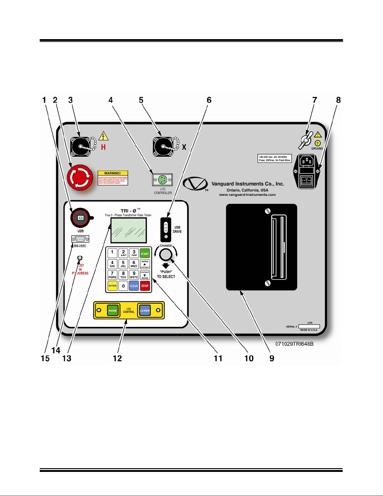
7.0 TRI-PHASE™ Front Panel Descriptions
7.1 TRI-PHASE™ Operating Controls, Indicators and Connectors
Figure 1.0 Model TRI-PHASE™ Front-Panel Controls, Indicators and Connectors
16
Page 17
TRI-PHASE OPERATING™ INSTRUCTIONS
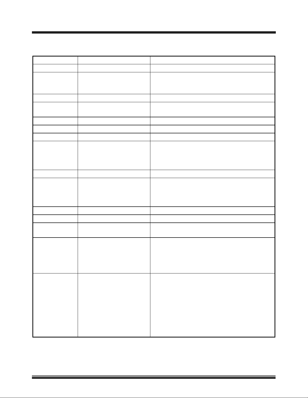
7.1
TRI-PHASE™ Operating Controls, Indicators and Connectors (continued)
Table 4.0 Model TRI-PHASE™ Front-Panel Controls, Indicators, and Connectors
Fig. 2.0 Index Panel Markings Functional Description
1
2
USB
EMERGENCY
USB interface port to PC
Emergency turn off test voltage switch
TURN OFF
“PUSH”
3
4
H
LTC
H voltage test connector
Load Tap Changer controller connector
CONTROLER
5
6
7
8
X
USB DRIVE
None (wing nut)
120-240Vac, 2 A,
50/ 60Hz
X voltage test connector
USB FLASH memory thumb drive interface port
Ground stud connected to substation ground
Input power connector and fused power switch
with third-wire safety ground
Fuse: 250Vac, 5 A,
Fast Blow
9
10
None (printer)
CHANGE
“PUSH”
TO SELECT
Thermal printer, 4.5-inch wide printout
Control Knob: Turning this Control Knob
scrolls through different menu options (shown
on LCD). Select the displayed menu option by
pushing the knob.
11
12
13
None (keypad)
LTC CONTROL
None (LCD display)
pushbutton operating controls, 16-keys
Load Tap Changer Control push button switches
LCD display 64 by 128 dot graphic, back-
lighted, sunlight readable display
14
TEST IN PROGRESS
This red LED flashes in response to a command
or when a test voltage is applied to the test
transformer. The red LED flashes with a
corresponding beeping sound at a 1 second rate
during test.
15
RS-232C
RS-232C connector for interface to an IBM
compatible computer. A 9-pin, female DB type
connector. Data rate is set to 115,000 baud, 1
start bit, 8 data bits, 2 stop bits, and no parity bit.
Connector pin functions are:
PIN SIGNAL
2 Rx
3 Tx
5 Gnd
17
Page 18

TRI-PHASE OPERATING™ INSTRUCTIONS
8.0 TRI-PHASE™ Printer and Printer Paper
The TRI-PHASE™ built-in thermal printer uses 4.5-inch wide thermal paper for printing test
results. In order to maintain the highest quality printing and to avoid paper jams we recommend
using the paper supplied by our factory. Paper can be ordered from the following sources.
Vanguard Instruments Co, Inc.
1520 S. Hellman Ave.
Ontario, CA 91761
Tel: 909-923-9390
Fax: 909-923-9391
Part Number: TP-4 Paper
OR
BG Instrument Co.
13607 E. Trent Ave.
Spokane, WA 99216
Tel: 888-244-4004
Fax: 509-893-9803
Part Number: TP4 paper
9.0 Memory Storage Capabilities
9.1 Test Record Memory Storage Capabilities
The TRI-PHASE™ is capable of storing up to 112 transformer test records in the on-board FLASH
EEPROM. The TRI-PHASE™ is capable of restoring test records from the on-board FLASH
EEPROM. After a test record is restored it may be viewed on the TRI-PHASE™ LCD screen
and/or transferred to a USB FLASH memory thumb drive, to a PC, or printed using the built-in
thermal printer. Storing more than 112 transformer test records requires a USB FLASH memory
thumb drive. A USB FLASH thumb drive is capable of storing 999 transformer test records.
9.2 Transformer Test Plan Memory Storage Capabilities
Each TRI-PHASE™ is capable of storing up to 128 Transformer Test Plans in the FLASH
EEPROM. Test plans allow the operator to perform a complete transformer test and obtain
PASS/FAIL results.
10.0 Operating Voltages
10.1 Operating Voltages
The TRI-PHASE™ operating voltage is 100-240Vac, 50/60Hz.
The TRI-PHASE™ has built-in ground fault isolation detection and will only operate with
operating voltages that are ground-fault isolated.
18
Page 19

TRI-PHASE OPERATING™ INSTRUCTIONS
11.0 Special Features
11.1 LCD Contrast Control
To darken the LCD display, press and hold the “V Contrast” switch for more than two seconds. To
lighten the LCD display, press and hold the “W Contrast” switch for more than two seconds.
11.2 Test Voltages
The TRI-PHASE™ has three selectable test voltages: 8Vac, 40Vac, and 100Vac. The TRIPHASE™ has two selectable test frequencies, 50 Hz and 60 Hz. Refer to Table
19.0 for test voltage
selection.
11.3 Computer Control And TTRA Software Application
The TRI-PHASE™ may be controlled by an IBM compatible PC via the RS-232 interface port or
USB interface port. Cables for the RS-232C and USB connections are supplied with each TRIPHASE™. The operator connects the appropriate PC interface cable to the TRI-PHASE™. A
Microsoft Windows
™
Based PC TTRA software application is delivered with each TRI-PHASE™.
The TRI-PHASE™ test result data is stored in ASCII format making it possible to export the data
into any database desired. Microsoft Windows XP™, and Microsoft Windows Vista™ support the
TTRA software application. Using this software application, the operator has the ability to:
• Perform transformer test(s) under control of the PC
• Save transformer test results directly to the PC
• Transfer test records stored in the TRI-PHASE™ FLASH EEPROM to the PC
• Transfer transformer test plans generated by the TTRA to the TRI-PHASE™ FLASH
EEPROM memory
• Transfer test records from the TRI-PHASE™ FLASH EEPROM to the thumb drive
• Transfer test plans generated by the TTRA into the thumb drive
11.4 USB FLASH Memory Thumb Drive
The USB FLASH memory thumb drive is capable of storing test records and test plans. This device
will be referred to from now on as the “thumb drive”. Many of the operational menus described in
this manual will contain an extra option to select the thumb drive. When this option is selected, the
submenus will allow for selection of the internal FLASH EEPROM memory or the thumb drive
FLASH memory. Refer to section
25.0 for further details of the menus which have this option.
19
Page 20
TRI-PHASE OPERATING™ INSTRUCTIONS
12.0 Typical Cable Hook Up Configurations
Always ground the TRI-PHASE™ with the provided ground cable contained in the cable set
before connecting H and X cables. Ground the transformer bushings before connecting test leads to
transformer. This procedure prevents inducing any voltages into the TRI-PHASE™. All transformer
buss connections must be removed and transformer isolated before performing testing of
transformer. Typical TRI-PHASE™ cable connections to different transformers are illustrated in
Figure 2.0 to Figure 13.0.
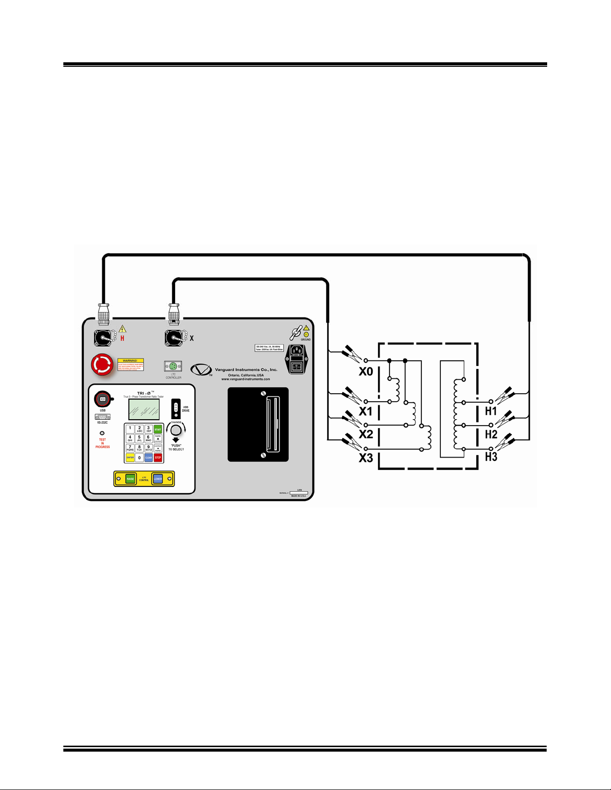
12.1 Typical Cable Connections to a Delta-Wye Transformer
Typical cable connections to a Delta to Wye transformer are shown in
Figure 2.0 and Figure 4.0.
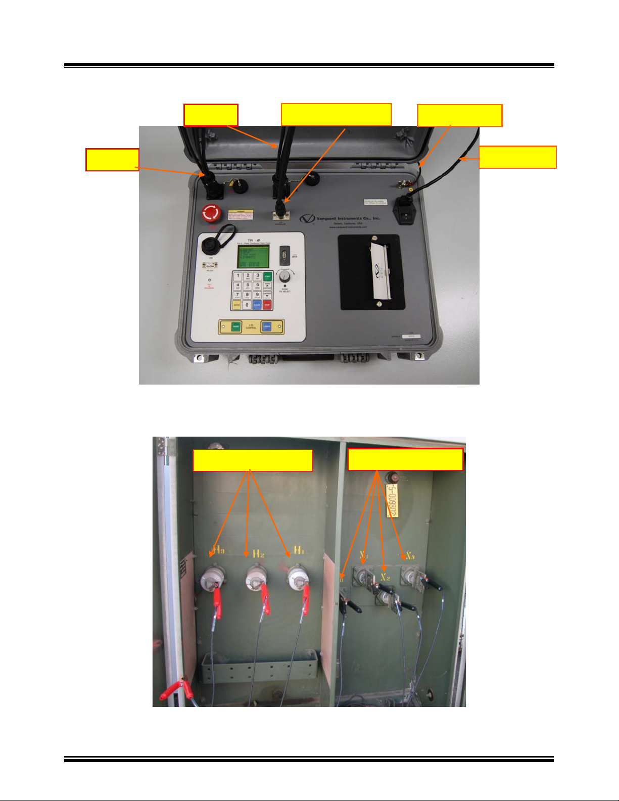
Figure 2.0 Typical H & X Cable Connections to a Delta-Wye Transformer
20
Page 21
TRI-PHASE OPERATING™ INSTRUCTIONS
12.2 Typical Cable Connections to a Delta-Wye Transformer (continued)
X Cable
LTC Control Cable
Gnd Cable
H Cable
Power Cable
Figure 3.0 Typical Front Panel Cable Connectors
H Cable Connections
X Cable Connections
Figure 4.0 Typical H & X Cable Connections to Delta-Wye Transformer
21
Page 22
TRI-PHASE OPERATING™ INSTRUCTIONS
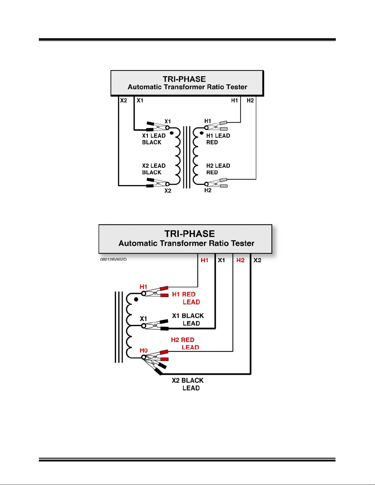
12.3 Single Phase Transformer Typical Connections
Figure 5.0 Single Phase Transformer Typical Connections
Figure 6.0 Single Phase Auto Transformer Typical Connections
22
Page 23
TRI-PHASE OPERATING™ INSTRUCTIONS
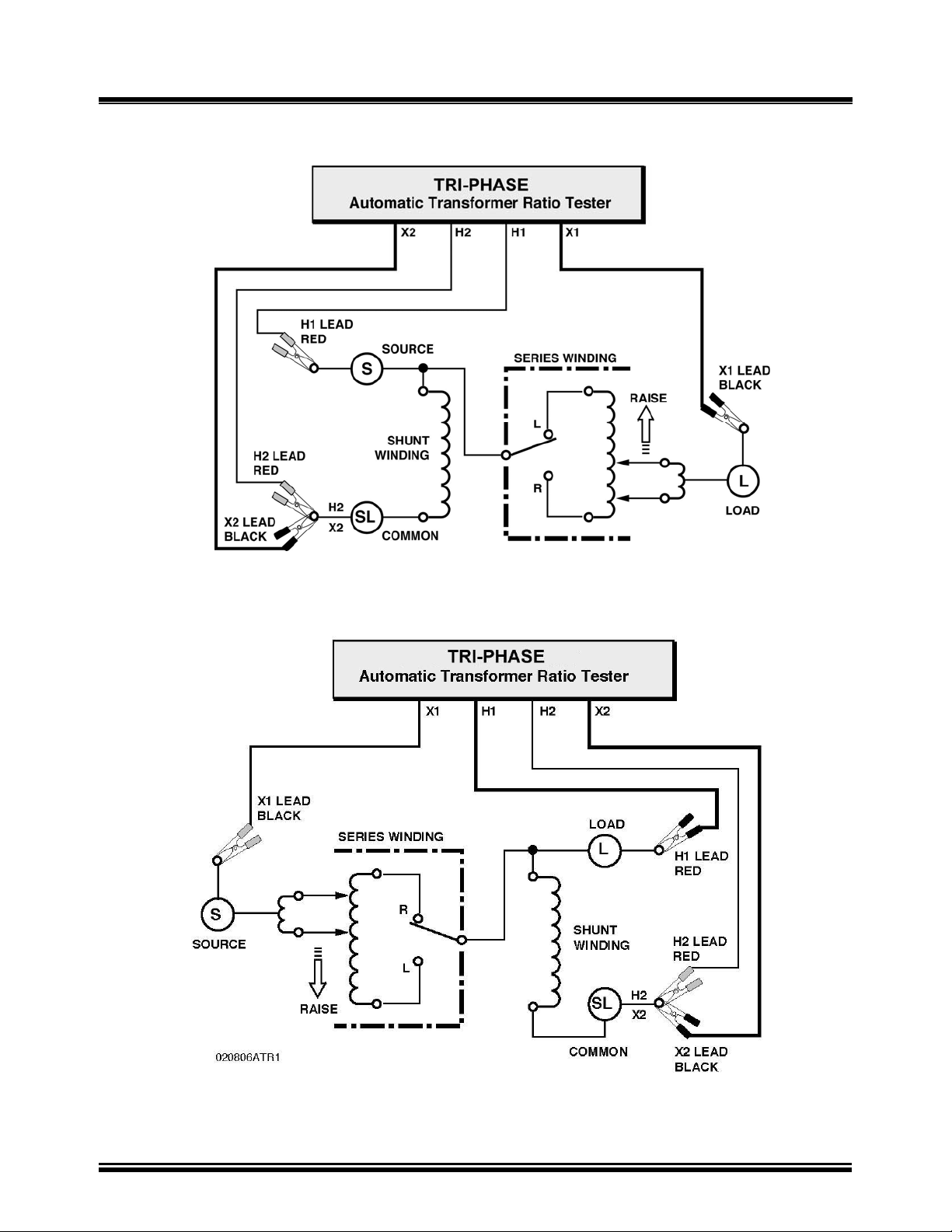
12.4 Voltage Regulator Typical Connections
Figure 7.0 Type A Voltage Regulator Typical Connections
Figure 8.0 Type B Voltage Regulator Typical Connections
23
Page 24
TRI-PHASE OPERATING™ INSTRUCTIONS
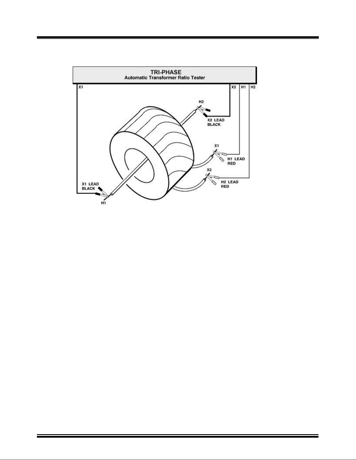
12.5 Donut Type (un-mounted) Current Transformer (CT) Typical Connections
Figure 9.0 Donut Type (un-mounted) Current Transformer (CT)
Typical Connections
NOTE:
H and X test leads are reversed for the CT ratio test shown above.
24
Page 25
12.6 Multi-tap CT Typical Connections
TRI-PHASE OPERATING™ INSTRUCTIONS
Figure 10.0 Multi-tap CT Typical Connections
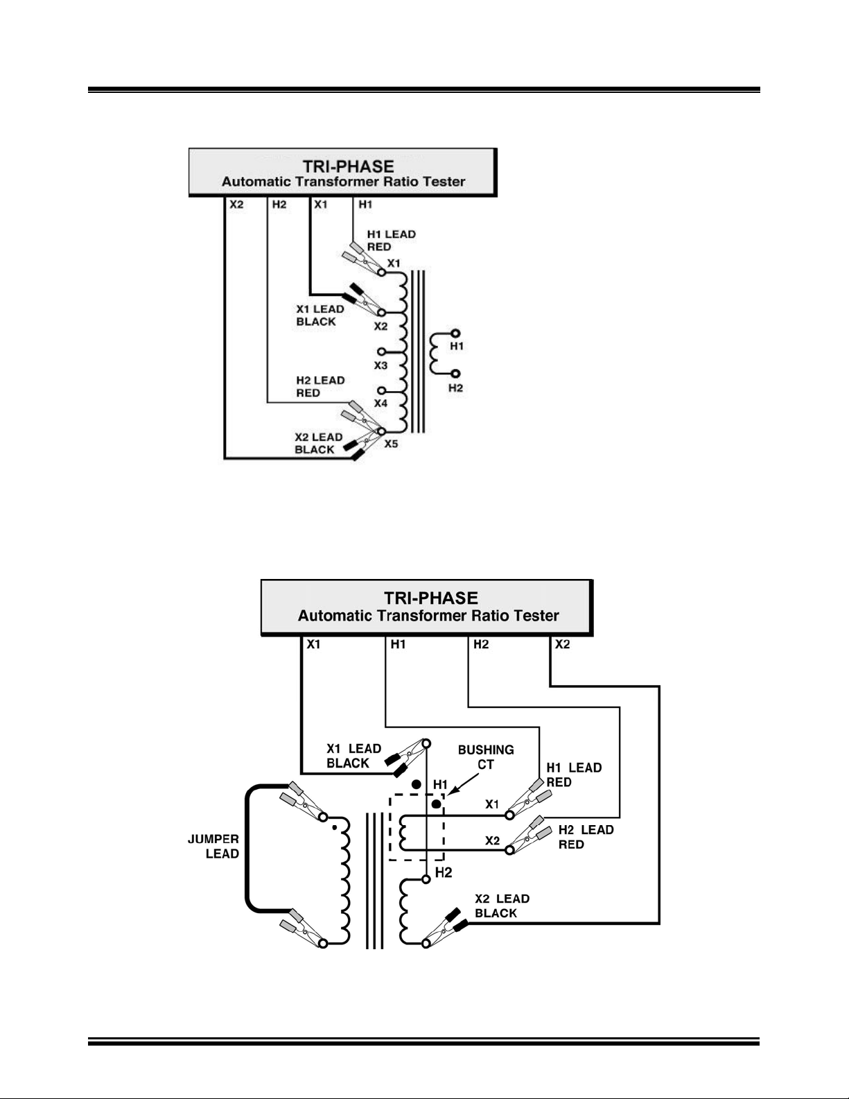
12.7 Bushing-Mount-CT on A Typical Single Phase Transformer Connections
Figure 11.0 Bushing-Mount-CT on A Typical Single Phase Transformer Connections
25
Page 26
TRI-PHASE OPERATING™ INSTRUCTIONS
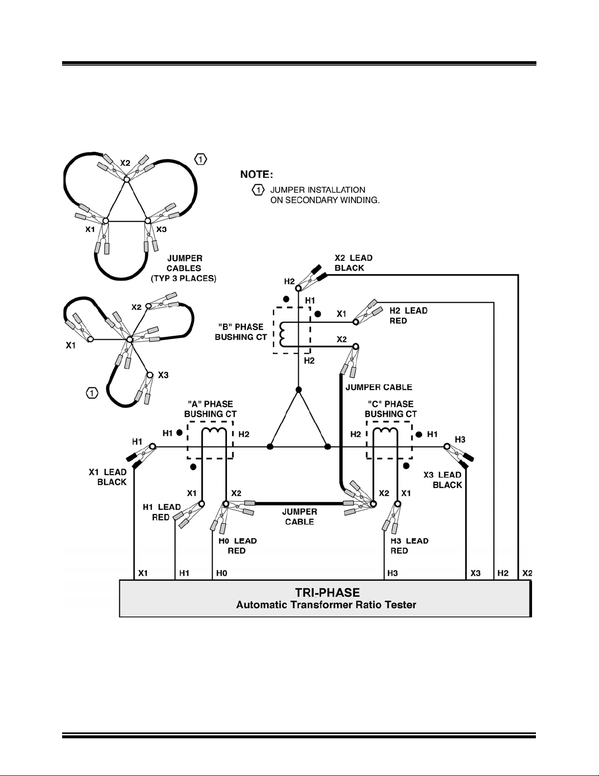
12.8 Bushing Mount CT’s on Typical Delta Transformer Connections
NOTE:
Install jumper on the unused winding
Figure 12.0 Bushing Mount CT’s on Typical Delta Transformer Connections
NOTE:
The CT turns-ratio is obtained by performing a YNd test.
Install jumpers on transformer secondary windings
26
.
Page 27
TRI-PHASE OPERATING™ INSTRUCTIONS
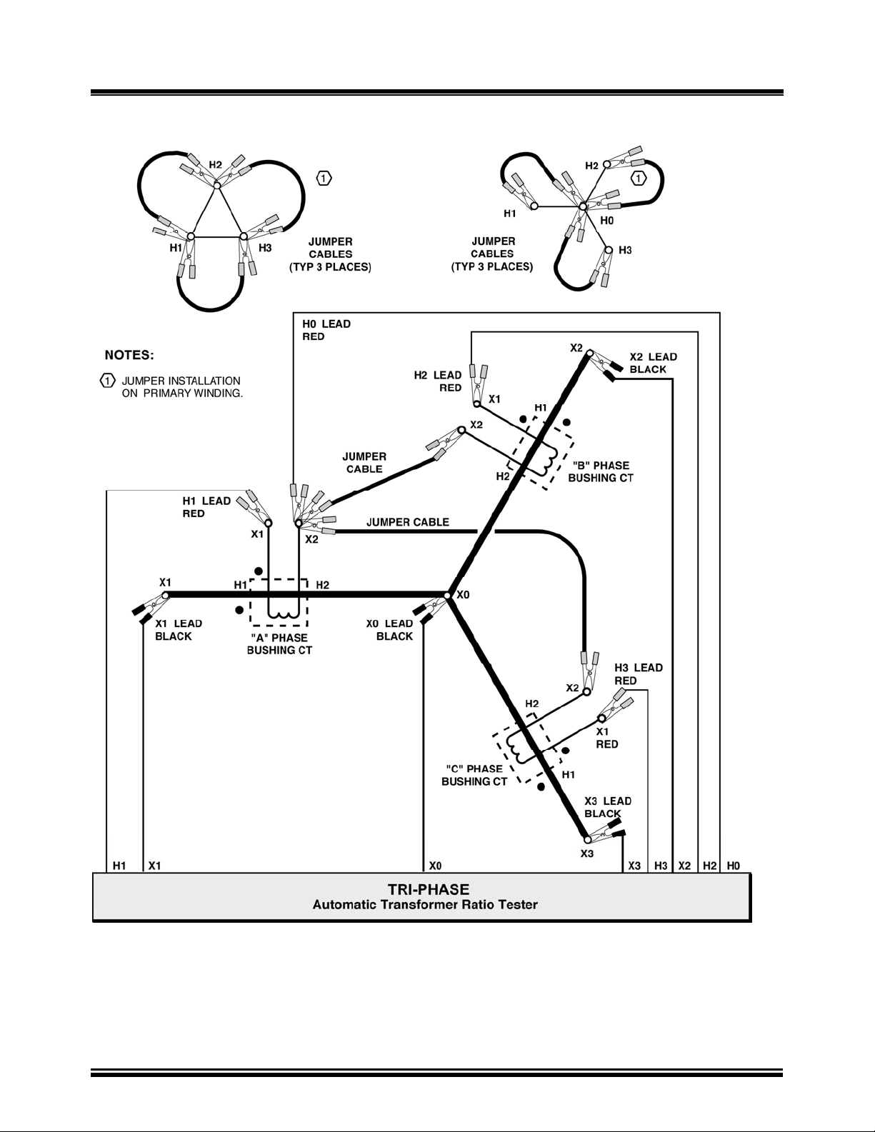
12.9 Bushing Mount CT’s on Typical Wye Transformer Connection
Figure 13.0 Bushing Mount CT’s on Typical Wye Transformer Connection
NOTE:
The CT turns-ratio is obtained by performing an YNyn test.
Install jumpers on transformer primary windings.
27
Page 28

TRI-PHASE OPERATING™ INSTRUCTIONS
13.0 Single-Phase Transformer Test Procedure
Table 7.0 shows the procedure to test a single-phase transformer (2,400 V/240 V). Detailed
descriptions of each menu are provided in the following sub-sections. Refer to Figure 1.0 for
location of controls. The precondition for the following test procedure is that no previous singlephase transformer test has been performed (i.e., no stored test results in non-volatile memory), and
there were no previous test records restored to non-volatile memory.
NOTE:
Pressing the “STOP” button aborts all tests and/or submenus
and returns the LCD screen display to the “Main Menu”.
Table 5.0 Single-Phase Transformer Test Procedure
STEP DESCRIPTION DISPLAY ACTION
1 Select “Run Test” from the
“Main Menu”
2 Select “Single Phase” from
“Transformer Configuration
Menu”
3 “Transformer Name Plate
Voltage Status Display”
Select “YES”
4 “Name Plate Voltage Status
Display”
Enter H line voltage from
transformer nameplate
5 “Name Plate Voltage Status
Display”
Confirm H voltage
6 “Name Plate Voltage Status
Display”
Enter X line voltage from
transformer nameplate
7 “Name Plate Voltage Status
Display”
Confirm X voltage
1.RUN TEST
2.SETUP
3.TEST PLAN
4.DIAGNOSTIC
TIME: 20:15:00
DATE: 07/16/08
XFMR CONFIG:
1.SINGLE PHASE
2.Dy
3.Yd
4.Dd
5.Yy
6.Next Page
XFMR NAME PLATE VLTG
1.YES
2.NO
NAME PLATE VOLTAGE:
H : X
0 :
NAME PLATE VOLTAGE:
H : X
2,400 :
NAME PLATE VOLTAGE:
H : X
2,400: 0
NAME PLATE VOLTAGE:
H : X
2,400 : 240
Press key number 1
or push down Control
Knob
Press key number 1
or push down Control
Knob
Press key number 1
or push down Control
Knob
Use keys 0-9 for data
entry of transformer
name plate voltage
Press “ENTER”
or push down Control
Knob
(2400 was keyed for
this test)
Use key numbers 0-9
for data entry
Press “ENTER”
or push down Control
Knob
(240 was keyed for
this test)
28
Page 29
TRI-PHASE OPERATING™ INSTRUCTIONS
13.0 Single-Phase Transformer Test Procedure (continued)
Table 5.0 Single-Phase Transformer Test Procedure (continued)
STEP DESCRIPTION DISPLAY ACTION
8 “Start/Stop Test Status Display”
9 “Test in Progress” status display
10 “Test Results Status Display”
Observe ratio, excitation current,
and percentage error on LCD
display
11 “Test Results Status Display”
Go to next LCD display
12 Select “YES” from the “Print
Test Results Menu” to print test
result on built-in
printer
13 Select “Column” from the “Print
Format Menu”
14 Select “YES” from the “Keep
This Reading Menu” to store
current test reading (i.e., test
results) in non-volatile memory
NOTE:
Refer to note at end of table
“START” TO TEST
OR
“STOP” TO ABORT
TEST IN PROGRESS
PLEASE WAIT…
RATIO mA %DIFF
+10.005 1.9 0.05
RATIO mA %DIFF
+10.005 1.9 0.05
PRINT TEST RESULTS?
1.YES
2.NO
PRINT FORMAT
1.COLUMN
2.DETAILED
KEEP THIS READING?
1.YES
2.NO
Press START key
None
None
Press any key or push
down Control Knob
Press key number 1
or push down Control
Knob
Press key number 1 or
push down Control
Knob for a column
report.
Press key number 1 or
push down Control
Knob to store reading
15 “Test Saved Status Display”
Current test reading is saved
16 Select “NO” from the “Run
Another Test Menu”
17 Selecting “YES” from the “Save
This Record Menu”
Store test results in FLASH
EEPROM
TEST SAVED
RUN ANOTHER TEST?
1.YES
2.NO
3. REPEAT PREV. TEST
SAVE THIS RECORD?
1.YES
2.NO
29
Press any key or push
down Control Knob
Press key number 2
Selection of 2 may be
made by turning the
Control Knob. Push
down Control Knob
after 2 is selected
Press key number 1
or push down Control
Knob
Page 30
TRI-PHASE OPERATING™ INSTRUCTIONS
13.0 Single-Phase Transformer Test Procedure (continued)
Table 5.0 Single-Phase Transformer Test Procedure (continued)
STEP DESCRIPTION DISPLAY ACTION
18 “Record Saved” confirmation
status display
Test results saved in FLASH
EEPROM as a test record
NOTE:
The next sequential record
number (#) is automatically
generated and displayed
19 Return to “Main Menu”
RECORD NUMBER #
HAS BEEN SAVED
1.RUN TEST
2.SETUP
3.TEST PLAN
4.DIAGNOSTIC
TIME: 20:15:00
DATE: 07/16/08
Press any Key or push
down Control Knob
None
NOTE:
The precondition for the above test procedure was that no previous single-phase transformer test
record was residing in temporary memory. Once a single phase test record has been saved to
FLASH EEPROM, or a single phase test record restored from FLASH EEPROM and another single
phase transformer test is performed, selecting “YES” in response to “Keep This Reading” at step
17 results by displaying the following menu.
PREVIOUS DATA IN BUF.
1.APPEND PREV. DATA
2.CLEAR PREV. DATA
Selecting menu option 1 (“Append Prev. Data”) will result in appending the current test results to
all of the previous test results from the test record stored in temporary memory, assigning this new
record to the next test record number in sequence. Selecting menu option 2, “Clear Prev. Data” will
result in clearing the temporary memory of all previous test results from the test record except the
current test results and assigning this test result to the next sequential test record number. The
temporary memory will be lost when the TRI-PHASE™ is powered-off, but the test records remain
in the TRI-PHASE™ FLASH EEPROM non-volatile internal memory.
30
Page 31

TRI-PHASE OPERATING™ INSTRUCTIONS
13.1 Main Menu
1.RUN TEST
2.SETUP
3.TEST PLAN
4.DIAGNOSTIC
TIME: 20:15:05
DATE: 07/16/08
Figure 14.0 Main Menu
a. Description: The “Main Menu” (i.e., “start-up”) provides selection of the primary
functions of the TRI-PHASE™. These functions consist of one or more sub-menus that
allow the operator to test a transformer, select various settings or options, select test plan
options, or perform diagnostics on the TRI-PHASE™.
b. Origin: The “Main Menu” displays on the LCD after power is applied to the TRI-
PHASE™.
c. Action Options:
Press key number 1 to select “Run Test”
Press key number 2 to select “Setup”
Press key number 3 to select “Test Plan Menu”
Press key number 4 to select “Diagnostic”
Selection may also be made by turning the Control Knob to select a menu option and then
pushing down on the Control Knob once the selection is made.
d. Action To Perform: Select menu option 1 for this example.
NOTES:
Real time and date is displayed at the bottom of LCD screen.
Refer to section
To return to the “Main Menu” at any time press “STOP” on the keypad.
11.1 for LCD contrast control operation.
31
Page 32

TRI-PHASE OPERATING™ INSTRUCTIONS
13.2 Transformer Configuration Selection Menu
XFMR CONFIG:
1.SINGLE PHASE
2.Dy
3.Yd
4.Dd
5.Yy
6.Next Page
Figure 15.0 Transformer Configuration Selection First Menu
XFMR CONFIG:
1.Dz
2.Zd
3.Yz
4.Zy
5.TT
6.Previous Page
Figure 16.0 Transformer Configuration Selection Second Menu
a. Description: Either “Transformer Configuration Selection Menu” above will allow the
operator to select the transformer type to be tested. There are two menus for this selection.
The first menu is shown in Figure 15.0 which is displayed first. When the operator selects
“Next Page” from the first menu, the second menu is displayed as shown in Figure 16.0.
b. Origin: The “Transformer Configuration Selection” first menu displays after selecting
“Run Test” from the “Main Menu” (Figure 14.0).
c. Action Options: Select the type of transformer configuration to be tested by pressing key
numbers that correspond to the numbered menu items on the keypad, or by turning the
Control Knob to the desired menu item, then pushing down on the Control Knob once
selected.
d. Action To Perform: With the first menu displayed, select the menu option 1 for this
example.
NOTE:
The TRI-PHASE™ will support 130 transformer types defined by ASNCI/CEI/ICE standards.
All transformer configurations supported by the TRI-PHASE™ are listed in Appendix B.
32
Page 33

TRI-PHASE OPERATING™ INSTRUCTIONS
13.3 Transformer Name Plate Voltage Menu
XFMR NAME PLATE VLTG
1.YES
2.NO
Figure 17.0 Transformer Nameplate Voltage Menu
a. Description: This menu provides access to the “Name Plate Voltage” status display
(Figure 18.0) for entry of the transformer nameplate voltages which are used to derive a
calculated turns-ratio. The calculated turns-ratio is then used to compare the measured
turns-ratio and calculate a percentage error reading.
b. Origin: The transformer nameplate voltage menu displays after selecting “Single Phase”
from options listed in the “Transformer Configuration Selection Menu” (Figure 15.0). For
other transformer configurations, this menu displays prior to the “Start/Stop Test” status
display.
c. Action Options: Press key number 1 (“YES”) push down the Control Knob to use the
calculated turns-ratio in the test results and advance to the “Name Plate Voltage” status
display (Figure 18.0). Press key number 2 to bypass this option and advance to the
“Start/Stop Test” status display (Figure 22.0). Selection may also be made by turning the
Control Knob to select a menu option, then pushing down on the Control Knob once the
selection is made.
d. Action To Perform: Select menu option 1 for this example.
33
Page 34

TRI-PHASE OPERATING™ INSTRUCTIONS
13.4 Transformer Voltage Data Entry Status Displays
NAME PLATE VOLTAGE:
H : X
0 :
Figure 18.0 Name Plate Voltage Status Display
NAME PLATE VOLTAGE:
H : X
2,400 :
Figure 19.0 Name Plate Voltage Display, H Voltage Keyed In
NAME PLATE VOLTAGE:
H : X
2,400 : 0
Figure 20.0 Name Plate Voltage Display, H Voltage Entered
NAME PLATE VOLTAGE:
H : X
2,400 : 240
Figure 21.0 Name Plate Voltage Display, X Voltage Keyed In
a. Description: Allows for entry of the H and X voltages for the transformer to be tested,
which are used to calculate the turns-ratio. The operator enters the transformer nameplate
voltages.
b. Origin: The name plate voltage status will display on LCD after the operator has selected
menu option 1 on the “Transformer Name Plate Voltage Menu” (Figure 17.0).
c. Action Options: Press key numbers 0 thru 9 to enter transformer voltages. Press the
“ENTER” key to confirm voltage entry. The Control Knob may be pushed down after the
numeric keys are pressed for each entry of H and X voltages. Press the “CLEAR” key to reenter data.
d. Action To Perform: Enter name plate voltages of 2400 for H, and enter 240 for X for this
test example.
34
Page 35

TRI-PHASE OPERATING™ INSTRUCTIONS
13.5 Start/Stop Test Status Display
“START” TO TEST
OR
“STOP” TO ABORT
Figure 22.0 Start/Stop Test Status Display
a. Description: Allows the operator to star t to test or abort a test.
b. Origin: The LCD displays “Start/Stop Test Status Display” after the operator enters the
nameplate voltage for X (Figure 21.0) or selects 2 on the “Transformer Name Plate Voltage
Menu” (Figure 17.0).
c. Action Options: Press the “START” key to start a test and advance to the “Test In
Progress Status Display” (Figure 23.0). Press the “STOP” key to abort a test and return to
the “Main Menu”.
d. Action To Perform: Press the “START” key to start the test for this example.
35
Page 36

TRI-PHASE OPERATING™ INSTRUCTIONS
13.6 Test In Progress Status Display
TEST IN PROGRESS
PLEASE WAIT…
Figure 23.0 Test In Progress Status Display
a. Description: The “Test In Progress Status Display” (Figure 23.0) is displayed when the
turns-ratio test is performed.
b. Origin: The LCD displays the “Test In Progress Status Display” after the operator presses
the “START” key (Figure 22.0).
c. Action Options: None.
d. Action To Perform: Observe status.
36
Page 37

TRI-PHASE OPERATING™ INSTRUCTIONS
13.7 Test Results Status Display
RATIO mA %DIFF
+10.005 1.9 0.05
Figure 24.0 Test Results Status Display
a. Description: Displays the transformer winding polarity, turns-ratio, excitation current (in
milliamps), and turns-ratio percentage error after completion of the transformer test. A
typical turns-ratio test result screen is shown in Figure 24.0. The display result is explained
below:
Ratio displayed: 10.005
Polarity displayed: “+” (in phase)
Excitation current: 1.9mA
Percentage error: 0.05%
b. Origin: The LCD displays “Test Results Status Display” (Figure 24.0) after the “Test In
Progress Status Display” (Figure 23.0).
c. Action Options: Press any key or push down the Control Knob to go to the “Print Test
Results Menu” (Figure 25.0).
d. Action To Perform: Observe the test result status, then press any key or push down the
Control Knob.
NOTE:
“% DIFF” is calculated as the Absolute Value of [(Cal ratio –Measured ratio)/Cal ratio] x 100.
“% DIFF” will only be displayed if nameplate voltages were entered.
37
Page 38

TRI-PHASE OPERATING™ INSTRUCTIONS
13.8 Print Test Results Menu
PRINT TEST RESULTS?
1.YES
2.NO
Figure 25.0 Print Test Results Menu
a. Description: The TRI-PHASE™ has the capability to p rint the current test results
(displayed on the LCD screen) using the built-in thermal printer.
b. Origin: The “Print Test Results Menu” is displayed after operator presses any key or
pushes down on the Control Knob from the “Test Result Status Display” (Figure 24.0).
c. Action Options: Press key number 1 (“YES”) or push down the Control Knob to advance
to the “Print Format Menu” (Figure 26.0). Press key number 2 to advance to “Keep This
Reading Menu” (Figure 29.0). Number 2 may be selected by turning the Control Knob,
then pushing down on the Control Knob after 2 is selected.
d. Action To Perform: Select menu option 1 for this example.
13.9 Print Format Menu
PRINT FORMAT?
1.COLUMN
2.DETAILED
Figure 26.0 Print Format Menu
a. Description: Allows the operator to select which format to use for printing the test results.
Refer to Figure 27.0 for a typical column format printout. Refer to Figure 28.0 for a
detailed format printout.
b. Origin: This menu is displayed after the operator selects 1 (“YES”) from the “Print Test
Results Menu” (
c. Action Options: Press key number 1 or push down on the Control Knob to select the
column format print out of the test results. Press key number 2 to select the detail format
printout of the test results. Number 2 may be selected by turning the Control Knob, then
Figure 25.0).
38
Page 39

TRI-PHASE OPERATING™ INSTRUCTIONS
pushing down on the Control Knob after number 2 is selected.
d. Action To Perform: Select menu option 1 for this example.
e. Results of Action: Once the desired print format is selected the test results are printed and
the LCD displays the “Keep This Reading Menu” (Figure 29.0).
39
Page 40

13.10 Test Result Column Format Printout
TRI-PHASE OPERATING™ INSTRUCTIONS
1
2
3
4
5
6
7
8
12 11 10 9
Figure 27.0 Single Phase Column Format Printout
A typical single-phase transformer test results printout in column format is shown in Figure 27.0.
The test results printout is explained below.
1. Test record time and date is printed at the top of the printout
2. Test voltage is 40 volts at 60 Hz for this test. Refer to section
11.2 for more details about
test voltages and frequencies
3. Type of transformer under test is single phase
4. Transformer configuration diagram
5. H tap voltage is 2,400 volts
6. X tap voltage is 240 volts
7. Calculated turns-ratio is 10.000
8. Percentage error between calculated ratio and measured ratio is 0.05%
9. Measured winding phase angle is 0.02 degrees
10. Excitation current is 1.9mA
11. Measured ratio is 10.005
12. Winding polarity is shown as “+” or “in phase
40
Page 41

13.11 Test Result Detail Format Printout
TRI-PHASE OPERATING™ INSTRUCTIONS
1
2
3
4
5
6
7
8
9
10
11
Figure 28.0 Single Phase Detail Format Printout
41
Page 42

TRI-PHASE OPERATING™ INSTRUCTIONS
13.11 Test Result Detail Format Printout (continued)
The same report is now shown in detailed format printout (Figure 28.0).
The test results detail printout is explained below.
1. Test record time and date is printed at the top of the printout
2. Test voltage is 40 volts at 60 Hz for this test. Refer to paragraph 11.2 for more details
about test voltages and frequencies
3. Type of transformer under test is Single Phase
4. Transformer configuration diagram
5. H tap voltage is 2,400 volts
6. X tap voltage is 240 volts
7. Calculated turns-ratio is 10.000
8. Measured ratio is 10.005
9. Percentage error between calculated ratio and measured ratio is 0.05%
10. Measured winding phase angle is 0.02 degrees
11. Excitation current is 1.9mA
NOTE:
A phase angle printout of 999.9 indicates an unstable phase angle reading.
42
Page 43

TRI-PHASE OPERATING™ INSTRUCTIONS
13.12 Keep This Reading Menu
KEEP THIS READING?
1.YES
2.NO
Figure 29.0 Keep This Reading Menu
a. Description: The operator has the option to store the current test result in non-volatile
memory or disregard the current test results.
b. Origin: After the operator selects 1 (“YES”) or the operator selects 2 (“NO”) from the
“Print Test Results Menu” (Figure 25.0).
c. Action Options: Press key number 1 (“YES”) or push down the Control Knob to store
current transformer test results into non-volatile memory. Press key number 2 (“NO”) to
disregard the current test results. Number 2 may be selected by turning the Control Knob,
then pushing down on Control Knob after 2 is selected.
d. Action To Perform: Select menu option 1 for this example.
e. Results of Action: After selecting menu option 1, the status “TEST SAVED” is displayed
on the LCD. Press any key or push down Control Knob to go to the “Run Another Test
Menu” (Figure 31.0).
43
Page 44

TRI-PHASE OPERATING™ INSTRUCTIONS
13.13 Previous Data In Buf. Menu
PREVIOUS DATA IN BUF.
1. APPEND PREV. DATA
2. CLEAR PREV. DATA
Figure 30.0 Previous Data In Buf Menu
a. Description: This menu is displayed when there is an existing test result in memory of the
same type of transformer which is under test.
The “Append Previous Data” feature allows the operator to stop the testing in order to
perform other duties. The operator will be able to continue testing the transformer at a later
time without having to repeat any of the previous tests. It is important to remember that this
may only be accomplished when all tests are performed on the same transformer. Figure
30.0 will display when another test is performed on an identical transformer configuration
and there is a test record residing in temporary memory (i.e., buf) from an identical
transformer configuration. The previous test record may be a restored test record or the
current test record for an identical transformer configuration.
For example, a previous single phase transformer configuration test record with one or
more test results from a single phase transformer configuration is stored in TRI-PHASE™
FLASH memory. These test results are also still residing in temporary memory. The
operator performs another single phase transformer configuration test. The operator selects
“YES” in response to “Keep This Reading” at step 14 of Table 5.0 resulting in saving the
test results to temporary memory and the display of Figure 30.0.
Selecting menu option 1 (“Append Prev. Data”) will result in appending the current test
result to all of the previous test results from the test record stored in temporary memory;
assigning this new record to the next test record number in sequence.
Selecting menu option 2 (“Clear Prev. Data”) will result in clearing the temporary memory
of all previous test results from the test record except the current test result and assign the
current test result to the next sequential test record number.
b. Origin: This menu displays after the operator selects 1 (“YES”) from the “Keep This
Reading Menu” (Figure 29.0)
c. Action Options: Press key number 1 to append. Press key number 2 to clear the previous
test results from temporary memory and store the current test results in FLASH EEPROM.
d. Action To Perform: Selecting option 1 or 2. After the selection is made the status “TEST
SAVED” is displayed. Press any key or push down the Control Knob to advance to the
“Run Another Test Menu” (
Figure 31.0).
44
Page 45

TRI-PHASE OPERATING™ INSTRUCTIONS
13.14 Run Another Test Menu
RUN ANOTHER TEST?
1.YES
2. NO
3. REPEAT PREV. TEST
Figure 31.0 Run Another Test Menu
a. Description: Allows the selection of performing another test on the transformer, ending
testing, or repeating the previous test.
b. Origin: After the “Test Saved Status Display”. Refer to “Keep This Reading” section
13.12.d.
c. Action Options: Press key number 1 (“YES”) or push down the Control Knob. Press key
number 2 to end the current test and advance to the “Save This Record Menu” (Figure
32.0). Selection of 2 may be made by turning the Control Knob. Push down the Control
Knob after 2 is selected.
d. Action To Perform: Select menu option 2 for this example.
45
Page 46

TRI-PHASE OPERATING™ INSTRUCTIONS
13.15 Save This Record Menu
SAVE THIS RECORD?
1.YES
2.NO
Figure 32.0 Save This Record Menu
a. Description: Allows for the transfer of current test results from the non-volatile memory
into FLASH EEPROM. Up to 112 test-records may be stored in FLASH EEPROM.
b. Origin: After selecting key 2 from the “Run Another Test Menu” (Figure 31.0).
c. Action Options: Press key number 1 (“YES”) or push down the Control Knob to save the
current test results to a test record. Press key number 2 to disregard the current test results
and advance to the “Test Record Not Saved Menu” (Figure 35.0 Test Record Not Saved
Menu). Selection of number 2 may be made by turning the Control Knob. Push down the
Control Knob after number 2 is selected.
d. Action To Perform: Select menu option 1 for this example.
46
Page 47

TRI-PHASE OPERATING™ INSTRUCTIONS
13.16 Record Saved Confirmation Status
RECORD NUMBER #
HAS BEEN SAVED!
Figure 33.0 Record Saved Confirmation Status Display
a. Description: The current test results are saved into the next sequential test record number
(#) assigned. The test record is saved in FLASH EEPROM.
b. Origin: Select menu option 1 (“YES”) from the “Save This Record Menu” (Figure 32.0).
c. Action Options: Press any key or push down the Control Knob to return to the “Main
Menu” (Figure 14.0).
d. Action To Perform: Press any key or push down the Control Knob for this example.
47
Page 48

TRI-PHASE OPERATING™ INSTRUCTIONS
13.17 Transformer Name Plate Voltage Menu For Another Test
XFMR NAME PLATE VLTG
1.YES
2.NO
3.USE PREVIOUS DATA
Figure 34.0 Nameplate Voltage Selection Menu For Another Test
a. Description: This menu displays when another test is performed. The operator has an
added option to use the same nameplate voltage data from the previous test.
b. Origin: After selecting number 1 (“YES”) from the options listed in “Run Another Test
Menu” (Figure 31.0) the “Transformer Name Plate Voltage Menu” to perform another test
displays.
c. Action Options: Press key number 1 (“YES”) or push down on the Control Knob and
advance to the “Name Plate Voltage” display (Figure 18.0). Press key number 2 to bypass
this option and advance to the “Start/Stop Test Menu” (Figure 22.0). Press key number 3 to
use the same transformer nameplate voltage data from the previous test and advance to the
“Start/Stop Test Menu”. Selection of menu items may also be made by turning the Control
Knob to select a menu option, then pushing down on the Control Knob once the selection is
made.
48
Page 49

TRI-PHASE OPERATING™ INSTRUCTIONS
13.18 Test Record Not Saved Menu
ARE YOU SURE?
DATA WILL BE LOST!
1.DO NOT SAVE RECORD
2.SAVE RECORD
Figure 35.0 Test Record Not Saved Menu
a. Description: This menu displays after the operator decides to not save the test results to a
test record.
b. Origin: Press key number 2 (“NO”) from the “Save This Record Menu” (Figure 32.0).
c. Action Options: Press key number 1 or push down the Control Knob to select not to save
the test results to a test record. Press key number 2 to save test results to a test record.
Selection of number 2 may be made by turning the Control Knob. Push down the Control
Knob after number 2 is selected.
49
Page 50

TRI-PHASE OPERATING™ INSTRUCTIONS
14.0 Dyn1 Transformer Test Procedure
Table 6.0 shows the procedure to test a Dyn1 (12,000 V/208 V) transformer.
Table 6.0 Dyn1 Transformer Test Procedure
STEP DESCRIPTION DISPLAY ACTION
1 Select “Run Test” from
“Main Menu”
2 Select “Dy” (Delta to Wye)
from the “Transformer
Configuration” first menu
3 Select “YES” from the “X0
Accessible Menu”
X0 (neutral)
4 “Transformer Name Plate
Voltage” status display
Select “YES”
5 “Name Plate Voltage” status
display
Enter H line voltage from
transformer nameplate
1.RUN TEST .
2.SETUP
3.TEST PLAN
4.DIAGNOSTIC
TIME: 20:15:00
DATE: 07/16/08
XFMR CONFIG:
1. SINGLE PHASE
2. Dy .
3.Yd
4.Dd
5.Yy
6.Next Page
X0 ACCESSIBLE?
1.YES .
2.NO
NAME PLATE VOLTAGE
1.YES .
2.NO
NAME PLATE VOLTAGE:
H : X
0 :
Press key number 1
or push down
Control Knob
Press key number 2
or push down
Control Knob
Press key number 1
or push down
Control Knob
Press key number 1
or push down
Control Knob
Use keys 0-9 for
data entry of
transformer name
plate voltage
6 “Name Plate Voltage” status
display
Confirm H voltage
7 “Name Plate Voltage” status
display. Enter X line voltage
from transformer nameplate
8 “Name Plate Voltage Status
Display”
Confirm X voltage
9 “Start/Stop Test Status
Display”
NAME PLATE VOLTAGE:
H : X
12,000 :
NAME PLATE VOLTAGE:
H : X
12,000 : 0
NAME PLATE VOLTAGE:
H : X
12,000 : 208
“START” TO TEST
OR
“STOP” TO ABORT
50
Press “ENTER”
or push down
Control Knob
(12000 was keyed
for this test)
Use key numbers 0
through 9 for data
entry
Press “ENTER” or
push down Control
Knob
(208 was keyed)
Press START key
Page 51

TRI-PHASE OPERATING™ INSTRUCTIONS
14.0 Dyn1 Transformer Test Procedure (continued) Table 6.0 Dyn1 Transformer Test Procedure (continued)
STEP DESCRIPTION DISPLAY ACTION
10 “Test in Progress Status
Display”
11 “Test Results Status Display”
Observe ratio, excitation
current, and percentage error
on LCD display
12 “Test Results Status Display”
Observe ratio, excitation
current, and percentage error
on LCD display
13 “Test Results Status Display”
Observe ratio, excitation
current, and percentage error
on LCD display
14 “Test Results Status Display”
Go to next LCD display
TEST IN PROGRESS
PLEASE WAIT…
RATIO mA %DIFF
A 57.757 2.3 0.11
B 57.754 2.4 0.11
C 57.741 3.4 0.08
XFMR TYPE: Dyn1
PHASE DATA
Phs A Phs B Phs C
30.01 150.00 270.01
SINGLE PHASE TEST RSLT:
RATIO mA %DIFF
A +100.06 2.4 0.14
B +100.02 1.9 0.09
C +100.02 2.6 0.00
XFMR TYPE: Dyn1
SINGLE PHASE TEST RSLT:
RATIO mA %DIFF
A +100.06 2.4 0.14
B +100.02 1.9 0.09
C +100.02 2.6 0.09
XFMR TYPE: Dyn1
None
None Three-phase
test turns-ratio results
are shown first.
None Three-phase
phase angle test
results are briefly
shown next.
None
Single-phase test
results are displayed
last
Observe test results
Press any key or push
down Control Knob
15 Select “YES” from the “Print
Test Results Menu” to print
test result on built-in printer
16 “Print Format Menu”
Select either print format
17 Select “YES” from the “Keep
This Reading Menu” to store
current test reading in nonvolatile memory
NOTE:
Refer to note at end of table
18 “Test Saved Status Display”
Current test reading is saved
PRINT TEST RESULTS?
1.YES .
2.NO
PRINT FORMAT
1.COLUMN .
2.DETAILED
KEEP THIS READING?
1.YES .
2.NO
TEST SAVED
51
Press key number 1
or push down
Control Knob
Press key number 1
or key number 2.
Selection of 1 or 2
may be made by
turning the Control
Knob. Push down
Control Knob after
selection is made
Press key number 1
or push down
Control Knob
Press any key or push
down Control Knob
Page 52

TRI-PHASE OPERATING™ INSTRUCTIONS
14.0 Dyn1 Transformer Test Procedure (continued) Table 6.0 Dyn1 Transformer Test Procedure (continued)
STEP DESCRIPTION DISPLAY ACTION
19 Select “NO” from the “Run
Another Test Menu”
20 Store test results in FLASH
EEPROM
21 “Record Saved” confirmation
status display
Test results saved in FLASH
EEPROM as a test record
NOTE:
The next sequential record
number (#) is automatically
assigned
22 Return to “Main Menu”
RUN ANOTHER TEST?
1.YES .
2.NO
3. REPEAT PREV. TEST
SAVE THIS RECORD?
1.YES .
2.NO
RECORD NUMBER #
HAS BEEN SAVED
1.RUN TEST .
2.SETUP
3.TEST PLAN
4.DIAGNOSTIC
TIME: 20:15:00
DATE: 07/16/08
Press key number 2
Selection of 2 may be
made by turning the
Control Knob. Push
down Control Knob
after 2 is selected
Press key number 1
or push down
Control Knob
Press any Key or
push down Control
Knob
None
NOTE:
The precondition for the above test procedure was that no previous single-phase transformer test
record was residing in temporary memory. Once a single phase test record has been saved to
FLASH EEPROM, or a single phase test record restored from FLASH EEPROM and another single
phase transformer test is performed, select “YES” in response to “Keep This Reading” at step 17
results in the display of the following menu.
PREVIOUS DATA IN BUF.
1.APPEND PREV. DATA .
2.CLEAR PREV. DATA
The “PREVIOUS DATA IN BUF.” menu is displayed when previous test data is stored in
temporary memory. Selecting menu option 1 (“Append Prev. Data”) will append the current test
results to the previous test data stored in temporary memory. Selecting menu option 2 (“Clear Prev.
Data”) will store only this new test data in the temporary memory (and clear the previous data). The
temporary memory will be lost when the TRI-PHASE™ is powered-off, but the test records will
remain in the TRI-PHASE™ FLASH EEPROM non-volatile internal memory.
52
Page 53

TRI-PHASE OPERATING™ INSTRUCTIONS
14.1
Delta-To-Wye (Dyn) Transformer Test Column Format Printout
1
2
3
4
5
6
7
8
9
Figure 36.0 Dyn1 Column Format Printout
53
Page 54

TRI-PHASE OPERATING™ INSTRUCTIONS
14.1 Delta-To-Wye (Dyn) Transformer Test Column Format Printout (continued)
The delta-wye test results printout is explained below for Figure 36.0.
1. Test record time and date is printed at the top of the printout.
2. Test voltage is 40 volts at 60 Hz for this test. Refer to paragraph 19.0 for more details
about test voltages and frequencies.
3. Type of transformer under test is Delta to Wye with X0 available (Dyn1).
4. Transformer configuration diagram.
5. H tap voltage is 12,000 volts.
6. X tap voltage is 208 volts.
7. Three-Phase measured ratio, excitation current, phase angle, % Diff.
A phase: Ratio=57.757, Ext Current= 2.3mA, 30.01 degrees, % Diff= 0.11
B phase: Ratio=57.754, Ext Current= 2.4mA, 150.00 degrees, % Diff= 0.11
C phase: Ratio=57.741, Ext Current= 3.4mA, 270.01 degrees, % Diff= 0.08
8. Single Phase measured ratio, excitation current, phase angle, % Diff.
A phase: Ratio=100.06, Ext Current= 2.4mA, 0.11 degrees, % Diff= 0.14
B phase: Ratio=100.02, Ext Current= 1.9mA, 0.10 degrees, % Diff= 0.09
C phase: Ratio=100.02, Ext Current= 2.6mA, 0.09 degrees, % Diff= 0.09
9. Winding polarity is shown as “+” or in phase.
54
Page 55

TRI-PHASE OPERATING™ INSTRUCTIONS
14.2 Delta-To-Wye Transformer Test Detail Format Printout
1
2
3
4
5
6
7
10
11
12
13
14
15
16
17
18
19
20
21
22
23
24
25
8
9
26
27
28
29
Figure 37.0 Dyn1 Detail Format Printout
55
Page 56

TRI-PHASE OPERATING™ INSTRUCTIONS
14.2 Delta-To-Wye Transformer Test Detail Format Printout (continued)
30
31
32
33
34
35
36
37
38
39
40
41
42
43
44
45
46
47
48
49
50
51
52
53
54
Figure 37.0 Dyn1 Detail Format Printout (continued)
56
Page 57

TRI-PHASE OPERATING™ INSTRUCTIONS
14.2 Delta-To-Wye Transformer Test Detail Format Printout (continued)
The same 3-phase test results are now shown in detailed format printout (Figure 37.0).
The test results printout is explained below:
1. Test record time and date is printed at the top of the printout.
2. Test voltage is 40 volts at 60 Hz for this test. Refer to section
11.2 for more details about
test voltages.
3. Type of transformer under test is Delta to Wye with X0 available.
4. Transformer configuration diagram (H and X).
5. Three Phase Test Results heading (numbers 6 through 29).
6 Test H1-H3 and X1-X3 heading.
7 H1-H3 tap voltage is 12,000 volts.
8 X1-X3 tap voltage is 208 volts.
9 H1-H3, X1-X3 calculated voltage ratio is 57.692.
10. H1-H3, X1-X3 measured voltage ratio is 57.755.
11. H1-H3, X1-X3 percentage error between calculated ratio and measured ratio is 0.11%.
12. Measured phase angle between H1 to X1 is 30.01 degrees.
13. H1-H3 measured excitation current is 2.3mA.
14. Test H2-H1 and X2-X1 heading.
15. H2-H1 tap voltage is 12,000 volts.
16. X2-X1 tap voltage is 208 volts.
17. H2-H1, X2-X1 calculated voltage ratio is 57.692.
18. H2-H1, X2-X1 measured voltage ratio is 57.754.
19. H2-H1, X2-X1 percentage error between calculated ratio and measured ratio is 0.11%.
20. Measured phase angle between H1 to X2 is 150.01 degrees.
21. H2-H1 measured excitation current is 2.4mA.
22. Test H3-H2 and X3-X2 heading.
23. H3-H2 tap voltage is 12,000 volts.
24. X3-X2 tap voltage is 208 volts.
25. H3-H2, X3-X2 calculated voltage ratio is 57.692.
26. H3-H2, X3-X2 measured voltage ratio is 57.741.
27. H3-H2, X3-X2 percentage error between calculated ratio and measured ratio is 0.08%.
28. Measured phase angle between H1 to X3 is 270.01 degrees.
29. H3-H2 measured excitation current is 3.4mA.
57
Page 58

TRI-PHASE OPERATING™ INSTRUCTIONS
14.2 Delta-To-Wye Transformer Test Detail Format Printout (continued)
30. Single Phase Test Results (numbers 31 through 54).
31. Test H1-H3 and X1-X0 heading.
32. H1-H3 tap voltage is 12,000 volts.
33. X1-X0 tap voltage is 208 volts.
34. H1-H3, X1-X0 name plate calculated voltage ratio is 99.926.
35. H1-H3, X1-X0 measured voltage ratio is 100.06.
36. H1-H3, X1-X0 percentage error between calculated ratio and measured ratio is 0.14%.
37. H1-H3, X1-X0 measured phase angle is 0.11 degrees.
38. H1-H3 measured excitation current is 2.4mA.
39. Test H2-H1 and X2-X0 heading.
40. H3-H2 tap voltage is 12,000 volts.
41. X2-X0 tap voltage is 208 volts.
42. H2-H1, X2-X0 name plate calculated voltage ratio is 99.926.
43. H2-H1, X2-X0 measured voltage ratio is 100.02.
44. H2-H1, X2-X0 percentage error between calculated ratio and measured ratio is 0.09%.
45. H2-H1, X2-X0 measured phase angle is 0.10 degrees.
46. H2-H1 measured excitation current is 1.9mA.
47. Test H3-H2 and X3-X0 heading.
48. H3-H2 tap voltage is 12,000 volts.
49. X3-X0 tap voltage is 208 volts.
50. H3-H2, X3-X0 name plate calculated voltage ratio is 99.926.
51. H3-H2, X3-X0 measured voltage ratio is 100.02.
52. H3-H2, X3-X0 percentage error between calculated ratio and measured ratio is 0.09%.
53. H3-H2, X3-X0 measured phase angle is 0.09 degrees.
54. H3-H2 measured excitation current is 2.6mA.
15.0 Auto Detect Transformer Configuration Capability
The auto detect feature of the TRI-PHASE™ enables it to detect the specific transformer
configuration. The user only has to select the general transformer configuration for test (for
examples, see figures
16.0 Transformer Configuration Selection Second Menu
Figure 15.0 Transformer Configuration Selection First Menu and Figure
). The TRI-PHASE™ will identify the
specific transformer configuration and run the test. The TRI-PHASE™ is capable of detecting the
vector diagrams of the following transformer types.
Delta-Delta Delta-ZigZag
Wye-Wye ZigZag-Delta
Delta-Wye ZigZag-Wye
Wye-Delta T Type
The transformer configurations supported by TRI-PHASE™ are listed in Appendix B. Once the
correct three phase transformer configuration is identified, the TRI-PHASE™ will perform the turns
ratio test.
58
Page 59

TRI-PHASE OPERATING™ INSTRUCTIONS
16.0 Test Record Options
16.1 Restore A Test Record To Print Procedure
The following procedure allows the operator to restore a test record from FLASH EEPROM.
Table 7.0 Restore A Test Record To Print Procedure
STEP DESCRIPTION DISPLAY ACTION
1 Select “Setup” from the
“Main Menu”
2 Select “Save/Restore Record”
from the “Setup Menu”
3 Select “Restore Record” from
the “Save/Restore Menu”
4 Select “Enter Record
Number” from the “Restore
Record Menu”
5 “Restore Record Number
Status” display
Enter record number to be
restored
1.RUN TEST .
2.SETUP
3.TEST PLAN
4.DIAGNOSTIC
TIME: 20:15:00
DATE: 07/16/08
1.RECORD ID .
2.TEST VOLTAGE
3.TEST FREQUENCY
4.PRINT RECORD
5.SAVE/RESTORE RECORD
6.SET TIME
1.RESTORE RECORD .
2.SAVE RECORD
3.RECORD DIRECTORY
4.ERASE RECORD
RESTORE RECORD
1.ENTER RECORD NUMBER .
2.SCROLL TO SELECT
RESTORE RECORD
NUMBER:
Press key number 2
Selection of 2 may be
made by turning the
Control Knob. Push
down Control Knob
after 2 is selected
Press key number 5
Selection of 5 may be
made by turning the
Control Knob. Push
down Control Knob
after 5 is selected
Press key number 1
or push down Control
Knob
Press key number 1
or push down on the
Control Knob
Use keys 0-9 to enter
record number
(41 was entered)
6 Confirm record number
7 “Record Restored Menu”
Record recalled from FLASH
EEPROM to volatile memory
8 “Print Record Menu”
RESTORE RECORD
NUMBER: 41
RECORD RESTORED!
PRINT RECORD?
1.YES .
2.NO
PRINT RECORD
1.PRINT TO LCD .
2.PRINT TO PRINTER
59
Press “ENTER” key
to confirm
Press key 1 or push
down Control Knob
Press key number 2
Selection of 2 may be
made by turning the
Control Knob. Push
down Control Knob
after 2 is selected
Page 60

TRI-PHASE OPERATING™ INSTRUCTIONS
16.1 Restore A Test Record Procedure (continued)
Table 7.0 Restore A Test Record To Print Procedure (continued)
STEP DESCRIPTION DISPLAY ACTION
9 “Print Format Menu”
Select either print format
10 Test record is printed
11 Return to “Main Menu”
PRINT FORMAT?
1.COLUMN .
2.DETAILED
PLEASE WAIT…
PRINTING REPORT
1.RUN TEST .
2.SETUP
3.TEST PLAN
4.DIAGNOSTIC
TIME: 20:15:00
DATE: 07/16/08
Press key number 1
or key number 2.
Selection of 1 or 2
may be made by
turning the Control
Knob. Push down
Control Knob after
selection is made
None
None
60
Page 61

TRI-PHASE OPERATING™ INSTRUCTIONS
16.2 Setup Menu
1.RECORD ID .
2.TEST VOLTAGE
3.TEST FREQUENCY
4.PRINT RECORD
5.SAVE/RESTORE RECORD
6.SET TIME
Figure 38.0 Setup Menu
a. Description: Allows the operator to select other operational features of the TRI-PHASE™
test device.
b. Origin: From the “Main Menu” (
c. Action Options: Press key number 1 or push down on the Control Knob to select the
status displays for editing the record identification (ID) which is printed with each test
result or test record. Press key number 2 to select the “Test Voltage Menu”. Press key
number 3 to select the “Test Frequency Menu”. Press key number 4 to select the “Print
Record Menu” for printing the current test record. Press key number 5 to select the
“Save/Restore Record Menu”. Press key number 6 to display the status displays for editing
the time and date settings. Selection of 2, 3, 4, 5, or 6 may be made by turning the Control
Knob to the desired number and pushing down the Control Knob after it is selected.
d. Action To Perform: Restore record #41. Select menu option 5 for this example.
Figure 14.0) select menu option 2.
61
Page 62

TRI-PHASE OPERATING™ INSTRUCTIONS
16.3 Save/Restore Record Menu
1.RESTORE RECORD .
2.SAVE RECORD
3.RECORD DIRECTORY
4.ERASE RECORD
Figure 39.0 Save/Restore Record Menu
a. Description: Allows the operator to restore a test record, save a test record, print a
directory of test records, erase a single test record, or erase all test records.
b. Origin: From the “Setup Menu” (Figure 38.0) select menu option 5.
c. Action Options: Press key number 1 or push down Control Knob to select the “Restore
Record Menu”. Press key number 2 to select the “Save Record Menu”. Press key number 3
to select the “Record Directory Menu”. Press key number 4 to select the “Erase Record
Menu”.
d. Action To Perform: Select menu option 1 for this example.
62
Page 63

TRI-PHASE OPERATING™ INSTRUCTIONS
16.4 Restore Record Menu
RESTORE RECORD
1.ENTER RECORD NUMBER .
2.SCROLL TO SELECT
Figure 40.0 Restore Record Menu
a. Description: Allows the operator to restore a test record.
b. Origin: From the “Save/Restore Record Menu” (Figure 39.0) select menu option 1.
c. Action Options: Press key number 1 or push down on the Control Knob to select “Enter
Record Number” option. Press key number 2 to select “Scroll To Select” option. Selection
of number 2 may be made by turning the Control Knob and pushing down the Control
Knob after number 2 is selected.
d. Action To Perform: Select menu option 1 for this example.
63
Page 64

TRI-PHASE OPERATING™ INSTRUCTIONS
16.5 Restore Record Number Status Display
RESTORE RECORD
NUMBER:
Figure 41.0 Restore Record Number Status Display
a. Description: The operator enters the record number to restore.
b. Origin: From the “Restore Record Menu” (Figure 40.0) selection menu option 1.
c. Action Options: Enter the record number to restore by pressing on the key numbers 0
through 9 and pressing “ENTER” to confirm. When an incorrect number(s) is/are pressed,
then pressing “CLEAR” before pressing “ENTER” clears the number(s) displayed and
allows for another number to be keyed.
d. Action To Perform: Restore record #41. Press key number 4, then key number 1 (i.e., 41
displayed) then press “ENTER” for this example.
NOTE:
If test record 41 does not exist, then use any record number the operator chooses to restore.
64
Page 65

TRI-PHASE OPERATING™ INSTRUCTIONS
16.6 Record Restored Menu
RECORD RESTORED!
PRINT RECORD?
1.YES .
2.NO
Figure 42.0 Record Restored Menu
a. Description: Allows the operator to decide to print or not print the restored record.
Selecting menu option 1 (“YES”) allows for viewing of the record on the LCD screen or
printing to the printer.
b. Origin: Pressing “ENTER” from the “Restore Record Number Status Display” after test
record number is keyed in (Figure 41.0).
c. Action Options: Press key number 1 (‘YES”) or push down on the Control Knob to
advance to the “Print Record Menu”. Press key number 2 to select “NO” option. Selection
of number 2 may be made by turning the Control Knob and pushing down the Control
Knob after number 2 is selected.
d. Action To Perform: Select menu option 1 for this example.
65
Page 66

TRI-PHASE OPERATING™ INSTRUCTIONS
16.7 Print Record To LCD Or Printer Menu
PRINT RECORD
1.PRINT TO LCD .
2.PRINT TO PRINTER
Figure 43.0 Print Record Menu
a. Description: Allows the operator to decide to display the restored test record on the LCD
or print the restored record.
b. Origin: Selecting menu option 1 (“YES”) from the “Record Restored Menu” (Figure
42.0).
c. Action Options: Press key number 1 to select “PRINT TO LCD” option. The record data
is displayed on the LCD when selecting to print to LCD. Press key number 2 to select
“PRINT TO PRINTER” option. Selection of number 2 may be made by turning the Control
Knob and pushing down the Control Knob after number 2 is selected. The test record is
displayed on the LCD.
d. Action To Perform: Select menu option 2 for this example.
66
Page 67

TRI-PHASE OPERATING™ INSTRUCTIONS
16.8 Print Format Menu
PRINT FORMAT?
1.COLUMN .
2.DETAILED
Figure 44.0 Print Format Menu
a. Description: Allows the operator to select which format to use for printing the test record.
Refer to Figure 45.0 for a typical test record column format printout. Refer to Figure 46.0
for a typical test record detailed format printout.
b. Origin: This menu is displayed after the operator selects menu option 2 from the “Print
Record Menu” (Figure 43.0 Print Record Menu).
c. Action Options: Press key number 1 or push down the Control Knob to select the column
format. Press key number 2 for detail format or by turning the Control Knob and push down
the Control Knob after number 2 is selected.
d. Action To Perform: Either menu option 1 or 2 from step c may be selected.
e. Results of Action Performed: Once the print format is selected the test report is printed
and the LCD displays the following status message momentarily, then displays the “Main
Menu”.
PLEASE WAIT…
PRINTING REPORT
67
Page 68

16.9 Test Record Printout Column Format
TRI-PHASE OPERATING™ INSTRUCTIONS
Figure 45.0 Test Record Printout Column Format
68
Page 69

16.10 Test Record Printout Detailed Format
TRI-PHASE OPERATING™ INSTRUCTIONS
Figure 46.0 Test Record Printout Detailed Format
69
Page 70

TRI-PHASE OPERATING™ INSTRUCTIONS
16.10 Test Record Printout Detailed Format (continued)
Figure 46.0 Test Record Printout Detailed Format (continued)
70
Page 71

TRI-PHASE OPERATING™ INSTRUCTIONS
16.11 Save Test Results To A Test Record Procedure
The following procedure allows the operator to save test results to a test record. The operator may
perform one or more transformer tests of an identical transformer configuration, each time saving
the test results in working memory. All of the test results remain in the temporary memory at the
completion of the testing. At that time the operator decides to save all of the test resu lts to a test
record in flash memory and performs the following procedure. This procedure allows the operator
to perform multiple tests quickly without generating a test record for each individual test performed.
Table 8.0 Save Test Results To A Test Record Procedure
STEP DESCRIPTION DISPLAY ACTION
1 Perform one or more
transformer test(s) and save the
test results each time but do not
save the test results to a test
record until all testing is
completed
2 When no more tests are to be
performed select menu option 2
(“NO”) from the “Run Another
Test Menu” at step 16 of
5
.0 or step 17 of Table 6.0
3 Select menu option 1 (“YES”)
from the “Save This Record
Menu”
Table
NOTE:
Refer to note at end of
5
.0 or Table 6.0
4 Test record confirmation status
display
All test results saved to a test
record
5 Return to “Main Menu”
Table
refer to
RUN ANOTHER TEST?
1.YES .
2.NO
3. REPEAT PREV. TEST
SAVE THIS RECORD?
1.YES .
2.NO
RECORD NUMBER #
HAS BEEN SAVED!
2.SETUP
3.TEST PLAN
4.DIAGNOSTIC
TIME: 20:15:00
DATE: 07/16/08
Table 5.0 or to Table 6.0
1.RUN TEST .
Perform a transformer
test using
steps 1 through 11,
steps 12 and 13 are
optional,
save the test results at
step 14
Select menu option 1 or
3 from the “Run
Another Test Menu” at
step 16 of
step 17 of
each time a test is
performed
Press key number 2
Selection of 2 may be
made by turning the
Control Knob. Push
down Control Knob
after 2 is selected
Press key number 1
or push down Control
Knob
Press any key or push
down Control Knob
None
Table 5.0
Table 5.0 or
Table 6.0
71
Page 72

TRI-PHASE OPERATING™ INSTRUCTIONS
16.12 Print Test Record Directory
The following procedure allows the operator to print the directory of test records stored in FLASH
EEPROM.
Table 9.0 Print Test Record Directory Procedure
STEP DESCRIPTION DISPLAY ACTION
1 Select “Setup” from the “Main
Menu”
2 Select “Save/Restore Record”
from the “Setup Menu”
3 Select “Record Directory” from
the “Save/Restore Menu”
4 Select “Short directory” from
the “Print Directory Menu”
1.RUN TEST .
2.SETUP
3.TEST PLAN
4.DIAGNOSTIC
TIME: 20:15:00
DATE: 07/16/08
1.RECORD ID .
2.TEST VOLTAGE
3.TEST FREQUENCY
4.PRINT RECORD
5.SAVE/RESTORE RECORD
6.SET TIME
1.RESTORE RECORD .
2.SAVE RECORD
3.RECORD DIRECTORY
4.ERASE RECORD
PRINT DIRECTORY
1.FULL DIRECTORY .
2.SHORT DIRECTORY
Press key number 2
Selection of 2 may be
made by turning the
Control Knob. Push
down Control Knob
after 2 is selected
Press key number 5
Selection of 5 may be
made by turning the
Control Knob. Push
down Control Knob
after 5 is selected
Press key number 3
Selection of 3 may be
made by turning the
Control Knob. Push
down Control Knob
after 3 is selected
Press key number 1 or
push down Control
Knob
OR
Press key number 2.
Selection of 2 may
also be made by
turning the Control
Knob. Push down
Control Knob after 2
is selected
5 Return to “Main Menu”
1.RUN TEST .
2.SETUP
3.TEST PLAN
4.DIAGNOSTIC
TIME: 20:15:00
DATE: 07/16/08
72
None
Page 73

TRI-PHASE OPERATING™ INSTRUCTIONS
16.13 Print Directory Menu
PRINT DIRECTORY
1.FULL DIRECTORY .
2.SHORT DIRECTORY
Figure 47.0 Print Directory Menu
a. Description: Allows the operator to print a shor t directory or full directory of test record
headers. Selecting the short directory will print the last ten record headers stored in FLASH
EEPROM. Selecting the full directory will print all test record headers stored in FLASH
EEPROM.
b. Origin: From the “Save/Restore Menu” (Figure 39.0) select menu option 3.
c. Action Options: Press key number 1 to print all the test record headers. Press key number
2 to print the short directory of the last ten test record headers. Selection of number 2 may
be made by turning the Control Knob and pushing down the Control Knob after number 2 is
selected.
d. Action To Perform: Select either menu option 1 or 2.
e. Result of Action: The test record directory is printed and the “Main Menu” is displayed on
the LCD.
73
Page 74

TRI-PHASE OPERATING™ INSTRUCTIONS
16.14 Record Directory Printout
The TRI-PHASE™ record directory printout shows a total of 3 records stored in FLASH EEPROM memory.
Record #33 is a single-phase transformer with one test result in record. Record #34 is a single-phase
transformer with two test results in record. Record #35 is a Delta to Wye transformer with one test result in
record.
1
2
3
4
5
6
7
8
9
10
Figure 48.0 Record Directory Printout
The test results printout is explained below:
1. Record number
2. Date and time
3. Type of transformer configuration tested
4. Number of test results in record
5. Name of substation
6. Circuit voltage
7. Manufacturer of transformer
8. Model of transformer
9. Serial number of transformer
10. KVA rating of transformer
74
Page 75

TRI-PHASE OPERATING™ INSTRUCTIONS
16.15 Restore Test Record To LCD Procedure
The following procedure allows the operator to restore a test record from FLASH EEPROM and
display it on the LCD for viewing.
Table 10.0 Restore Test Record To LCD Procedure
STEP DESCRIPTION DISPLAY ACTION
1 Select “Setup” from the “Main
Menu”
2 Select “Save/Restore Record”
from the “Setup Menu”
3 Select “Restore Record” from
the “Save/Restore Menu”
4 Select “Enter Record Number”
from the “Restore Record
Menu”
5 Scrolling through the test
records for viewing on the LCD
is enabled
1.RUN TEST .
2.SETUP
3.TEST PLAN
4.DIAGNOSTIC
TIME: 20:15:00
DATE: 07/16/08
1.RECORD ID .
2.TEST VOLTAGE
3.TEST FREQUENCY
4.PRINT RECORD
5.SAVE/RESTORE RECORD
6.SET TIME
1.RESTORE RECORD .
2.SAVE RECORD
3.RECORD DIRECTORY
4.ERASE RECORD
RESTORE RECORD
1.ENTER RECORD NUMBER .
2.SCROLL TO SELECT
RECORDS DIRECTORY
“UP” TO SCROLL FWD
“DWN” TO SCROLL REV
Press key number 2
Selection of 2 may be
made by turning the
Control Knob. Push
down Control Knob
after 2 is selected
Press key number 5
Selection of 5 may be
made by turning the
Control Knob. Push
down Control Knob
after 5 is selected
Press key number 1 or
push down on the
Control Knob
Press key number 2
Selection of 2 may be
made by turning the
Control Knob. Push
down Control Knob
after 2 is selected
See note at bottom of
this page
6 “Restored Record Status
Display”
Either the first test record is
displayed, or the last test record
is displayed on the LCD
Scrolling will either advance or
reverse through all stored test
records
Pressing the “PAPER
Pressing the “PAPER
#43 07/17/08 07:28:59
1 TESTS
FACTORY
120V
120V
ABC
TEST TRANSFORMER
None
(test record number 43
selected for this
example)
NOTE:
V
CONTRAST” key displays the first record stored in FLASH EEPROM.
W
CONTRAST” key displays the last record stored in FLASH EEPROM.
75
Page 76

TRI-PHASE OPERATING™ INSTRUCTIONS
16.15 Restore Test Record To LCD Procedure (continued)
Table 10.0 Restore Test Record To LCD Procedure (continued)
STEP DESCRIPTION DISPLAY ACTION
7 “Restored Record Status
Display”
Observe test record displayed on
LCD
8 “Record Restored Menu”
Record recalled from FLASH
EEPROM to temporary memory
9 “Print Record Restored Menu”
Display test record to LCD or
print test record
10 “Restored Record First Status
Display”
11 “Restored Record Second Status
Display”
12 Return to “Main Menu”
#43 07/17/08 07:28:59
1 TESTS
FACTORY
120V
120V
ABC
TEST TRANSFORMER
RECORD RESTORED!
PRINT RECORD?
1.YES .
2.NO
PRINT RECORD
1.PRINT TO LCD .
2.PRINT TO PRINTER
SINGLE PHASE
Num Tests: 1
0717/08 07:28:59
FACTORY
120
ABC
TEST TRANSFORMER
1 SINGLE PHASE
40 VOLTS
SINGLE-PHASE RESULTS:
RATIO mA %DIFF
+10.005 1.9 0.05
1.RUN TEST .
2.SETUP
3.TEST PLAN
4.DIAGNOSTIC
TIME: 20:15:00
DATE: 07/16/08
None
After viewing the test
record header press
“ENTER” or push
down Control Knob to
restore the record
Press key number 1 or
push down on the
Control Knob
Press key number 1 or
push down on the
Control Knob
Observe first part of
test record displayed
on LCD
Press key number 1 or
push down on the
Control Knob to view
remaining test record
Observe second part
of test record
displayed on LCD
Press “STOP” to
return to “Main
Menu”
None
NOTE:
After viewing the test record, another test record may be viewed by pressing either the
“PAPER
V
CONTRAST” key or the “PAPER W CONTRAST” key and repeating steps 5 and 6.
When all desired records have been viewed press “ENTER” to advance to step 8.
76
Page 77

TRI-PHASE OPERATING™ INSTRUCTIONS
16.16 Scroll Test Record Menu
RECORDS DIRECTORY
“UP” TO SCROLL FWD
“DWN” TO SCROLL RVS
Figure 49.0 Scroll Test Record Menu
a. Description: Allows the operator to scroll in forward or reverse order through all of the
test records stored in FLASH EEPROM.
b. Origin: This menu is displayed after the operator selects menu option 2 from the “Restore
Record Menu” (
c. Action Options:
Pressing the “PAPER V CONTRAST” key displays the first test record header stored in
FLASH EEPROM. Thereafter each instance of pressing the “PAPER V CONTRAST” key
displays the next higher sequential test record header stored in FLASH EEPROM. Pressing
the “PAPER W CONTRAST” key displays the next lower sequential test header stored in
FLASH EEPROM. Pressing “PAPER W CONTRAST” key when the first test record is
displayed will return the LCD display to Figure 49.0.
Pressing the “PAPER W CONTRAST” key displays the last test record header stored in
FLASH EEPROM. Thereafter each instance of pressing the “PAPER W CONTRAST” key
displays the next lower sequential test record header stored in FLASH EEPROM. Pressing
the “PAPER V CONTRAST” key displays the next higher sequential test header stored in
FLASH EEPROM. Pressing “PAPER V CONTRAST” key when the last test record is
displayed will return the LCD display to
d. Action To Perform: Either option may be selected.
Figure 40.0).
Figure 49.0
77
Page 78

16.17 Restored Record Status Display
1
TRI-PHASE OPERATING™ INSTRUCTIONS
2
#43 07/17/08 07:28:59
1 TESTS
3
FACTORY
4
120V
120V
ABC
5
6
The restored test record header is displayed on the LCD screen.
1. The first line of the LCD displays the test record number, date and time of test
2. The second line of the screen displays the number of tests in test record
3. The third line of the screen displays the substation name
4. The fourth line of the screen displays the circuit voltage
5. The fifth of the screen displays the circuit voltage
6. The sixth line of the screen displays the transformer manufacture name
After viewing the test record, another test record may be viewed by pressing either the
V
“PAPER
CONTRAST” key or the “PAPER W CONTRAST” key and repeating steps 5 and 6.
When all desired test record headers are viewed press “ENTER” to advance to step 8.
TEST TRANSFORMER
Figure 50.0 Restored Record Status Display
NOTE:
NOTE:
78
Page 79

TRI-PHASE OPERATING™ INSTRUCTIONS
16.18 Record Restored Menu
RECORD RESTORED!
PRINT RECORD?
1.YES .
2.NO
Figure 51.0 Record Restored Menu
a. Description: Allows the operator to decide to print or not print the restored record.
Deciding not to print the test record allows for viewing of the record on the LCD screen.
b. Origin: Selecting menu option 1 (“YES”) from the “Restore Record Status Display”
(Figure 50.0).
c. Action Options: Press key number 1 to select “YES”. Press key number 2 to select the
“NO” option. Selection of number 2 may be made by turning the Control Knob and pushing
down the Control Knob after number 2 is selected.
d. Action To Perform: Select menu option 1 for this example.
79
Page 80

TRI-PHASE OPERATING™ INSTRUCTIONS
16.19 Print Record Restored Menu
PRINT RECORD
1.PRINT TO LCD .
2.PRINT TO PRINTER
Figure 52.0 Print Record Restored Menu
a. Description: Allows the operator to decide to display the restored test record on the LCD
or print the restored record.
b. Origin: Selecting menu option 1 (“YES”) from the “Record Restored Menu” (Figure
51.0).
c. Action Options: Press key number 1 to select “PRINT TO LCD” option. Press key
number 2 to select “PRINT TO PRINTER” option. Selection of number 2 may be made by
turning the Control Knob and pushing down the Control Knob after number 2 is selected.
d. Action To Perform: Select menu option 1 for this example.
e. Result of Action: The restored test record is displayed on the LCD.
80
Page 81

16.20 Restored Record Status Displays
SINGLE PHASE
Num Tests: 1
07/17/08 07:28:59
FACTORY
120
ABC
TEST TRANSFORMER
Figure 53.0 Restored Record First Status Display
TRI-PHASE OPERATING™ INSTRUCTIONS
1 SINGLE PHASE
40 VOLTS 60 Hz
SINGLE-PHASE RESULTS:
RATIO mA %DIFF
+10.005 1.9 0.05
Figure 54.0 Restored Record Second Status Display
a. Description: The test record is displayed on the LCD in two displays.
b. Origin: Selecting menu option 1 (“YES”) from the “Print Record Restored Menu” (
.0).
52
c. Action To Perform: Observe the first status display of the test record on the LCD, then
press key number 1 or push down the Control Knob. Observe the second status display of
the test record on the LCD, then press the “STOP” button.
Figure
81
Page 82

TRI-PHASE OPERATING™ INSTRUCTIONS
16.21 Erase A Test Record Procedure
The following procedure allows the operator to erase a test record from FLASH EEPROM memory.
Table 11.0 Erase A Test Record Procedure
STEP DESCRIPTION DISPLAY ACTION
1 Select “Setup” from the “Main
Menu”
2 Select “Save/Restore Record”
from the “Setup Menu”
3 Select “Erase Record” from the
“Save/Restore Menu”
4 Select “Erase Single Record
Number” from the “Erase
Record Menu”
5 Enter record number to be
erased
6 Confirm record number
7 Record erased from FLASH
EEPROM
8 Record number erased from
FLASH EEPROM confirmation
1.RUN TEST .
2.SETUP
3.TEST PLAN
4.DIAGNOSTIC
TIME: 20:15:00
DATE: 07/16/08
1.RECORD ID .
2.TEST VOLTAGE
3.TEST FREQUENCY
4.PRINT RECORD
5.SAVE/RESTORE RECORD
6.SET TIME
1.RESTORE RECORD .
2.SAVE RECORD
3.RECORD DIRECTORY
4.ERASE RECORD
ERASE RECORD
1.ERASE SINGLE RECORD .
2.ERASE ALL RECORDS
“STOP” TO EXIT
ERASE RECORD
NUMBER:
ERASE RECORD
NUMBER: 50
ERASING RECORD
PLEASE WAIT…
RECORD NUMBER 50
ERASED!
Press key number 2
Selection of 2 may be
made by turning the
Control Knob. Push
down Control Knob
after 2 is selected
Press key number 5
Selection of 5 may be
made by turning the
Control Knob. Push
down Control Knob
after 5 is selected
Press key number 4
Selection of 4 may be
made by turning the
Control Knob. Push
down Control Knob
after 4 is selected
Press key number 1 or
push down on the
Control Knob
Use keys 0-9 to enter
record number
(50 was entered)
Press “ENTER” key
or push down Control
Knob to confirm
(50 was keyed)
Wait for next display
Press any key or push
down Control Knob
9 Option to choose erasing single
or all test records
ERASE RECORD
1.ERASE SINGLE RECORD .
2.ERASE ALL RECORDS
“STOP” TO EXIT
82
Press the “STOP” key
to return to “Main
Menu”
Page 83

TRI-PHASE OPERATING™ INSTRUCTIONS
16.22 Erase Record Menu
ERASE RECORD
1.ERASE SINGLE RECORD .
2.ERASE ALL RECORDS
“STOP” TO EXIT
Figure 55.0 Erase Record Menu
a. Description: Allows the operator to erase a single test record, or erase all test records from
FLASH EEPROM.
b. Origin: From the “Save/Restore Record Menu” (Figure 39.0) select menu option 4.
c. Action Options: Press key number 1 or push down on the Control Knob to select the
“Erase Single Record” option. Press key number 2 to select the “Erase All Records” option.
Selection of number 2 may be made by turning the Control Knob and pushing down the
Control Knob after number 2 is selected. Press the “STOP” key to return to the “Main
Menu”.
d. Action To Perform: Select menu option 1 for this example.
NOTE:
This menu is designed for quick erasing of multiple record numbers without erasing all test records.
After erasing a single test record this menu is displayed again for entry of another test record to be
erased.
83
Page 84

TRI-PHASE OPERATING™ INSTRUCTIONS
16.23 Erase Record Status Display
ERASE RECORD
NUMBER:
Figure 56.0 Erase Record Status Display
a. Description: Allows the operator to enter the test record number to be erased.
b. Origin: From the “Erase Record Menu” (Figure 55.0) select menu option 1.
c. Action Options: Enter the record number to erase by pressing on the key numbers 0
through 9 and pressing “ENTER” or push down Control Knob to confirm. When an
incorrect number is pressed, pressing “CLEAR” before pressing “ENTER” clears the
number displayed and allows for another number to be keyed in.
d. Action To Perform: Press key number 5 then key number 0 (i.e., 50 displayed), then press
“ENTER” for this example.
e. Results Of Action: After confirming the record number to be erased the following
message is displayed:
ERASEING RECORD
PLEASE WAIT…
NOTES:
The following message will display when a record is not found in FLASH EEPROM memory.
“RECORD NUMBER ##
NOT FOUND!
where ## is the test record number that was entered
then “Main Menu” is displayed
If test record 50 does not exist, then use any record number the operator chooses to erase.
84
Page 85

TRI-PHASE OPERATING™ INSTRUCTIONS
16.24 Record Number Erased Confirmation Status Display
RECORD NUMBER 50
ERASED!
Figure 57.0 Record Number Erased Status Display
a. Description: Confirmation of test record erased from FLASH EEPROM memory.
b. Origin: After keying in the test record number to be erased and pressing the “ENTER”
key.
c. Action To Perform: Press “STOP” to return the “Main Menu” for this example.
85
Page 86

TRI-PHASE OPERATING™ INSTRUCTIONS
16.25 Erase All Test Records Procedure
The following procedure allows the operator to erase all test records from FLASH EEPROM.
Table 12.0 Erase All Test Records Procedure
STEP DESCRIPTION DISPLAY ACTION
1 Select “Setup” from the “Main
Menu”
2 Select “Save/Restore Record”
from the “Setup Menu”
3 Select “Erase Record” from the
“Save/Restore Menu”
4 Select “Erase All Records” from
the “Erase Record Menu”
5 Confirm that all records are to be
erased
6 Records being erased from
FLASH EEPROM
7 All records erased from FLASH
EEPROM confirmation
9 Return to “Main Menu”
1.RUN TEST .
2.SETUP
3.TEST PLAN
4.DIAGNOSTIC
TIME: 20:15:00
DATE: 07/16/08
1.RECORD ID .
2.TEST VOLTAGE
3.TEST FREQUENCY
4.PRINT RECORD
5.SAVE/RESTORE RECORD
6.SET TIME
1.RESTORE RECORD .
2.SAVE RECORD
3.RECORD DIRECTORY
4.ERASE RECORD
ERASE RECORD
1.ERASE SINGLE RECORD .
2.ERASE ALL RECORDS
“STOP” TO EXIT
ERASE ALL RECORDS!
“ENTER” TO CONTINUE.
ERASING RECORDS
PLEASE WAIT…
RECORDS ERASED!
1.RUN TEST .
2.SETUP
3.TEST PLAN
4.DIAGNOSTIC
TIME: 20:15:00
DATE: 07/16/08
Are you SURE?
Press key number 2
Selection of 2 may be
made by turning the
Control Knob. Push
down Control Knob
after 2 is selected
Press key number 5
Selection of 5 may be
made by turning the
Control Knob. Push
down Control Knob
after 5 is selected
Press key number 4
Selection of 4 may be
made by turning the
Control Knob. Push
down Control Knob
after 4 is selected
Press key number 2 or
push down on the
Control Knob
Press “ENTER” to
confirm
Wait for next display
Press any key or push
down Control Knob
None
86
Page 87

TRI-PHASE OPERATING™ INSTRUCTIONS
16.26 Erase All Records Status Display
ERASE ALL RECORDS!
ARE you SURE?
“ENTER” TO CONTINUE.
Figure 58.0 Erase All Records Status Display
a. Description: Allows the operator to erase all test records from FLASH EEPROM.
b. Origin: From the “Erase Record Menu” (Figure 55.0) select menu option 2.
c. Action Options: Press “ENTER” to confirm to erase all test records. Press “STOP” to
abort and return to “Main Menu”.
d. Action To Perform: Press “ENTER” to confirm to erase all test records.
e. Results of Action: After confirming to erase all test records the following message is
displayed.
ERASEING RECORDS
PLEASE WAIT…
87
Page 88

TRI-PHASE OPERATING™ INSTRUCTIONS
16.27 Record Number Erased Confirmation Status Display
RECORDS ERASED!
Figure 59.0 Records Erased Status Display
a. Description: Confirmation that all test records have been erased from FLASH EEPROM
memory.
b. Origin: After pressing “ENTER” or pushing down Control Knob from the “Erase All
Records” status display.
c. Action To Perform: Press any key or push down Control Knob to return the “Main
Menu”.
88
Page 89

TRI-PHASE OPERATING™ INSTRUCTIONS
17.0 Test Plan Options
17.1 Load a Test Plan and Test a Transformer Procedure
Table 13.0 shows the procedure to test a single-phase transformer using a test plan for this example.
This procedure may be used for any transformer configuration. Each of the menus is described in
detail in the following paragraphs.
Table 13.0 Load a Test Plan and Test a Transformer Procedure
STEP DESCRIPTION DISPLAY ACTION
1 Load a test plan that is designed
to test a single phase transformer
Select “Test Plan” from the
“Main Menu”
2 Select “Load Test Plan” from
the “Test Plan Menu”
3 “Load Test Plan Status Display”
Enter test plan number
4 “Load Test Plan Status Display”
Confirm test plan number
5 Return to “Main Menu”
Perform test on transformer with
test plan
1.RUN TEST .
2.SETUP
3.TEST PLAN
4.DIAGNOSTIC
TIME: 20:15:00
DATE: 07/16/08
1.LOAD TEST PLAN .
2.UNLOAD TEST PLAN
3.PLAN DIRECTORY
4.PRINT TEST PLAN
5.ERASE TEST PLAN
6.SAVE TEST PLAN
LOAD TEST PLAN
NUMBER:
LOAD TEST PLAN
NUMBER: 1
1.RUN TEST .
2.SETUP
3.TEST PLAN
4.DIAGNOSTIC
TIME: 20:15:00
DATE: 07/16/08
Press key number 3
Selection of 3 may be
made by turning the
Control Knob. Push
down Control Knob
after 3 is selected
Press key number 1 or
push down Control
Knob
Use keys 0 through 9
to enter test plan
number
Press “ENTER” key
or push down Control
Knob
(1 was entered)
Press key number 1 or
push down Control
Knob
6 “Test Plan Loaded Menu”
LCD displays test plan loaded in
temporary memory to be used to
test the transformer
Confirm to use test plan loaded
7 “Test Plan Loaded Status
Display”
LCD displays H and X voltages
for test 1
TP #1 Dyn1
TAPS: 1
TEST PLAN LOADED
1.CONTINUE .
2.UNLOAD TEST PLAN
TAP NUMBER 1
H VTG: 12,000
X VTG: 208
“START” to RUN TEST
89
Press key number 1
or push down Control
Knob to continue
Press “START” key
to perform test
Page 90

TRI-PHASE OPERATING™ INSTRUCTIONS
17.1 Load a Test Plan and Test a Transformer Procedure (continued)
Table 13.0 Load a Test Plan and Test a Transformer Procedure (continued)
STEP DESCRIPTION DISPLAY ACTION
8 “Testing In Progress Status
Display”
9 “Test Results Status Display”
Observe test results
The three phase test results are
displayed first, then the phase
information for A, B, and C
The single phase test results are
displayed last
10 “Test Results Status Display”
Go to next LCD display
11 “Print Test Results Menu”
Print test result on built-in
printer option
TEST IN PROGRESS
PLEASE WAIT…
SINGLE PHS TEST RSLT:
RATIO mA %DIFF
A+99.985 2.6 0.06 P
B+100.08 1.8 0.16 P
C+99.994 2.4 0.07 P
XFMR TYPE: Dyn1
SINGLE PHS TEST RSLT:
RATIO mA %DIFF
A+99.985 2.6 0.06 P
B+100.08 1.8 0.16 P
C+99.994 2.4 0.07 P
XFMR TYPE: Dyn1
PRINT TEST RESULTS?
1.YES .
2.NO
None
None
“P” indicates test
passed
Note:
Pass and Fail results
are shown as “P” or
“F” on the LCD.
Press any key or push
down Control Knob
Press key number 1 or
push down Control
Knob
12 Select “Column” from the “Print
Format Menu”
13 “Keep This Reading Menu”
Store test reading in FLASH
EEPROM
14 “Test Saved Status Display”
15 “End of Test Plan Status
Display”
Last test completed from test
plan
16 “Save This Record Menu”
Save record in FLASH
EEPROM option
PRINT FORMAT
1.COLUMN .
2.DETAILED
KEEP THIS READING?
1.YES .
2.NO
TEST SAVED
END OF TEST PLAN
SAVE THIS RECORD?
1.YES .
2.NO
Press key number 1 or
push down Control
Knob
Press key number 1 or
push down Control
Knob
Press any key or push
down Control Knob
Press any key or push
down Control Knob
Press key number 1 or
push down Control
Knob
90
Page 91

TRI-PHASE OPERATING™ INSTRUCTIONS
17.1 Load a Test Plan and Test a Transformer Procedure (continued)
Table 13.0 Load A Test Plan And Test Transformer Procedure (continued)
STEP DESCRIPTION DISPLAY ACTION
17 “Record Saved Status Display”
Test results saved in FLASH
EEPROM to a test record
confirmation
18 “Main Menu”
RECORD NUMBER 60
HAS BEEN SAVED!
1.RUN TEST .
2.SETUP
3.TEST PLAN
4.DIAGNOSTIC
TIME: 20:15:00
DATE: 07/16/08
Press any key or push
down Control Knob to
return to “Main Menu”
Test record 60 saved
for this example
None
91
Page 92

TRI-PHASE OPERATING™ INSTRUCTIONS
17.2 Test Plan Menu
1.LOAD TEST PLAN .
2.UNLOAD TEST PLAN
3.PLAN DIRECTORY
4.PRINT TEST PLAN
5.ERASE TEST PLAN
6.SAVE TEST PLAN
Figure 60.0 Test Plan Menu
a. Description: Allows the operator to select various test plan options.
b. Origin: From the “Main Menu” (Figure 14.0) select menu option 3.
c. Action Options: Press key number 1 or push down on the Control Knob to select the
“Load Test Plan” status display. Press key number 2 to select the “Unload Test Plan” status
display. Press key number 3 to print the test plan directory. The printing of the test plan
directory commences immediately after this selection is made. Press key number 4 to select
the “Print Test Plan Menu”. Press key number 5 to select the “Erase Test Plan Menu”. Press
key number 6 to select the “Save Test Plan” status display. Selection of 2, 3, 4, 5 or 6 may
be made by turning the Control Knob to the desired number and pushing down the Control
Knob after it is selected.
d. Action To Perform: Select menu option 1 for this example.
92
Page 93

TRI-PHASE OPERATING™ INSTRUCTIONS
17.3 Load Test Plan Number Status Display
LOAD TEST PLAN
NUMBER:
Figure 61.0 Load Test Plan Number Status Display
a. Description: Allows the operator to enter a test plan number to test a transformer. The
pass/fail test requirements for %DIFF are defined in the test plan. This enables the printing
of the pass/fail status of the test.
b. Origin: From the “Test Plan Menu” select menu option 1.
c. Action Options: Enter the test plan number to load by pressing on the key numbers 0
through 9 and pressing “ENTER” or push down on the Control Knob to confirm. Press
“STOP” to abort and return to “Main Menu”. Press “CLEAR” prior to either of the above
actions to enter a different test plan number.
d. Action To Perform: Enter the test plan number 1 for this example by pressing the key
number 1 and pressing “ENTER” or push down on the Control Knob to confirm.
NOTE:
If test plan 1 does not exist, then use any test plan number the operator chooses to load.
93
Page 94

TRI-PHASE OPERATING™ INSTRUCTIONS
17.4 Test Plan Loaded Menu
TP# 1 Dyn1
TAPS: 1
TEST PLAN LOADED
1.CONTINUE .
2.UNLOAD TEST PLAN
Figure 62.0 Test Plan Loaded Menu
a. Description: Confirms that test plan 1 (i.e., “TP#1) is loaded in temporary memory.
Allows the operator to perform a transformer test using test plan 1 or perform a test with the
operator inputting the test parameters (i.e., refer to step 2 of
6.0). The transformer configuration is set by the test plan and for this example it is a Dyn1.
The number of tests performed is set by the test plan and referred to as “TAPS” and for this
example it is one test.
b. Origin: With a test plan loaded in temporary memory, select menu option 1 from the
“Main Menu”.
c. Action Options: Press key number 1 or push down the Control Knob to use test plan.
Press key number 2 to perform a test without a test plan. Selection of number 2 may be
made by turning the Control Knob and pushing down the Control Knob after number 2 is
selected.
d. Action To Perform: Select menu option 1 for this example.
NOTE:
Selecting menu option 2 results in the display of the “Transformer Configuration Selection First
Menu” (
Figure 15.0).
Table 5.0 or step 2 of Table
94
Page 95

TRI-PHASE OPERATING™ INSTRUCTIONS
17.5 Test Plan Loaded Status Display
TAP NUMBER 1
H VTG: 12,000
X VTG: 208
“START” to RUN TEST
Figure 63.0 Test Plan Loaded Status Display
a. Description: Displays H and X voltages set by test plan test number 1 used for testing the
transformer.
b. Origin: With a test plan loaded in temporary memory, select menu option 1 from the “Test
Plan Loaded Menu”.
c. Action Options: Press “START” to perform test number 1. Press “STOP” to abort the test
and return to the “Main Menu”.
d. Action To Perform: Press “START” to perform test number 1 for this example.
95
Page 96

TRI-PHASE OPERATING™ INSTRUCTIONS
17.6 Test Plan Test Results Status Display
SINGLE PHS TEST RSLT:
RATIO mA %DIFF
A+99.985 2.6 0.06 P
B+100.08 1.8 0.16 P
C+99.994 2.4 0.07 P
XFMR TYPE: Dyn1
Figure 64.0 Test Plan Test Results Status Display
a. Description: The single phase test results of the measured transformer turns-ratio,
excitation current, percentage error, and “PASS/FAIL” (i.e., P for pass, F for fail) status is
displayed for this test. The three phase test results are displayed first, then the phase
information for A (i.e., H1-H3, X1-X3 phase difference), B (i.e., H2-H1, X2-X1 phase
difference), and C (i.e., H3-H2, X3-X2 phase difference). The single phase test results are
displayed last. The single phase differences are: A (H1-H3, X1-X0), B (H2-H1, X2-X0),
and C (H3-H2, X3-X0).
b. Origin: This menu is displayed after the TRI-PHASE™ performs a test plan test.
c. Action To Perform: Press any key or push down the Control Knob to advance to the
“Print Test Results Menu”.
NOTE:
“PASS” or “FAIL” status is shown as “P” or “F” next to the “%DIFF” test result for A, B, and C.
The Pass and Fail results are based on the % difference. If the % difference is less than the preset
value, the “P”(Pass) is displayed. If the % difference is greater than the preset value, the “F”(Fail)
is displayed.
96
Page 97

TRI-PHASE OPERATING™ INSTRUCTIONS
17.7 Print Test Plan Test Results
a. Description: The TRI-PHASE™ has the capability to print the test plan test results using
the built-in thermal printer.
b. Origin: The “Print Test Results Menu” (
Figure 25.0) is displayed after operator presses
any key or pushes down on the Control Knob from the “Test Plan Test Result Status
Display” (
Figure 64.0)
c. Action Options: Refer to the “Print Format Menu” (Figure 26.0). Press key number 1
(“YES”) or push down the Control Knob to print test results. Press key number 2 to
advance to “Keep This Reading Menu”. Select number 2 by turning the Control Knob, then
pushing down on the Control Knob after number 2 is selected.
d. Action To Perform: Select menu option 1 for this example.
97
Page 98

17.8 Test Plan Test Results Printout
TRI-PHASE OPERATING™ INSTRUCTIONS
PASS/FAIL
INDICATION
Figure 65.0 Test Plan Test Results Printout Column Format
NOTE:
“PASS” or “FAIL” status is shown as “P” or “F” next to the “%DIFF” printout.
The Pass/Fail parameter for this test is %DIFF of 0.5%.
98
Page 99

TRI-PHASE OPERATING™ INSTRUCTIONS
17.9 Unload a Test Plan Procedure
The following procedure allows the operator to clear a test plan from the FLASH EEPROM nonvolatile memory.
Table 14.0 Unload A Test Plan Procedure
STEP DESCRIPTION DISPLAY ACTION
1 Select “Test Plan” from the
“Main Menu”
2 Select “Unload Test Plan” from
the “Test Plan Menu”
3 “Test Plan Unloaded” status
display
4 Return to “Main Menu”
1.RUN TEST .
2.SETUP
3.TEST PLAN
4.DIAGNOSTIC
TIME: 20:15:00
DATE: 07/16/08
1.LOAD TEST PLAN .
2.UNLOAD TEST PLAN
3.PLAN DIRECTORY
4.PRINT TEST PLAN
5.ERASE TEST PLAN
6.SAVE TEST PLAN
TEST PLAN UNLOADED!
1.RUN TEST .
2.SETUP
3.TEST PLAN
4.DIAGNOSTIC
TIME: 20:15:00
DATE: 07/16/08
Press key number 3
Selection of 3 may be
made by turning the
Control Knob. Push
down Control Knob
after 3 is selected
Press key number 2
Selection of 2 may be
made by turning the
Control Knob. Push
down Control Knob
after 2 is selected
Press any key or push
down Control Knob
Return to “Main
Menu”
NOTE:
After initial power-on of the TRI-PHASE™ or at any time that this
procedure is performed, the same result occurs.
99
Page 100

TRI-PHASE OPERATING™ INSTRUCTIONS
17.10 Print Test Plan Directory Procedure
The following procedure allows the operator to print the test plan directory stored in FLASH
EEPROM non-volatile memory.
Table 15.0 Print Test Plan Directory Procedure
STEP DESCRIPTION DISPLAY ACTION
1 Select “Test Plan” from the
“Main Menu”
2 Select “Plan Directory” from the
“Test Plan Menu”
4 Return to “Main Menu”
1.RUN TEST .
2.SETUP
3.TEST PLAN
4.DIAGNOSTIC
TIME: 20:15:00
DATE: 07/16/08
1.LOAD TEST PLAN .
2.UNLOAD TEST PLAN
3.PLAN DIRECTORY
4.PRINT TEST PLAN
5.ERASE TEST PLAN
6.SAVE TEST PLAN
1.RUN TEST .
2.SETUP
3.TEST PLAN
4.DIAGNOSTIC
TIME: 20:15:00
DATE: 07/16/08
Press key number 3
Selection of 3 may be
made by turning the
Control Knob. Push
down Control Knob
after 3 is selected
Press key number 3
Selection of 3 may be
made by turning the
Control Knob. Push
down Control Knob
after 3 is selected
Return to “Main
Menu”
NOTE:
The test plan directory is immediately printed after selecting menu option 3.
100
 Loading...