

Page 1
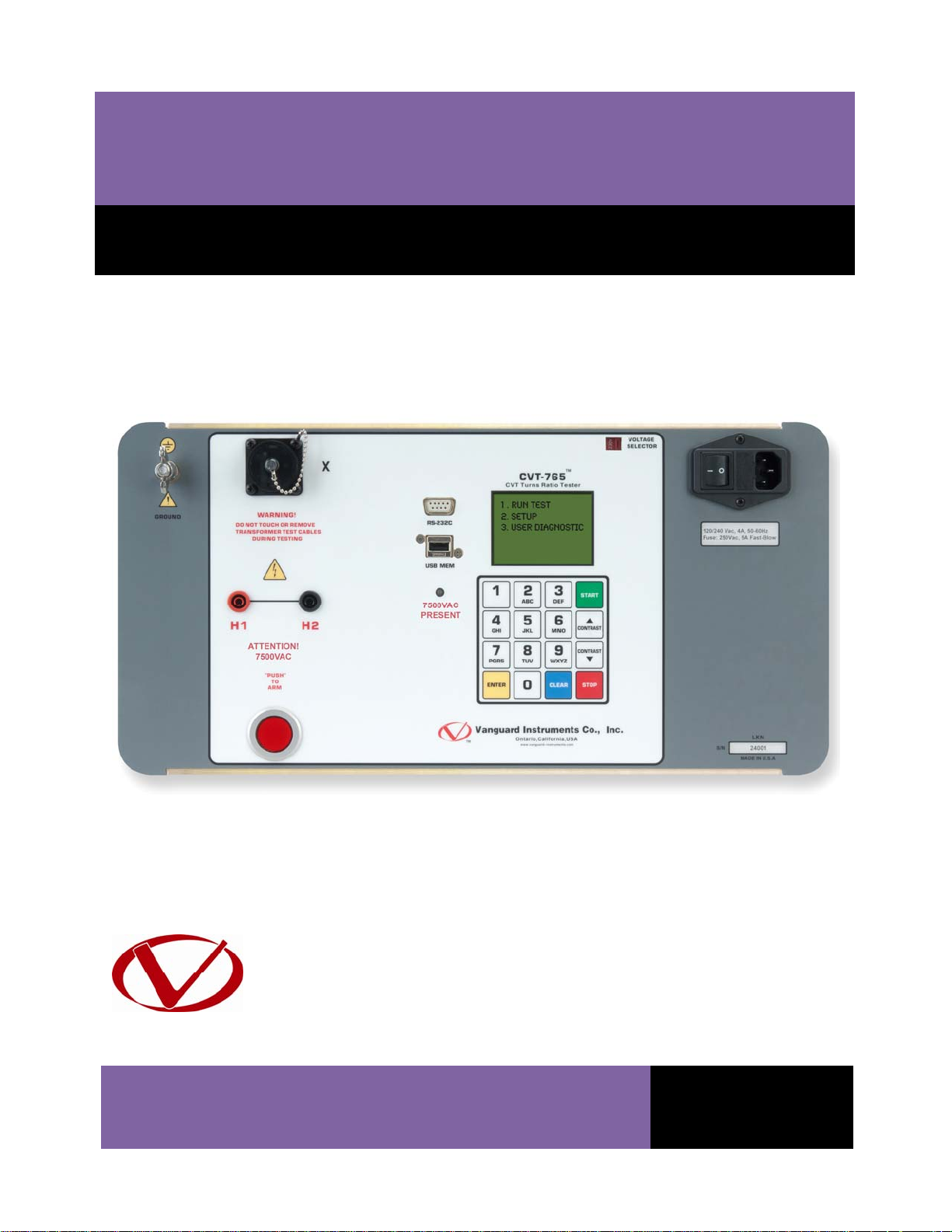
CVT-765
Capacitor Voltage Transformer Ratio Tester
USER’S MANUAL
Vanguard Instruments Company, Inc.
1520 S. Hellman Ave.
Ontario, California 91761, USA
TEL: (909) 923-9390
FAX: (909) 923-9391
May 2011
Revision 1
Page 2

CVT-765 USER’S MANUAL REV 1
SAFETY SUMMARY
FOLLOW EXACT OPERATING PROCEDURES
Any deviation from procedures described in this User’s Manual may create one or more safety
hazards, damage the CVT-765, damage the test transformer, or cause errors in the test results.
Vanguard Instruments Company, Inc. assumes no liability for unsafe or improper use of the
CVT-765.
SAFETY WARNINGS AND CAUTIONS
The CVT-765 shall be used only by trained operators. All transformers under test shall be offline and fully isolated. Always ground the CVT-765 to a substation ground before connecting
the test cables to a transformer. Do not perform test procedures or service unless another
person is also present who is capable of rendering aid and resuscitation.
DO NOT MODIFY TEST EQUIPMENT
To avoid the risk of introducing additional or unknown hazards, do not install substitute parts or
perform any unauthorized modification to any CVT-765 test unit. To ensure that all designed
safety features are maintained, it is highly recommended that repairs be performed only by
Vanguard Instruments Company factory personnel or by an authorized repair service provider.
Unauthorized modifications can cause safety hazards and will void the manufacturer’s
warranty.
WARNING
Do not remove test leads during a test. Failure to heed this warning can result in electrical
shock to personnel and damage to the equipment.
i
Page 3

REV 1 CVT-765 USER’S MANUAL
TABLE OF CONTENTS
CONVENTIONS USED IN THIS DOCUMENT ..................................................................................... 1
1.0 INTRODUCTION .................................................................................................................. .. 2
1.1 General Description and Features ................................................................................... 2
1.2 Technical Specifications ................................................................................................... 3
1.3 Controls and Indicators .................................................................................................... 4
2.0 PRE-TEST SETUP ................................................................................................................... 6
2.1 Operating Voltages .......................................................................................................... 6
2.2 LCD Screen Contrast Control ............................................................................................ 6
3.0 OPERATING PROCEDURES ................................................................................................... 7
3.1 Connection Diagram ........................................................................................................ 7
3.2 Setting the Date and Time ............................................................................................... 8
3.3 Setting the Interface Language ........................................................................................ 9
3.4 Setting the Frequency (50 or 60 Hz) .............................................................................. 10
3.5 Performing Tests ............................................................................................................ 11
3.5.1. Entering Test Record Header Information ............................................................. 11
3.5.2. Performing a Transformer Test .............................................................................. 15
3.6 Working With Test Records ........................................................................................... 20
3.6.1. Viewing the Contents of the Working Memory ..................................................... 20
3.6.2. Saving Test Results to a Test Record ...................................................................... 21
3.6.3. Restoring a Test Record From Flash EEPROM ........................................................ 24
3.6.4. Restoring a Test Record From a USB Flash Drive ................................................... 28
3.6.5. Copying Test Records to a USB Flash Drive ............................................................ 31
3.6.6. Viewing the Test Record Directory ......................................................................... 34
3.6.7. Erasing Test Records from the Flash EEPROM ....................................................... 36
3.6.8. Erasing Test Records from a USB Flash Drive ......................................................... 40
LIST OF TABLES
Table 1. CVT-765 Technical Specifications ...................................................................................... 3
Table 2. Functional Descriptions of CVT-765 Controls and Indicators ........................................... 5
LIST OF FIGURES
Figure 1. CVT-765 Controls and Indicators ..................................................................................... 4
Figure 2. Typical CVT-765 Cable Connections ................................................................................. 7
ii
Page 4
CVT-765 USER’S MANUAL REV 1
CONVENTIONS USED IN THIS DOCUMENT
This document uses the following conventions:
• A key, switch, or knob on the CVT-765 is indicated as [KEY], [SWITCH], [KNOB].
Menu names are referenced as “MENU NAME”
•
• CVT-765 LCD screen output is shown as:
1. OPTION 1
2. OPTION 2
3. OPTION 3
4. OPTION 4
5. OPTION 5
• When instructions are provided, the menu item that should be selected is outlined with a
rectangle as shown below (option 3 should be selected):
1. OPTION 1
2. OPTION 2
3. OPTION 3
4. OPTION 4
5. OPTION 5
• Warning messages are indicated as:
Warning message
WARNING
• Important notes are indicated as:
Note details
NOTE
1
Page 5

REV 1 CVT-765 USER’S MANUAL
1.0 INTRODUCTION
1.1 General Description and Features
The Vanguard CVT-765 is a microprocessor-based, single phase, automatic, transformer turnsratio tester. This portable test unit is specifically designed to measure the turns-ratios of
Capacitor Voltage Transformers (CVT’s).
The CVT-765 determines the transformer turns-ratio using the IEEE C57.12.90 measuring
method. It uses a 7500Vac excitation voltage source to accurately measure the turns-ratio of
Capacitor Voltage Transformers with a rating of up to 765KV. The transformer turns-ratio is
determined by precisely measuring the voltages across the unloaded transformer windings.
The CVT-765 can measure the turns-ratios of Capacitor Voltage Transformers ranging from 75
to 15,000. The measured turns-ratio, winding polarity, and winding phase angle are displayed
on the unit’s LCD screen.
A transformer’s nameplate voltages can also be entered, and the CVT-765 will display the turnsratio percentage error by comparing the test results with the nameplate voltage values. This
convenient feature eliminates any user-calculation errors when testing transformers.
User Interface
The CVT-765 features a back-lit LCD screen (128 x 64 pixels) that is viewable in bright sunlight
and low-light conditions. A rugged 16-key membrane keypad is used to enter test information
and to operate the unit.
Test Record Storage
The CVT-765 can store 128 records of 33 readings internally, and up to 999 test records on an
external USB Flash drive. Test records can be recalled using the included Transformer Analysis
PC Software.
Computer Interface
A Windows® based (XP/Vista/7) Transformer Analysis Software is provided with each unit and
can be used to remotely control the CVT-765 via the RS-232C port. Using this software, the user
can retrieve test records (from the CVT-765’s memory or a USB Flash drive), analyze test
results, and print test results on a desktop printer. Test results are automatically exported to
PDF, EXCEL, and XML formats.
Operating Voltage
The CVT-765 can be operated from 100-120Vac or 220-240Vac. The proper voltage can be set
using the voltage selection switch on the front panel.
2
Page 6

CVT-765 USER’S MANUAL REV 1
1.2 Technical Specifications
Table 1. CVT-765 Technical Specifications
TYPE Portable, automatic, CVT, VT, PT turns-ratio tester
PHYSICAL SPECIFICATIONS Dimensions: 19.5" x 12" x 17" D (49.5 cm x 30.5 cm x 43.2 cm)
Weight: 55 lbs. (24.9 Kg)
INPUT POWER 100-120 Vac or 220-240 Vac (selectable), 50/60 hz
MEASUREMENT METHOD ANSI/IEEE C57.12.90
RATIO MEASURING RANGE 75 - 15,000 (5 digit resolution)
TURNS-RATIO ACCURACY 75 - 4,999: ±0.25%, 5,000 - 9,999: ±0.35%, 10,000 - 15,000: ±0.5%
PHASE ANGLE READING 0-360 degrees, ±0.1 degree accuracy
POLARITY In-Phase or Out-of-Phase indication
TEST VOLTAGE
DISPLAY Back-lit LCD (128 x 64 pixels), viewable in direct sunlight and lo w light levels
COMPUTER INTERFACE RS-232C
PC SOFTWARE Windows XP/Vista/7 Transformer Analysis Software (included with purchase)
INTERNAL TEST RECORD
STORAGE
EXTERNAL TEST RECORD
STORAGE
SAFETY Designed to meet IEC 61010A-1 and CAN/CSA C22.2 No. 1010.1-92
ENVIRONMENT Operating: -10˚ to 50˚ C (15˚ to +122˚ F);
HUMIDITY (MAX) 90% RH @ 40˚ C (104˚ F) non-condensing
ALTITUDE (MAX) 2000m (6562 ft) to fully safety specifications
CABLES One 50 ft. H cable, one 15 ft. X cable, one power cable, one safety ground
WARRANTY One year on parts and labor
7440Vac @ 50ma
128 test records. Each record contains 33 readings.
Up to 999 test records on external USB Flash drive.
Standards
Storage: -30˚ C to 70˚ C (-22˚ to +158˚ F)
cable
The above specifications are valid at nominal operating voltage and at a
temperature of 25°C (77°F). Specifications may change without prior notice.
NOTE
3
Page 7
REV 1 CVT-765 USER’S MANUAL
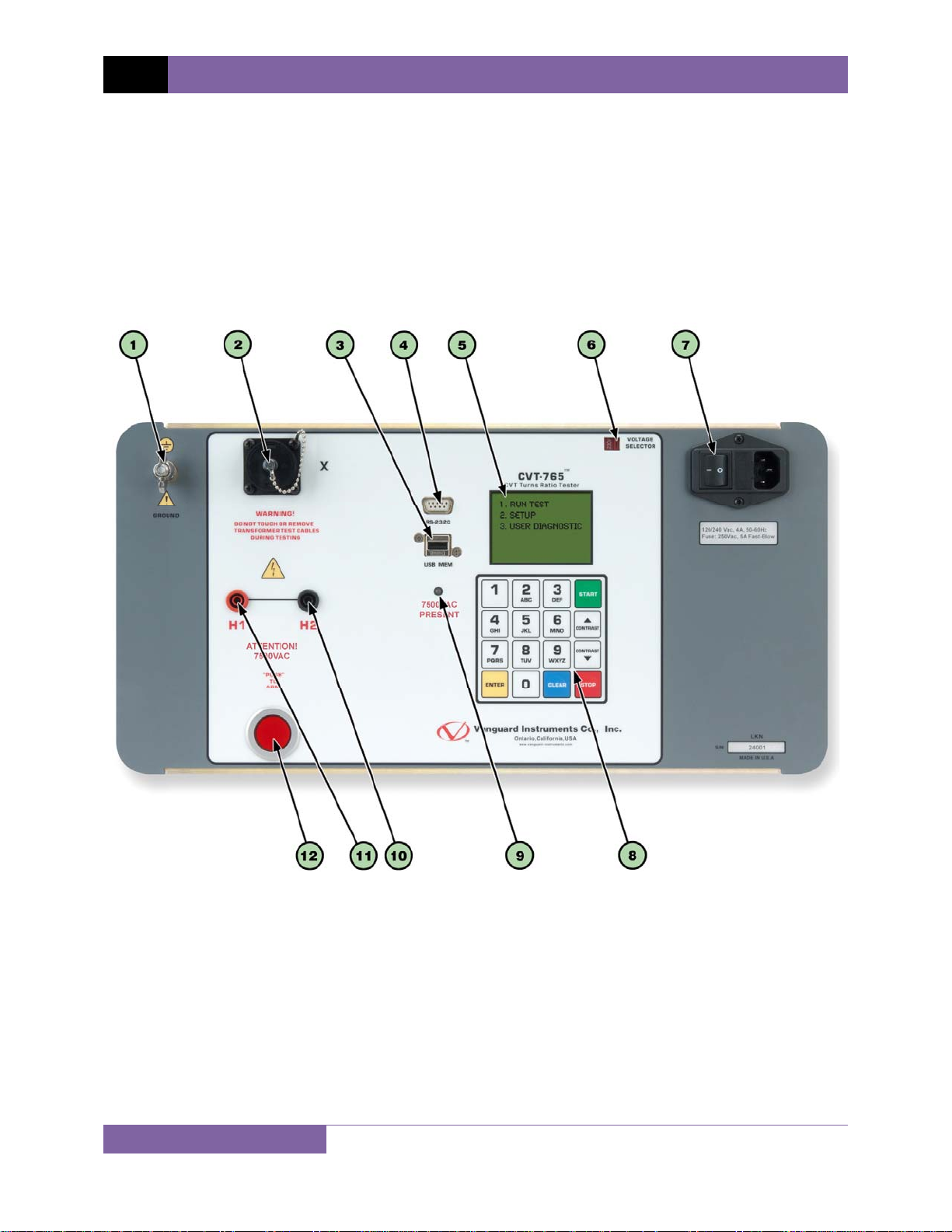
1.3 Controls and Indicators
The CVT-765 controls and indicators are shown in Figure 1. A leader line with an index number
points to each control and indicator, which is cross-referenced to a functional description in the
corresponding table. The purpose of the controls and indicators may seem obvious, but users
should familiarize themselves with them before using the CVT-765. Accidental misuse of the
controls will usually cause no serious harm. Users should also familiarize themselves with the
safety summary information found on the front page of this User’s Manual.
4
Figure 1. CVT-765 Controls and Indicators
Page 8

CVT-765 USER’S MANUAL REV 1
Table 2. Functional Descriptions of CVT-765 Controls and Indicators
Item
Number
1
2
3
4
5
6
7
8
9
10
11
12
Panel Markings Functional Description
GROUND Ground stud for connecting to sub-station ground
X X voltage connector
USB MEM USB Flash drive interface port
RS-232C RS-232C computer interface port
VOLTAGE
SELECTOR
120/240 Vac, 4A, 50-60 Hz
Fuse: 250Vac, 5A Fast Blow
Rugged alpha-numeric keypad
7500VAC
PRESENT
H2 H2 voltage connector
H1 H1 voltage connector
“PUSH”
TO
ARM
Back-lit LCD screen (128 x 64 pixels), viewable in direct light and low
light conditions
Voltage selection switch
Input power connector and fused power sw itch w ith third-w ire sa fe ty
ground
7500VAC hazard warning LED. This LED will be lit when a test is
being performed to remind the user that 7500VAC is presen t.
Spring-loaded push button switch. Pre ss and hold to ini tia te a te st.
5
Page 9

REV 1 CVT-765 USER’S MANUAL
2.0 PRE-TEST SETUP
2.1 Operating Voltages
The CVT-765 can be operated from 100-120 Vac or 220-240 Vac. The proper voltage can be set
using the voltage selection switch on the front panel (see Figure 1).
2.2 LCD Screen Contrast Control
To increase the LCD screen contrast, press and hold the [Contrast ∧] key for two seconds.
Release the button when the desired contrast level has been reached.
To decrease the LCD screen contrast, press and hold the [Contrast ∨] key for two seconds.
Release the button when the desired contrast level has been reached.
6
Page 10
CVT-765 USER’S MANUAL REV 1
3.0 OPERATING PROCEDURES
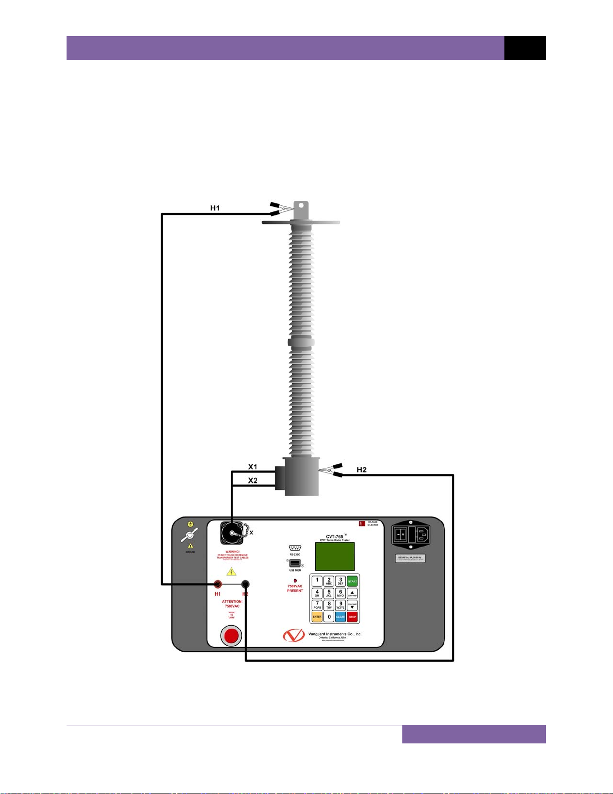
The CVT-765 should always be grounded with the provided ground cable before connecting H
and X cables. The transformer bushings should also be grounded before connecting test leads
to the transformer. This will prevent inducing any voltages into the CVT-765. All transformer
bus connections must be removed, and the transformer must be isolated before performing
any tests.
3.1 Connection Diagram
Figure 2. Typical CVT-765 Cable Connections
7
Page 11

REV 1 CVT-765 USER’S MANUAL
3.2 Setting the Date and Time
To set the date and time:
a. Start from the “START-UP” menu:
1. TEST TRANSFORMER
2. SETUP
TIME: 15:16:17
DATE: 05/17/11
Press the [2] key (SETUP).
b. The following screen will be displayed:
1. RECORD ID
2. SET 50/60 HZ
3. DISPLAY RECORD
4. SAVE/RESTORE RECORD
5. SET TIME
6. set language
Press the [5] key (SET TIME).
c. The following screen will be displayed:
ENTER DATE
MM-DD-YY
Enter the date using the alpha-numeric keypad.
d. The following screen will be displayed:
ENTER TIME
HH:MM:SS
Enter the current time using the alpha-numeric keypad. When the complete time has
been entered, you will be immediately returned to the “START-UP” menu.
8
Page 12

CVT-765 USER’S MANUAL REV 1
3.3 Setting the Interface Language
Follow the steps below to set the interface language (English, Spanish, or Turkish):
a. Start from the “START-UP” menu:
1. TEST TRANSFORMER
2. SETUP
TIME: 15:16:17
DATE: 05/17/11
Press the [2] key (SETUP)
b. The following screen will be displayed:
1. RECORD ID
2. SET 50/60 HZ
3. DISPLAY RECORD
4. SAVE/RESTORE RECORD
5. SET TIME
6. set language
Press the [6] key (SET LANGUAGE)
c. The following screen will be displayed:
1. ENGLISH
2. TURKISH
3. SPANISH
Select the preferred interface language by pressing the corresponding key on the
keypad ([1], [2], or [3]). The interface language will be set and a confirmation screen
will be displayed as shown below:
ENGLISH SET
Press any key to return to the “START-UP” menu.
9
Page 13

REV 1 CVT-765 USER’S MANUAL
3.4 Setting the Frequency (50 or 60 Hz)
Follow the steps below to set the preferred frequency:
a. Start from the “START-UP” menu:
1. TEST TRANSFORMER
2. SETUP
TIME: 15:16:17
DATE: 05/17/11
Press the [2] key (SETUP).
b. The following screen will be displayed:
1. RECORD ID
2. SET 50/60 HZ
3. DISPLAY RECORD
4. SAVE/RESTORE RECORD
5. SET TIME
6. set language
Press the [2] key (SET 50/60 HZ).
c. The following screen will be displayed:
1. 60 Hz
2. 50 hz
Select the preferred frequency by pressing the corresponding key on the keypad (
[2]). The frequency will be set and a confirmation screen will be displayed as shown
below:
60 hz set
[1] or
Press any key to return to the “START-UP” menu.
10
Page 14

CVT-765 USER’S MANUAL REV 1
3.5 Performing Tests
3.5.1. Entering Test Record Header Information
You can enter the test record header information before performing tests. The record header
includes identifying information such as the company, station, circuit, manufacturer, etc. Once
the header information has been set, it will apply to all subsequent test records. To enter the
header information:
a. Start from the “START-UP” menu:
1. TEST TRANSFORMER
2. SETUP
TIME: 15:16:17
DATE: 05/17/11
Press the [2] key (SETUP).
b. The following screen will be displayed:
1. RECORD ID
2. SET 50/60 HZ
3. DISPLAY RECORD
4. SAVE/RESTORE RECORD
5. SET TIME
6. set language
Press the [1] key (RECORD ID).
c. The following screen will be displayed:
COMPANY:
_
↑/↓ TO POSITION
"ENTER" TO ACCEPT
Type the company name using the alpha-numeric keypad.
When pressing a key, the corresponding number on the key will be displayed first.
Pressing the key again will display the first letter on the key. Pressing the key again will
display the second letter on the key. For example, to type the letter “A”, you must press
the [2] key twice. To erase the character at the cursor position, press the [CLEAR] key.
Press the [Contrast ∧] key to move to the next character. Press the [Contrast ∨]
11
Page 15

REV 1 CVT-765 USER’S MANUAL
key to move to the previous character. Press the [ENTER] key when you are done
typing the company name.
d. The following screen will be displayed:
STATION:
_
↑/↓ TO POSITION
"ENTER" TO ACCEPT
Type the station name using the alpha-numeric keypad and then press the [ENTER]
key.
e. The following screen will be displayed:
CIRCUIT:
_
↑/↓ TO POSITION
"ENTER" TO ACCEPT
Type the circuit information using the alpha-numeric keypad and then press the
[ENTER] key.
f. The following screen will be displayed:
MANUFACTURER:
_
↑/↓ TO POSITION
"ENTER" TO ACCEPT
Type the manufacturer name using the alpha-numeric keypad and then press the
[ENTER] key.
12
Page 16

g. The following screen will be displayed:
MODEL:
_
↑/↓ TO POSITION
"ENTER" TO ACCEPT
Type the transformer’s model information using the alpha-numeric keypad and then
press the [ENTER] key.
h. The following screen will be displayed:
SERIAL NUMBER:
_
↑/↓ TO POSITION
"ENTER" TO ACCEPT
CVT-765 USER’S MANUAL REV 1
Type the transformer’s serial number using the alpha-numeric keypad and then press
the [ENTER] key.
i. The following screen will be displayed:
KVA RATING:
_
↑/↓ TO POSITION
"ENTER" TO ACCEPT
Type the transformer’s KVA rating using the alpha-numeric keypad and then press the
ENTER] key.
[
13
Page 17

REV 1 CVT-765 USER’S MANUAL
j. The following screen will be displayed:
OPERATOR:
_
↑/↓ TO POSITION
"ENTER" TO ACCEPT
Type the operator’s name using the alpha-numeric keypad and then press the [ENTER]
key. All header information will be saved, and you will be returned to the “START-UP”
menu.
14
Page 18

3.5.2. Performing a Transformer Test
Follow the steps below to test a transformer:
a. Start from the “START-UP” menu:
1. TEST TRANSFORMER
2. SETUP
TIME: 15:16:17
DATE: 05/17/11
Press the [1] key (TEST TRANSFORMER).
b. The following screen will be displayed:
TEST WINDING:
1.X1-X3 2.X2-X3
3.Y1-Y3 4.Y2-Y3
5.Z1-Z3 6.Z2-Z3
CVT-765 USER’S MANUAL REV 1
Select the winding by pressing the corresponding numeric key on the keypad.
c. The following screen will be displayed:
NAME PLATE VOLTAGE?
1. YES
2. NO
If you had entered name plate voltages for a previous test, the following
screen will be displayed instead of the above screen:
NOTE
NAME PLATE VOLTAGE?
1. YES
2. NO
3. USE PREV DATA
Press the [3] key if you would like to use the name plate voltage values from
the previous test performed. Continue to step c.
15
Page 19

REV 1 CVT-765 USER’S MANUAL
1. YES
Press the [1] key (YES) if you would like to enter the transformer name plate
voltage values. The following screen will be displayed.
NAME PLATE VOLTAGE:
H : X
0 :
Type the H winding name plate voltage value using the numeric keypad. The
screen will be updated as shown below:
NAME PLATE VOLTAGE:
H : X
2,400 :
Press the [ENTER] key. The screen will be updated as shown below:
NAME PLATE VOLTAGE:
H : X
2,400 : 0
Type the X winding name plate voltage value using the numeric keypad. The
screen will be updated as shown below:
NAME PLATE VOLTAGE:
H : X
2,400 : 240
Press the [ENTER] key. Continue to step c.
2. NO
Press the
voltage values. Continue to step c.
16
[2] key (NO) if you do not want to enter the transformer name plate
Page 20

CVT-765 USER’S MANUAL REV 1
d. The following screen will be displayed:
PRESS AND HOLD ARM
SWITCH TO TEST
OR
"STOP" TO ABORT
Press and hold the [ARM] switch to initiate the test.
e. The following screen will be displayed while the test is being performed:
test in progress
please wait...
Continue to hold down the [ARM] switch. Testing will continue, and the test results will
be displayed on the LCD screen when testing has finished:
RATIO %DIFF
+10.004 0.04
PHASE = 0.02°
You can now release the
[ARM] switch.
The polarity is displayed as either a plus sign (+) for “in-phase” or a minus sign (-) for
“out-of-phase”. The value listed under “% DIFF” is the percentage error.
The percentage error (% DIFF) is calculated as the absolute value of:
[(Calculated Ratio – Measured Ratio) / Calculated Ratio)] x 100
NOTE
Press any key to continue.
17
Page 21

REV 1 CVT-765 USER’S MANUAL
f. The following screen will be displayed:
KEEP THIS READING?
1. YES
2. NO
Press the [1] key (YES) to save the reading.
g. The following screen will be displayed:
TEST SAVED
Press any key to continue.
The above screen will be displayed if there is currently no data in the unit’s
memory buffer. If a test was previously performed or a test record was
NOTE
restored from Flash EEPROM or from a Flash drive, the following screen will
be displayed instead:
Press the [1] key (APPEND PREV. DATA) to append the data in the unit’s
working memory to the current test results, or press the [2] key (CLEAR PREV.
DATA) to clear any previous data from the unit’s memory buffer and only save
the current test results.
The following screen will then be displayed:
Press any key to continue.
18
PREVIOUS DATA IN BUF
1. APPEND PREV. DATA
2. CLEAR PREV. DATA
TEST SAVED
Page 22

h. The following screen will be displayed:
RUN ANOTHER TEST?
1. YES
2. NO
3. REPEAT PREV. TEST
Press the [2] key (NO).
i. The following screen will be displayed:
SAVE THIS RECORD?
1. YES
2. NO
CVT-765 USER’S MANUAL REV 1
Press the [1] key (YES) to save the test record to the unit’s Flash EEPROM.
j. The following screen will be displayed momentarily:
SAVING RECORD...
PLEASE WAIT...
The following confirmation screen will then be displayed:
RECORD NUMBER 1
HAS BEEN SAVED!
The unit will automatically assign the record number and will not over-write
existing test records.
NOTE
Press any key to return to the “START-UP” menu.
19
Page 23

REV 1 CVT-765 USER’S MANUAL
3.6 Working With Test Records
3.6.1. Viewing the Contents of the Working Memory
Whenever a test is performed or a test record is retrieved, the data is stored in the CVT-765’s
working memory. You can view the test data using the steps below:
a. Start from the “START-UP” menu:
1. TEST TRANSFORMER
2. SETUP
TIME: 15:16:17
DATE: 05/17/11
Press the [2] key (SETUP).
b. The following screen will be displayed:
1. RECORD ID
2. SET 50/60 HZ
3. DISPLAY RECORD
4. SAVE/RESTORE RECORD
5. SET TIME
6. set language
Press the [3] key (DISPLAY RECORD).
c. The basic test record information will be displayed as shown:
SINGLE PHASE
Num Tests: 1
04/15/11 09:52:50
d. Press the [Contrast ∨] key. The test record details will be displayed as shown below:
1 SINGLE PHASE
7440 volts
RATIO %DIFF
10.004 0.04
Press the
[STOP] key to return to the “START-UP” menu.
20
Page 24

CVT-765 USER’S MANUAL REV 1
3.6.2. Saving Test Results to a Test Record
After performing a test, the user is presented the option to save the test results to the unit’s
Flash EEPROM or to a USB Flash Drive. If the test results are not saved immediately after
performing a test, they will still remain in the working memory and can be saved later, as long
as a new test has not been performed and the unit has not been turned off. Follow the steps
below to save the test results from the working memory to a test record (the following
procedure can also be used to re-save a restored test record to a new memory location or to a
USB Flash Drive):
a. Perform a test or restore a test record to the working memory (see section 3.6.3 and
3.6.4), and then start from the “START-UP” menu:
1. TEST TRANSFORMER
2. SETUP
TIME: 15:16:17
DATE: 05/17/11
Press the [2] key (SETUP).
b. The following screen will be displayed:
1. RECORD ID
2. SET 50/60 HZ
3. DISPLAY RECORD
4. SAVE/RESTORE RECORD
5. SET TIME
6. set language
Press the [4] key (SAVE/RESTORE RECORD).
21
Page 25

REV 1 CVT-765 USER’S MANUAL
c. The following screen will be displayed:
1. RESTORE RECORD
2. SAVE RECORD
3. RECORD DIRECTORY
4. ERASE RECORD
5. COPY to THUMB DRIVE
Option 5 (COPY TO THUMB DRIVE) will be listed only if a USB Flash drive is
connected to the CVT-765.
NOTE
Press the [2] key (SAVE RECORD).
If a USB Flash drive is connected to the unit, continue to step d.
If a USB Flash drive is NOT connected to the unit, continue to step e.
d. The following screen will be displayed:
1. SAVE INTERNALLY
2. SAVE TO THUMB DRIVE
1. SAVE INTERNALLY
Press the [1] key (SAVE INTERNALLY) to save the test record to the unit’s Flash
EEPROM. Continue to step e.
2. SAVE TO THUMB DRIVE
Press the
[2] key (SAVE TO THUMB DRIVE) to save the test record to the
connected USB Flash drive. The following screen will be displayed:
REC_001 SAVED TO
THUMB DRIVE.
Press any key to return to the “START-UP” menu.
22
Page 26

e. The following screen will be displayed:
RECORD NUMBER 5
HAS BEEN SAVED!
Press any key to return to the “START-UP” menu.
CVT-765 USER’S MANUAL REV 1
23
Page 27

REV 1 CVT-765 USER’S MANUAL
3.6.3. Restoring a Test Record From Flash EEPROM
Use the steps below to restore a test record from the CVT-765’s Flash EEPROM to the working
memory:
a. Start from the “START-UP” menu:
1. TEST TRANSFORMER
2. SETUP
TIME: 15:16:17
DATE: 05/17/11
Press the [2] key (SETUP).
b. The following screen will be displayed:
1. RECORD ID
2. SET 50/60 HZ
3. DISPLAY RECORD
4. SAVE/RESTORE RECORD
5. SET TIME
6. set language
Press the [4] key (SAVE/RESTORE RECORD).
c. The following screen will be displayed:
1. RESTORE RECORD
2. SAVE RECORD
3. RECORD DIRECTORY
4. ERASE RECORD
5. COPY to THUMB DRIVE
Option 5 (COPY TO THUMB DRIVE) will be listed only if a USB Flash drive is
connected to the CVT-765.
NOTE
Press the [1] key (RESTORE RECORD).
24
Page 28

d. The following screen will be displayed:
RESTORE RECORD
1.ENTER RECORD NUMBER
2.SCROLL TO SELECT
If you have a USB Flash drive inserted in the CVT-765’s “USB MEM” port, the
following screen will be displayed instead of the above screen:
NOTE
1.INTERNAL STORAGE
2.THUMB DRIVE
Press the [1] key (INTERNAL STORAGE).
CVT-765 USER’S MANUAL REV 1
The following screen will be displayed:
RESTORE RECORD
1.ENTER RECORD NUMBER
2.SCROLL TO SELECT
Continue with the steps below.
1. ENTER RECORD NUMBER
Press the [1] key (ENTER RECORD NUMBER) if you know the record number that
you would like to restore.
1.1. The following screen will be displayed:
RESTORE RECORD
NUMBER:
Type the record number using the alpha-numeric keypad and then press
[ENTER] key.
the
25
Page 29

REV 1 CVT-765 USER’S MANUAL
1.2. The following screen will be displayed:
RECORD RESTORED!
DISPLAY RECORD?
1.YES
2.NO
Press the [1] key (YES) to display the test record.
1.3. The basic information about the restored test record will be displayed as
shown:
SINGLE PHASE
Num Tests: 1
04/15/11 09:52:50
Press the [Contrast ∨] key. The test record details will be displayed as
shown:
1 SINGLE PHASE
7440 volts
RATIO %DIFF
10.004 0.04
Press the
[STOP] key to return to the “START-UP” menu. The restored
test record will remain loaded in the working memory.
2. SCROLL TO SELECT
Press the [2] key (SCROLL TO SELECT) to scroll through a directory of the stored
test records.
2.1. The following screen will be displayed:
RECORDS DIRECTORY
"UP" TO SCROLL FWD
"DWN" TO SCROLL RVS
26
Page 30

CVT-765 USER’S MANUAL REV 1
Press the [Contrast ∧] button or the [Contrast ∨] key to display the
next or previous test record, respectively.
The basic test record information will be displayed as shown:
#1 04/15/11 09:52
SINGLE PHASE
1 TESTS
When you have located the test record that you would like to restored,
press the
[ENTER] key. Continue to step 1.2 on page 26.
27
Page 31

REV 1 CVT-765 USER’S MANUAL
3.6.4. Restoring a Test Record From a USB Flash Drive
Use the steps below to restore a test record from a USB Flash drive to the CVT-765’s working
memory:
a. Make sure the USB Flash drive containing the test record(s) is inserted in the CVT-765’s
USB Flash drive port (“USB MEM” port). Then start from the “START-UP” menu:
1. TEST TRANSFORMER
2. SETUP
TIME: 15:16:17
DATE: 05/17/11
Press the [2] key (SETUP).
b. The following screen will be displayed:
1. RECORD ID
2. SET 50/60 HZ
3. DISPLAY RECORD
4. SAVE/RESTORE RECORD
5. SET TIME
6. set language
Press the [4] key (SAVE/RESTORE RECORD).
c. The following screen will be displayed:
1. RESTORE RECORD
2. SAVE RECORD
3. RECORD DIRECTORY
4. ERASE RECORD
5. COPY TO THUMB DRIVE
Press the [1] key (RESTORE RECORD).
28
Page 32

d. The following screen will be displayed:
1.INTERNAL STORAGE
2.THUMB DRIVE
Press the [2] key (THUMB DRIVE).
e. The following screen will be displayed:
RESTORE THUMB DRIVE
REC_
CVT-765 USER’S MANUAL REV 1
Type the record number that you would like to restore using the alpha-numeric keypad
and then press the [ENTER] key.
f. The test record will be restored to the unit’s working memory and the following screen
will be displayed:
REC_000 restored!
DISPLAY RECORD?
1.YES
2.NO
Press the
[1] key (YES) to display the restored test record.
g. The basic information about the restored test record will be displayed as shown below:
SINGLE PHASE
Num Tests: 1
04/15/11 09:52:50
29
Page 33

REV 1 CVT-765 USER’S MANUAL
Press the [Contrast ∨] key. The test record details will be displayed as shown below:
1 SINGLE PHASE
7440 volts
RATIO %DIFF
10.004 0.04
Press the [STOP] key to return to the “START-UP” menu. The restored test record will
remain loaded in the working memory.
30
Page 34

CVT-765 USER’S MANUAL REV 1
3.6.5. Copying Test Records to a USB Flash Drive
Use the steps below to copy one or all test records from the unit’s Flash EEPROM to a
connected USB Flash drive:
a. Make sure a USB Flash drive is connected to the unit’s “USB MEM” port, and then start
from the “START-UP” menu:
1. TEST TRANSFORMER
2. SETUP
TIME: 15:16:17
DATE: 05/17/11
Press the [2] key (SETUP).
b. The following screen will be displayed:
1. RECORD ID
2. SET 50/60 HZ
3. DISPLAY RECORD
4. SAVE/RESTORE RECORD
5. SET TIME
6. set language
Press the [4] key (SAVE/RESTORE RECORD).
c. The following screen will be displayed:
1. RESTORE RECORD
2. SAVE RECORD
3. RECORD DIRECTORY
4. ERASE RECORD
5. COPY TO THUMB DRIVE
Press the [5] key (COPY TO THUMB DRIVE).
31
Page 35

REV 1 CVT-765 USER’S MANUAL
d. The following screen will be displayed:
COPY REC TO THUMB DRV
1.COPY SINGLE RECORD
2.COPY ALL RECORDS
1. COPY SINGLE RECORD
Press the [1] key (COPY SINGLE RECORD) to copy a single test record from the
CVT-765’s Flash EEPROM to the connected USB Flash drive. The following screen
will be displayed:
ENTER RECORD NUMBER
TO COPY TO FLASH DRV
NUMBER:
Type the record number using the alpha-numeric keypad and then press the
[ENTER] key. The test record will be copied to the USB Flash drive and the
following screen will be displayed:
REC_000 SAVED TO
THUMB DRIVE
Press any key to return to the “START-UP” menu.
2. COPY ALL RECORDS
Press the
[2] key (COPY ALL RECORDS) to copy all test records from the CVT-
765’s Flash EEPROM to the connected USB Flash drive. All test records will be
copied from the unit to the connected USB Flash drive. The following screen will
be displayed when the process is finished:
32
Page 36

CVT-765 USER’S MANUAL REV 1
ALL RECORDS HAVE BEEN
TRANSFERRED TO THUMB
DRIVE!
Press any key to return to the “START-UP” menu.
33
Page 37

REV 1 CVT-765 USER’S MANUAL
3.6.6. Viewing the Test Record Directory
Use the steps below to browse through a directory of the test records stored in the CVT-765’s
Flash EEPROM memory:
a. Start from the “START-UP” menu:
1. TEST TRANSFORMER
2. SETUP
TIME: 15:16:17
DATE: 05/17/11
Press the [2] key (SETUP)
b. The following screen will be displayed:
1. RECORD ID
2. SET 50/60 HZ
3. DISPLAY RECORD
4. SAVE/RESTORE RECORD
5. SET TIME
6. set language
Press the [4] key (SAVE/RESTORE RECORD).
c. The following screen will be displayed:
1. RESTORE RECORD
2. SAVE RECORD
3. RECORD DIRECTORY
4. ERASE RECORD
5. COPY TO THUMB DRIVE
Option 5 (COPY TO THUMB DRIVE) is listed only if a USB Flash drive is
connected to the unit.
NOTE
Press the [3] key (RECORD DIRECTORY)
34
Page 38

d. The following screen will be displayed:
RECORDS DIRECTORY
"UP" TO SCROLL FWD
"DWN" TO SCROLL RVS
Press the [Contrast ∧] or [Contrast ∨] key to scroll through the test record
directory. The test record header will be displayed as shown:
SINGLE PHASE
Num Tests: 1
04/15/11 09:52:50
CVT-765 USER’S MANUAL REV 1
You can continue to scroll through the record directory by pressing the [Contrast ∧]
and [Contrast ∨] keys. Press the [STOP] key to return to the “START-UP” menu.
35
Page 39

REV 1 CVT-765 USER’S MANUAL
3.6.7. Erasing Test Records from the Flash EEPROM
Follow the steps below to erase test records from the Flash EEPROM:
a. Start from the “START-UP” menu:
1. TEST TRANSFORMER
2. SETUP
TIME: 15:16:17
DATE: 05/17/11
Press the [2] key (SETUP).
b. The following screen will be displayed:
1. RECORD ID
2. SET 50/60 HZ
3. DISPLAY RECORD
4. SAVE/RESTORE RECORD
5. SET TIME
6. set language
Press the [4] key (SAVE/RESTORE RECORD).
c. The following screen will be displayed:
1. RESTORE RECORD
2. SAVE RECORD
3. RECORD DIRECTORY
4. ERASE RECORD
5. COPY TO THUMB DRIVE
Press the [4] key (ERASE RECORD).
36
Page 40

d. The following screen will be displayed:
ERASE RECORD
1.ERASE SINGLE REC.
2.ERASE ALL RECORDS
"STOP" TO EXIT
If you have a USB Flash drive inserted in the CVT-765’s “USB MEM” port, the
following screen will be displayed instead of the above screen:
NOTE
1.ERASE INTERNAL REC
2.ERASE THUMB DRV REC
Press the [1] key (ERASE INTERNAL REC).
CVT-765 USER’S MANUAL REV 1
The following screen will be displayed:
ERASE RECORD
1.ERASE SINGLE REC.
2.ERASE ALL RECORDS
"STOP" TO EXIT
Continue with the steps below.
1. ERASE SINGLE REC.
Press the
[1] key (ERASE SINGLE REC.) to erase a single test record from the unit’s
internal Flash EEPROM. The following screen will be displayed:
ERASE RECORD
NUMBER:
You can cancel the process and return to the “START-UP” menu by pressing
the [STOP] key.
NOTE
37
Page 41

REV 1 CVT-765 USER’S MANUAL
Type the record number that you would like to erase using the alpha-numeric
keypad and then press the [ENTER] key. If you do not know the test record
number, you can first view the test record directory using the instructions in section
3.6.6.
The following screen will be displayed while the record is being erased:
ERASing record
PLEASE WAIT...
The following screen will be displayed when the test record has been completely
erased:
RECORD NUMBER 8
ERASED!
Press any key to continue. You will be returned to the beginning of step d.
2. ERASE ALL RECORDS
Press the [2] key (ERASE ALL RECORDS) to erase all the test records from the unit’s
internal Flash EEPROM. The following warning screen will be displayed:
ERASE ALL RECORDS!
ARE YOU SURE?
"ENTER" To CONTINUE.
You can press the
[STOP] key to cancel the process and return to the “START-UP”
menu.
Press the
[ENTER] key to proceed with deleting all the test records from the unit’s
Flash EEPROM. The following screen will be displayed during the erasure process:
38
Page 42

CVT-765 USER’S MANUAL REV 1
ERASing recordS
PLEASE WAIT...
The following screen will be displayed when all test records have been completely
erased:
RECORDS ERASED!
Press any key to return to the “START-UP” menu.
39
Page 43

REV 1 CVT-765 USER’S MANUAL
3.6.8. Erasing Test Records from a USB Flash Drive
Follow the steps below to erase test records from a USB Flash drive:
a. Make sure a USB Flash drive is connected to the unit’s “USB MEM” port, and then start
from the “START-UP” menu:
1. TEST TRANSFORMER
2. SETUP
TIME: 15:16:17
DATE: 05/17/11
Press the [2] key (SETUP).
b. The following screen will be displayed:
1. RECORD ID
2. SET 50/60 HZ
3. DISPLAY RECORD
4. SAVE/RESTORE RECORD
5. SET TIME
6. set language
Press the [4] key (SAVE/RESTORE RECORD).
c. The following screen will be displayed:
1. RESTORE RECORD
2. SAVE RECORD
3. RECORD DIRECTORY
4. ERASE RECORD
5. COPY TO THUMB DRIVE
Press the [4] key (ERASE RECORD).
40
Page 44

d. The following screen will be displayed:
1.ERASE INTERNAL REC
2.ERASE THUMB DRV REC
Press the [2] key (ERASE THUMB DRV REC).
e. The following screen will be displayed:
ERASE RECORD
1.ERASE SINGLE REC.
2.ERASE ALL RECORDS
"STOP" TO EXIT
CVT-765 USER’S MANUAL REV 1
1. ERASE SINGLE REC.
Press the [1] key (ERASE SINGLE REC.) to erase a single test record from the
connected USB Flash drive. The following screen will be displayed:
ERASE THUMB DRIVE
REC_
Type the record number that you would like to erase using the alpha-numeric
keypad and then press the
[ENTER] key. The test record will be erased from the
USB Flash drive and the following screen will be displayed:
THUMB DRIVE RE000
ERASED!
Press any key to continue. You will be returned to the beginning of step e. Press the
[STOP] key to return to the “START-UP” menu.
41
Page 45

REV 1 CVT-765 USER’S MANUAL
2. ERASE ALL RECORDS
Press the [2] key (ERASE ALL RECORDS) to delete all test records from the connected
USB Flash drive. The following warning screen will be displayed:
ERASE ALL THUMB DRIVE
RECORDS!
ARE YOU SURE?
"ENTER" TO CONTINUE.
Press the [STOP] key if you do not want to erase all the test records. You will be
returned to the “START-UP” menu.
Press the [ENTER] key to proceed with deleting all the test records from the
connected USB Flash drive. The following screen will be displayed when all the
records have been erased:
all thumb drive
records erased!
Press any key to return to the “START-UP” menu.
42
Page 46

1520 S. Hellman Ave • Ontario, CA 91761 • USA
Phone: 909-923-9390 • Fax: 909-923-9391
www.vanguard-instruments.com
Copyright © 2011 by Vanguard Instruments Company, Inc.
CVT-765 User’s Manual • Revision 1.0 • May 19, 2011 • TA
 Loading...