

Page 1
OPERATING INSTRUCTIONS
for the
CT-7000
Digital Circuit Breaker Analyzer
Vanguard Instruments Company
1710 Grevillea Court
Ontario, California 91761
TEL: (909) 923-9390 October 2003
FAX: (909) 923-9391 Rev 3
Page 2

CT-7000 Operating Instructions
SAFETY WARNINGS AND CAUTIONS
Only trained operators shall use the device. All circuit breakers under test shall be
fully isolated.
DO NOT SERVICE OR TEST ALONE
Do not perform test procedures or service unless another person is also present who is capable
of rendering aid and resuscitation.
DO NOT MODIFY TEST EQUIPMENT
Due to the added risk of introducing additional or unknown hazards, do not install substitute parts
or perform any unauthorized modifications to any CT-7000 test unit. To ensure that all designed
safety features are maintained, it is recommended that repairs be performed only by Vanguard
Instruments Company’s factory personnel or by an authorized repair and service center.
Unauthorized modifications can cause serious safety hazards and will nullify the manufacturer's
warranty.
FOLLOW EXACT OPERATING PROCEDURES
Any deviation from the procedures described in the operator’s manual may create one or more
safety hazards, damage the CT-7000, the test circuit breaker or cause errors in the test results.
Vanguard Instruments Company, Incorporated assumes no liability for unsafe or improper use of
the CT-7000.
off line and
WARRANTY
The CT-7000’s warranty is only valid to the original purchaser to be free from defects in material
and workmanship for a period of one year. The warranty does not apply to normal wear or
damage from misuse, abuse, improper storage, installation, accident, unauthorized repair or
alterations.
Page 3

CT-7000 Operating Instructions
Table of Contents
1.0 Introduction
2.0 CT-7000 Description
2.1 Contact Timing Channels
2.2 Analog Voltage Monitoring Channel
2.3 Digital Voltage Monitoring Channel
2.4 Trip/Close Current Monitoring
2.5 Travel Transducer Input Channels
2.6 Breaker Initiate Capability
2.7 Built-in Thermal Printer
2.8 Computer Interface Capabilities
2.9 Timing Shots Storage Capabilities
2.10 Breaker Test Plan Storage Abilities
2.11 Diagnostic Capabilities
2.12 CT-7000 Display and Control Switches
3.0 Test Result Tabulation
3.1 Electrical Measurement Results
3.2 Mechanical Measurement Results
3.3 Analog Voltage Input Results
3.4 Digital Voltage Input Results
3.5 Initiate Current Results
3.6 Slow-Close Test Results
4.0 Test Result Graphics
4.1 Thermal Printer Graphic Printout
4.2 Ink-jet Printer Output
5.0 CT-7000 Controls and Display
6.0 CT-7000 Analyzer Specifications
7.0 CT-7000 Special Features
7.1 CT-7000 Supplied Cables
7.2 CT-7000 Operating Voltages
7.3 CT-7000 Main Power Fuse
7.4 CT-7000 Printer and Printer Paper
7.5 CT-7000 Printer Paper Control
7.6 Replacing CT-7000 Thermal Paper
7.7 CT-7000 LCD Contrast Control
8.0 Test Hook-up Connections
8.1 Contact Cable Hookup
8.2 Initiate Cable Hookup
8.3 Analog Voltage Monitor Hookup
8.4 Digital Voltage Monitor Hookup
8.5 External Trigger Input
8.6 Transducer Connection
9.0 Operating Procedures
9.1 Timing a Circuit Breaker
9.1.1 Timing an OPEN Operation With No Insertion Resistors
9.1.2 Timing an OPEN Operation With Insertion Resistors
9.1.3 Timing CLOSE-OPEN Operation Using Contact Channel #1
9.1.4 Timing OPEN-CLOSE-OPEN Operation
.................................................................................................................................
..................................................................................................................
..................................................................................................
...............................................................................................................
...................................................................................................
.................................................................................................................
......................................................................................................
...................................................................................................
.........................................................................................................
......................................................................................................
.................................................................................................
....................................................................................................
...................................................................................................
..............................................................................................................
..............................................................................................
................................................................................
.................................................................................
........................................................................................
.................................................................................
...............................................................................................
.....................................................................................
.................................................................................
.............................................................................
.................................................................................................
.......................................................................
....................................................................................
.................................................................................
.........................................................................................
..........................................................................................
...............................................................................................
...................................................................................
...............................................................................................
..............................................................................................
.......................................................................................
..........................................................................................
..............................................................................
....................................................................................
.............................................................................
...................................................................................
....................................................................................
.....................................................................................
...............................................................................................
..............................................................................................
.........................................
..............................................
..................................
.................................................................
1
1
2
2
2
2
2
2
2
2
3
3
3
3
4
4
4
4
5
5
5
5
5
5
6
8
9
9
10
10
10
11
11
11
12
12
14
15
15
16
17
18
19
20
21
22
24
Page 4

CT-7000 Operating Instructions
9.2 Get Tabulated Timing Results Using the Thermal Printer
9.2.1 Tabulated Results Interpretation
9.3 Get Graphic Timing Results Using the Thermal Printer
9.4 Save Timing Shots in the EEPROM
9.5 Printing Timing Shot Directory Stored in the EEPROM
9.6 Recalling a Timing Shot
9.7 Deleting a Timing Shot
9.8 Shot Description
9.9 Computer Interface
9.10 Breaker Travel Analysis
9.10.1 Breaker Stroke
9.10.2 Breaker Over-Travel Distance
9.10.3 Breaker Bounce-Back Distance
9.10.4 Contact Wipe
9.10.5 Breaker Velocity
9.10.6 Analysis Point Selections
9.10.7 Analysis Point No.1 (AP1)
9.10.8 Analysis Point No. 2 (AP2)
9.11 Set-Up Open Analysis Points
9.12 Circuit Breaker Test Plan
9.13 Recall a Breaker Test Plan
9.14 Print a Breaker Test Plan
9.15 Print a Breaker Test Plan Directory
9.16 English/Metric or Rotary Transducer Selection
9.17 Set CT-7000 Internal Clock
9.18 Slow-Close Test
9.19 Transducer Self-Test
9.20 Check Cable Hookup
9.21 Automatic Print Setting
9.22 CT-7000 Channel Configuration
9.23 Running CT-7000 in Tandem
10.0 CT-7000 Trouble Shooting Guide
...........................................................................................................
..........................................................................................................
...............................................................................................
.................................................................................................
......................................................................................................
........................................................................................................
......................................................................................................
.........................................................................................................
.................................................................................................
.................................................................................................
...............................................................................................
...........................................
...............................................................................
..............................................
............................................................................
...............................................
.............................................................................................
................................................................................
.............................................................................
........................................................................................
.......................................................................................
......................................................................................
.....................................................................................
...........................................................................................
........................................................................................
...........................................................................................
...........................................................................
.........................................................
........................................................................................
................................................................................
.....................................................................................
..........................................................................................
25
27
29
36
37
39
40
41
43
44
44
44
44
44
44
44
45
45
47
49
49
51
55
56
57
58
59
60
61
62
63
64
Page 5

CT-7000 Operating Instructions
List of Figures
Figure 1.0 CT-7000 Control Panel
Figure 2.0 Contact Cable Connection
Figure 3.0 Series Contact Cable Connection
Figure 4.0 DC Trip and DC Close, Initiate Circuit Cable Hook-Up
Figure 5.0 DC Trip and AC Close, Initiate Circuit Cable Hook-Up
Figure 6.0 Voltage Monitoring Cable Hook-Up
Figure 7.0 External Trigger Cable Hook-Up
Figure 8.0 Transducer Connection
Figure 9.0 CT-7000 Operating Steps
Figure 10.0 Typical Tabulated Printout of an Open Operation From the Thermal Printer
Figure 11.0 Typical Tabulated Printout of an Open Operation From Ink Jet Printer
Figure 12.0 Typical Graphic Result From the Thermal Printer
Figure 13.0 Typical Graphic Printout From the Ink Jet Printer
Figure 14.0 Expansion Graph From 0 to 200ms From the Thermal Printer
Figure 15.0 Expansion Graph From 0 to 200ms From Ink Jet Printer
Figure 16.0 Graphical Interpretation of an Open Timing Shot
Figure 17.0 Graphical Interpretation of a Close Timing Shot
Figure 18.0 Graphical Interpretations of an Open-Close and a Close-Open Timing Shot
Figure 19.0 Printout of the Timing Shot Directory From the Thermal Printer
Figure 20.0 Typical Test Results With Pass/Fail Printout
Figure 21.0 Typical Test Plan Printout of a Siemens SPS2 on Thermal Printer
Figure 22.0 Siemens SPS2 121 Close Timing Illustration
Figure 23.0 Siemens SPS2 121 Open Timing Illustration
Figure 24.0 Typical Test Plan Directory Print Out.
Figure 25.0 Typical Slow-Close Test Report
..................................................................................................
...........................................................................................
...............................................................................
...............................................
................................................
..............................................................................
..................................................................................
...............................................................................................
............................................................................................
.....................
.....................................................
......................................................
................................
..........................................
......................................................
........................................................
...............................
............................................................
..........................
............................................................
............................................................
.......................................................................
................................................................................
...........
...........
6
12
13
14
14
15
16
17
18
26
28
30
31
32
33
34
34
35
38
50
52
53
54
55
59
IV
Page 6

CT-7000 Operating Instructions
List of Tables
Table 1.0 CT-7000 Controls and Displays
Table 2.0 CT-7000 Cable set
Table 3.0 Voltage Selection Jumper Setting
Table 4.0 Open Operation With No Insertion Resistors
Table 5.0 Open Operation With Insertion Resistor
Table 6.0 Close-Open Operation Using Contact Channel #1
Table 7.0 Open-Close-Open Operation Using Delay
Table 8.0 Get Tabulated Results
Table 9.0 Plot Chart and Tabulated Report
Table 10.0 Save Timing Shot In EEPROM
Table 11.0 Print Timing Shot Directory
Table 12.0 Recalling a Timing Shot
Table 13.0 Deleting a Timing Shot
Table 14.0 Entering Shot Identification Header
Table 15.0 Selecting or Aborting Computer Control
Table 16.0 Setting Up "OPEN" Analysis Points Using Distance
Table 17.0 Recalling a Test Plan
Table 18.0 Print a Test Plan
Table 19.0 Print a Breaker Test Plan Directory
Table 20.0 Select Metric Units of Measure
Table 21.0 Select Rotary Transducer
Table 22.0 Setting the Clock and Calendar
Table 23.0 Performing a Slow-Close Test
Table 24.0 Performing a Transducer Self Test
Table 25.0 Checking the Cable Hookup
Table 26.0 Automatic Print Setting
Table 27.0 Channel Configuration
..........................................................................................................
..................................................................................................
................................................................................................
..................................................................................................
..........................................................................................................
................................................................................................
.................................................................................................
......................................................................................
.................................................................................
...............................................................
.......................................................................
......................................................
...................................................................
..................................................................................
...................................................................................
.........................................................................................
..............................................................................................
.............................................................................
.....................................................................
............................................................................
...................................................................................
...........................................................................................
..................................................................................
....................................................................................
............................................................................
........................................................................................
..................................................
7
9
10
20
21
23
24
25
29
36
37
39
40
41
43
47
49
51
55
56
56
57
58
59
60
61
62
V
Page 7

CT-7000 Operating Instructions
Appendix
APPENDIX A
APPENDIX B
APPENDIX C
APPENDIX D
APPENDIX E
APPENDIX F
APPENDIX G
APPENDIX H
APPENDIX I
ITE Circuit Breaker model 14.4K Timing Chart
CLOSE-OPEN Timing Chart for ITE Circuit Breaker Model 14.4K
CLOSE-OPEN Tabulated Report for ITE Circuit Breaker Model 14.4K
OPEN-CLOSE Timing Chart for ITE Circuit Breaker Model 14.4K
OPEN-CLOSE Tabulated Report for ITE Circuit Breaker Model 14.4K
SIEMENS TCP Breaker Velocity Calculation
SIEMENS SPS2 Breaker Velocity Calculation
CT-7000 SIEMENS SPS2 Test Plan
CT-7000 Transducer Illustration
.....................................................................
............................................................................
.....................................................
.......................
.......................
.........................................................
......................................................
................
................
66
67
68
69
70
71
72
73
74
VI
Page 8

CT-7000 Operating Instructions
1.0 Introduction
The CT-7000 is a microprocessor-based, digital time travel, circuit breaker analyzer. The CT7000 can fully analyze a utility circuit breaker’s performance by measuring: the contact time,
stroke, velocity, over-travel, bounce-back and contact wipe.
The contact motion analysis includes: Open, Close, Open-Close, Close-Open and OpenClose-Open operations. A timing window is selectable between one second, ten second and
twenty second periods. The ten and twenty second windows allow timing of long events such as
circuit switcher contacts.
The CT-7000 is available with the following configurations:
CT-7000-3:
n
Three Contact-Input channels
n
Three Digital Travel Transducer Input channels
n
One Analog Voltage Monitor Input channel
n
One Digital Voltage Monitor Input channel
n
One Trip/Close Current Monitor channel
CT-7000-6:
n
Six Contact-Input channels
n
Three Digital Travel Transducer Input chan nels
n
One Analog Voltage Monitor Input channel
n
One Digital Voltage Monitor Input channel
n
One Trip/Close Current Monitor channel
CT-7000-12:
n
Twelve Contact-Input channels
n
Three Digital Travel Transducer Input channels
n
One Analog Vol tage Monitor Input channel
n
One Digital Voltage Monitor Input channel
n
One Trip/Close Current Monitor channel
There are two different modes of operation for the CT-7000 which are Stand Alone Mode and
Computer Control Mode. The manual will focus on the Stand Alone Mode. The Computer Control
Mode is covered under the CT-6500/7000/7500/DIGITMR PC software manual.
2.0 CT-7000 Description
The CT-7000 applies a test voltage of 35 Vdc to each of the contact channels thus allowing an
analog to digital converter (A/D) to determine if a close, an open or an insertion resistor was the
state of contact. The CT-7000 records into the memory 10,000 readings from the A/Ds and the
transducer position counters. The contact time, circuit breaker stroke and velocity is then derived
from the data that was stored in the memory.
The CT-7000 uses an up-down counter to sense the breaker’s transducer reading. The CT7000 travel transducer employs optical encoders to send quadrature signals to the CT-7000’s
counters. With the use of digital transducers and counters, the need to set up or calibrate the
transducers is eliminated.
A built-in, initiate circuit allows the user to operate the circuit breakers. Since the solid-state
circuit is controlled by a microprocessor, the CT-7000 can perform multiple contact operations
with ease. The initiate circuit is fuse protected for trip and close operations. The user is required
to hold the “ARM” switch during a test to complete the initiate circuit as a safety feature.
Page 9

CT-7000 Operating Instructions
The CT-7000 can also store up to 100 breaker timing test records and 99 breaker test-plans
into the FLASH EEPROM. Stored timing records can be recalled, printed or transferred to a
personal computer. Using the breaker test plan with a timing test, the users do not have to set the
velocity calculating points. The test report will also print “PASS” and “FAIL” results.
2.1 Contact Timing Channels
A breaker's interruption of contacts is timed with the dry-contact input channels. Each channel
can detect the main contacts and the insertion resistor contact times in milliseconds and cycles.
NOTE
The CT-7000 can detect insertion resistors ranging from 10 to 7,000 Ohms.
Resistances over 7,000 Ohms are detected as an open contact.
2.2 Analog Voltage Monitoring Channel
One analog voltage, input channel, “V1” is dedicated to monitoring the breaker's DC power
supply or coil voltages from 0 to 255 Vdc or peak Vac.
NOTE
Input voltage ranges from 0 to 300 Vdc or peak Vac. Reading ranges from 0 to 255 Vdc.
2.3 Digital Voltage Monitoring Channel
One digital voltage, input channel, “V2” monitors the status voltage as “ON” or “OFF.” Voltages
from 30 to 255 Vdc is considered as “ON” status. Voltages less than 30 Vdc is considered as
“OFF” status.
2.4 Trip/Close Current Monitoring
A built-in, hall-effect, current sensor records the trip and close coil current levels and duration.
The coil current waveform can be graphically plotted onto a printout. The current reading is also
printed in the tabulated report.
2.5 Travel Transducer Input Channels
Each CT-7000 has three digital transducer, input channels. The CT-7000 will interface with a
linear, a rotary and other special transducers developed by Vanguard Instruments Company.
Please refer to Appendix I for more details.
2.6 Breaker Initiate Capability
A built-in, solid-state, initiate device allows the user to operate a breaker from the CT-7000.
Operational modes include: Open, Close, Open-Close, Close-Open and Open-Close-Open. The
multiple operations of: Open-Close, Close-Open and Open-Close-Open can be initiated with a
programmable delay time or by sensing the breaker's contact state.
The solid-state switching implemented in the initiate circuitry allows the CT-7000 to switch a
breaker's AC or DC control circuit. Two 5 Ampere, fast-blow fuses protect each trip and close
circuits. An interlock, “ARM” switch also protects the initiate circuit.
2.7 Built-in Thermal Printer
The breaker's contact analysis results can be outputted in both tabular and graphical formats
by a built-in, 4.5 inch wide, thermal printer. Refer to paragraph 7.4 for ordering thermal paper.
2.8 Computer Interface Capabilities
A built-in, RS-232C port permits the CT-7000 to be interfaced with an IBM-compatible
Page 10

CT-7000 Operating Instructions
personal computer. A Windows-based Breaker Analysis Software is supplied with each CT-7000.
The software is compatible with Windows 95, 98, Me, 2000, NT and XP. The software allows the
user to:
n
Remotely time circuit breakers from a personal computer.
n
Retrieve timing shots stored in the CT-7000.
n
Down-loading circuit-breaker test plans to CT-7000.
n
2.9 Timing Shots Storage Capabilities
store timing-shot data. Unlike other media, EEPROMs are immune to temperature, shock and
humidity. Stored shots can be recalled to reanalyze the test data, to reprint test reports or to
transfer data to a personal computer for record keeping. Up to 100 timing shots can be stored in
the EEPROMs. The number of shots stored in the EEPROMs may vary depending upon the size
of the shot records.
2.10 Breaker Test Plan Storage Abilities
specifications (i.e., stroke, velocity, contact time). By recalling and using a test plan, operators can
immediately test breakers and view a pass/fail report (made by comparing test performance with
specifications in the test plan.
CT-7000). Test plan is then loaded into the CT-7000 via the RS-232C serial port.
Recall timing shots from a hard drive for reanalysis at an office PC.
The CT-7000 uses Electrically Erasable Programmable Read-Only-Memory (EEPROM) to
Up to 99 breaker’s test plan can be stored in the CT-7000. Test plans comprise breaker
A breaker test plan can be created by using the Breaker Analysis Software (supplied with each
2.11 Diagnostic Capabilities
The CT-7000 is designed with self diagnostic capability to check the integrity of the
electronics. Self testing of the contact cable hook-up and transducers permits the user to examine
the CT-7000‘s components whenever verification is required.
2.12 CT-7000 Display and Control Switches
An alphanumeric keypad enables the user to operate the CT-7000 and to enter the breaker’s
nameplate data such as: the substation name, breaker model and other descriptions. A 4-line by
20-character LCD readout displays user messages and menus. The LCD is backlit to allow
messages can be viewed in low light conditions.
Page 11

CT-7000 Operating Instructions
3.0 Test Result Tabulation
3.1 Electrical Measurement Results
Under the Time Travel Mode, each CT-7000 contact channel provides the following test
results:
n
Contact Close time
n
Contact Open time
The CT-7000 can detect insertion resistors ranging from 10 to 7,000 Ohms.
Resistances over 7,000 Ohms are detected as an open contact.
3.2 Mechanical Measurement Results
Under the Time Travel Mode the digital, transducer channel provides the following test results:
n
Insertion Resistor Contact Open and Close times
n
Contact Bounce time
n
Resistor On time
n
Contact Spread time
NOTE
n
Breaker stroke
n
Over travel
n
Bounce back
n
Contact wipe
n
Contact velocity
Breaker contact speed calculations are based upon a contact's travel distance over a period
of time, which is defined by the manufacturer's specifications.
A CT-7000 not only calculates simple distance over-time speeds, but can also support other
formulas. An example is the Siemens SPS2 breaker calculation formula:
V=12.2 x a/b
The formula and analysis point can be stored in a test plan for use later in the field.
NOTE
If operators use a breaker test plan (See paragraph 9.13) during testing, the test
report will also indicate a Pass/Fail condition for each test parameter (i.e contact
time, stroke, velocity, etc.).
3.3 Analog Voltage Input Results
The analog voltage, input channel, “V1” measures the breaker's DC control voltage during an
operation. Printed voltage readings include nominal voltage, when the supply voltage has no load;
and minimum voltage, when the supply voltage is under load or when a coil is energized.
The “V1” connection allows the user to monitor the DC power supply’s voltage fluctuations during
a breaker operation. The feature is effective in detecting the breaker’s power supply problem,
which normally can not be seen by using a voltmeter.
NOTE
Voltage readings can range from 1 to 255 Vdc.
Page 12

CT-7000 Operating Instructions
3.4 Digital Voltage Input Results
The digital voltage, input channel, “V2” monitors the voltage status as “ON” or “OFF” conditions
and graphs the result. A voltage level above 30 Vdc is considered as the “ON” state. The input
channel is dedicated to monitor the breaker’s auxiliary switch action during a breaker operation.
NOTE
Input voltage ranges from 1 to 300 Vac/dc.
3.5 Initiate Current Results
The CT-7000 not only plots the trip or close current waveforms, but also prints the steady-state
current readings of the trip and close coils during an operation. A typical circuit breaker timing
report is shown on Figure 10.0.
3.6 Slow-Close Test Results
A Slow-Close test determines the contact touch distance and penetration by using the travel
transducer and dry contact channels.
4.0 Test Result Graphics
4.1 Thermal Printer Graphic Printout
A 4.5 inch wide, built-in, thermal printer can output graphic waveforms of the contact channels,
travel curves and actuator-coil currents. Using the Zoom Graphics Mode, the user can enlarge the
graphical outputs by specifying the timing zone. Typical graphical results are shown in Figures
12.0 and14.0.
4.2 Ink-jet Printer Output
A color graphic report can be printed on the HP Ink-jet printer (supplied with each CT-
7000). The CT-7000 will print color graphics of contact channels, travel channels, current wave
forms on 8½ by 11-inch paper.
Page 13
CT-7000 Operating Instructions
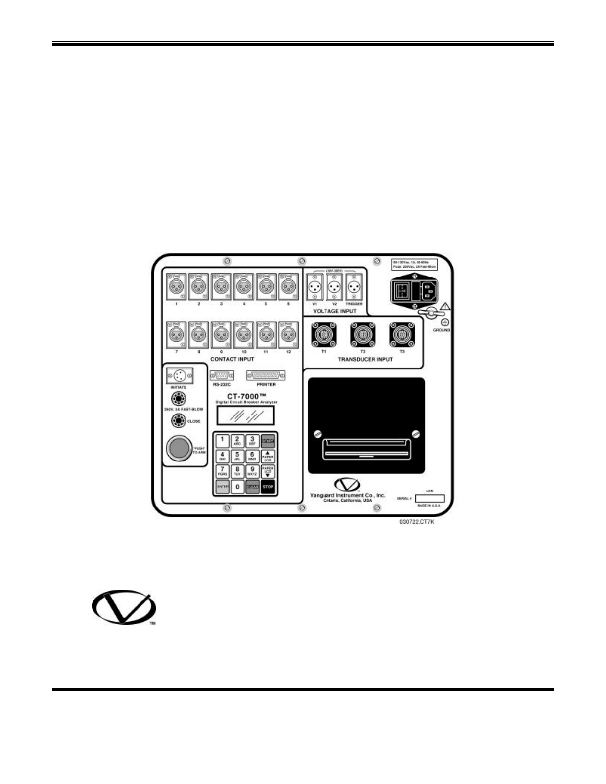
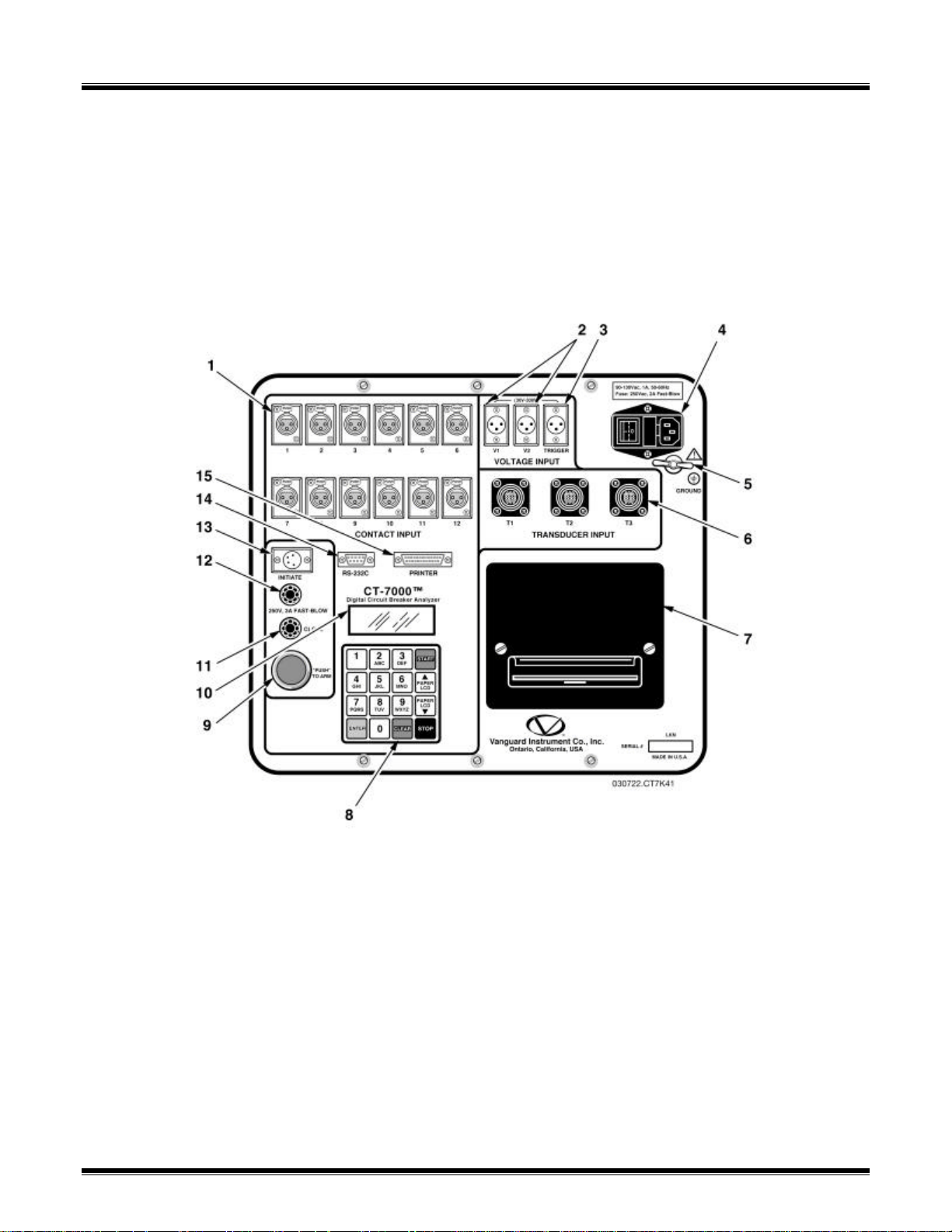
5.0 CT-7000 Controls and Display
Before using the CT-7000, users should become familiar with all of the controls and display
indications. The keypad and display are used to operate the CT-7000. Figure 1.0 represents the
control panel and the numbered lines pointing to each control and indicator refer to Table 1.0,
which describes the function of each control and indicator.
Figure 1.0 CT-7000 Control Panel
Page 14

CT-7000 Operating Instructions
Table 1.0 CT-7000 Controls and Displays
Fig. 1.0
Index no.
1
2
3
4
5
6
7
PANEL MARKING FUNCTIONAL DESCRIPTION
CONTACT INPUT
Female connectors for the contact channels.
(1 –12)
30-300V
V1 & V2
VOLTAGE INPUT
30-300V
TRIGGER
3-pin connectors. Each input is a voltage detector for
the timing voltages of the trip or close coil switching
during the active period. Voltage detection level ranges
from 30 to 300 Vdc or peak.
3-pin connector triggers timing functions. Voltage levels
ranging from 30 to 300 Vac, dc or peak.
VOLTAGE INPUT
120/240Vac, 2A, 50-60Hz
Fuse: 250Vac, 3A Fast-Blow
GROUND
T1, T2, T3
TRANSDUCER INPUT
(Printer; No panel marking)
3-wire power plug. 3 Ampere, AC fuses. The ON/OFF
switch is a 2-pole rocker.
Safety, ground terminal. 5/16-18 thread stud, with wing
nut.
16-pin connectors. Each input is a travel encoder input
used for contact, motion data.
Thermal printer. Microprocessor controlled printer that
uses specially treated, 4.5 inch wide paper.
8
9
10
11
12
13
14
15
1-9, 0, ENTER, START,
STOP, CLEAR,
PAPER LCD,
↑
PAPER LCD
↓
“PUSH” TO ARM
(Display; no panel marking)
CLOSE
250V, 5A FAST-BLOW
OPEN
250V, 5A FAST-BLOW
INITIATE
RS-232C
PRINTER
16 button keypad. The keys are momentary-contact,
pushbutton switches. Allows users to make menu
selections, enter alphanumeric data, adjust the LCD
contrast and reposition the printer paper.
Spring-loaded, pushbutton switch. Press and hold to
complete the Trip or Close circuits for breaker tests.
4-line by 20-character, backlit LCD. Displays menus,
options, prompts and test result data.
Close circuit fuse: 5 Ampere, 250V, Fast-Blow.
Open circuit fuse: 5 Ampere, 250V, Fast-Blow.
4-pin connector used for the switching circuit for
operating the circuit breaker under test.
9-pin connector for serial computer interface.
Parallel printer port.
Page 15

CT-7000 Operating Instructions
6.0 CT-7000 Analyzer Specifications
CONTACT TIMING Open, Close, Open-Close, Close-Open, and Open-Close-Open.
SIZE & WEIGHT 16d by 14w by 11h (inches), less than 32 pounds.
OPERATING POWER 2 Ampere, 90-120 Vac / 200-240 Vac 50/60 Hz.
TIMING WINDOW Selectable between: 1, 10, or 20 second.
RESOLUTION ±100 microseconds at 1 second duration.
±1.0 millisecond at 10 second duration.
±2.0 millisecond at 20 second duration.
DRY-CONTACT INPUT 3 or 6 or 12 contact channels. All contact inputs are grounded until testing
is started. Each contact detects main and insertion resistor contacts.
CONTACT RESISTANCE CLOSED: less than 20 Ohms.
OPEN: greater than 10,000 Ohms.
INSERTION RESISTANCE Ranges from 10 to 7,000 Ohms.
TRIGGER INPUT Open/Close: 30 to 300 Vdc, peak Vac.
VOLTAGE INPUTS 2 voltage inputs, sensitivity ranging from 1.0 to 300 Vdc, peak Vac.
Analog voltage recording ranges from 1.0 to 255 Vdc.
CURRENT-SENSOR INPUT 1 non-contact, hall-effect sensor ranging from 0.2 to 20 Amperes, DC to 5 kHz.
BREAKER INITIATE Initiate Open, Close, Open-Close, Close-Open, Open-Close-Open.
TRAVEL TRANSDUCER 3 travel-transducer channels. Linear motion from 0.0 to 60.0 inches (±0.01) inch.
INPUT Rotary ranges from 0 to 360o (± 0.36º).
BREAKER SLOW-CLOSE
TEST Measures the contact point distance.
STORAGE CAPABILITIES Store 99 Circuit Breaker Test Plans.
Store up to 100 timing records.
BREAKER ANALYSIS Windows 95, 98, 2000, NT, XP compatible.
SOFTWARE (included) The analysis software can be installed on a IBM-compatible computer for graphical
display, numerical reports and database utility for office use.
COMPUTER INTERFACE RS-232C Port.
DISPLAY Backlit LCD screen, 4-lines by 20-characters, sunlight viewable.
HARD-COPY PRINTOUT Contact travel waveforms and tabulated results printout on 4.5 inch thermal paper.
CARRYING CASE (optional) Hard shipping case for CT-7000 and cables.
Hard shipping case for Travel Transducers.
WARRANTY One year warranty on parts and labor. Post-warranty service contracts available.
Page 16

7.0 CT-7000 Special Features
7.1 CT-7000 Supplied Cables
ITEM DESCRIPTION QTY
1 GND Cable 1
2 Power Cord 1
3 Contact Cable 3 or 6 or 12
4 Contact Extension Cable 3 or 6 or 12
5 Transducer cable 1
6 Voltage & Trigger Leads 3
7 Voltage & Trigger Extension cables 3
8 Initiate Lead 1
9 Initiate Extension Cable 1
10 RS-232C Cable 1
CT-7000 Operating Instructions
Table 2.0 CT-7000 Cable set
Page 17

CT-7000 Operating Instructions
7.2 CT-7000 Operating Voltages
The CT-7000 operating voltage is selectable between 110/120 Vac, 50/60 Hz or 220/240
Vac, 50/60 Hz. Voltage selection is set by the JP1 connector on the Power Supply board and the
JP3 connector on the Initiate board of the CT-7000. The jumper settings for the connectors are
shown in Table 3.0.
Table 3.0 Voltage Selection Jumper Setting
VOLTAGE SELECTION CONNECTOR PIN
110-120 Vac Pin 1& 2, 3 & 4
220-240 Vac Pin 2 & 3
An initiate circuit relay with the corresponding operating voltage must also be installed in the
CT-7000 Initiate board.
NOTE
The factory sets the operating voltage.
7.3 CT-7000 Main Power Fuse
The CT-7000 uses an AC input module that contains the AC receptacle, power switch and
protective fuses. The 3 Ampere replacement fuses should be 20mm, 250Vac, fast-blow types.
NOTE
The OPEN and CLOSE initiate are 5 Ampere fuses that should be 3AG, 250Vac,
fast-blow types.
7.4 CT-7000 Printer and Printer Paper
The built-in, thermal printer uses 4.5 inch wide, thermal paper for printing test results. To
maintain the highest, quality printing and to avoid paper jamming, it is highly recommended that
the thermal paper be supplied by the factory. Additional paper can be ordered from either of the
two sources listed below:
Vanguard Instruments Co, Inc.
1710 Grevillea Court
Ontario, CA 91761
Tel: 909-923-9390
Fax: 909-923-9391
Part Number: TP-4 Paper
BG Instrument Co.
13607 E. Trent Avenue
Spokane, WA 99216
Tel: 509-893-9881
Fax: 509-893-9803
Part Number: TP-4 paper
Page 18

CT-7000 Operating Instructions
7.5 CT-7000 Printer Paper Control
To advance the paper from the printer, press and release the “↑ PAPER LCD” button. To
retract the thermal paper from the printer, press and release the “↓ PAPER LCD” button.
7.6 Replacing CT-7000 Thermal Paper
The roll of thermal paper resides inside a pocket underneath the printer cover. To replace the
paper, follow the steps below:
n Remove the printer cover.
n Remove the leftover thermal paper roll from the paper holder.
n Unroll the new thermal paper.
n Feed the thermal paper into the slot between the paper pocket and the rubber
roller. The printer will au tomatically pull the paper under the thermal head.
n Place the paper roll into the paper holder.
n Lift the thermal head and align the thermal paper if necessary.
n Replace the printer cover back.
NOTE
The thermal paper will show a red stripe in the margin to indicate that the roll is
about to run out of paper.
7.7 CT-7000 LCD Contrast Control
To darken the LCD screen, press and hold the “↑ PAPER LCD” button, while to decrease the
contrast of the LCD screen, press and hold the “↓ PAPER LCD” until the desired contrast is
reached.
Page 19
CT-7000 Operating Instructions
8.0 Test Hook-up Connections
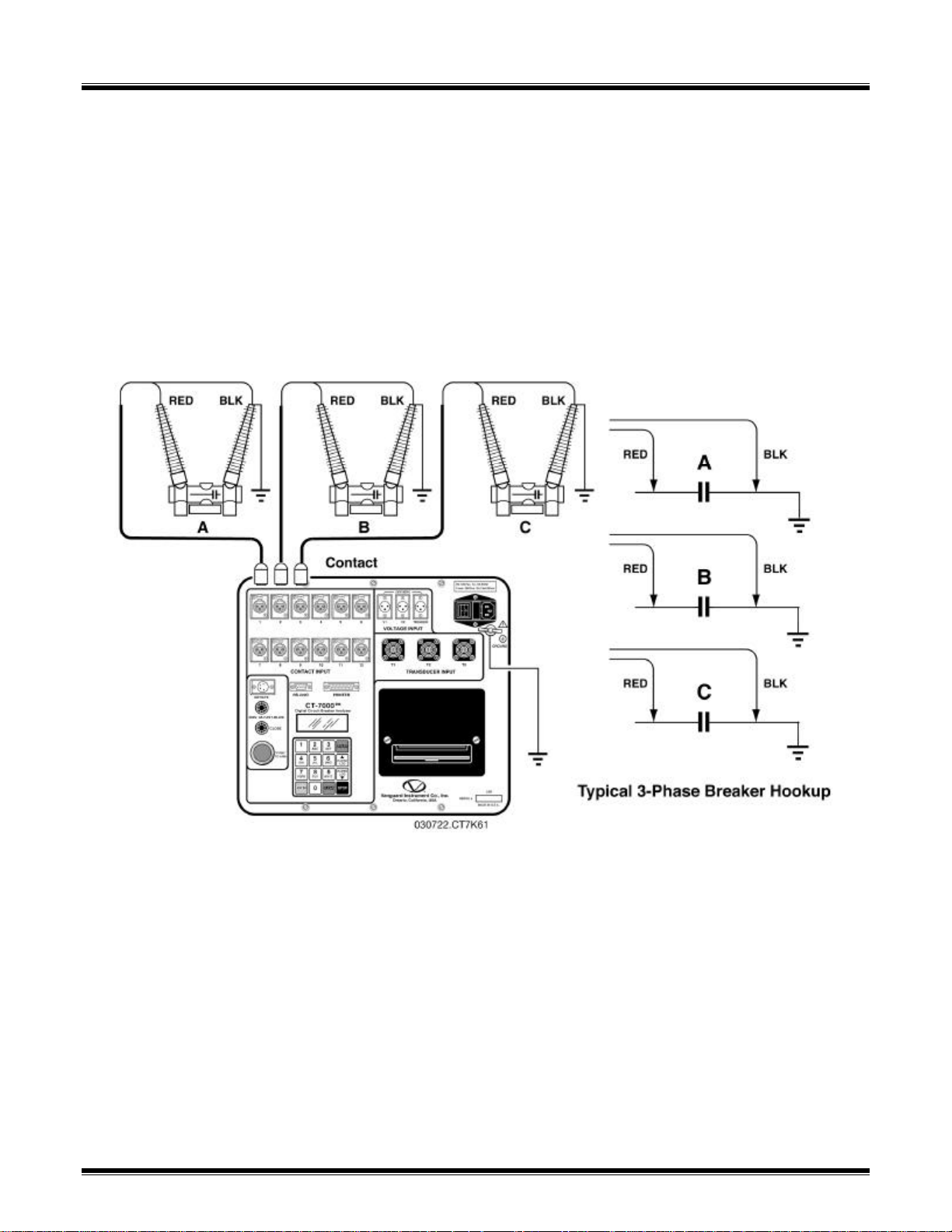
8.1 Contact Cable Hookup
A typical, contact cable connection to a circuit breaker is shown in Figure 2.0. Red clips are
connected to phase A, B and C of the breaker’s bushings. The black clips are connected on the
grounded or common, side of the bushings. For circuit breakers with series contacts, connect the
contact cables as shown in Figure 3.0.
NOTE
It is advisable to ground one side of the contacts for most testing purposes. If a breaker
is floating or ungrounded, ensure that the contact channel inputs are protected against
static discharge.
Figure 2.0 Contact Cable Connection
Page 20
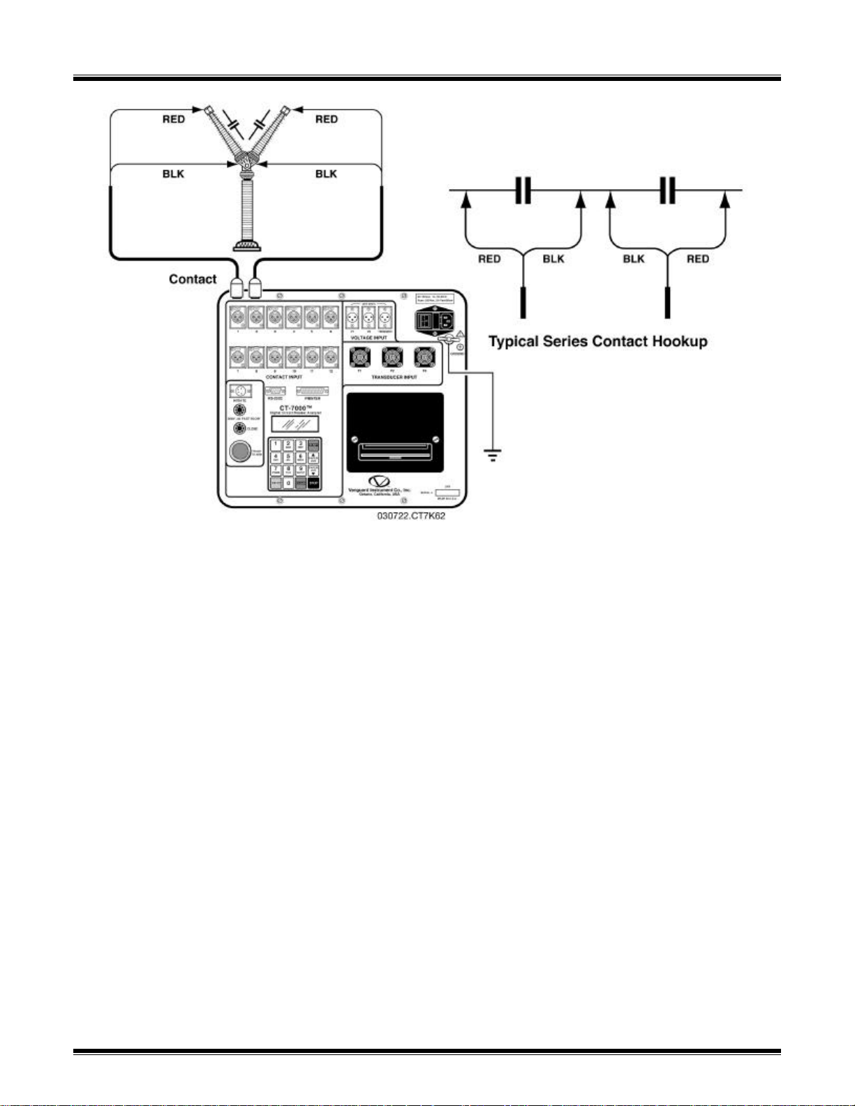
CT-7000 Operating Instructions
Figure 3.0 Series Contact Cable Connection
Page 21
CT-7000 Operating Instructions
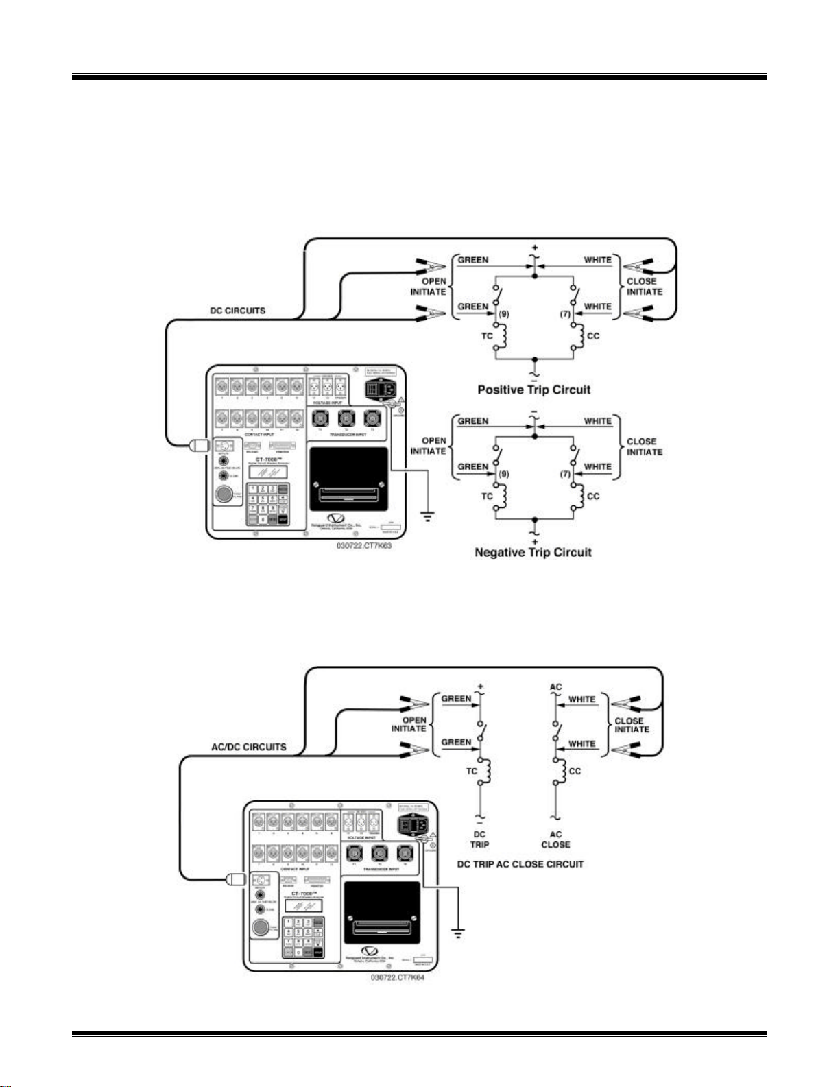
8.2 Initiate Cable Hookup
The CT-7000 will trip or close breakers through a solid-state device, which will operate on any
AC or DC control voltage ranging from 10 to 300 Volts. Both the trip and close circuits are
protected by 5 Ampere fuses.
A typical DC trip and DC close, control circuit test hookup is shown in Figure 4.0.
A typical DC trip and AC close, control circuit test hookup is shown in Figure 5.0.
Figure 4.0 DC Trip and DC Close, Initiate Circuit Cable Hook-Up
Figure 5.0 DC Trip and AC Close, Initiate Circuit Cable Hook-Up
Page 22
CT-7000 Operating Instructions
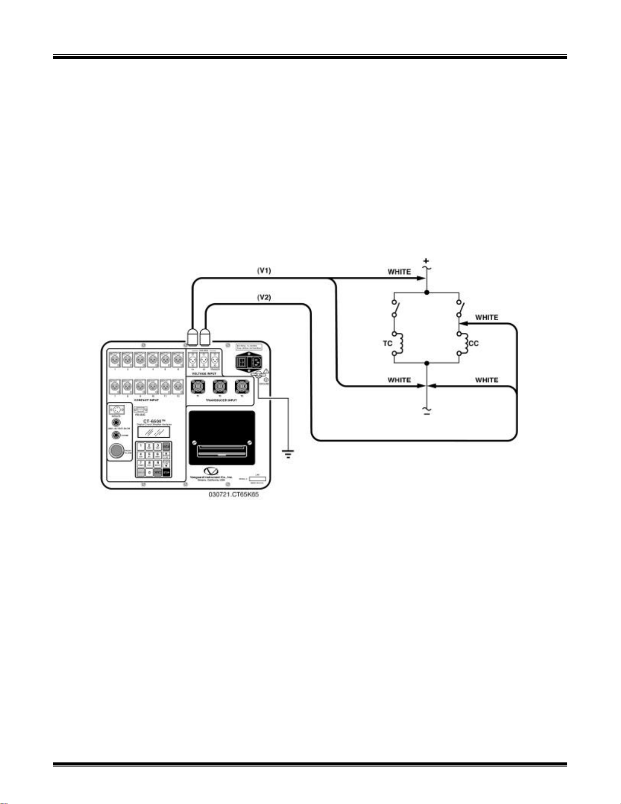
8.3 Analog Voltage Monitor Hookup
The analog, voltage input, “V1” permits the user to monitor a breaker's DC control voltage
during an operation. The analog, voltage input will record the nominal DC voltage at no load and
the minimum DC voltage while the Trip or Close coil is energized.
The nominal and minimal voltage readings will be printed on a tabulated report. Analog
waveforms will also be plotted in a graphical format. Thus, the user is able to see the breaker's
DC control voltage "dip" under load conditions. Problems, such as a poor connection or an
excessive voltage drop, during operation can be easily detected.
A typical voltage monitoring hook up scheme is shown on Figure 6.0.
NOTE
The maximum voltage that can be recorded is set at 255 Vdc.
Figure 6.0 Voltage Monitoring Cable Hook-Up
8.4 Digital Voltage Monitor Hookup
The digital, voltage input channel, “V2” permits the user to monitor the voltage status as “ON”
or “OFF” states. The voltage “ON” or “OFF” states will be plotted on the graphical report. A typical
hook up is shown in Figure 6.0.
Page 23
CT-7000 Operating Instructions
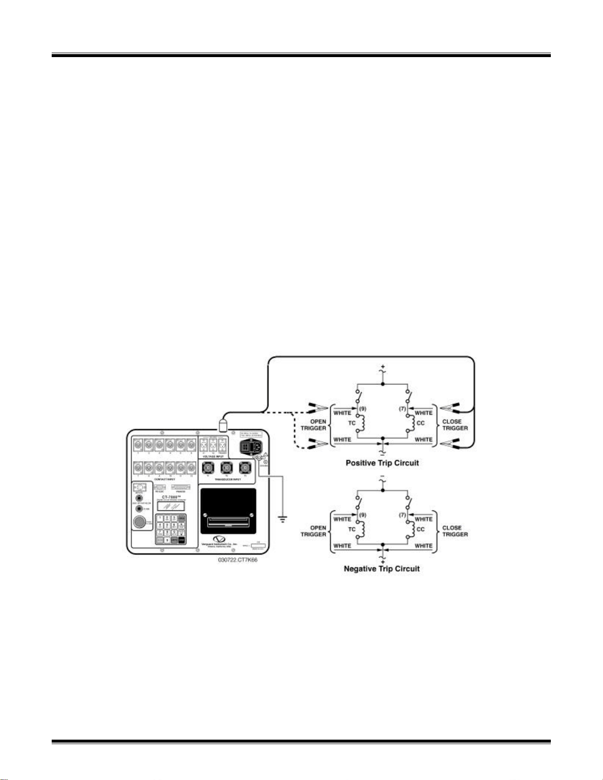
8.5 External Trigger Input
The External Trigger Mode enables the user to start recording data when the CT-7000 senses
a voltage. A typical application for the External Trigger Mode is to time a circuit breaker in a close
operation and to start timing only when the close coil is energized, thus bypassing the 52X relay
delay time.
Since the 52X relay carries the close coil current, the user will need to connect the CT-7000’s
initiate cable to the close terminal shown in Figure 4.0. The CT-7000 will energize the 52X relay
to start the close operation, which will then start the timing when the CT-7000 senses the voltage
across the closing coil. See Figure 7.0 for a typical test hookup. Another application for external
trigger is to start timing the breaker when the user trips or closes the breaker remotely.
NOTE
Minimum trigger voltage is set for 30 Vac/dc. Maximum, continuous voltage is limited at
300 Vac/dc. Different trigger voltages can be set at the factory, based upon specific
requests.
The CT-7000 will start looking for the external trigger voltage when the message,
“AWAITING TRIGGER…” is shown on the LCD screen. The external trigger voltage
needs to be sensed by the CT-7000 within 30 seconds after the initiate sequence has
begun. The CT-7000 will return to the main menu if no voltage is sensed.
Figure 7.0 External Trigger Cable Hook-Up
Page 24

CT-7000 Operating Instructions
8.6 Transducer Connection
A typical transducer connection is shown on Figure 8.0. See Appendix I for more transducer
connections.
Figure 8.0 Transducer Connection
Page 25
CT-7000 Operating Instructions
HOOKUP CT-7000
APPLY POWER
TIMER BREAKER
GET RESULTS
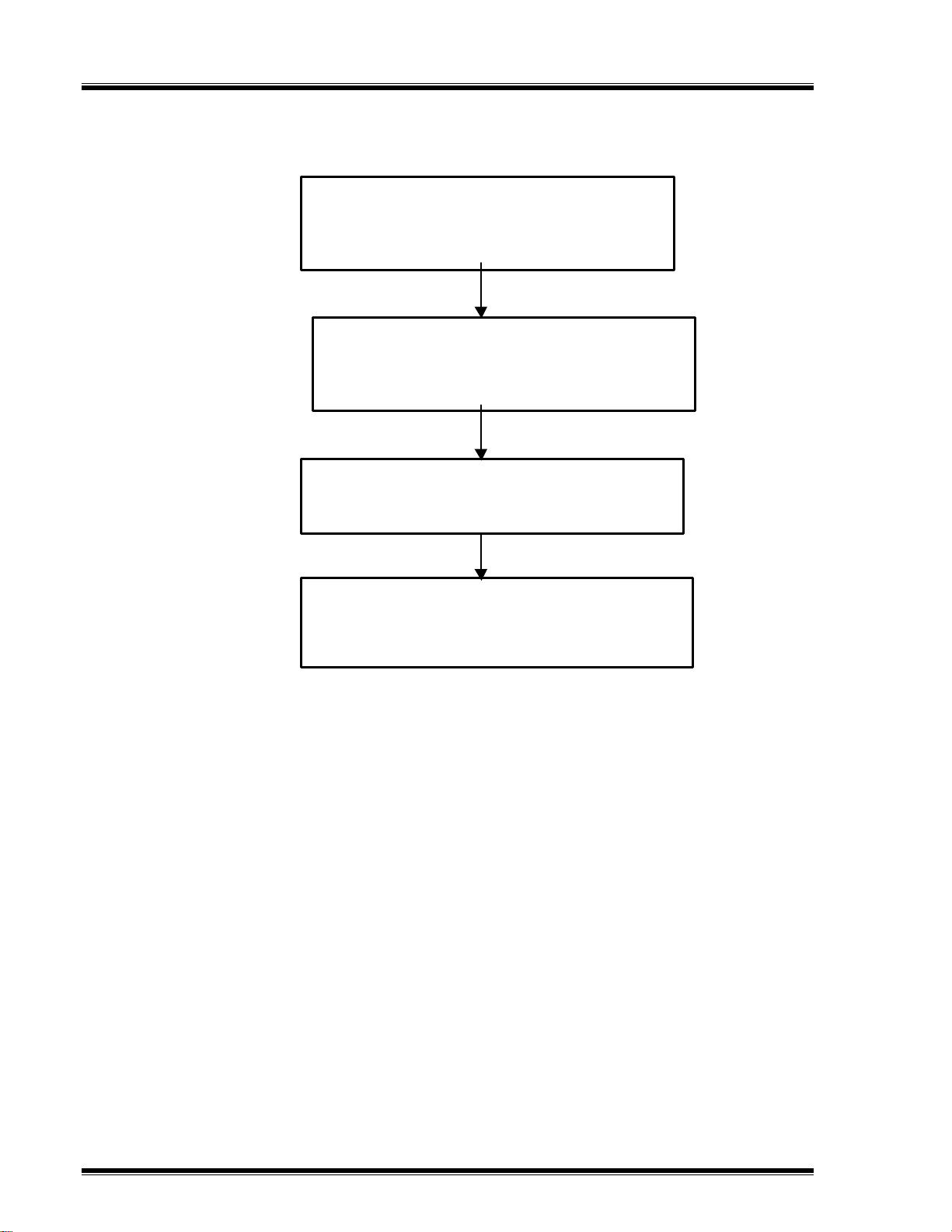
9.0 Operating Procedures
The main steps to time a circuit breaker are listed in Figure 9.0.
.
1. GROUND THE CT-7000 (See NOTE)
2. CONNECT CT-7000 CABLES TO BREAKER
3. INSTALL TRANSDUCER WITH CABLE
1. TURN THE CT-7000 ON
2. PERFORM SELF TESTS: HOOK-UP TEST,
CABLE TEST, IF NECESSARY
1. SELECT THE CT-7000 TEST
2. OPERATE THE BREAKER
1. READ OR PRINT THE TABULATED RESULTS
2. PRINT THE GRAPHICAL RESULTS
3. SAVE THE TIMING SHOT
Figure 9.0 CT-7000 Operating Steps
NOTE
To reduce the possibility of damaging the CT-7000 contact channels due to static
discharge in the high voltage substations, it is recommend to ground one side of
the breaker’s bushings.
Page 26

CT-7000 Operating Instructions
9.1 Timing a Circuit Breaker
The CT-7000 will initiate the breaker operation and do a timing test on the following
operations:
n
OPEN
n
CLOSE
n
OPEN-CLOSE
n
CLOSE-OPEN
n
OPEN-CLOSE-OPEN
NOTE
1. The CT-7000 can start the OPEN-CLOSE operations without a delay or by using a
programmable delay between the OPEN and CLOSE commands.
2. The CLOSE-OPEN can be started by the CT-7000, using several options.
n
Contact #1 Close
The CT-7000 can initiate a CLOSE command and then an OPEN command after
detecting the breaker’s contact was closed. The CT-7000 detects that the
breaker’s contact was closed through contact channel #1. The selection is
recommended for the CLOSE-OPEN operation since it truly represents when the
circuit breaker closed and then opened.
n
Set DELAY
The CT-7000 can initiate a CLOSE command and then an OPEN command after
a programmable delay that can be set in milliseconds.
n
No DELAY
The CT-7000 can initiate a CLOSE command and then an OPEN command
without any delay. Since the circuit breaker is in the open state, the circuit
breaker’s 52B contact allows the close coil to be energized, which can start the
close command. When the circuit breaker is making the transition from an open
state to a close state, the 52A contact will close allowing the breaker to initiate the
open command.
3. The OPEN-CLOSE-OPEN operations can be initiated by the CT-7000, by using a
programmable delay between each of the operations, where the delays can be set
between the OPEN to CLOSE and between the CLOSE to OPEN commands.
Page 27

CT-7000 Operating Instructions
9.1.1 Timing an OPEN Operation With No Insertion Resistors
Table 4.0 Open Operation With No Insertion Resistors
STEP
1 READY TIMER FOR BREAKER OPERATION. PRESS #1 KEY. INSERTION RESISTOR?
2 SELECT NO INSERTION RESISTOR. PRESS #1 KEY. TIMING WINDOWS:
3 SELECT 1-SECOND TIMING WINDOW. PRESS #1 KEY. TRIGGER MODE:
4 SELECT INTERNAL TRIGGER. PRESS #1 KEY. TIMING MODE:
5 SELECT OPEN OPERATION. PRESS #1 KEY. OPEN TIMING
6 INITIATE OPEN COMMAND. HOLD THE "ARM"
OPERATION
SWITCH AND
PRESS THE "START"
KEY.
ACTION DISPLAY
1.NO
2.YES
1.WINDOW = 1 SEC
2.WINDOW = 10 SEC
3. WINDOW = 20 SEC
1. Internal Trigger
2. External Trigger
1. OPEN 2. CLOSE
3. O-C 4. C-O
5. O-C-O
Hold "ARM" Switch,
Then "START".
"STOP" to ABORT
TEST IN PROGRESS
Hold "ARM" Until
Test complete.
(Up to 15 seconds)
7 OBSERVE BREAKER OPERATED.
ANALYZER IS READY TO OUTPUT RESULTS.
NONE. 1.TIME BREAKER
2.GET RESULT
3.SET-UP
4.DIAGNOSTIC
NOTE
One-second timing windows are used for breaker timing. The 10 and 20 second
timing windows are used for circuit-switcher timing.
Page 28

CT-7000 Operating Instructions
9.1.2 Timing an OPEN Operation With Insertion Resistors
The CT-7000 can time breakers with insertion resistors. The insertion resistor can
range from 10 to 7,000 Ohms. Any insertion resistor more than 7,000 Ohms is detected as
an open circuit. The timing window results will show the main contact time and the insertion
resistor contact time. Graphic reports will show the main contact and the resistor contact
activities on each of the channels.
Table 5.0 Open Operation With Insertion Resistor
STEP OPERATION ACTION DISPLAY
1 READY TIMER FOR BREAKER OPERATION. PRESS #1 KEY. INSERTION RESISTOR?
1.NO
2.YES
2 SELECT INSERTION RESISTOR. PRESS #2 KEY. RESISTOR VALUE:
1.LESS THAN 1000 OHM
2.1000 to 2000 OHM
3.MORE THAN 2000 OHM
3 SELECT LESS THAN 1000 OHM RESISTOR
RANGE.
4 SELECT 1-SECOND WINDOW. PRESS #1 KEY. TRIGGER MODE:
5 SELECT INTERNAL TRIGGER. PRESS #1 KEY. TIMING MODE:
6 SELECT OPEN OPERATION. PRESS #1 KEY. OPEN TIMING
7 INITIATE OPEN COMMAND. HOLD THE "ARM"
8 ANALYZER IS READY TO OUTPUT RESULTS. NONE. 1.TIME BREAKER
PRESS #1 KEY. TIMING WINDOWS:
1.WINDOW = 1 SEC
2.WINDOW = 10 SEC
3.WINDOW = 20 SEC
1. Internal Trigger
2. External Trigger
1. OPEN 2. CLOSE
3. O-C 4. C-O
5. O-C-O
Hold "ARM" Switch,
Then "START".
"STOP" to ABORT
TEST IN PROGRESS
SWITCH AND
PRESS THE "START" KEY.
Hold "ARM" Until
Test complete.
(Up to 15 seconds)
2.GET RESULT
3.SET-UP
4.DIAGNOSTIC
NOTE
The user can set the CT-7000 to print tabulated and graphical reports automatically
after it completes a test. See Paragraph 9.21 for the automatic print setting.
Page 29

CT-7000 Operating Instructions
9.1.3 Timing CLOSE-OPEN Operation Using Contact Channel #1
The CLOSE-OPEN operation of the breaker simulates a condition where a breaker is
closed on a fault. There are 3 choices for the user to setup the CLOSE-OPEN operation:
1. Contact #1 CLOSE
Open operation is initiated after contact channel # 1 is closed. Refer to
Table 6.0 on the next page.
2. Set DELAY
The user can set a delay from 10 to 500 ms between a CLOSE command
to the OPEN command.
3. No DELAY
Both the CLOSE and OPEN commands are initiated by the CT-7000
simultaneously. The OPEN coil is energized when the Open auxiliary switch
makes.
NOTE
If the Contact #1 CLOSE choice is used, the CT-7000 will first initiate a CLOSE
command and then send an OPEN command only when it detects that the main
contact #1 is closed. The mode truly simulates when the breaker is closing on a fault
condition in the field.
Page 30

CT-7000 Operating Instructions
Table 6.0 Close-Open Operation Using Contact Channel #1
STEP OPERATION ACTION DISPLAY
1 READY TIMER FOR BREAKER OPERATION. PRESS #1 KEY. INSERTION RESISTOR?
1.NO
2.YES
2 SELECT NO INSERTION RESISTOR. PRESS #1 KEY. TIMING WINDOWS:
1.WINDOW = 1 SEC
2.WINDOW = 10 SEC
3.WINDOW = 20 SEC
3 SELECT 1-SECOND WINDOW. PRESS #1 KEY. TRIGGER MODE:
1.Internal Trigger
2.External Trigger
4 SELECT INTERNAL TRIGGER. PRESS #1 KEY. TIMING MODE:
1. OPEN 2. CLOSE
3. O-C 4. C-O
5. O-C-O
5 SELECT CLOSE-OPEN OPERATION. PRESS #4 KEY. C-O Second Trigger:
1. Contact #1 CLOSE
2. Set DELAY
3. No DELAY
6 SELECT CONTACT #1 CLOSE. PRESS #1 KEY. CLOSE-OPEN TIMING
Hold "ARM" Switch,
Then "START".
"STOP" to ABORT
7 INITIATE OPEN COMMAND. HOLD THE "ARM"
SWITCH AND
PRESS THE "START"
KEY.
8 ANALYZER IS READY TO OUTPUT RESULTS. NONE. 1.TIME BREAKER
TEST IN PROGRESS
Hold "ARM" Until
Test complete.
(Up to 15 seconds)
2.GET RESULT
3.SET-UP
4.DIAGNOSTIC
NOTE
1. Users can program a delay from 10 to 500 ms between the CLOSE and
OPEN commands. When a delay is used in the operation, it may not
represent a true breaker operating condition.
2. Users can also program in no delay for the operation in which case, the
CLOSE and OPEN commands are initiated at the same time by the CT-
7000.
Page 31

CT-7000 Operating Instructions
9.1.4 Timing OPEN-CLOSE-OPEN Operation
The OPEN-CLOSE-OPEN operation requires the user to enter two time-delays
between the circuit breaker operations. The time delays are in millisecond intervals. The
first delay is from the first OPEN command to the CLOSE command. The second delay is
from the CLOSE command to the second OPEN command. Refer to Table 7.0 for setting
up the OPEN-CLOSE-OPEN operation.
Table 7.0 Open-Close-Open Operation Using Delay
STEP OPERATION ACTION DISPLAY
1 READY TIMER FOR BREAKER OPERATION. PRESS #1 KEY. INSERTION RESISTOR?
1.NO
2.YES
2 SELECT NO INSERTION RESISTOR. PRESS #1 KEY. TIMING WINDOWS:
1.WINDOW = 1 SEC
2.WINDOW = 10 SEC
3.WINDOW = 20 SEC
3 SELECT 1-SECOND WINDOW. PRESS #1 KEY. TRIGGER MODE:
1.Internal Trigger
2.External Trigger
4 SELECT INTERNAL TRIGGER. PRESS #1 KEY. TIMING MODE:
1. OPEN 2. CLOSE
3. O-C 4. C-O
5. O-C-O
5 SELECT OPEN-CLOSE-OPEN OPERATION. PRESS #5 KEY. O-C Delay in mS:
(10 – 350)
mSec
ENTER when done
6 SELECT DELAY BETWEEN OPEN-CLOSE
OPERATION.
7 SELECT DELAY BETWEEN CLOSE-OPEN
OPERATION.
8 INITIATE O-C-O COMMAND. HOLD THE "ARM"
9 ANALYZER IS READY TO OUTPUT RESULTS. NONE. 1.TIME BREAKER
ENTER DELAY USING 09 KEYS, PRESS THE
“ENTER” KEY TO
CONFIRM.
ENTER DELAY USING 09 KEYS, PRESS THE
“ENTER” KEY TO
CONFIRM.
SWITCH AND
PRESS THE "START"
KEY.
C-O Delay in mS:
(10 – 350)
mSec
ENTER when done
OPEN-CLOSE-OPEN TIMING
Hold "ARM" Switch,
Then "START".
"STOP" to ABORT
TEST IN PROGRESS
Hold "ARM" Until
Test complete.
(Up to 15 seconds)
2.GET RESULT
3.SET-UP
4.DIAGNOSTIC
Page 32

CT-7000 Operating Instructions
9.2 Get Tabulated Timing Results Using the Thermal Printer
The circuit breaker timing results can be printed on the thermal printer by using the steps listed in
Table 8.0.
A typical circuit breaker timing result printed on thermal printer is shown in Figure 10.0.
A typical circuit breaker timing result printed on ink-jet printer is shown in Figure 11.0.
Table 8.0 Get Tabulated Results
STEP OPERATION ACTION DISPLAY
1 GET TIMING RESULTS. PRESS #2 KEY. 1.PRINT TEST RESULTS
2.PLOT FULL CHART
3.PLOT EXPANSION
4.PLOT 0-200 MS
2 PRINT TABULATED RESULTS. PRESS #1 KEY. SELECT PRINTER
1. INTERNAL THERMAL
2. EXTERNAL INK JET
3. DISPLAY RESULTS
3 OUTPUT TABULATED RESULTS ON
THERMAL PRINTER.
PRESS #1 KEY. BUSY PRINTING
Page 33

CT-7000 Operating Instructions
1611456789109131415171212
3
Figure 10.0 Typical Tabulated Printout of an Open Operation From the Thermal Printer
Page 34

CT-7000 Operating Instructions
9.2.1 Tabulated Results Interpretation
1. Timing Record is time and date stamped by the CT-7000.
2. Timing record header information (Company, Substation name, Circuit, etc) is also saved
with test record.
3. Timing test type (OPEN, CLOSE, O-C, C-O, O-C-O) is identified. An OPEN timing shot is
shown in figure 10.0.
4. Contact channel #1 time is shown in both milliseconds and cycles. From Figure 10.0,
contact channel #1 time was 34.20 ms or 2.05 cycles.
5. Contact channel #1 bounce duration was 0.20 ms.
6. Contact channel #1 wipe was measured as 0.72 inches.
7. The slowest contact and fastest contact differential time is shown as contact delta, 3.00 ms.
8. Breaker contact stroke was measured as 7.02 inches.
9. Contact velocity calculation was 8.55 feet per second.
10. Contact over-travel distance was measured as 0.01 inches.
11. Contact bounce-back distance was measured 0.06 inches.
12. Contact velocity calculation was from the two analysis points:
Analysis point # 1 was 1.00 inch from the fully closed position.
Analysis point # 2 was 5.00 inches from the fully closed position.
13. The DC power supply was monitored during the test. The nominal voltage was 47 Volts
and the minimum voltage was 47 Volts.
14. Initiate current was 5.7 Amperes.
15. Timing shot duration was one second.
16. Trigger mode was internal therefore the timing window starts at the same time when the
CT-7000 energized the circuit breaker.
17. There was no insertion resistor in the test, thus no insertion resistor time was measured.
Page 35

CT-7000 Operating Instructions
Figure 11.0 Typical Tabulated Printout of an Open Operation From Ink Jet Printer
Page 36

CT-7000 Operating Instructions
9.3 Get Graphic Timing Results Using the Thermal Printer
Selecting the “PLOT FULL CHART” command will plot the timing chart as follows:
Timing chart from 0 to 1000 ms with one second window and 50 ms time markers.
•
Timing chart from 0 to 10 seconds with 10 second window and 500 ms time markers.
•
Timing chart from 0 to 20 seconds with 20 second window and one second time markers.
•
Table 9.0 Plot Chart and Tabulated Report
STEP OPERATION ACTION DISPLAY
1 GET TIMING RESULTS. PRESS #2 KEY. 1. PRINT TEST RESULTS
2. PLOT FULL CHART
3. PLOT EXPANSION
4. PLOT 0-200 MS
2 PLOT FULL CHART. PRESS #2 KEY. SELECT PRINTER
1. INTERNAL THERMAL
2. EXTERNAL INK JET
3 SELECT THERMAL PRINTER. PRESS #1 KEY. PLEASE WAIT
PLOTTING GRAPH
4 RETURN TO MAIN MENU AFTER PRINT
CHART.
NO ACTION. 1. TIME BRKR
2. GET RSLT
3. SET UP
4. DIAGNOSTIC
NOTE
1. Plot Expansion, which is Selection #3, in Step 1, allows the user to expand the graphic
results in 100 ms increments.
2. Selecting “PLOT 0-200 MS” will automatically plot the timing chart from 0 to 200
milliseconds in the expansion mode with 10 ms timing markers, which can be seen in
Figure 14.0.
3. Graphical result interpretations are shown in Figures 16.0, 17.0 and 18.0.
Page 37

CT-7000 Operating Instructions
Contact Trace
Travel Trace
Initiate Current
V1
Analog Voltage Channel
Digital Voltage Channel V2
Figure 12.0 Typical Graphic Result From the Thermal Printer
Page 38

CT-7000 Operating Instructions
Figure 13.0 Typical Graphic Printout From the Ink Jet Printer
Page 39

CT-7000 Operating Instructions
Analysis Point #1
Analysis Point #2
Figure 14.0 Expansion Graph From 0 to 200ms From the Thermal Printer
NOTE
Analysis point # 1 and point #2 are shown on chart.
Page 40

CT-7000 Operating Instructions
Figure 15.0 Expansion Graph From 0 to 200ms From Ink Jet Printer
Page 41

CT-7000 Operating Instructions
Figure 16.0 Graphical Interpretation of an Open Timing Shot
Figure 17.0 Graphical Interpretation of a Close Timing Shot
Page 42

CT-7000 Operating Instructions
Figure 18.0 Graphical Interpretations of an Open-Close and a Close-Open Timing Shot
Page 43

CT-7000 Operating Instructions
9.4 Save Timing Shots in the EEPROM
Use the steps in Table 10.0 to save a timing shot in the FLASH EEPROM.
Table 10.0 Save Timing Shot In EEPROM
STEP OPERATION ACTION DISPLAY
1 SELECT SETUP MENU. PRESS #3 KEY. 1. ANALYSIS POINTS
2. MEASUREMENT UNITS
3. SAVE / RESTORE
4. NEXT PAGE
2 SELECT SAVE MENU. PRESS #3 KEY. 1. SAVE SHOT
2. RECALL SHOT
3. SHOT DIRECTORY
4. ERASE SHOT
3 SELECT SAVE SHOT. PRESS #1 KEY. SAVE SHOT # 002
TEST: CLOSE
DATE: 04/23/03 12:36
"ENTER" TO CONFIRM
4 CONFIRM SAVING SHOT. PRESS THE "ENTER"
KEY.
5 OBSERVE SHOT BEING SAVED. NONE. SHOT SAVE
6 RETURN TO MAIN MENU. PRESS ANY KEY. 1. TIME BRKR
SAVE IN PROCESS
PLEASE WAIT
2. GET RSLT
3. SET UP
4. DIAGNOSTIC
NOTE
Timing shot storage capability varies, depending upon the size of the shots.
The CT-7000 will assign an identification number for each of the shots stored in the
EEPROM.
Page 44

CT-7000 Operating Instructions
9.5 Printing Timing Shot Directory Stored in the EEPROM
The user can obtain a timing-shot directory that was stored in the CT-7000’s FLASH
EEPROM by using the following steps in Table 11.0.
Table 11.0 Print Timing Shot Directory
STEP OPERATION ACTION DISPLAY
1 SELECT SETUP MENU. PRESS #3 KEY. 1. ANALYSIS POINT
2. MEASUREMENT UNITS
3. SAVE / RESTORE
4. NEXT PAGE
2 SELECT SAVE/RESTORE MENU. PRESS #3 KEY. 1. SAVE SHOT
2. RESTORE SHOT
3. SHOT DIRECTORY
4. ERASE SHOT
3 SELECT SHORT DIRECTORY. PRESS # 3 KEY. 1. SHORT DIRECTORY
2. FULL DIRECTORY
"STOP" TO QUIT
4 SELECT SHORT DIRECTORY. PRESS #1 KEY. PRINTING ABBREVIATED
DIRECTORY
“STOP” TO QUIT
5 RETURN TO MAIN MENU. NO ACTION. 1. TIME BRKR
2. GET RSLT
3. SET UP
4. DIAGNOSTIC
NOTE
1. If the "Short Directory" was selected, the CT-7000 will print out the shot
identifications of the last ten timing shots stored in the EEPROM.
2. If the "Full Directory" was selected, the CT-7000 will print out the shot
identifications of all the timing shots stored in the EEPROM.
3. A typical shot directory printout is shown on next page, in Figure 19.0.
Page 45

CT-7000 Operating Instructions
Figure 19.0 Printout of the Timing Shot Directory From the Thermal Printer
Page 46

CT-7000 Operating Instructions
9.6 Recalling a Timing Shot
The following steps in Table 12.0 are used to recall a timing shot stored in the EEPROM to the
working memory. Once a timing shot is recalled, the user can ask for a printout of the test results
from the thermal printer.
Table 12.0 Recalling a Timing Shot
STEP OPERATION ACTION DISPLAY
1 SELECT SETUP MENU. PRESS #3 KEY. 1. ANALYSIS POINT
2. MEASUREMENT UNITS
3. SAVE / RESTORE
4. NEXT PAGE
2 SELECT SAVE/RESTORE SHOT. PRESS # 3 KEY. 1. SAVE SHOT
2. RESTORE SHOT
3. SHOT DIRECTORY
4. ERASE SHOT
3 SELECT RESTORE SHOT. PRESS #2 KEY. ENTER SHOT NUMBER
4 ENTER SHOT NUMBER “1” TO BE
RESTORED.
5 CONFIRM SHOT TO BE RESTORED. PRESS THE "ENTER"
6 CONFIRM TEST RESTORED. NONE. RESTORE COMPLETE
7 RETURN TO MAIN MENU. PRESS ANY KEY. 1. TIME BRKR
PRESS KEYS 0-9
FOR SHOT ID THEN
PRESS THE "ENTER"
KEY.
KEY.
TO BE RESTORED
XXXX
"ENTER" TO CONFIRM
ENTER SHOT NUMBER
TO BE RESTORED
0001
"ENTER" TO CONFIRM
RESTORING SHOT # 0001
TEST: OPEN
DATE: 03\12\03 09:12
"ENTER" TO CONFIRM
2. GET RSLT
3. SET UP
4. DIAGNOSTICS
Page 47

CT-7000 Operating Instructions
9.7 Deleting a Timing Shot
Users can delete a specific timing shot or all of the timing shots from the CT-7000’s EEPROM
by using the steps described in Table 13.0.
Table 13.0 Deleting a Timing Shot
STEP OPERATION ACTION DISPLAY
1 SELECT SET UP MENU. PRESS # 3 KEY. 1. ANALYSIS POINTS
2. MEASUREMENT UNITS
3. SAVE / RESTORE
4. NEXT PAGE
2 SELECT SAVE / RESTORE MENU. PRESS # 3 KEY. 1. SAVE SHOT
2. RESTORE SHOT
3. SHOT DIRECTORY
4. ERASE SHOT
3 SELECT ERASE SHOT. PRESS # 4 KEY. 1. ERASE SHOT
2. ERASE ALL SHOTS!
4 SELECT ERASE SHOT. PRESS # 1 KEY. ENTER SHOT NUMBER
TO BE ERASED
XXXX
"ENTER" TO CONFIRM
5 ENTER SHOT NUMBER “1” TO BE
ERASED.
6 CONFIRM TO ERASE SHOT. PRESS THE "ENTER"
7 WAIT FOR SHOT BEING ERASED. NO ACTION. ERASE COMPLETE
8 RETURN TO MAIN MENU. PRESS ANY KEY. 1. TIME BRKR
PRESS KEYS 0-9 TO
SELECT SHOT
NUMBER, PRESS
THE "ENTER" KEY
TO CONFIRM.
KEY.
ERASE SHOT # 0001
TEST: OPEN
DATE: 03\12\03 09:12
"ENTER" TO CONFIRM
ERASE IN PROCESS
PLEASE WAIT
2. GET RSLT
3. SET UP
4. DIAGNOSTIC
Page 48

CT-7000 Operating Instructions
9.8 Shot Description
The CT-7000 has the capability for users to enter the breaker and other identification
information. The data usually consists of the names of the company, station, circuit and
manufacturer. Other information could be the breaker's model, serial number and the operator's
name. The identification data will print out on the header section of the tabulated report.
If the user saves the timing shot, the identification data will also be saved with the timing shot,
along with the time and date.
The user can input letters of the alphabet by utilizing the alphanumeric keys. To select the letter
"A," the user will need to press key numbered “2,” twice. To select the letter "C," the user will need
to press the key numbered “2,” four times and so on.
To move the cursor forward, press the “UP ARROW” key. To move the cursor backwards, use
the “DOWN ARROW” key. Use the “CLEAR” key to enter a space.
Table 14.0 Entering Shot Identification Header
STEP OPERATION ACTION DISPLAY
1 SELECT SET UP MENU. PRESS #3 KEY. 1. ANALYSIS POINTS
2. MEASUREMENT UNIT
3. SAVE / RESTORE
4. NEXT PAGE
2 SELECT NEXT PAGE. PRESS # 4 KEY. 1. SHOT DESCRIPTION
2. NUMBER OF CHANNELS
3. COMPUTER IF
4. SET CLOCK
3 SELECT SHOT DESCRIPTION. PRESS # 1 KEY. ENTER COMPANY NAME
XXXXXX
"ENTER" TO CONFIRM
4 ENTER COMPANY NAME. PRESS KEYS 0-9
AND
PRESS THE "ENTER"
KEY TO CONFIRM.
5 ENTER STATION NAME. PRESS KEYS 0-9
AND
PRESS THE "ENTER"
KEY TO CONFIRM.
6 ENTER CIRCUIT NAME. PRESS KEYS 0-9
AND
PRESS THE "ENTER"
KEY TO CONFIRM.
7 ENTER MANUFACTURER NAME. PRESS KEYS 0-9
AND
PRESS THE "ENTER"
KEY TO CONFIRM.
ENTER STATION NAME
XXXXXX
"ENTER" TO CONFIRM
ENTER CIRCUIT NAME
XXXXXX
"ENTER" TO CONFIRM
ENTER MANUFACTURER NAME
XXXXXX
"ENTER" TO CONFIRM
ENTER BREAKER MODEL
XXXXXX
"ENTER" TO CONFIRM
Page 49

CT-7000 Operating Instructions
Table 14.0 Entering Shot Identification Header (Continued)
STEP OPERATION ACTION DISPLAY
8 ENTER BREAKER MODEL. PRESS KEYS 0-9
AND
PRESS THE "ENTER"
KEY TO CONFIRM.
9 ENTER SERIAL NUMBER. PRESS KEYS 0-9
AND
PRESS THE "ENTER"
KEY TO CONFIRM.
10 ENTER OPERATOR NAME. PRESS KEYS 0-9
AND
PRESS THE "ENTER"
KEY TO CONFIRM.
11 RETURN TO MAIN MENU. NO ACTION. 1. TIME BRKR
ENTER SERIAL NUMBER
XXXX
"ENTER" TO CONFIRM
ENTER SERIAL NUMBER
XXXX
"ENTER" TO CONFIRM
ENTER OPERATOR NAME
XXXX
"ENTER" TO CONFIRM
2. GET RSLT
3. SET UP
4. DIAGNOSTIC
Page 50

CT-7000 Operating Instructions
9.9 Computer Interface
Each CT-7000 has an RS-232C port, where the Breaker Analysis Software package prov ided
with each CT-7000, enables an IBM-compatible personal computer to communicate with the unit.
The software operating under Windows 95, 98, Me, 2000, NT and XP environments allow the user
to upload timing shots stored in the EEPROM into the computer. From the user's computer, the
user can now reanalyze the breaker’s timing shots and then output the timing reports through an
office printer. Since timing shots are stored in the office computer, users can create a database
of a breaker's timing history.
Follow the steps in Table 15.0 to put the CT-7000 under computer control:
Table 15.0 Selecting or Aborting Computer Control
STEP OPERATION ACTION DISPLAY
1 SELECT SET UP MENU. PRESS # 3 KEY. 1. ANALYSIS POINT
2. MEASUREMENT UNITS
3. SAVE / RESTORE
4. NEXT PAGE
2 SELECT NEXT PAGE. PRESS # 4 KEY. 1. SHOT DESCRIPTION
2. COMPUTER ITF
3. SET CLOCK
4. SET PRINT MODE
3 SELECT COMPUTER INTERFACE. PRESS # 2 KEY. COMPUTER ITF MODE
"STOP" TO ABORT
NOTES
1. An interconnect cable must be run between the CT-7000’s RS-232C port and an
IBM-compatible PC.
2. Refer to the breaker timing software manual to run the unit remotely from an IBMcompatible computer.
3. The CT-7000's RS-232 connector pin layout is in the
chart to the right.
4. The operator is required to put the CT-7000 under the
“Computer ITF Mode” before executing the PC
PIN No. SIGNAL NAME
2 Tx
program.
3 Rx
5 GND
Page 51

CT-7000 Operating Instructions
9.10 Breaker Travel Analysis
The CT-7000’s travel analysis includes the breaker’s stroke, over-travel, bounce-back,
contact-wipe distances and contact velocity calculations.
9.10.1 Breaker Stroke
The CT-7000 uses a digital transducer to measure a breaker's contact stroke, over-travel and
bounce-back. The digital transducer output are 200 counts per linear inch of travel, therefore the
resolution is accurate to about 1/200 inch. The output resolution is ±0.01 inch on the test result
report.
Unlike slide-wire transducers, the CT-7000’s transducer needs no calibration or setup. A user
verifies the transducer’s functionality by selecting a diagnostic test for the transducer, which is
further explained in Paragraph 9.19.
9.10.2 Breaker Over-Travel Distance
Over-travel is the distance the contact moves beyond the resting position. Over-travel is
typically found in the close operation. (See Appendix A for more details).
9.10.3 Breaker Bounce-Back Distance
Bounce-back is the distance the breaker contact moves before the resting position after the
over- travel. Again, bounce-back is typically found in the close operation. (See appendix A for
more details).
9.10.4 Contact Wipe
Contact wipe is the distance measured from the close position to the contacts touching or
parting positions. In the close operation, contact wipe is measured from the contacts touching
position to the final close position.
In the open operation, the contact wipe is measured from the close position to the contact
break or parting position.
NOTE
Contact wipe is measured during an operation. The measurement may not be as
accurate as the measurement done using the Slow-Close Mode. It is recommended
that the user use the Slow-Close Test to verify the contact wipe measurement, if
required. Please refer to Paragraph 9.18 for further information on the Slow-Close
Mode.
9.10.5 Breaker Velocity
When used with a travel transducer, the CT-7000 can calculate the breaker contact velocity
through the arc zone. Users will need to program the calculation points or analysis points on the
travel curve for the unit to calculate the contact velocity. Analysis point selections and setup are
discussed in the following paragraphs.
9.10.6 Analysis Point Selections
Analysis points are used to calculate the average contact speed through the contact's arc
zone. The analysis points are usually specified by the breaker’s manufacturers. The analysis
points can programmed into the CT-7000 by the user. The CT-7000 will store the two setup
points for calculating velocity one set each for the open and another set for the close operations.
These setups remain in the CT-7000’s memory until it is changed by the user.
Page 52

CT-7000 Operating Instructions
9.10.7 Analysis Point No.1 (AP1)
Three selections are available to the user for setting analysis point No. 1:
1. PERCENTAGE OF STRK
2. DISTANCE FROM CLOSE
3. CONTACT #1
a. Percentage of Stroke
Percentage of stroke is the distance based upon the percentage of the total breaker’s
stroke distance. The distance is always measured from the starting point at the fully closed
position of the breaker contacts. See appendix A for more detail.
b. Distance From Close
Distance from Close range is selectable from 00.0 inch to 99.99 inches or from 0.0
centimeter to 99.90 centimeters. Again, the distance is referenced from the contact's
closed position. See Appendix A for more detail.
c. Contact Point #1
Contact point is the distance from the contact's closed position to the point where it is in
transition from the close-to-open or the open-to-close position. Contact channel #1 will be
used for the selection.
9.10.8 Analysis Point No. 2 (AP2)
There are three selections for analysis point 2:
1. PERCENTAGE OF STRK
2. DISTANCE FROM CLOSE
3. CONTACT +/- TIME
a. See Paragraph 9.10.7.a for “PERCENTAGE OF STROKE” description.
b. See Paragraph 9.10.7.b for “DISTANCE FROM CLOSE” description.
c. “CONTACT +/- TIME”, is available for both OPEN and CLOSE operation under analysis
point #2 only. For “CONTACT + TIME”, the user enters the millisecond time after the contact
channel #1 made the transition from OPEN to CLOSE or CLOSE to OPEN to define the
Analysis Point No. 2.
For “CONTACT – TIME”, the user enters the millisecond time before the contact channel #1
makes the transition from OPEN to CLOSE or CLOSE to OPEN to define the Analysis
Point No. 2.
Page 53

CT-7000 Operating Instructions
NOTES
1. Average velocity through the arc zone is calculated by using the following formula:
V
= Distance
ave
2. The breaker contact velocity can be recalculated based upon the data stored
inside the memory after any new analysis points were selected. The user does not
need to operate the breaker again to acquire new contact velocity data after
changing the analysis points because the new velocity is then calculated from the
travel data stored in memory from the last operation.
3. For complex velocity calculations, the user can create a test plan using the CT-
7000 Breaker Analysis Software from a PC. The test plan then can be downloaded
to the CT-7000. The complex breaker velocity calculation can now be executed
easily by recalling the test plan before running the timing test.
÷
Time
Page 54

CT-7000 Operating Instructions
9.11 Set-Up Open Analysis Points
Table 16.0 Setting Up "OPEN" Analysis Points Using Distance
STEP OPERATION ACTION DISPLAY
1 SELECT SET UP MENU. PRESS # 3 KEY. 1. ANALYSIS POINT
2. MEASUREMENT UNITS
3. SAVE / RESTORE
4. NEXT PAGE
2 SELECT ANALYSIS POINT. PRESS # 1 KEY. 1. OPEN TIMING
2. CLOSE TIMING
3. PRINT SETTING
4. TEST PLAN
3 SELECT OPEN TIMING. PRESS # 1 KEY. OPEN ANALYSIS PT 1
1. PERCENT OF STROKE
2. DISTANCE FROM CLOSE
3. CONTACT #1
4 SELECT DISTANCE FROM CLOSE. PRESS # 2 KEY. OPEN ANALYSIS PT 1
DISTANCE FROM CLOSE
VALUE: XX.XX in
"ENTER" TO CONFIRM
5 ENTER 1 INCH. PRESS KEYS 0-9 TO
SET 1.00. USE THE
“ENTER” KEY TO
CONFIRM.
6 CONFIRM ENTRY. PRESS THE "ENTER"
KEY.
7 SELECT DISTANCE FROM CLOSE. PRESS # 2 KEY. OPEN ANALYSIS PT 2
8 ENTER 2 INCHES. PRESS KEYS 0-9 TO
SET 2.00 INCHES.
9 RETURN TO MAIN MENU. PRESS THE "ENTER"
KEY.
OPEN ANALYSIS PT 1
DISTANCE FROM CLOSE
VALUE: 01.00 in
"ENTER" TO CONFIRM
OPEN ANALYSIS PT 2
1. PERCENTAGE OF STROKE
2. DISTANCE FROM CLOSE
3.CONTACT +/- TIME
DISTANCE FROM CLOSE
VALUE: XX.XX in
"ENTER" TO CONFIRM
OPEN ANALYSIS PT 2
DISTANCE FROM CLOSE
VALUE: 02.00 in
"ENTER" TO CONFIRM
1.TIME BRKR
2.GET RSLT
3.SET UP
4.DIAGNOSTICS
Page 55

CT-7000 Operating Instructions
NOTES
1. If an entry is not correct, re-enter the digits until the screen shows the desired
numbers, then press the “ENTER” key.
2. Analysis Point #1 is 1.00 inch from the fully closed position.
3. Analysis Point #2 is 2.00 inches from the fully closed position.
Page 56

CT-7000 Operating Instructions
9.12 Circuit Breaker Test Plan
A circuit breaker test plan contains breaker maximum/minimum operating parameters. A
typical list of operating parameters is show as follows:
Max/Min Contact/Resistor Trip Time.
•
Max/Min Contact/Resistor Close Time.
•
Max Contact Spread Time.
•
Max Resistor Contact Spread Time.
•
Max/min Contact Close-Open Time.
•
Max/min Contact Open-Close Time.
•
Max/min Resistor Close-Open Time.
•
Max/min Resistor Open-Close Time.
•
Max/Min Breaker Stroke.
•
Max/Min Breaker Trip Velocity.
•
Max/Min Breaker Close Velocity.
•
Max/Min Breaker Over Travel.
•
Max/Min Breaker Bounce Back.
•
Trip Velocity Analysis Calculation Points.
•
Close Velocity Analysis Calculation Points.
•
The user can create a circuit breaker test plan using the CT-7000 Breaker Analysis Software.
Up to 99 circuit breaker test plan can be downloaded into the CT-7000. A test plan can be
replaced by simply downloading a new test plan into the existing one.
If a timing test is executed with a breaker test plan, the timing report will also display a
Pass/Fail status for each of the parameters tested.
9.13 Recall a Breaker Test Plan
Recalling a test plan allows the user to bring the breaker Pass/Fail parameters or operating
limits to memory. Since the breaker test plan contains analysis points and any velocity calculation
formula, there is no setting required for the CT-7000.
After recalling the breaker test plan, the user can immediately test circuit breaker and view
timing report.
Table 17.0 Recalling a Test Plan
STEP OPERATION ACTION DISPLAY
1 SELECT SET UP MENU. PRESS # 3 KEY. 1. ANALYSIS POINT
2. MEASUREMENT UNITS
3. SAVE / RESTORE
4. NEXT PAGE
2 SELECT ANALYSIS POINT. PRESS # 1 KEY. 1. OPEN TIMING
2. CLOSE TIMING
3. PRINT SETTING
4. TEST PLAN
3 SELECT TEST PLAN. PRESS # 4 KEY.
1. LOAD TEST PLAN
2. PRINT TEST PLAN
3. PRINT DIRECTORY
Page 57

CT-7000 Operating Instructions
STEP OPERATION ACTION DISPLAY
4 SELECT LOAD TEST PLAN. PRESS # 1 KEY. LOAD TEST PLAN
“∧” “∨” TO SCROLL
"ENTER" TO SELECT
5 VIEW TEST PLAN HEADER.
6 CONFIRM TEST PLAN TO BE
LOADED.
PRESS “UP” or
“DOWN” KEY TO
SCROLL.
PRESS THE "ENTER"
KEY.
DISPLAY TEST PLAN HEADER
1.TIME BRKR
2.GET RSLT
3.SET UP
4.DIAGNOSTICS
Figure 20.0 Typical Test Results With Pass/Fail Printout
Page 58

CT-7000 Operating Instructions
9.14 Print a Breaker Test Plan
The user can print a breaker test plan stored in the CT-7000 EEPROM.
Table 18.0 Print a Test Plan
STEP OPERATION ACTION DISPLAY
1 SELECT SET UP MENU. PRESS # 3 KEY. 1. ANALYSIS POINT
2. MEASUREMENT UNITS
3. SAVE / RESTORE
4. NEXT PAGE
2 SELECT ANALYSIS POINT. PRESS # 1 KEY. 1. OPEN TIMING
2. CLOSE TIMING
3. PRINT SETTING
4. TEST PLAN
3 SELECT TEST PLAN. PRESS # 4 KEY.
4 SELECT PRINT TEST PLAN. PRESS # 2 KEY. LOAD TEST PLAN
5 VIEW TEST PLAN HEADER.
6 CONFIRM TEST PLAN TO BE
PRINTED.
PRESS “UP” or
“DOWN” KEY TO
SCROLL.
PRESS THE "ENTER"
KEY.
1. LOAD TEST PLAN
2. PRINT TEST PLAN
3. PRINT DIRECTORY
“∧” “∨” TO SCROLL
"ENTER" TO SELECT
DISPLAY TEST PLAN HEADER
1.TIME BRKR
2.GET RSLT
3.SET UP
4.DIAGNOSTICS
Page 59

CT-7000 Operating Instructions
Velocity
Calculation
Formula
Figure 21.0 Typical Test Plan Printout of a Siemens SPS2 on Thermal Printer
Page 60

CT-7000 Operating Instructions
Figure 22.0 Siemens SPS2 121 Close Timing Illustration
Page 61

CT-7000 Operating Instructions
Figure 23.0 Siemens SPS2 121 Open Timing Illustration
Page 62

CT-7000 Operating Instructions
9.15 Print a Breaker Test Plan Directory
The CT-7000 breaker test plan directory stored in the CT-7000 EEPROM using the steps in
table below:
Table 19.0 Print a Breaker Test Plan Directory
STEP OPERATION ACTION DISPLAY
1 SELECT SET UP MENU. PRESS # 3 KEY. 1. ANALYSIS POINT
2. MEASUREMENT UNITS
3. SAVE / RESTORE
4. NEXT PAGE
2 SELECT ANALYSIS POINT. PRESS # 1 KEY. 1. OPEN TIMING
2. CLOSE TIMING
3. PRINT SETTING
4. TEST PLAN
3 SELECT TEST PLAN. PRESS # 4 KEY.
4 SELECT PRINT DIRECTORY. PRESS # 3 KEY. 1.TIME BRKR
1. LOAD TEST PLAN
2. PRINT TEST PLAN
3. PRINT DIRECTORY
2.GET RSLT
3.SET UP
4.DIAGNOSTIC
Figure 24.0 Typical Test Plan Directory Print Out.
Page 63

CT-7000 Operating Instructions
9.16 English/Metric or Rotary Transducer Selection
The CT-7000 supports and displays both English and Metric calculations from the breaker's
travel parameters such as the stroke, velocity and other parameters. The user can switch from
one system to the other by following the steps in Table 20.0. Rotary transducer requires the user to
enter the defined linear distance in millimeters or inches, per one degree of rotary motion as seen
in Table 21.
Table 20.0 Select Metric Units of Measure
STEP OPERATION ACTION DISPLAY
1 SELECT SET UP MENU. PRESS # 3 KEY. 1. ANALYSIS POINT
2. MEASUREMENT UNITS
3. SAVE / RESTORE
4. NEXT PAGE
2 SELECT MEASUREMENT UNITS. PRESS # 2 KEY. SELECT UNITS
1. ENGLISH
2. METRIC
3. ROTARY TRANSDUCER
3 SELECT METRIC. PRESS # 2 KEY. 1. TIME BRKR
2. GET RSLT
3. SET UP
4. DIAGNOSTIC
Table 21.0 Select Rotary Transducer
STEP OPERATION ACTION DISPLAY
1 SELECT SET UP MENU. PRESS # 3 KEY. 1. ANALYSIS POINT
2. MEASUREMENT UNITS
3. SAVE / RESTORE
4. NEXT PAGE
2 SELECT MEASUREMENT UNITS. PRESS # 2 KEY. SELECT UNITS
1. ENGLISH
2. METRIC
3. ROTARY TRANSDUCER
3 SELECT ROTARY TRANSDUCER. PRESS # 3 KEY. ROTARY ENCODER:
1. ENGLISH (In./deg)
2. METRIC (MM/deg)
4 SELECT INCH PER DEGREE. PRESS #1 KEY. INCHES/DEGREE
0.014 in/deg
5 ENTER 0.50 INCH PER DEGREE. ENTER 0.50 USING 0-
9 KEYS.
INCHES/DEGREE
0.500 in/deg
6 RETURN TO MAIN MENU. PRESS THE “ENTER”
KEY.
1. TIME BRKR
2. GET RSLT
3. SET UP
4. DIAGNOSTIC
Page 64

CT-7000 Operating Instructions
9.17 Set CT-7000 Internal Clock
The CT-7000 has an internal clock with a lithium battery. The clock's time and date is
displayed on the LCD screen. When a timing shot is stored in the EEPROM, the time and date
are also stored along with the shot. To set the clock, perform the steps in the following Table 22.0.
Table 22.0 Setting the Clock and Calendar
STEP OPERATION ACTION DISPLAY
1 SELECT SET UP MENU. PRESS # 3 KEY. 1. ANALYSIS POINT
2. MEASUREMENT UNITS
3. SAVE / RESTORE
4. NEXT PAGE
2 SELECT NEXT PAGE. PRESS # 4 KEY. 1. SHOT DESCRIPTION
2. COMPUTER ITF
3. SET CLOCK
4.SET PRINT MODE
3 SELECT SET CLOCK. PRESS # 3 KEY. TIME: HH:MM:00
XX:YY:00
4 ENTER HOURS AND MINUTES. PRESS KEYS 0-9. TIME: HH:MM:00
XX:YY:00
DATE: MM/DD/YY
XX/YY/ZZ
5 ENTER MONTH, DATE, YEAR. PRESS KEYS 0-9. TIME: HH:MM:00
XX:YY:00
DATE: MM/DD/YY
XX/YY/ZZ
6 RETURN TO MAIN MENU. NO ACTION. 1. TIME BRKR
2. GET RSLT
3. SET UP
4. DIAGNOSTIC
NOTE
1. The clock battery is good for three years.
2. Loosing the clock battery will not affect the CT-7000’s performance.
Page 65

CT-7000 Operating Instructions
9.18 Slow-Close Test
The CT-7000 offers a unique feature called a "Slow-Close" test. The test permits users to
measure the distance of a breaker's contact travel from the fully opened position to the contact or
"touch" position, to the contact wipe, or penetration distance. The test requires the operator to
manually jack the breaker's contact from the fully open position to the fully closed position.
Contact channel 1, 2, 3 and the transducer channe l 1 will be used for “Slow-Close” test. The
CT-7000 will measure the contact touch and contact wipe for each contact channel.
Contact touch is the distance measured from the contact fully opened to the first position
where the contact channel is electrically closed.
Contact wipe, or penetration, is the distance measured from the contact position first,
electrically closed to the final closed, latching position.
Table 23.0 Performing a Slow-Close Test
STEP OPERATION ACTION DISPLAY
1 SELECT DIAGNOSTIC MENU. PRESS # 4 KEY. 1. SLOW CLOSE TEST
2. PRINT DATA
3. TEST TRANSDUCER
4. CHECK HOOK UP
2 SELECT SLOW CLOSE TEST. PRESS # 1 KEY. BREAKER SLOW CLOSE TEST
RMV CB GND (1 SIDE)
"ENTER" TO BEGIN
3 START SLOW CLOSE TEST. PRESS THE "ENTER"
KEY.
4 CONTINUE TO CLOSE BREAKER. NO ACTION. LIFT BRKR TO CLS POS
5 RETURN TO MAIN MENU. NO ACTION. 1. TIME BRKR
CONTACT 1:OPEN
CONTACT 2:OPEN
CONTACT 3:OPEN
LIFT TO CLS BREAKER NOW
THEN PRESS "ENTER"
TO FIND CONTACT WIPE
2. GET RSLT
3. SET UP
4. DIAGNOSTIC
NOTE
The user can also save a Slow-Close test report in the EEPROM. A typical report
of a Slow-Close test is shown on the next page in Figure 25.0.
Page 66

CT-7000 Operating Instructions
Figure 25.0 Typical Slow-Close Test Report
NOTE
By adding the contact touch and the contact wipe distance, the total is the breaker’ stroke.
9.19 Transducer Self-Test
The operator can check the transducer electronics by connecting the transducer to the CT7000 and running a “Test Transducer” diagnostics.
Table 24.0 Performing a Transducer Self Test
STEP OPERATION ACTION DISPLAY
1 SELECT DIAGNOSTIC. PRESS # 4 KEY. 1. SLOW-CLOSE TEST
2. PRINT DATA
3. TEST TRANSDUCER
4. CHECK HOOKUP
2 SELECT TRANSDUCER. PRESS # 3 KEY. TRANSDUCER TEST
1= XXX.XX INCHES
2= XXX.XX INCHES
3= XXX.XX INCHES
NOTES
1. After selecting the transducer test mode, move the transducer slider and observe the
display on the CT-7000 LCD.
2. If the slider is moved 1.00 inch, the CT-7000 LCD should display 1.00 inch.
3. Press the “STOP” key to return back to the main menu.
Page 67

CT-7000 Operating Instructions
9.20 Check Cable Hookup
Table 25.0 Checking the Cable Hookup
STEP OPERATION ACTION DISPLAY
1 SELECT DIAGNOSTIC. PRESS # 4 KEY. 1. SLOW-CLOSE TEST
2. PRINT DATA
3. TEST TRANSDUCER
4. CHECK HOOKUP
2 SELECT CHECK HOOK UP. PRESS # 4 KEY. MAKE SURE BREAKER
IS IN CLOSE POSITION,
THEN PRESS "START"
3 INITIATE TEST. PRESS THE "START"
KEY.
4 RETURN TO MAIN MENU. PRESS THE "STOP"
KEY.
1 2 3
C - - -
1. TIME BREAKER
2. GET RESULT
3. SET UP
4. DIAGNOSTIC
NOTES
1. The CT-7000 will also print the test report with the thermal printer.
2. A contact closure is shown as "C" on the LCD and printout.
3. An open contact is shown as "-" on the LCD and printout.
Page 68

CT-7000 Operating Instructions
9.21 Automatic Print Setting
The CT-7000 can be set to print graphs and tabulated results automatically after each timing
shot. To turn on the “Auto Print Results” mode, follow the steps in Table 26.0.
Table 26.0 Automatic Print Setting
STEP OPERATION ACTION DISPLAY
1 SELECT SET UP MENU. PRESS # 3 KEY. 1. ANALYSIS POINT
2. MEASUREMENT UNITS
3. SAVE / RESTORE
4. NEXT PAGE
2 SELECT NEXT PAGE. PRESS # 4 KEY. 1. SHOT DESCRIPTION
2. COMPUTER ITF
3. SET CLOCK
4. SET PRINT MODE
3 SELECT SET PRINT. PRESS # 4 KEY. SET PRINT MODE
1. AUTOMATIC PRINT
2. BY REQUEST ONLY
4 SELECT “AUTOMATIC PRINT”. PRESS # 1 KEY. 1. TIME BREAKER
2. GET RESULT
3. SET UP
4. DIAGNOSTIC
NOTE
Select print “BY REQUEST ONLY” will disable the “Automatic Print” mode.
Page 69

CT-7000 Operating Instructions
9.22 CT-7000 Channel Configuration
The CT-7000 is available with 3-, 6-, or 12- contact inputs. Under most common timing
conditions, the user needs to use only 3 contact timing channels and one travel transducer. There
is no need to print more than 3 timing channels and one transducer channel on the graphic and
tabulated report. The CT-7000 will always default to 3 contact channels (channel 1, 2 and 3) and
one transducer channel (transducer channel #1) when the user first turns on the unit. The user can
always turn on the rest of the timing channels and transducer channels by following the steps
shown in the table below:
Table 27.0 Channel Configuration
STEP OPERATION ACTION DISPLAY
1 SELECT SET UP MENU. PRESS # 3 KEY. 1. ANALYSIS POINT
2. MEASUREMENT UNITS
3. SAVE / RESTORE
4. NEXT PAGE
2 SELECT NEXT PAGE. PRESS # 4 KEY. 1. SHOT DESCRIPTION
2. NUMBER OF CHANNELS
3. COMPUTER ITF
4. SET CLOCK 5. PRINT MODE
3 SELECT NUMBER OF CHANNELS. PRESS # 2 KEY. NUMBER OF CHANNELS
1. 3 CONTACT
2. 6 CONTACT
3. 12 CONTACT
4 SELECT 3 CHANNELS OR 6
CHANNELS OR 12 CHANNELS.
5 SELECT 1 TRANSDUCER, OR 2, OR 3. PRESS #1, OR #2, OR
PRESS # 1, OR 2 OR
3 KEY.
#3.
1. TRANSDUCER 1
2. TRANSDUCER 1 & 2
3. TRANSDUCER 1 & 2 & 3
1. TIME BREAKER
2. GET RESULT
3. SET UP
4. DIAGNOSTIC
Page 70

CT-7000 Operating Instructions
9.23 Running CT-7000 in Tandem
For timing application requiring more than 12 timing contact channels, the user can use two or
more CT-7000s to time a circuit breaker. A typical application is to use a CT-7000-12 and a CT7000-6 to time a 18-contact ATB. To time this circuit breaker, the user can use the following
steps:
n
Connect the CT-7000-12 to phase A and B of the circuit breaker.
n
Connect the CT-7000-6 to phase C of the circuit breaker.
n
Connect the CT-7000-12 initiate cable to the breaker control circuit. This CT-7000-12
will operate the circuit breaker.
n
Connect the CT-7000-6 external trigger cable to the OPEN coil for the OPEN test and
CLOSE coil for the CLOSE test. This CT-7000-6 will operate as a slave device.
n
Set the CT-7000-6 to start a test using “EXTERNAL TRIGGER”.
n
Set the CT-7000-12 to start a test using “INTERNAL TRIGGER”.
n
Press “START” key on the CT-7000-6 to start the sequence the press the “START” key
and hold the “ARM” switch on the CT-7000-12.
The CT-7000-12 will operate the circuit breaker and start the timing sequence. The CT-7000-
6 will start its timing sequence as soon as it senses the voltage applied to the breaker coil.
The timing report of the CT-7000-12 will show the contact time of phase A and B. The timing
report of the CT-7000-6 shows contact time for phase C.
If the user downloads the test results of both the CT-7000s to the PC, the user then can
combine the 2 test reports to generate a 18 channel test report. This report now can be printed on
the PC printer.
Page 71

10.0 CT-7000 Trouble Shooting Guide
Problems Suggestion
CT-7000 Operating Instructions
1. CT-7000 will not trip nor close the breaker.
2. Getting message “TRIGGER FAULT”
“No Trigger”
When using external trigger.
3. Missing timing or transducer channels on report and
graphic output.
4. No contact time (0 ms) in Trip or Close test.
5. No contact time (0 ms) in Close-Open.
6. Select Open-Close test. The breaker opens and will
not close.
7. No data or erratic reading on travel transducer.
8. No activity on” V2” voltage input channel.
n
Make sure you hold the “ARM” switch down during
each test.
n
Check the OPEN or CLOSE fuses.
n
Check the initiate leads. For a “Positive Trip” circuit,
one Close lead and one Open lead should be
connected to the Positive side of the power supply.
n
Check the initiate leads. For a “Negative Trip” circuit,
one Close lead and one Open lead should be
connected to the Negative side of the power supply.
n
Trigger voltage was not detected by the CT-7000.
n
Check the external trigger input to the CT-7000.
n
Make sure the external trigger signal is presented
when the CT-7000 displays “AWAITING TRIGGER.”
n
Timing or transducer channels were not turned on.
Turn on channels by going to “SETUP”, “NEXT PAGE”,
“NUMBER OF CHANNELS”.
n
Make sure one side of the breaker in not grounded.
n
Make sure the breaker operates on the Open or
Close test only. A dual operation OPEN-CLOSE or
CLOSE-OPEN will result in 0 ms reading.
n
Damaged CT-7000 contact channels or bad cables.
Try the “CHECK HOOK-UP” test.
n
Make sure the breaker contacts complete the
transition from the Open (initial state) to the Close, then
to the Open (final state). You can see The transition by
looking at the timing chart.
n
Make sure the contact close state is longer than
10 ms. The CT-7000 has a 10ms de-bounce time, any
contact state less than or equal to 10ms is invalid, thus
the delay time is probably too slow.
n
Try the Close-Open using contact channel #1 option.
n
Delay between Open to Close is probably too small.
Increase delay time.
n
Bad transducer. Try “TEST TRANSDUCER”
diagnostics.
n
Transducer slider is not secured to timing rod.
n
Transducer is not secured properly.
n
The “V2” voltage input channel requires a voltage
change from 0 V to above 30 V, to see activities on the
timing chart.
Page 72

Problems Suggestion
9. How does one review the current analysis setting?
10. The CT-7000 will not communicate with the PC.
11. Turn on Automatic Print Results mode.
12. Where can one get some thermal paper?
13. How does one darken or lighten the LCD?
14. How does one move thermal paper forward or
backward?
CT-7000 Operating Instructions
n
Go to SETUP (Press key #3).
n
Select Analysis (Press key #1).
n
Select PRINT SETTING (Press key #3). The CT-7000
will print out the current AP1 & AP2 settings.
n
Make sure the CT-7000 is under computer control
mode.
n
Make sure your PC communication port is selected
correctly.
n
Make sure your serial cable is connected properly.
n
See section 9.21.
n
Call the factory at 909-923-9390 or BG Instruments
at 509-893-9881. The CT-7000 uses TP-4 thermal
paper.
n
In case of an emergency, thermal paper can be
purchased at Radio Shack. Radio Shack carries 4.25
inch wide thermal paper. It is not the right size but it will
work.
n
Press and hold the “↑ PAPER LCD” key will darken
the LCD.
n
Press and hold the “↓ PAPER LCD” key will lighten
the LCD.
n
Press and release the “↑ PAPER LCD” key, the
thermal paper will advance.
n
Press and release the “↓ PAPER LCD” key, the
thermal paper will retract.
Page 73

CT-7000 Operating Instructions
AP1= 1.5”
AP2= 3.5”
Bounce Back
APPENDIX A
ITE Circuit Breaker model 14.4K Timing Chart
66
Page 74

CT-7000 Operating Instructions
Contact Touch Distance
Peak To Peak Travel
APPENDIX B
CLOSE-OPEN Timing Chart for ITE Circuit Breaker Model 14.4K
67
Page 75

CT-7000 Operating Instructions
APPENDIX C
CLOSE-OPEN Tabulated Report for ITE Circuit Breaker Model 14.4K
68
Page 76

CT-7000 Operating Instructions
APPENDIX D
OPEN-CLOSE Timing Chart for ITE Circuit Breaker Model 14.4K
69
Page 77

CT-7000 Operating Instructions
APPENDIX E
OPEN-CLOSE Tabulated Report for ITE Circuit Breaker Model 14.4K
70
Page 78

CT-7000 Operating Instructions
APPENDIX F
SIEMENS TCP Breaker Velocity Calculation
71
Page 79

CT-7000 Operating Instructions
APPENDIX G
SIEMENS SPS2 Breaker Velocity Calculation
72
Page 80

CT-7000 Operating Instructions
APPENDIX H
CT-7000 SIEMENS SPS2 Test Plan
73
Page 81

CT-7000 Operating Instructions
APPENDIX I
CT-7000 Transducer Illustration
Linear Transducer on an OCB
Rotary Transducer on Alstom HE 1014 Circuit Breaker
74
Page 82

CT-7000 Operating Instructions
Rotary Transducer on ABB HMB Mech
String Transducer on ABB 72PM Circuit Breaker
75
Page 83

www.vanguard-instruments.com
 Loading...