

Page 1
ATRT-01 S2, ATRT-01B S2, and ATRT-01D S2
SINGLE PHASE TRANSFORMER TURNS-RATIO METERS
USER’S MANUAL
Vanguard Instruments Company, Inc.
1520 S. Hellman Ave.
Ontario, California 91761, USA
TEL: (909) 923-9390
FAX: (909) 923-9391
July 2010
Revision 2
Page 2

ATRT-01 S2, ATRT-01B S2, AND ATRT-01D S2 USER’S MANUAL REV 2
SAFETY SUMMARY
This manual applies to the ATRT-01 S2, ATRT-01B S2, and ATRT-1D S2 current transformer
turns-ratio meters. The operating procedures are virtually the same for all three models, and
any differences are clearly described where applicable.
FOLLOW EXACT OPERATING PROCEDURES
Any deviation from procedures described in this User’s Manual may create one or more safety
hazards, damage the ATRT-01/01B/01D S2, damage the test transformer, or cause errors in the
test results. Vanguard Instruments Company, Inc. assumes no liability for unsafe or improper
use of the ATRT-01/01B/01D S2.
SAFETY WARNINGS AND CAUTIONS
The ATRT-01/01B/01D S2 shall be used only by trained operators. All transformers under test
shall be off-line and fully isolated. Do not perform test procedures or service unless another
person is also present who is capable of rendering aid and resuscitation.
DO NOT MODIFY TEST EQUIPMENT
To avoid the risk of introducing additional or unknown hazards, do not install substitute parts or
perform any unauthorized modification to any ATRT-01/01B/01D S2 test unit. To ensure that all
designed safety features are maintained, it is highly recommended that repairs be performed
only by Vanguard Instruments Company factory personnel or by an authorized repair service
provider. Unauthorized modifications can cause safety hazards and will void the manufacturer’s
warranty.
WARNING
Do not remove test leads during a test. Failure to heed this warning can result in electrical
shock to personnel and damage to the equipment.
i
Page 3

REV 2 ATRT-01 S2, ATRT-01B S2, AND ATRT-01D S2 USER’S MANUAL
TABLE OF CONTENTS
CONVENTIONS USED IN THIS DOCUMENT ..................................................................................... 1
1.0 INTRODUCTION .................................................................................................................. .. 2
1.1 General Description and Features ................................................................................... 2
1.2 Technical Specifications ................................................................................................... 4
1.2.1. ATRT-01 S2 Technical Specifications ........................................................................ 4
1.2.2. ATRT-01B S2 Technical Specifications ...................................................................... 5
1.2.3. ATRT-01D S2 Technical Specifications ...................................................................... 6
1.3 Controls and Indicators .................................................................................................... 7
2.0 PRE-TEST SETUP ................................................................................................................. 11
2.1 ATRT-01 S2 Operating Voltages ..................................................................................... 11
2.2 ATRT-01B S2 Operating Power ...................................................................................... 13
2.3 ATRT-01D S2 Operating Power ...................................................................................... 13
2.4 LCD Screen Contrast Control .......................................................................................... 13
3.0 OPERATING PROCEDURES ................................................................................................. 14
3.1 ATRT Transformer Connection Diagrams ...................................................................... 14
3.2 Setting the Test Voltage ................................................................................................. 18
3.3 Enabling the Computer Interface .................................................................................. 19
3.4 Setting the Date and Time ............................................................................................. 20
3.5 Performing Tests ............................................................................................................ 21
3.5.1. Testing a Single Phase Transformer ....................................................................... 21
3.5.2. Testing a Three Phase Transformer ....................................................................... 24
3.5.3. Performing a Quick Test ......................................................................................... 28
APPENDIX A – TRANSFORMER VECTOR GROUP CODES ............................................................... 32
APPENDIX B – Common ANSI Transformer Descriptions ............................................................. 33
APPENDIX C – CEI/IEC 60076-1 Transformer Descriptions ........................................................... 41
APPENDIX D – Australian Std.2374 Transformer Descriptions ..................................................... 48
ii
Page 4

ATRT-01 S2, ATRT-01B S2, AND ATRT-01D S2 USER’S MANUAL REV 2
LIST OF TABLES
Table 1. ATRT-01 S2 Technical Specifications ................................................................................. 4
Table 2. ATRT-01B S2 Technical Specifications ............................................................................... 5
Table 3. ATRT-01D S2 Technical Specifications .............................................................................. 6
Table 4. Functional Descriptions of ATRT-01 S2 Controls and Indicators ...................................... 8
Table 5. Functional Descriptions of ATRT-01B S2 Controls and Indicators .................................... 9
Table 6. Functional Descriptions of ATRT-01D S2 Controls and Indicators .................................. 10
Table 7. ATRT-01 S2 Voltage Selection Jumper Settings .............................................................. 11
Table 8. Pre-programmed Nameplate Voltages ........................................................................... 31
LIST OF FIGURES
Figure 1. ATRT-01 S2 Controls and Indicators ................................................................................ 8
Figure 2. ATRT-01B S2 Controls and Indicators .............................................................................. 9
Figure 3. ATRT-01D S2 Controls and Indicators ............................................................................ 10
Figure 4. ATRT-01 S2 Voltage Selection Jumper Location ............................................................ 11
Figure 5. ATRT-01 S2 100 – 120 Vac Jumper Settings ................................................................... 12
Figure 6. ATRT-01 S2 200 – 240 Vac Jumper Settings ................................................................... 12
Figure 7. Typical Single-Phase Transformer Connection .............................................................. 14
Figure 8. Typical Auto Transformer Connection ........................................................................... 15
Figure 9. Typical CT Connection .................................................................................................... 16
Figure 10. Typical Bushing CT Connection on a Single Transformer ............................................ 17
Figure 11. Test Results Elements .................................................................................................. 30
iii
Page 5
REV 2 ATRT-01 S2, ATRT-01B S2, AND ATRT-01D S2 USER’S MANUAL
CONVENTIONS USED IN THIS DOCUMENT
This document uses the following conventions:
• The general term “ATRT” is used in this manual to refer to any of the ATRT-01 S2 models
(ATRT-01 S2, ATRT-01B S2, and ATRT-1D S2).
A key, switch, or knob on the ATRT is indicated as [KEY], [SWITCH], [KNOB].
•
Menu names are referenced as “MENU NAME”
•
• ATRT screen output is shown as:
TEXT LINE 1
TEXT LINE 2
TEXT LINE 3
TEXT LINE 4
• Warning messages are indicated as:
Warning message
WARNING
• Important notes are indicated as:
Note details
NOTE
1
Page 6

ATRT-01 S2, ATRT-01B S2, AND ATRT-01D S2 USER’S MANUAL REV 2
1.0 INTRODUCTION
1.1 General Description and Features
The ATRT-01 S2 is Vanguard’s third-generation micro-processor-based, single-phase, automatic,
transformer-turns-ratio tester. This portable test equipment is offered in three models: the
ATRT-01 S2, ATRT-01B S2, and ATRT-01D S2. The ATRT-01 S2 is ac-line powered; the ATRT-01B
S2 is ac-line or rechargeable-battery powered, and the ATRT-01D S2 is powered by six D-cells.
The ATRT-01 S2 determines the transformer turns-ratio using the IEEE C57.12.90 measurement
method. The transformer turns-ratio is determined by precisely measuring the voltages across
the unloaded transformer windings. The ATRT-01 S2’s measuring circuitry self calibrates before
each measurement to ensure turns-ratio accuracy.
The ATRT-01 S2 measures turns-ratios ranging from 0.800 to 15,000 and can be used to test
voltage regulators, power transformers, current transformers (CT), and Potential Transformers
(PT). The ATRT-01 S2 also measures and displays transformer-winding excitation current, and
winding polarity. Test results are displayed on a back-lit LCD screen (4 lines by 20 characters).
In addition to measuring a transformer’s turns-ratio, nameplate voltages can also be entered
via the keypad, and the ATRT-01 S2 will then display the turns-ratio error as a percentage. This
convenient feature eliminates any user-calculation error when testing transformers.
If a 3-phase transformer is being tested, the ATRT-01 S2 will also provide connection
information (H and X test probes to transformer bushings) for phases A, B, and C tests. Threephase test results (turns-ratio, excitation current, winding polarity, and percentage error) are
displayed on the LCD screen at the end of each test.
User Interface
The ATRT-01 S2 features a back-lit LCD screen (4 lines by 20 characters) that is viewable in both
bright sunlight and low-light levels. Displayed test results include turns-ratio, winding polarity,
excitation current, and percentage error calculation.
The ATRT-01 S2’s rugged, 16-key membrane keypad is used to select a test and enter the
nameplate voltages for turns-ratio percentage error calculation.
Computer Interface
The ATRT-01 S2, ATRT-01B S2 and the ATRT-01D S2 can be used with a PC via the RS-232C
interface. Windows® XP/Vista-based software is provided with each unit and can be used to
test transformers and to store the test results on the computer. The test results can be
retrieved later, in the office for example, for analysis and for printing on an office printer. The
test results can also be exported in text or Microsoft® Excel format, thus allowing the results to
be used with other PC applications.
The included PC software can also be used to create test plans for specific transformers. A test
plan is comprised of the transformer nameplate voltages for each tap setting. Computed turnsratio is based on the nameplate voltages which can be compared to the measured ratio to
derive percentage error.
2
Page 7

REV 2 ATRT-01 S2, ATRT-01B S2, AND ATRT-01D S2 USER’S MANUAL
Battery Power for Exceptional Portability
The ATRT-01B S2 is powered by a 6-Volt, 7 Ampere-hour, lead-acid battery. The high capacity
battery, coupled with the ATRT-01B S2’s low power consuming circuitry, allows the unit to be
used continuously for up to 6 hours between re-charges. A built-in charger lets the unit be used
while the battery is being charged.
The ATRT-01D S2 uses 6 D-cell batteries. Up to 250 tests can be performed with one set of Dcell batteries.
3
Page 8

ATRT-01 S2, ATRT-01B S2, AND ATRT-01D S2 USER’S MANUAL REV 2
®
1.2 Technical Specifications
1.2.1. ATRT-01 S2 Technical Specifications
Table 1. ATRT-01 S2 Technical Specifications
TYPE Portable, automatic, single-phase transformer turns ratio meter
INPUT POWER 120 or 240Vac (Selectable), 50/60Hz (See section 2.1)
MEASUREMENT METHOD ANSI/IEEE C57.12.90
RATIO MEASURING RANGE 0.8 – 15,000 (5-digit resolution)
TURNS-RATIO ACCURACY 0.800 – 1,999 (±0.1%),
2,000 – 3,999 (±0.25%),
4,000 – 15,000 (±1%)
TEST VOLTAGES 8 Vac @ 1.0 Amp, 40 Vac @ 0.6 Amp
EXCITATION READING
RANGE
CURRENT READING
ACCURACY
DISPLAY Back-lit LCD screen (4 lines by 20 characters), viewable in bright sunlight and
COMPUTER INTERFACE One RS-232C (19,200 baud) port
PC SOFTWARE
SAFETY Designed to meet IEC61010 (1995), UL61010A-1, CSA-C22.2 standards
ENVIRONMENT Operating: -10˚C to 50˚C (15˚F to 122˚F); Storage: -30˚ C to 70˚C (-22˚F to
HUMIDITY (MAX) 90% RH @ 40˚ C (104˚ F) non-condensing
ALTITUDE (MAX) 2000m (6562 ft) to fully safety specifications
CABLES One 15-foot single-phase cable, one cable-carrying duffel bag included
OPTIONS Transportation case
WARRANTY One year on parts and labor
0 – 2 Amperes
±1 milli-amp, ±2% of reading (±1-digit)
low-light levels
Windows
158˚F)
XP/Vista-based, included with purchase price
The above specifications are valid at nominal operating voltage and at a
temperature of 25°C (77°F). Specifications may change without prior notice.
NOTE
4
Page 9

REV 2 ATRT-01 S2, ATRT-01B S2, AND ATRT-01D S2 USER’S MANUAL
®
1.2.2. ATRT-01B S2 Technical Specifications
Table 2. ATRT-01B S2 Technical Specifications
TYPE Portable, automatic, single-phase transformer turns ratio meter
INPUT POWER SLA battery (90–240Vac, 50/60Hz). Delivers up to 6-hours of operation.
MEASUREMENT METHOD ANSI/IEEE C57.12.90
RATIO MEASURING RANGE 0.8 – 15,000 (5-digit resolution)
TURNS-RATIO ACCURACY 0.800–1,999 (±0.1%),
2,000–3,999 (±0.25%),
4,000–15,000 (±1.5%)
TEST VOLTAGES 8 Vac @ 350 mA, 40 Vac @ 70 mA
EXCITATION READING
RANGE
CURRENT READING
ACCURACY
DISPLAY Back-lit LCD screen (4 lines by 20 characters), viewable in bright sunlight and
COMPUTER INTERFACE One RS-232C (19,200 baud) port
PC SOFTWARE
SAFETY Designed to meet IEC61010 (1995), UL61010A-1, CSA-C22.2 standards
ENVIRONMENT Operating: -10˚C to 50˚C (15˚F to 122˚F); Storage: -30˚ C to 70˚C (-22˚F to
HUMIDITY (MAX) 90% RH @ 40˚ C (104˚ F) non-condensing
ALTITUDE (MAX) 2000m (6562 ft) to fully safety specifications
CABLES One 15-foot single-phase cable, one cable-carrying duffel bag included
OPTIONS Transportation case
WARRANTY One year on parts and labor
0 – 2 Amperes
±1 Milli-amp, ±2% of reading (±1-digit)
low-light levels
Windows
158˚F)
XP/Vista-based, included with purchase price
The above specifications are valid at nominal operating voltage and at a
temperature of 25°C (77°F). Specifications may change without prior notice.
NOTE
5
Page 10

ATRT-01 S2, ATRT-01B S2, AND ATRT-01D S2 USER’S MANUAL REV 2
®
1.2.3. ATRT-01D S2 Technical Specifications
Table 3. ATRT-01D S2 Technical Specifications
TYPE Portable, automatic, single-phase transformer turns ratio meter
INPUT POWER 6 D Cells (250-test capacity)
MEASUREMENT METHOD ANSI/IEEE C57.12.90
RATIO MEASURING RANGE 0.8 – 15,000 (5-digit resolution)
TURNS-RATIO ACCURACY 0.800–1,999 (±0.1%),
2,000–3,999 (±0.25%),
4,000–15,000 (±1.5%)
TEST VOLTAGES 8 Vac @ 350 mA, 40 Vac @ 70 mA
EXCITATION READING
RANGE
CURRENT READING
ACCURACY
DISPLAY Back-lit LCD screen (4 lines by 20 characters), viewable in bright sunlight and
COMPUTER INTERFACE One RS-232C (19,200 baud) port
PC SOFTWARE
SAFETY Designed to meet IEC61010 (1995), UL61010A-1, CSA-C22.2 standards
ENVIRONMENT Operating: -10˚C to 50˚C (15˚F to 122˚F); Storage: -30˚ C to 70˚C (-22˚F to
HUMIDITY (MAX) 90% RH @ 40˚ C (104˚ F) non-condensing
ALTITUDE (MAX) 2000m (6562 ft) to fully safety specifications
CABLES One 15-foot single-phase cable, one cable-carrying duffel bag included
OPTIONS Transportation case
WARRANTY One year on parts and labor
0 – 2 Amperes
±1 Milli-amp, ±2% of reading (±1-digit)
low-light levels
Windows
158˚F)
XP/Vista-based, included with purchase price
The above specifications are valid at nominal operating voltage and at a
temperature of 25°C (77°F). Specifications may change without prior notice.
NOTE
6
Page 11

REV 2 ATRT-01 S2, ATRT-01B S2, AND ATRT-01D S2 USER’S MANUAL
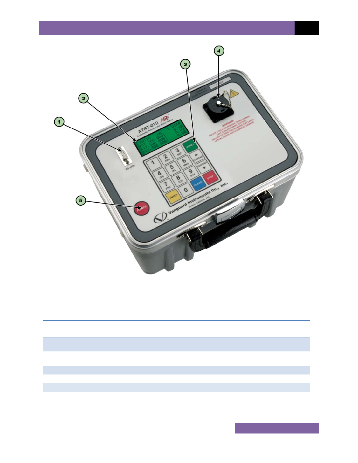
1.3 Controls and Indicators
The ATRT-01 S2, ATRT-01B S2, and ATRT-01D S2 controls and indicators are shown in Figure 1,
Figure 2, and Figure 3, respectively. A leader line with an index number points to each control
and indicator, which is cross-referenced to a functional description in the corresponding table.
The purpose of the controls and indicators may seem obvious, but users should familiarize
themselves with them before using the ATRT. Accidental misuse of the controls will usually
cause no serious harm. Users should also familiarize themselves with the safety summary
information found on the front page of this User’s Manual.
7
Page 12
ATRT-01 S2, ATRT-01B S2, AND ATRT-01D S2 USER’S MANUAL REV 2
Item
Number
1
2
3
4
5
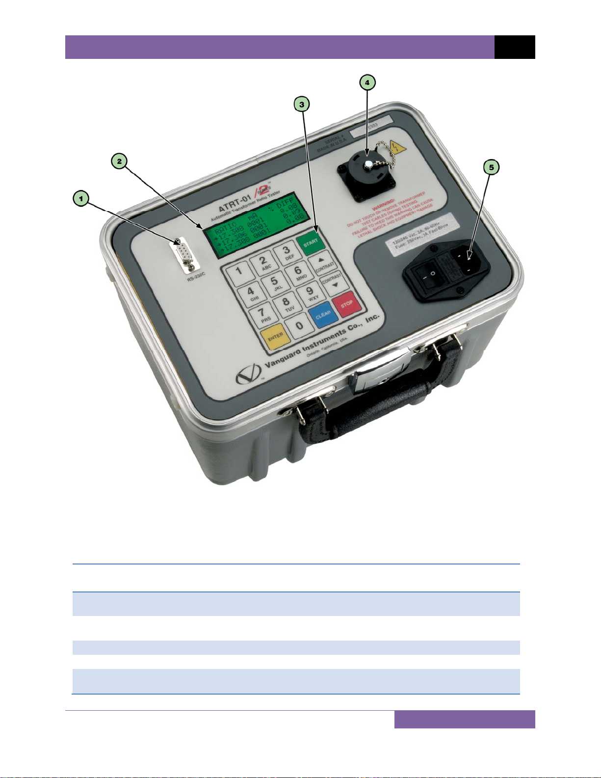
Figure 1. ATRT-01 S2 Controls and Indicators
Table 4. Functional Descriptions of ATRT-01 S2 Controls and Indicators
Panel Markings Functional Description
RS-232C
Rugged alpha-numeric keypad.
H and X lead connecto r; 16-pin male.
120 Vac, 2A,
50-60Hz
RS-232C computer interface port. Data rate is set to 19,200 baud, 1 start bit, 8
data bits, 2 stop bits, and no parity bit.
Back-lit LCD screen (20 characters by 4 lines), viewable in bright sunlight and
low-light levels.
Input power connector and fused power sw itch with th ird-w ire safe ty grou nd.
8
Page 13
REV 2 ATRT-01 S2, ATRT-01B S2, AND ATRT-01D S2 USER’S MANUAL
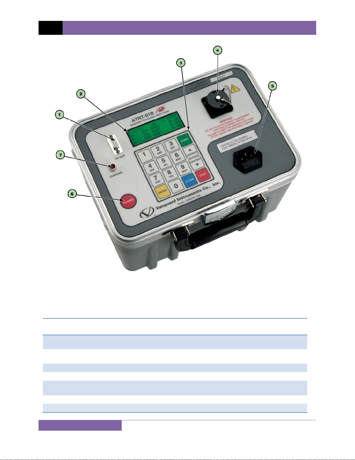
Table 5. Functional Descriptions of ATRT-01B S2 Controls and Indicators
Item
Number
1
2
3
4
5
6
7
Panel Markings Functional Description
RS-232C
120 Vac, 2A,
50-60Hz
POWER Power switch, momentary contact.
CHARGER Battery charging indicator. LED lights up when ba tte ry is being ch arged .
9
Figure 2. ATRT-01B S2 Controls and Indicators
RS-232C computer interface port. Data rate is set to 19,200 baud, 1 start bit, 8
data bits, 2 stop bits, and no parity bit.
Rugged alpha-numeric keypad.
H and X lead connecto r; 16-pin male.
Back-lit LCD screen (20 characters by 4 lines), viewable in bright sunlight and
low-light levels.
Input power connector and fused power sw itch with th ird-w ire safe ty grou nd.
Page 14
ATRT-01 S2, ATRT-01B S2, AND ATRT-01D S2 USER’S MANUAL REV 2
Item
Number
1
2
3
4
5
Figure 3. ATRT-01D S2 Controls and Indicators
Table 6. Functional Descriptions of ATRT-01D S2 Controls and Indicators
Panel Markings Functional Description
RS-232C
Rugged alpha-numeric keypad.
H and X lead connecto r; 16-pin male.
POWER Power sw itch, momentary contact.
RS-232C computer interface port. Data rate is set to 19,200 baud, 1 start bit, 8
data bits, 2 stop bits, and no parity bit.
Back-lit LCD screen (20 characters by 4 lines), viewable in bright sunlight and
low-light levels.
10
Page 15
REV 2 ATRT-01 S2, ATRT-01B S2, AND ATRT-01D S2 USER’S MANUAL
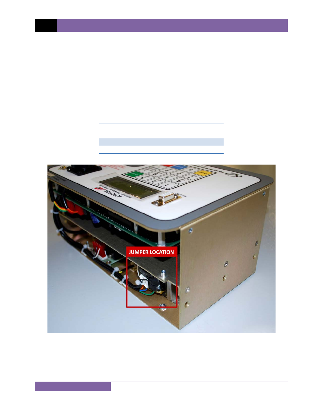
2.0 PRE-TEST SETUP
2.1 ATRT-01 S2 Operating Voltages
The ATRT-01 S2 is powered by ac line voltage only. The operating voltage is preset at the
factory and is selectable between 100-120 Vac, 50/60 Hz or 200-240 Vac, 50/60 Hz. Only the
reference transformer requires voltage selection for the different operating voltages. The
voltage is set by placing jumper(s) on the transformer (part number 200466-1) as shown in
Figure 5 and Figure 6.
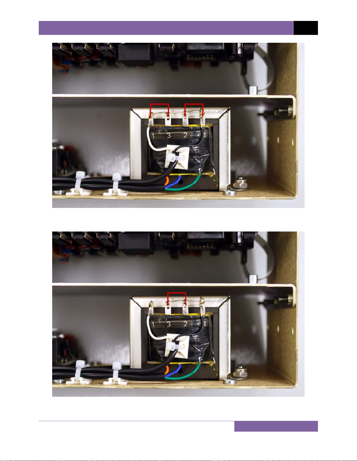
Table 7. ATRT-01 S2 Voltage Selection Jumper Settings
Voltage
Selection
100 – 120 Vac
200 – 240 Vac
Transformer Jumpers
Pin 1 and 3, Pin 2 and 4
Pin 2 and 3
11
Figure 4. ATRT-01 S2 Voltage Selection Jumper Location
Page 16
ATRT-01 S2, ATRT-01B S2, AND ATRT-01D S2 USER’S MANUAL REV 2
Figure 5. ATRT-01 S2 100 – 120 Vac Jumper Settings
Figure 6. ATRT-01 S2 200 – 240 Vac Jumper Settings
12
Page 17

REV 2 ATRT-01 S2, ATRT-01B S2, AND ATRT-01D S2 USER’S MANUAL
2.2 ATRT-01B S2 Operating Power
The ATRT-01B S2 is powered by a rechargeable (6 Vdc / 7 AH) sealed lead acid gel battery. The
unit can operate continuously for up to 6 hours between charges. It can also be used while
charging. Plugging the ATRT-01B S2 into an ac power outlet after the battery is fully charged will
not damage the battery.
• It is recommended that the ATRT-01B S2 be plugged into an ac outlet when it is
NOTES
not in use.
• The ATRT-01B S2 battery can be replaced with the Panasonic model
LC-R122R2PU battery.
2.3 ATRT-01D S2 Operating Power
The ATRT-01D S2 is powered by six standard D cell batteries. We recommend industrial (1.5
volts) D cells such as the Duracell 1300.
To turn the unit on or off, press and hold the [POWER] switch for 2 seconds.
2.4 LCD Screen Contrast Control
To increase the LCD screen contrast, press and hold the [∧ Contrast] key for two seconds.
Release the button when the desired contrast level has been reached.
To decrease the LCD screen contrast, press and hold the [∨ Contrast] key for two seconds.
Release the button when the desired contrast level has been reached.
For the ATRT-01B S2 and ATRT-01D S2, the back-light turns off after 30 seconds of operation to
conserve power. Press any key on the keypad to re-light the back-light.
13
Page 18
ATRT-01 S2, ATRT-01B S2, AND ATRT-01D S2 USER’S MANUAL REV 2
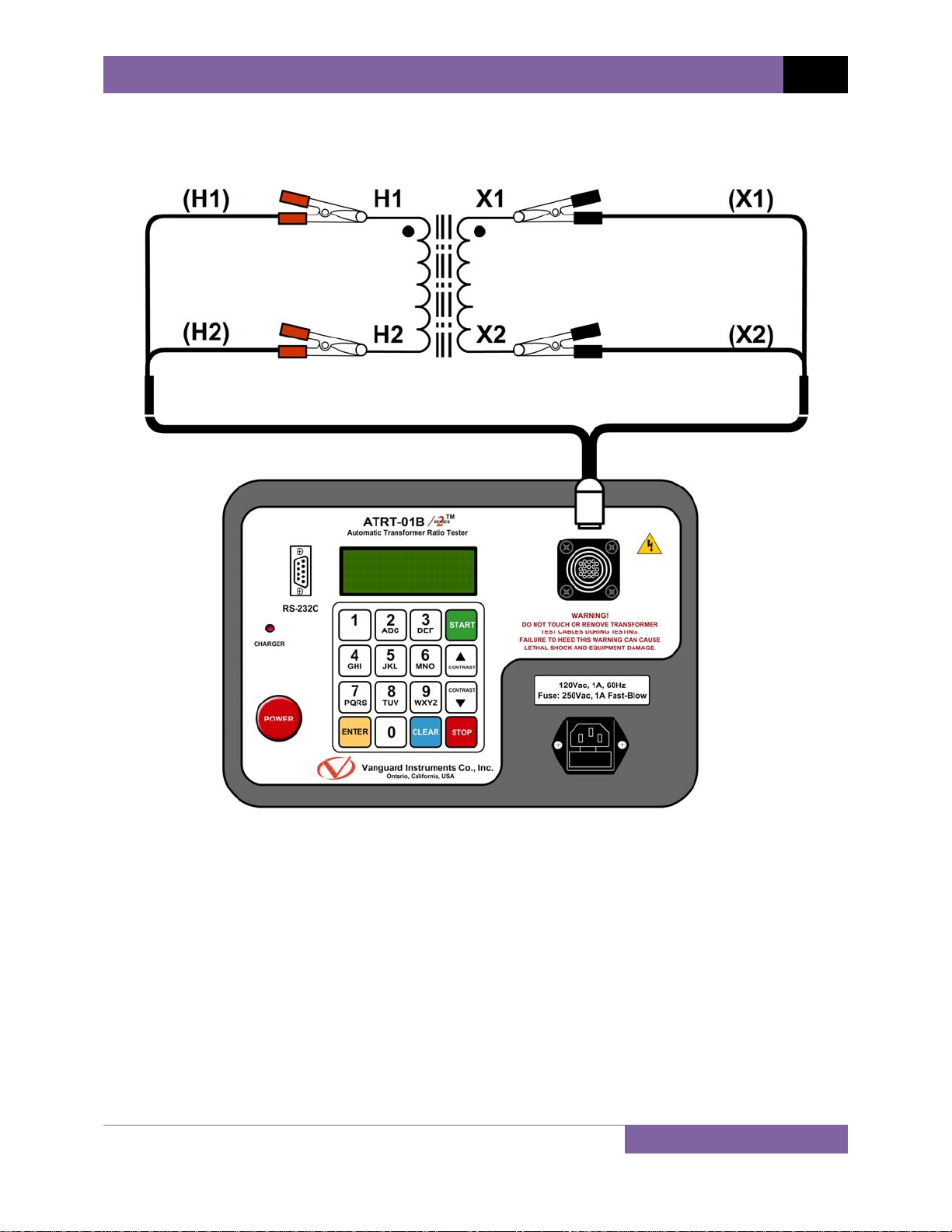
3.0 OPERATING PROCEDURES
3.1 ATRT Transformer Connection Diagrams
Figure 7. Typical Single-Phase Transformer Connection
14
Page 19

REV 2 ATRT-01 S2, ATRT-01B S2, AND ATRT-01D S2 USER’S MANUAL
15
Figure 8. Typical Auto Transformer Connection
Page 20

ATRT-01 S2, ATRT-01B S2, AND ATRT-01D S2 USER’S MANUAL REV 2
Figure 9. Typical CT Connection
16
Page 21

REV 2 ATRT-01 S2, ATRT-01B S2, AND ATRT-01D S2 USER’S MANUAL
Figure 10. Typical Bushing CT Connection on a Single Transformer
17
Page 22

ATRT-01 S2, ATRT-01B S2, AND ATRT-01D S2 USER’S MANUAL REV 2
3.2 Setting the Test Voltage
The ATRT offers two test voltages, 8 Vac and 40 Vac. The unit always defaults to 40 Vac at
power-on. The 8 Vac test voltage can be used in situations where the 40 Vac excitation voltage
may saturate the CT’s. To set the test voltage:
a. Turn on the unit and start from the “ START-UP” menu:
1.TEST XFMR 06/02/10
2.SETUP 15:33:10
3.CALCULATOR
Press the
[2] key (SETUP).
b. The following screen will be displayed:
1.SET TIME
2.SET TEST VOLTAGE
3.COMPUTER CONTROL
Press the
[2] key (SET TEST VOLTAGE).
c. The following screen will be displayed:
1.SET 8 VOLTS
2.SET 40 VOLTS
Press the [1] key (SET 8 VOLTS) to select 8 volts as the test voltage ore press the [2] key
(SET 40 VOLTS) to select 40 volts as the test voltage.
d. The voltage will be set and the following confirmation message will be displayed:
TEST VOLTAGE SET TO
8 VOLTS
ANY KEY TO CONTINUE
Press any key to return to the “START-UP” menu.
18
Page 23

REV 2 ATRT-01 S2, ATRT-01B S2, AND ATRT-01D S2 USER’S MANUAL
3.3 Enabling the Computer Interface
The ATRT can be connected to a computer via the RS-232C interface port. In order to remotely
control the unit using the provided Transformer Turns Ratio Analysis (TTRA) software, the unit
must be placed in Computer Control mode. Use the steps below to place the unit in Computer
Control mode:
a. Start from the “START-UP” menu:
1.TEST XFMR 06/02/10
2.SETUP 15:33:10
3.CALCULATOR
Press the [2] key (SETUP).
b. The following screen will be displayed:
1.SET TIME
2.SET TEST VOLTAGE
3.COMPUTER CONTROL
Press the [3] key (COMPUTER CONTROL).
c. The following screen will be displayed confirming that the unit has been placed in
Computer Control mode:
COMPUTER ITF MODE
*** CAUTION! ***
CABLES MAY HAVE VLTG
“STOP” TO ABORT
You can now use the Transformer Analysis software to remotely control the unit from
the PC. Please see the software User’s Manual for further information.
Press the
[STOP] key to abort Computer Control mode and return to the “START-UP”
menu.
The TTRA software only supports the single phase transformer test when used
with the ATRT-01 S2.
NOTE
19
Page 24

ATRT-01 S2, ATRT-01B S2, AND ATRT-01D S2 USER’S MANUAL REV 2
3.4 Setting the Date and Time
To set the date and time:
a. Start from the “START-UP” menu:
1.TEST XFMR 06/02/10
2.SETUP 15:33:10
3.CALCULATOR
Press the [2] key (SETUP).
b. The following screen will be displayed:
1.SET TIME
2.SET TEST VOLTAGE
3.COMPUTER CONTROL
Press the [2] key (SET TIME)
c. The following screen will be displayed:
ENTER
MM-DD-YY HH:MM:SS
_
Type in the date and time using the alpha-numeric keypad. When the complete date
and time has been entered, you will be immediately returned to the “START-UP” menu.
20
Page 25

REV 2 ATRT-01 S2, ATRT-01B S2, AND ATRT-01D S2 USER’S MANUAL
3.5 Performing Tests
3.5.1. Testing a Single Phase Transformer
Follow the steps below to test a single phase transformer:
a. Start from the “START-UP” menu:
1.TEST XFMR 06/02/10
2.SETUP 15:33:10
3.CALCULATOR
Press the [1] key (TEST XFMR).
b. The following screen will be displayed:
XFMR CONFIGURATION:
1.SNGL PHS 2.dT-Y
3.Y-dT 4.dT-dT
5.Y-Y
Press the [1] key (SNGL PHS).
c. The following screen will be displayed:
XFMR NAME PLATE VLTG
1. YES
2. NO
1. YES
Press the [1] key (YES) if you would like to enter the transformer name plate
voltage values. The following screen will be displayed:
ENTER H WINDING
NAME-PLATE VOLTAGE:
V
Type the H winding name plate voltage value using the numeric keypad. The
screen will be updated as shown:
ENTER H WINDING
NAME-PLATE VOLTAGE:
500 V
Press the
21
[ENTER] key. The following screen will be displayed:
Page 26

ATRT-01 S2, ATRT-01B S2, AND ATRT-01D S2 USER’S MANUAL REV 2
ENTER X WINDING
NAME-PLATE VOLTAGE:
V
Type the X winding name plate voltage value using the numeric keypad. The
screen will be updated as shown:
ENTER H WINDING
NAME-PLATE VOLTAGE:
10 V
Press the [ENTER] key. Continue to step d.
2. NO
Press the [2] key (NO) if you do not want to enter the transformer name plate
voltage. Continue to step d.
d. The following screen will be displayed:
SINGLE PHASE XFORMER
“START” TO RUN TEST
OR
“STOP” TO ABORT
Press the [START] key to start the test.
e. The following screen will be displayed while the test is being performed:
SINGLE PHASE XFORMER
PLEASE WAIT
TEST IN PROGRESS
The test results will be displayed on the LCD screen when testing has finished:
The polarity is displayed as either a plus sign (+) for “in-phase” or a minus sign (-) for
“out-of-phase”. The value listed under “% DIFF” is the percentage error.
Press any key to continue.
22
Page 27

REV 2 ATRT-01 S2, ATRT-01B S2, AND ATRT-01D S2 USER’S MANUAL
f. The following screen will be displayed:
REPEAT TEST?
1. YES
2. NO
Press the [2] key (NO). You will be returned to the “START-UP” screen.
23
Page 28

ATRT-01 S2, ATRT-01B S2, AND ATRT-01D S2 USER’S MANUAL REV 2
3.5.2. Testing a Three Phase Transformer
Follow the steps below to test a three phase transformer:
a. Start from the “START-UP” menu:
1.TEST XFMR 06/02/10
2.SETUP 15:33:10
3.CALCULATOR
Press the [1] key (TEST XFMR).
b. The following screen will be displayed:
XFMR CONFIGURATION:
1.SNGL PHS 2.dT-Y
3.Y-dT 4.dT-dT
5.Y-Y
Select a three-phase transformer test by pressing the corresponding key ([2] to [5]). For
this example, press the [2] key (dT-Y) to select the Delta to Y phase transformer test.
c. The following screen will be displayed:
dT-Y XFMR CONFIG:
1.Dyn1 2.Dyn3
3.Dyn5 4.Dyn7
5.Dyn9 6.Dyn11
Select the transformer configuration by pressing the corresponding key ([1] to [6]). For
this example, press the [1] key (Dyn1).
d. The following screen will be displayed:
XFMR NAME PLATE VLTG
1. YES
2. NO
1. YES
Press the [1] key (YES) if you would like to enter the transformer name plate
voltage values. The following screen will be displayed:
ENTER H WINDING
NAME-PLATE VOLTAGE:
V
Type the H winding name plate voltage value using the numeric keypad. The
screen will be updated as shown:
24
Page 29

REV 2 ATRT-01 S2, ATRT-01B S2, AND ATRT-01D S2 USER’S MANUAL
ENTER H WINDING
NAME-PLATE VOLTAGE:
500 V
Press the [ENTER] key. The following screen will be displayed:
ENTER X WINDING
NAME-PLATE VOLTAGE:
V
Type the X winding name plate voltage value using the numeric keypad. The
screen will be updated as shown:
ENTER H WINDING
NAME-PLATE VOLTAGE:
10 V
Press the [ENTER] key. Continue to step e.
2. NO
Press the [2] key (NO) if you do not want to enter the transformer name plate
voltage. Continue to step e.
e. The following screen will be displayed showing the Phase A cable connections for the
selected test (this will differ depending on the test):
CABLE PHS-A XFMR
X1,X2 to X1,X0
H1,H2 to H1,H3
“START” TO RUN TEST
Make the cable connections per the instructions and then press the
[START] key to
run the Phase A test.
f. The following screen will be displayed while the test is being performed:
DYN 1 TRANSFORMER
PLEASE WAIT...
25
Page 30

ATRT-01 S2, ATRT-01B S2, AND ATRT-01D S2 USER’S MANUAL REV 2
The Phase A test results will be displayed on the LCD screen when testing has finished:
RATIO mA % DIFF
+15.003 001 0.02
“ENTER” TO CONTINUE
Press the [ENTER] key to continue.
g. The following screen will be displayed showing the Phase B cable connections for the
selected test:
CABLE PHS-B XFMR
X1,X2 to X2,X0
H1,H2 to H2,H1
“START” TO RUN TEST
Make the cable connections per the instructions and then press the [START] key to
run the Phase B test.
h. The following screen will be displayed while the test is being performed:
DYN 1 TRANSFORMER
PLEASE WAIT...
The Phase A and B test results will be displayed on the LCD screen when testing has
finished:
RATIO mA % DIFF
+15.003 001 0.02
+15.015 001 0.10
“ENTER” TO CONTINUE
Line 1 of the results shows the Phase A test results, and line 2 shows the Phase B test
results.
Press the [ENTER] key to continue.
i. The following screen will be displayed showing the Phase C cable connections for the
selected test:
CABLE PHS-C XFMR
X1,X2 to X3,X0
H1,H2 to H3,H2
“START” TO RUN TEST
Make the cable connections per the instructions and then press the [START] key to run
the Phase C test.
26
Page 31

REV 2 ATRT-01 S2, ATRT-01B S2, AND ATRT-01D S2 USER’S MANUAL
j. The following screen will be displayed while the test is being performed:
DYN 1 TRANSFORMER
PLEASE WAIT...
The Phase A, B, and C test results will be displayed on the LCD screen when testing has
finished:
Press any key to continue.
k. The following screen will be displayed:
REPEAT TEST?
1. YES
2. NO
Press the [2] key (NO). You will be returned to the “START-UP” menu.
27
Page 32

ATRT-01 S2, ATRT-01B S2, AND ATRT-01D S2 USER’S MANUAL REV 2
3.5.3. Performing a Quick Test
The ATRT provides a Quick Test mode that can be used to measure a transformer’s turns ratio
by only pressing a single button. To initiate a Quick Test:
a. Start from the “START-UP” menu:
1.TEST XFMR 06/02/10
2.SETUP 15:33:10
3.CALCULATOR
Press and hold down the [START] key.
b. The following screen will be displayed:
“QUICK TEST”
HOLD START KEY UNTIL
BEEP FOR QUICK TEST
Continue to hold down the [START] key until the unit beeps again, and then release
the [START] key.
c. The following screen will be displayed while the test is being performed:
SINGLE PHASE XFORMER
PLEASE WAIT
TEST IN PROGRESS
The test results will be displayed on the LCD screen when testing has finished:
RATIO mA
+1.003 0002
Press the
[STOP] key to return to the “START-UP” menu.
28
Page 33

REV 2 ATRT-01 S2, ATRT-01B S2, AND ATRT-01D S2 USER’S MANUAL
3.5.4. Performing a Single Phase Transformer Test Using Preset Voltage Table
The ATRT is pre-programmed with 46 transformer name plate voltages. These pre-programmed
values can be used to quickly test a single phase transformer’s turns ratio and compare the test
results against the name plate voltage. Please see Table 8 for a list of the pre-programmed
name plate voltages. Follow the steps below to perform a single phase transformer test using a
pre-programmed name plate voltage:
a. Start from the “START-UP” menu:
1.TEST XFMR 06/02/10
2.SETUP 15:33:10
3.CALCULATOR
Press the [CLEAR] key.
b. The following screen will be displayed:
SCROLL TO SELECT
“START” TO RUN TEST
H = 2,400
X = 120
Press either the [∧ Contrast] key or the [∨ Contrast] key to scroll through the preprogrammed name plate voltage values.
Continue to press the [∧ Contrast] key or the [∨ Contrast] key until the desired
name plate voltage values are displayed on the screen.
Press the [START] key when the desired name plate voltage values are displayed.
c. The following screen will be displayed while the test is being performed:
SINGLE PHASE XFORMER
PLEASE WAIT
TEST IN PROGRESS
The test results will be displayed on the LCD screen when testing has finished (multiple
examples shown:
M-RATIO=+20.05
ERROR= 0.25 %
PASSED TTR TEST
2,400/120 R=20.00
Example results from a passed test Example results from a failed test
using nameplate voltages. using nameplate voltages.
M-RATIO=+20.05
ERROR= 2.5 %
FAILED TTR TEST
2,400/120 R=20.00
29
Page 34

ATRT-01 S2, ATRT-01B S2, AND ATRT-01D S2 USER’S MANUAL REV 2
Please see Figure 11 below for a description of the test results elements.
Figure 11. Test Results Elements
In order for a test to pass, the error reading must be less than or equal to
0.5% and the winding must be in-phase (+).
NOTE
30
Page 35

REV 2 ATRT-01 S2, ATRT-01B S2, AND ATRT-01D S2 USER’S MANUAL
Table 8. Pre-programmed Nameplate Voltages
No H Voltage X Voltage
1 2400 120
2 2400 240
3 2400 277
4 2400 480
5 4160 120
6 4160 240
7 4160 277
8 4160 480
9 4800 120
10 4800 240
11 6930 120
12 6930 240
13 7200 2400
14 9430 120
15 9430 240
16 12000 120
17 12000 240
18 12000 277
19 12000 480
20 12000 2400
21 13800 120
22 13800 240
23 13800 277
24 13800 480
25 14400 120
26 14400 240
27 14400 277
28 14400 480
29 16340 120
30 16340 240
31 16340 277
32 16340 480
33 16340 2400
34 24900 120
35 24900 240
36 24900 277
37 34400 120
38 34400 240
39 34400 277
40 34400 480
41 34400 2400
42 34400 4800
43 34400 6930
44 34400 7200
45 34400 9430
31
Page 36

ATRT-01 S2, ATRT-01B S2, AND ATRT-01D S2 USER’S MANUAL REV 2
APPENDIX A – TRANSFORMER VECTOR GROUP CODES
Utility power transformers manufactured in accordance with IEC specifications have a Rating
Plate attached in a visible location. This plate contains a list of the transformer's configuration
and operating specifications. One such rating is the winding configuration and phasedisplacement code. This code follows a convention that comprises letter and number sets that
denote three-phase winding configurations (i.e., Wye, delta, or zig-zag). Letter symbols for the
different windings are noted in descending order of their rated voltages. That is, symbols
denoting higher voltage ratings will be in upper-case letters and symbols denoting lower or
intermediate voltage ratings will be in lower-case letters. If the neutral point of either a wye or
zig-zag winding is brought out, the indication will be an N (high voltage) or n (lower voltage).
The end numeral is a 300 multiplier that indicates phase lag between windings.
Accordingly, the following standard practice applies:
Wye (or star) = Y (high voltage) or y (low voltage)
Delta = D (high voltage) or d (low voltage)
Zig-zag = Z (high voltage) or z (low voltage)
For example, Dyn11 decodes as follows:
D indicates that the high-voltage windings are connected in a Delta configuration
(Since delta windings do not have a neutral point, the N never appears after a D).
y indicates that the lower voltage winding is in a wye (or star) configuration.
n indicates that the lower voltage windings have the neutral point brought out.
11 indicates a phase-displacement lag of 330 degrees between the Wye and the Delta
winding.
32
Page 37

REV 2 ATRT-01 S2, ATRT-01B S2, AND ATRT-01D S2 USER’S MANUAL
APPENDIX B – Common ANSI Transformer Descriptions
33
Page 38

ATRT-01 S2, ATRT-01B S2, AND ATRT-01D S2 USER’S MANUAL REV 2
34
Page 39

REV 2 ATRT-01 S2, ATRT-01B S2, AND ATRT-01D S2 USER’S MANUAL
35
Page 40

ATRT-01 S2, ATRT-01B S2, AND ATRT-01D S2 USER’S MANUAL REV 2
36
Page 41

REV 2 ATRT-01 S2, ATRT-01B S2, AND ATRT-01D S2 USER’S MANUAL
37
Page 42

ATRT-01 S2, ATRT-01B S2, AND ATRT-01D S2 USER’S MANUAL REV 2
38
Page 43

REV 2 ATRT-01 S2, ATRT-01B S2, AND ATRT-01D S2 USER’S MANUAL
39
Page 44

ATRT-01 S2, ATRT-01B S2, AND ATRT-01D S2 USER’S MANUAL REV 2
40
Page 45

REV 2 ATRT-01 S2, ATRT-01B S2, AND ATRT-01D S2 USER’S MANUAL
APPENDIX C – CEI/IEC 60076-1 Transformer Descriptions
41
Page 46

ATRT-01 S2, ATRT-01B S2, AND ATRT-01D S2 USER’S MANUAL REV 2
42
Page 47

REV 2 ATRT-01 S2, ATRT-01B S2, AND ATRT-01D S2 USER’S MANUAL
43
Page 48

ATRT-01 S2, ATRT-01B S2, AND ATRT-01D S2 USER’S MANUAL REV 2
44
Page 49

REV 2 ATRT-01 S2, ATRT-01B S2, AND ATRT-01D S2 USER’S MANUAL
45
Page 50

ATRT-01 S2, ATRT-01B S2, AND ATRT-01D S2 USER’S MANUAL REV 2
46
Page 51

REV 2 ATRT-01 S2, ATRT-01B S2, AND ATRT-01D S2 USER’S MANUAL
47
Page 52

ATRT-01 S2, ATRT-01B S2, AND ATRT-01D S2 USER’S MANUAL REV 2
APPENDIX D – Australian Std.2374 Transformer Descriptions
48
Page 53

REV 2 ATRT-01 S2, ATRT-01B S2, AND ATRT-01D S2 USER’S MANUAL
49
Page 54

ATRT-01 S2, ATRT-01B S2, AND ATRT-01D S2 USER’S MANUAL REV 2
50
Page 55

REV 2 ATRT-01 S2, ATRT-01B S2, AND ATRT-01D S2 USER’S MANUAL
51
Page 56

ATRT-01 S2, ATRT-01B S2, AND ATRT-01D S2 USER’S MANUAL REV 2
52
Page 57

REV 2 ATRT-01 S2, ATRT-01B S2, AND ATRT-01D S2 USER’S MANUAL
53
Page 58

ATRT-01 S2, ATRT-01B S2, AND ATRT-01D S2 USER’S MANUAL REV 2
54
Page 59

1520 S. Hellman Ave • Ontario, CA 91761 • USA
Phone: 909-923-9390 • Fax: 909-923-9391
www.vanguard-instruments.com
Copyright © 2010 by Vanguard Instruments Company, Inc.
ATRT-01/01B/01D S2 User’s Manual • Revision 2.0 • July 13, 2010 • TA
 Loading...