

Vanguard Aristocrat V36E Installation Instructions Manual

®
INSTALLATION INSTRUCTIONS
SAVE THIS BOOK
This book is valuable. In addition to instructing you on how to install
and maintain your appliance, it also contains information that will
enable you to obtain replacement parts or optional accessory items
when needed. Keep it with your other important papers.
ARISTOCRAT™
MODEL V36E
WOOD-BURNING FIREBOX
40
22 1/16''
5/8''
1
/4"
33
12 3/8"
OUTER PIPE
1
13
/16''
ROUND TOP
TERMINATION
(VRTL-8DM)
1
/8"
36''
41''
1
9
/2''
8"
9"
5
/8"
19
1" X 33" LONG FIBERGLASS
INSULATION REQUIRED
(BOTH ENDS) BETWEEN NAILING
FLANGE AND WOOD FRAMING
22 1/8''
7
4
/8"
AIR KIT
KNOCK-OUT
GAS LINE
KNOCK-OUT
3/4" MIN. CLEARANCE
ALL AROUND EXCEPT
AT NAILING FLANGE
0" TO
TOP OF
SPACER
17 1/2"
35 3/4"
STORM
COLLAR
FLASHING
FIRESTOP
2 IN. MIN.
AIR SPACE TO
COMBUSTIBLES
AROUND PIPE
16 3/4"
VET-8DM or
VETL-8DM
TERMINATION
DRYWALL CAN COME
UP TO OUTER PERIMETER
OF FRONT FACE
NO COMBUSTIBLE
MATERIAL ON FRONT
FACE
®
DESA INTERNATIONAL,
2701 INDUSTRIAL DRIVE
P.O. BOX 90004
Model
Serial No.
BOWLING GREEN, KY
42102-9004
Date Purchased
OUTSIDE AIR
(LEFT SIDE ONLY)
0" TO
FLOOR
HEARTH
EXTENSION
52" X 16"
14" MIN. TO
ADJACENT WALL
3" IF USING
PWS-36 WALL SHIELD
8" EACH
SIDE
55508
Rev. B
08/99

41 3/4"
42
1
/4"
22
7
/8"
10
1
/4"
FOR YOUR SAFETY
• Do not store or use gasoline or any other flammable vapors or liquids in the vicinity of this or any
other appliance.
• Due to high temperatures, the appliance should be
located out of traffic and away from furniture and
draperies.
• Do not place clothing or other flammable materials
on or near the appliance.
• NEVER leave children unattended when a fire is
burning in the firebox.
WARNING: IMPROPER INSTALLATION, ADJUSTMENT, ALTERATION, SERVICE OR MAINTENANCE
CAN CAUSE INJURY, PROPERTY DAMAGE, OR LOSS
OF LIFE. REFER TO THIS MANUAL. FOR ASSISTANCE OR ADDITIONAL INFORMATION CONSULT A
QUALIFIED INSTALLER OR LOCAL DISTRIBUTOR.
WARNING: THIS FIREBOX IS INTENDED FOR USE
WITH WOOD, OR IF A VENT-FREE OR DECORATIVE
GAS APPLIANCE IS INSTALLED, BURN PROPANE
OR NATURAL GAS ONLY.
CHECK LOCAL CODES PRIOR TO INSTALLATION
WARNING: DO NOT PACK REQUIRED CLEARANCE
SPACES WITH INSULATION OR OTHER MATERIALS.
HEIGHT
The minimum height of the chimney, measured from the base of the
fireplace to the flue gas outlet, is 14 feet for straight flues or a flue
with one elbow set. For the systems with two-elbow sets, the
minimum height is 22 feet. The maximum height of any system is 60
feet; this measurement includes the fireplace, chimney sections and
the effective height of the termination assembly
INSTALLING THE FIREPLACE
STEP 1: Frame the opening for the fireplace using dimensions
shown in Figures 1, 2, or 3.
STEP 2: Set the fireplace directly in front of this opening and slide
back until the nailing flanges on each side are about 1/4" away from
the prepared wood framing. Before securing to wood framing, make
sure the fiberglass insulation strip (provided) is place between frame
and nailing flange (see illustration on front cover).
INTRODUCTION
Before beginning the installation of your fireplace, read these
instructions through completely.
These DESA International components and this fireplace are designed and manufactured for satisfactory performance when installed and used according to this manual. Unless you use DESA
International components, which have been designed and tested for
this fireplace system, you may cause a fire hazard.
Careless or improper operation may also cause a fire hazard.
The DESA International warranty does not cover, and DESA Inter-
national disclaims any responsibility for, damage or malfunction
caused by the following actions.
A)Modification of the fireplace, components, doors, air inlet sys-
tem and damper control.
B) Use of any component part not manufactured or approved by
DESA International in combination with an DESA International
fireplace system.
This wood burning fireplace complies with UL 127 as a
FACTORY BUILT FIREPLACE and is listed and tested by
Underwriters Laboratory Inc.
This model is not for use in mobile homes.
MINIMUM CLEARANCE TO COMBUSTIBLES
Framing and enclosures may safely make direct contact with the
spacers on the top of the fireplace. The fireplace may sit directly on
combustible flooring. The fireplace opening must not be less than
14" from a combustible, perpendicular sidewall (see front cover). A
2" minimum air space clearance between combustible materials and
the chimney must be absolutely maintained. A 16
chase dimension is recommended as a minimum size. A 3/4 inch air
space is required around back and sides of fireplace.
This firebox is not intended to be used as a substitute for a
furnace to heat an entire home. Use for supplementary
heating only.
1
/2 inch inside
Figure 1
13 1/4"
Maintain 3/4"
air space between
framing and
fireplace.
Figure 2
Maintain 3/4"
air space between
framing and
fireplace.
Figure 3
MIN
3
41
/4"
MIN
3
62
/16"
MIN
5
14
1
10
/2"
MIN
4"
3
24
/4"
FRAMING DIMENSIONS AT 30°
/16"
MIN
43
MIN
7
/8"
STEP 3: Check the level of the fireplace and shim with sheet metal
spacers if necessary.
2
55508
STEP 4: When the fireplace is installed upon a combustible floor a
galvanized sheet ember protector (provided) must be installed between
the fireplace and the hearth extension as illustrated in Figure 16, page 6.
STEP 5: Secure the fireplace to the framing through the flanges
located on the sides on the fireplace with 8-penny nails.
NOTE:
The 3/4" clearance is not required at the nailing flange (see
Figure 18).
ASSEMBLING AND INSTALLING YOUR
DOUBLE-WALL CHIMNEY SYSTEM
Each double wall chimney section consists of an outer pipe, flue pipe
and one wire spacer. The pipe sections are not united and must be
assembled independently as the chimney is installed. When starting
the chimney directly on the fireplace, the flue pipe section must be
installed first, with the hemmed end down. The outer pipe section
can then be installed over the flue pipe section with the hemmed end
up (see Figure 4).
Press down on each pipe section until the lances on the lower end
securely engage the knurl on the fireplace starting collar. The wire
spacer will assure the proper figure spacing between the inner and
outer pipe sections.
WARNING: THE OPENINGS IN THE COLLAR AROUND
THE BASE OF THE CHIMNEY AT THE TOP OF THE
FIREPLACE MUST NOT BE OBSTRUCTED. NEVER
USE BLOWN INSULATION TO FILL THE CHIMNEY
ENCLOSURE (SEE FIGURE 5).
Continue to assemble chimney sections as outlined above, making
sure that both inner outer pipe sections are locked together. When
installing double wall "snap lock" chimney together, it is important
to assure the joints between the chimney's sections are locked. Check
by pulling chimney upward after locking. The chimney will not
come apart if properly locked. It is not necessary to add screws to
keep the chimney together.
LINEAL GAIN CHART
PART # NO. DESCRIPTION LINEAL GAIN
V36E FIREPLACE 40"
V12-8DM PIPE SECTION 10 5/8"
V18-8DM PIPE SECTION 16 5/8"
V24-8DM PIPE SECTION 23 5/8"
V36-8DM PIPE SECTION 34 5/8"
V48-8DM PIPE SECTION 46 5/8"
VRTL-8DM ROUND TOP TERMINATION 6"
VETL-8DM CHASE TERMINATION 1" to 12"
3
12
LINEAL GAIN:
THE ACTUAL
MEASURABLE
LENGTH OF A
PART AFTER
TWO OR MORE
PARTS ARE
CONNECTED.
/8 GALVANIZED
OUTER PIPE
HEMMED
END
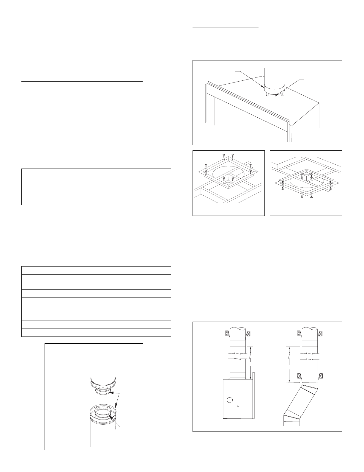
FIRESTOP SPACERS
Firestop spacers are required at each point where the chimney
penetrates a floor or ceiling joist space. Their purpose is two fold;
they establish and maintain the required clearance between the
chimney and combustible materials.
FIREPLACE
COLLAR
KEEP THIS
AREA OPEN
Figure 5
Figure 6
Figure 7
They also provide complete separation from one floor space to
another floor or attic space as required by most codes.
When the double wall pipe passes through a framed opening into an attic
space, the firestop must be place into the attic floor as in Figure 6.
When the pipe passes through a framed opening into a living space
above, the firestop must be placed onto the ceiling from below as in
Figure 7.
SUPPORT SECTIONS
The chimney support section is a 4-strap 12" length of pipe. A chimney
support is required every 30 feet above the fireplace after a straight
chimney run, or above a return elbow after a straight chimney run (see
Figure 8). This support is designed to relieve the extra weight load on
the fireplace and elbow when high chimneys are installed.
V12S-8DM
V12S-8DM
SUPPORT
30 FT.
SUPPORT
30 FT.
RETURN
ELBOW
8 IN.
STAINLESS
INNER PIPE
Figure 4
55508
Figure 8
3
 Loading...