

Page 1

PTB 200 1 (28)
Digital Barometers
SSD/Operating Manual 24th February 1993 PTB200-O0284-1.1
PTB 200 DIGITAL BAROMETERS
1 PRODUCT DESCRIPTION 2
2 INSTALLATION 3
2.1 Mounting 3
2.2 Grounding 4
2.3 Power connections 5
2.4 Serial output mode connections 6
2.5 Pulse output mode connections 7
2.6 Pressure connections 8
2.7 Multiple barometers on one RS 232C bus 9
3 SERIAL COMMANDS 10
3.1 General 10
3.2 Configuration commands 11
3.3 Operating commands 19
4 ADJUSTMENT AND CALIBRATION 22
4.1 Offset and gain adjustment 23
4.2 Multipoint adjustment 24
5 TECHNICAL DATA 26
Appendix 1 Commands
Page 2

PTB200 Digital Barometer
SERIAL COMMANDS
Function Command Comment
serial bus settings SERI
echo on/off ECHO
output format FORM
pressure resolution FORM
units UNIT
integration time MTIM, FILT
settling time/response time MTIM, FILT
sending mode SMODE STOP, RUN and POLL modes
address ADDR for POLL mode only
defining single output
command
sleep mode SLEEP
list of software settings ?
SCOM in STOP and RUN modes
only
Appendix 1
starting output R
stopping output S
output single reading SEND in POLL mode address
required
setting output interval INTV
control of a single barometer
OPEN ,CLOSE
in POLL mode
resetting RESET
error messages ERRS
linear pressure adjustment LP
multipoint correction MPC, MPCI
1994-08-16 1
Page 3

PTB 200 2 (28)
Digital Barometers
SSD/Operating Manual 24th February 1993 PTB200-O0284-1.1
1 PRODUCT DESCRIPTION
The PTB 200 A and PTB 201 A are fully compensated digital barometers designed to operate over a wide pressure and temperature range.
The final factory adjustment and calibration of the PTB 200 A is done
against a deadweight tester for best accuracy and pressure traceability.
The PTB 201 A is adjusted and calibrated by using electronic working
standards to meet the requirements of demanding weather station
applications. The PTB 200 digital barometers can also be readjusted by
the user with a local primary standard at up to eight selectable pressure
levels.
There are three available outputs in the PTB 200 digital barometers.
The RS 232C full duplex serial interface with software selectable serial
bus settings and pressure units is the standard output for connection
with computers. The user can also choose a TTL level bidirectional
serial output. For simple data logger use the pulse output can be
selected. The serial output of the PTB 200 barometers can be used in
continuous, interval or on-demand modes. The pulse output is activated
by an external trigger signal.
The PTB 200 digital barometers have two built-in features to reduce
power consumption; the user can choose a software controlled sleep
mode or use an external trigger signal to shut down the barometer.
The user can define various settings, such as integration time, settling
time and pressure resolution according to his application (see chapters
General and Configuration commands). The factory settings have been
chosen so that both a fast settling time and high resolution are
achieved. In applications where fast settling time is not required, we
recommend longer integration times to suppress noise effects such as
wind turbulance.
The PTB 200 digital barometers use Vaisala’s BAROCAP silicon
capacitive absolute pressure sensor. The BAROCAP pressure sensor
has excellent hysteresis and repeatability characteristics and very good
temperature and long-term stability. The ruggedness of the BAROCAP
sensor is outstanding.
From April 1993, the PTB 200 digital barometers are traceable to NIST
in the USA. Until March 1993 the barometers have been traceable to
L.N.E. in France.
Page 4
PTB 200 3 (28)
Digital Barometers
SSD/Operating Manual 24th February 1993 PTB200-O0284-1.1
2 INSTALLATION
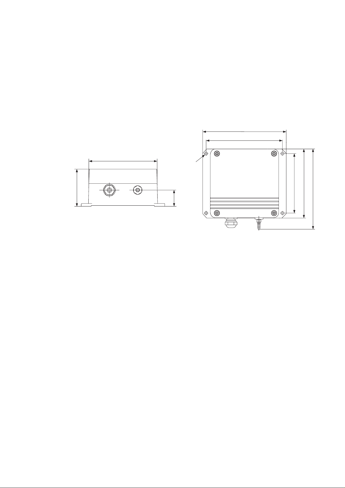
2.1 Mounting
The dimensions and recommended mounting positions of the PTB 200
barometers are shown in Figure 1.
145 (5.71)
133 (5.24)
120 (4.72)
Ø 6.5 (0.26)
65 (2.56)
104 (4.09)
120 (4.72)
139.5 (5.49)
27.5 (1.08)
Fig. 1 Dimensions and mounting of PTB 200 barometers
See Chapter 2.2 Grounding and 2.6 Pressure connection for further
information on electrical grounding and pressure connection
alternatives.
Page 5
PTB 200 4 (28)
Digital Barometers
SSD/Operating Manual 24th February 1993 PTB200-O0284-1.1
2.2 Grounding
A single electrical cable with a screen and five or six wires is
recommended for power and serial bus connections. The cable
diameter should be 5 ... 10 mm.
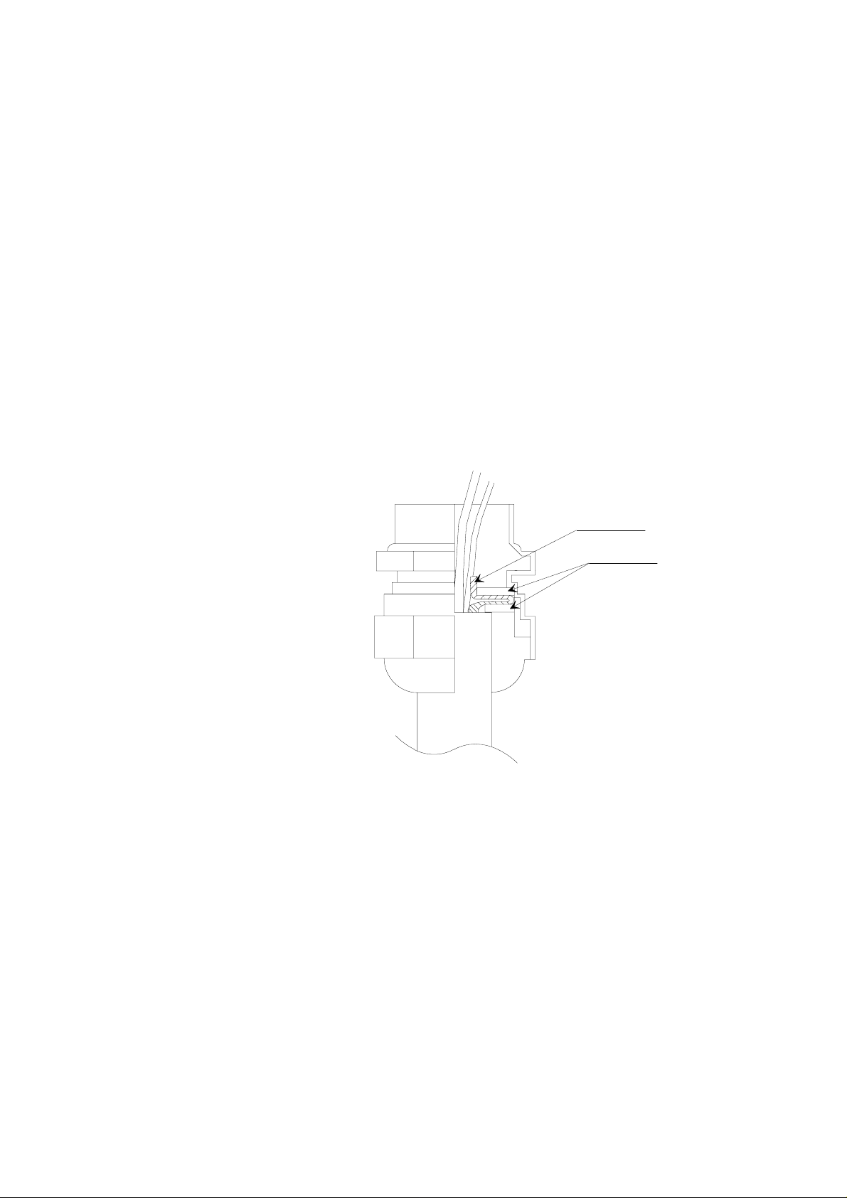
The screen of the electrical cable must be grounded properly to achieve
best possible EMC performance. First remove the bushing from the
barometer housing and then push the cable through the bushing and its
brass disks. Expose the screen braid, but be careful not to open the
braid. Cut the braid and the wires to a suitable length. Pull back the
braid and press it between the two brass disks of the cable bushing to
make a full 360 degrees grounding (see Fig. 2). Then tighten the cable
bushing to the barometer housing.
CABLE SCREEN
BRASS DISKS
Fig. 2 Grounding the cable screening between the two brass disks of
the cable bushing
In addition to grounding the cable screen in the cable bushing, either
the barometer housing or the host end of the cable screen must be
grounded. To ground the barometer housing use one serrated lock
washer between a mounting screw and the housing; the lock washer
breaks the painting of the housing. When the host end of the cable
screen is grounded, the barometer housing must be mounted on an
insulating support to avoid grounding at two points.
Page 6
PTB 200 5 (28)
POWER JUMPER
ON
OFF
-
CTRL
+
normal use
external control
using CTRL line
Digital Barometers
SSD/Operating Manual 24th February 1993 PTB200-O0284-1.1
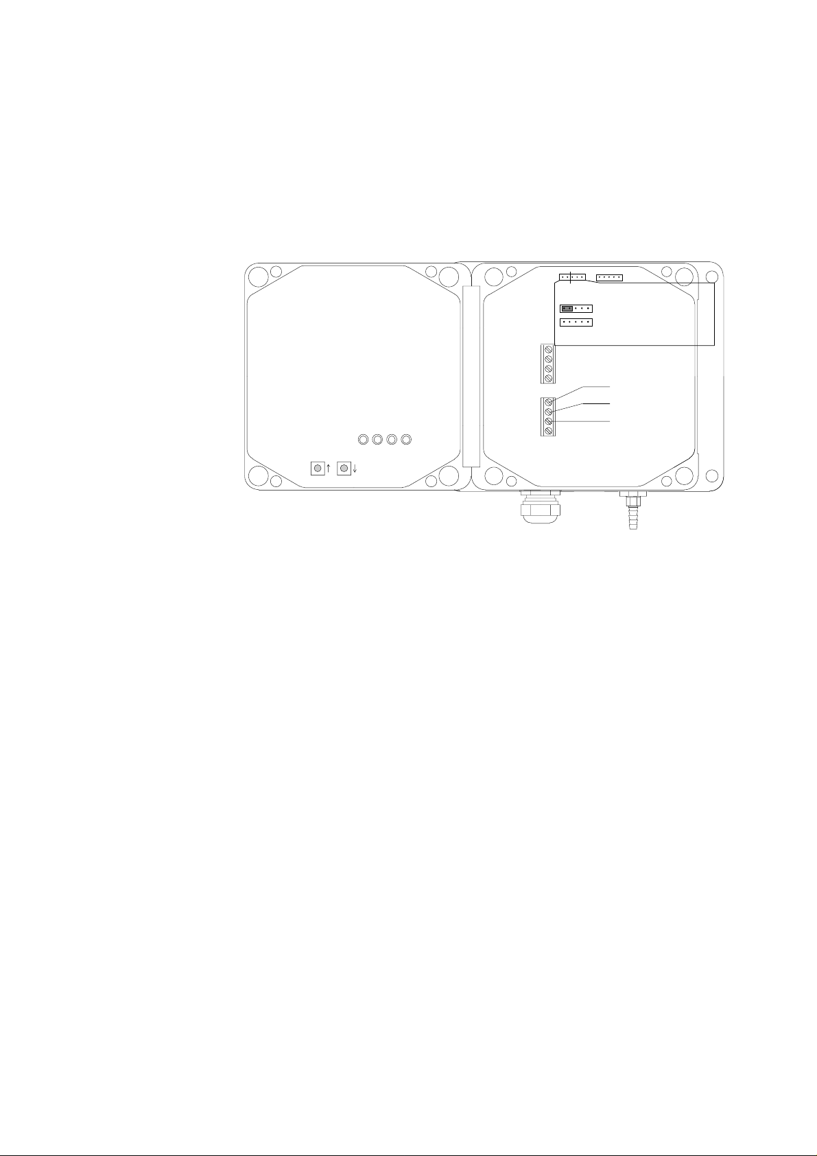
2.3 Power connections
Two wires, one for supply voltage and another for supply ground, are
needed to connect power to the barometer (see Fig. 3).
Fig. 3 Power connections and jumpers
However, when a logic output is available in the host system, a third
wire can be connected to the power control terminal CTRL to enable
external control of the barometer. The POWER jumper of the barometer
must then be removed (see Fig. 3). The logic high TTL level (5 VDC)
turns the barometer on and logic LOW (0 VDC) turns it off. The CTRL
line can withstand higher logic voltage levels and is protected against
electric discharges. To return to normal operation simply re-insert the
POWER jumper.
Page 7
PTB 200 6 (28)
GND
RX
TX
RS 232C TTL TTL INVERT
Digital Barometers
SSD/Operating Manual 24th February 1993 PTB200-O0284-1.1
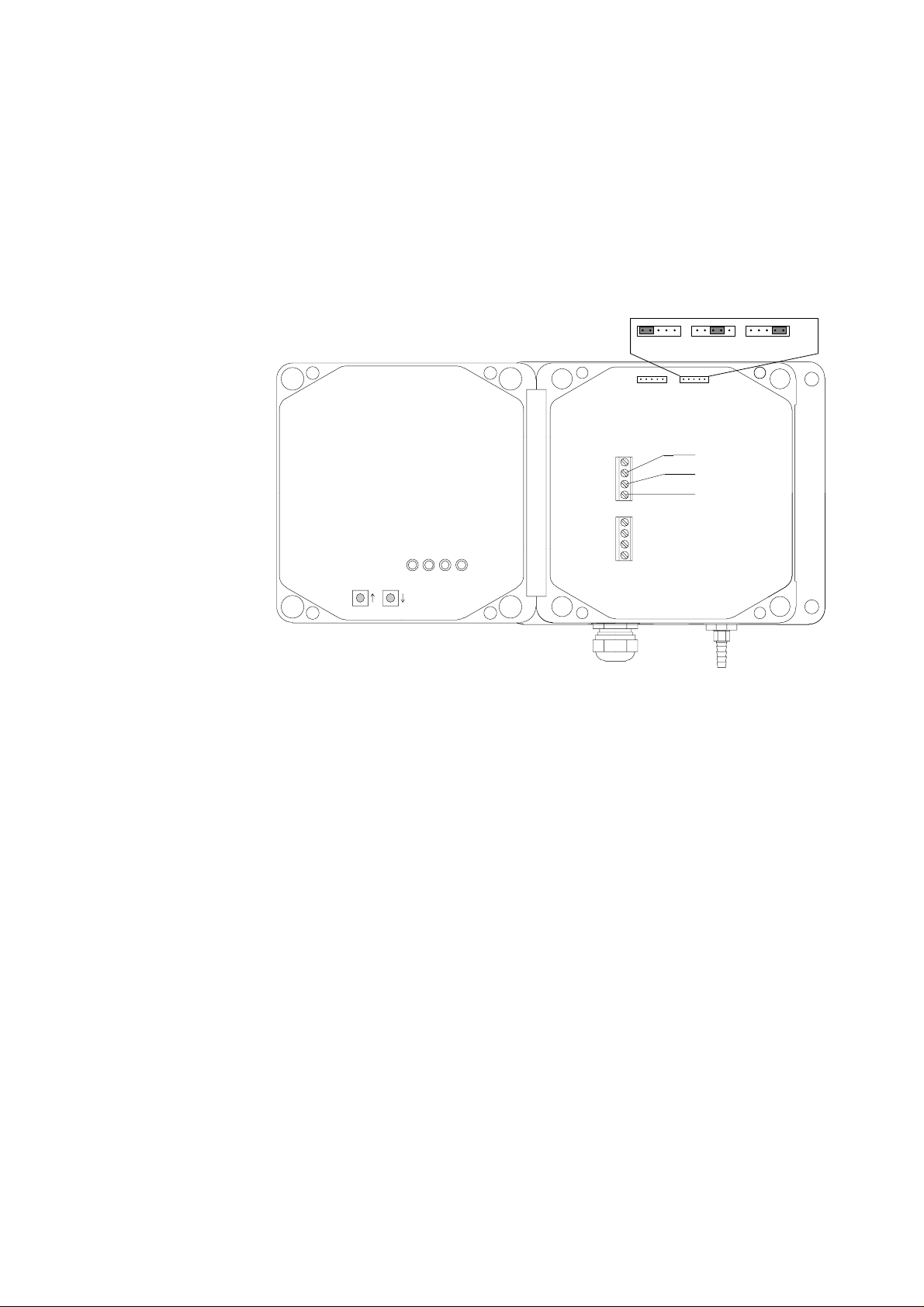
2.4 Serial output mode connections
The serial communication can take place either using RS 232C or TTL
level signals. In both cases the barometer is connected to the host
system with three wires (TX, GND, RX) (see Figure 4). No handshaking
lines are used.
Fig. 4 Serial bus connections and jumpers
The selection between the RS 232C and TTL level output signals is
made with a jumper (see Fig. 4). The TTL level output signal has two
phase alternatives: TTL and TTL INVERT. The TTL output is in phase
with the TXD line of the Intel 8051 microprocessor and the TTL INVERT
output is in phase with the RS 232C output.
Although the PTB 200 barometers use a single polarity supply, both
positive and negative voltage levels occur in the output in the RS 232C
output mode. The higher the supply voltage, the higher are the output
voltages in the transmission line of the barometer; for example, at 12
VDC supply voltage the output voltage levels are approximately ± 8
VDC. The TTL level output voltages are 0 and 5 VDC.
If the supply voltage is raised and the baud rate lowered, the RS 232C
interface can be used over far longer distances than specified for the
standard RS 232C interface.
The receiving RX line accepts both RS 232C and TTL level voltages as
input; the TTL level phase selection does not affect the receiving line of
the barometer.
Page 8

PTB 200 7 (28)
SERIAL OUTPUT
MODE SELECT
PULSE OUTPUT
MODE SELECT
LEDS
GND
PULSE TRIG
PULSE
RS 232C TTL TTL INVERT
PUSH BUTTONS:
Digital Barometers
SSD/Operating Manual 24th February 1993 PTB200-O0284-1.1
2.5 Pulse output mode connections (software version 1.05 or higher)
The pulse output mode uses the same terminals as the serial output
mode (see Figure 5). The transmitting terminal sends the pulse output
(TX/PULSE) and the receiving terminal of the barometer receives the
positive trigger signal (RX/PULSE TRIG).
Fig. 5 Pulse output connections, jumpers and push buttons
The pulse output mode must be separately selected. Two push buttons
(Fig. 5), arrow up and arrow down, are used to switch between the
pulse output mode and the serial output mode.
To select the PULSE OUTPUT operation mode:
1. Set the baud rate to 9600 (see SERI command).
2. Switch power off.
3. Press and keep down the arrow down push button.
4. Switch power on; the four LEDs go on and go out.
5. Release the push button; the LEDs go on and go out again.
To select the SERIAL OUTPUT operation mode:
1. Switch power off.
2. Press and keep down the arrow up push button.
3. Switch power on; the four LEDs go on and go out.
4. Release the push button; the LEDs go on and go out again.
5. Check the serial bus settings (see SERI command).
Page 9

PTB 200 8 (28)
Digital Barometers
SSD/Operating Manual 24th February 1993 PTB200-O0284-1.1
The pulse frequency is about 4.5 kHz at baud rate 9600. The pulse
output is triggered using a positive pulse (e.g. 100 ms/5 VDC). The
pulse output voltage levels can be either RS 232C levels or TTL levels.
The selection is made with a jumper (Fig. 5).
The pressure resolution is limited in the pulse output mode to 0.1 hPa.
Each pulse represents 0.1 hPa, e.g. 10000 pulses equal 1000.0 hPa.
2.6 Pressure connections
The barometer is equipped with a standard Clippard barbed pressure
fitting with 10-32 external thread installed in the barometer. This fitting
is ideal for an 1/8" internal diameter tubing.
If some other pressure fitting needs to be used, it is possible to replace
the barbed fitting. The pressure connection in the barometer housing
has a metric M5 internal thread which is in practice compatible with
non-metric 10-32 internal thread.
The barbed pressure fitting is not recommended for turbulent or high
speed static wind conditions: the accuracy quoted for the PTB 200
digital barometers does not include any wind effects.
The PTB 200 barometers are designed to measure the pressure of
clean, non-condensating, non-conducting and non-corrosive gases
only.
Page 10

PTB 200 9 (28)
GND
GND
TX
RX
RX
GND
TX
RX
GND
TX
BAROMETER 1
BAROMETER 1
BAROMETER 3
RX
TX
HOST
COMPUTER
Digital Barometers
SSD/Operating Manual 24th February 1993 PTB200-O0284-1.1
2.7 Multiple transmitters on one RS 232C bus
It is possible to connect up to 99 PTB 200 barometers to one RS 232C
bus by using a connector box with diodes for each barometer
transmission line and one common barometer receiving line and ground
line (see Figure 6). Each barometer must be initialized to POLL mode
with a specific address (1...99) (see ADDR, SMODE POLL, OPEN and
CLOSE commands). The host computer must have sufficient buffering
to be able to handle several barometers.
Fig. 6 Connector box for several barometers on one RS 232C
bus
Page 11

PTB 200 10 (28)
Digital Barometers
SSD/Operating Manual 24th February 1993 PTB200-O0284-1.1
3 SERIAL COMMANDS
3.1 General
When delivered from factory the barometers are in serial full duplex RS
232C mode. No handshaking lines are in use. All commands are
echoed. The factory settings of the serial bus are:
baud rate 1200
parity even
data bits 7
stop bits 1
echo ON
sending mode STOP
address 0
The following table briefly shows the configuration commands used to
change the settings of the PTB 200 barometers.
Function Command Comment
serial bus settings SERI
echo on/off ECHO
output format FORM
pressure resolution FORM
units UNIT
integration time MTIM, FILT
settling time, response
time
sending mode SMODE STOP, RUN and POLL
address ADDR for POLL mode only
single output command SCOM in STOP and RUN modes
sleep mode SLEEP
list of software settings ?
MTIM, FILT
modes
only
The default output format, pressure resolution and pressure unit have
been set to fit meteorological requirements. The internal time constants
of the barometers have been chosen to prioritize short settling time
(PTB 200 A: 2 s, PTB 201 A: 1 s) and high pressure resolution (PTB
200 A: 0.01 hPa, PTB 201 A: 0.1 hPa). If longer settling time can be
accepted, use longer integration time to suppress noise effects.
Page 12

PTB 200 11 (28)
Digital Barometers
SSD/Operating Manual 24th February 1993 PTB200-O0284-1.1
The PTB 200 barometers have three sending modes: STOP, RUN and
POLL modes. In STOP mode (factory setting) after power-up the
barometer outputs its type code and software version number and then
waits for further commands. In RUN mode pressure output starts
automatically from power-up. POLL mode is meant mainly for
adjustment and calibration where several barometers are connected to
one RS 232C bus.
The following table briefly shows the commands used to control the
operation of the PTB 200 barometers:
Command Comment
starting output R
stopping output S
output single reading SEND address required in POLL
mode
setting output interval INTV
control of a single barometer
in POLL mode
resetting RESET
error messages ERRS
OPEN,
CLOSE
in POLL mode only
The commands are not case sensitive. However, the pressure unit must
be given in the format given at the UNIT command (see UNIT
command).
3.2 Configuration commands
SERI Serial bus settings
SERI b p d s<cr>
where
b baud rate (300, 600, 1200*, 2400, 4800, 9600)
p parity (E=even*,O=odd,N=none)
d data bits (7* or 8)
s stop bits (1* or 2) (* factory settings)
<cr> carriage return is generated by the ENTER or RETURN key of
the host computer
The SERI command is used to set or inspect the serial bus settings.
Page 13

PTB 200 12 (28)
Digital Barometers
SSD/Operating Manual 24th February 1993 PTB200-O0284-1.1
Examples:
>SERI<cr>
1200 E 7 1
>SERI 9600 E 7 1<cr>
9600 E 7 1
>RESET<cr>
>SERI 1200<cr>
1200 E 7 1
>RESET<cr>
Always give the RESET command after the SERI command to invoke
the new serial bus settings.
The following bus settings do not work with the barometer’s Intel 8051
microprocessor and are modified by the barometer:
N 7 1 ⇒ N 7 2
E 8 2 ⇒ E 8 1
O 8 2 ⇒ O 8 1
Note: N 7 2 works on software version 1.06 or higher only.
The following settings can not be used at all:
E 8 1, O 8 1
ECHO Setting the serial bus echo on/off
ECHO ON<cr>
ECHO OFF<cr>
The ECHO command is used to control serial bus echo. In OFF mode
the barometer does not output the ’>’ prompt character.
FORM Defining the output format
FORM<cr>
The FORM command is used to define the desired format and pressure
resolution of the output. Do not use the FORM command to select a
pressure unit (instead see UNIT command).
Page 14

PTB 200 13 (28)
Digital Barometers
SSD/Operating Manual 24th February 1993 PTB200-O0284-1.1
The basic definition consists of the current and new format:
>FORM<cr>
(current output format appears here)
? (type new format here)<cr>
The output format consists of the pressure reading area, pressure unit
area, carriage return and line feed, e.g.:
"\PPPP.PP\ \uuuu\\r\n"
where
\PPPP.PP\ pressure reading area
\uuuu\ pressure unit area
\r carriage return
\n line feed
An example of changing the output pressure resolution from two to one
decimal (0.01 ⇒ 0.1):
>FORM<cr>
"\PPPP.PP\ \uuuu\\r\n"
? \PPPP.P\ \uuuu\\r\n<cr>
Example of adding leading spaces:
>FORM<cr>
"\PP.PPP\ \uuuu\\r\n"
? \PPPP.PPP\ \uuuu\\r\n<cr>
Example of adding text to the output:
>FORM<cr>
"\PPPP.PP\ \uuuu\\r\n"
? Barometric pressure = \PPPP.PP\ \uuuu\\r\n<cr>
Example of omitting the pressure unit from the output:
>FORM<cr>
"\PPPP.PP\ \uuuu\\r\n"
? \PPPP.PP\\r\n<cr>
Page 15

PTB 200 14 (28)
Digital Barometers
SSD/Operating Manual 24th February 1993 PTB200-O0284-1.1
UNIT Setting the pressure unit
UNIT x<cr>
where
x hPa*, kPa, mbar, inHg, mmHg, torr, psia (* factory setting).
Command UNIT is used to select the pressure unit. Type the selected
pressure unit as given above.
Example of changing the pressure unit to mbar:
>UNIT mbar<cr>
MTIM Setting the measurement time parameters
MTIM<cr>
The MTIM command is used to set the number of measurement samples (MTIM value) integrated to get a pressure reading. The basic
measurement sample time is about 25 milliseconds. The MTIM value
can range from 4 to 255.
The MTIM factory setting of the PTB 200 A is 64; this ensures a stable
resolution of 0.01 hPa. The integration time is then 64 x 25 ms = 1600
ms. The settling time including initialization and integration time is approximately 2 s.
The MTIM factory setting of the PTB 201 A is 16; this ensures a stable
resolution of 0.1 hPa. The integration time is then 16 x 25 ms = 400 ms.
The settling time including initialization and integration time is approximately 1 s.
The MTIM value affects the settling time of the barometer: the longer
the integration time, the longer the settling time.
The FILT command also affects the integration and settling times (see
FILT command).
Example of changing the MTIM value:
>MTIM<cr>
Mtim : 64 ? 150<cr>
Page 16

PTB 200 15 (28)
Digital Barometers
SSD/Operating Manual 24th February 1993 PTB200-O0284-1.1
FILT Setting the filter parameters
FILT xxx yyyy<cr>
where
xxx ON or OFF
yyyy FAST or SLOW
The FILT command is used to set additional numerical filtering modes.
FAST mode introduces a multiplication factor of 4 to the integration time
set with the MTIM command. In addition a special algorithm that takes
the derivative of the pressure change into account is used.
SLOW mode introduces a multiplication factor of 16 to the integration
time set with the MTIM command. No derivative of the pressure change
is taken into account.
The filter settings also affect the settling time of the barometer.
Example of setting the integration time to 5 seconds (MTIM 50, filter
FAST):
>MTIM<cr>
Mtim : 64 ? 50<cr>
>FILT ON FAST<cr>
Press. filter : ON
FAST
Example of setting the integration time to 60 seconds (MTIM 150, filter
SLOW):
>MTIM<cr>
Mtim : 50 ? 150<cr>
>FILT ON SLOW<cr>
Press. filter : ON
SLOW
>FILT OFF<cr>
turns the filter mode off. Then only the MTIM command affects the integration and settling times.
Page 17

PTB 200 16 (28)
Digital Barometers
SSD/Operating Manual 24th February 1993 PTB200-O0284-1.1
SMODE Setting the sending mode
SMODE xxxx<cr> STOP and RUN modes only
SMODE aa STOP<cr> POLL mode only
where
xxxx STOP, RUN or POLL
aa the address (1...99) of the barometer in the POLL mode
SMODE command sets or inspects the sending mode of the barometer.
The factory setting is the STOP mode. After power-up or reset the ba-
rometer outputs only its type code and software version number;
pressure readings are output only by command.
In the RUN mode the barometer starts to output pressure readings
automatically after power-up or reset. The S command can be used to
stop the output.
The POLL mode is used mainly during adjustment and calibration when
several barometers are connected to one RS 232C bus. In the POLL
mode measurements can be output only with SEND aa command (see
SEND aa command). Echo is off in the POLL mode. See also OPEN
and CLOSE commands for further details on how to control a single
barometer when several barometers are connected on one RS 232C
bus.
Example of setting, using and resetting the POLL mode:
>SMODE<cr>
Serial mode : STOP
>ADDR<cr>
Address : 0 ? 7<cr>
>SMODE POLL<cr>
Serial mode : POLL
SEND 7<cr>
(pressure reading appears here)
SMODE 7 STOP<cr>
Serial mode : STOP
>ADDR<cr>
Address : 7 ? 0<cr>
Page 18

PTB 200 17 (28)
Digital Barometers
SSD/Operating Manual 24th February 1993 PTB200-O0284-1.1
ADDR Setting the barometer address (for POLL mode only)
ADDR<cr>
ADDR is used to set or inspect an address (1...99) of a barometer for
the POLL mode.
Example of setting the address 7:
>ADDR<cr>
Address : 0 ? 7<cr>
A new address replaces the previous address. Always set the address
to 0 when no address is needed:
>ADDR
Address : 7 ? 0<cr>
If the barometer is not in the POLL mode, it will respond to any SEND
command regardless of if there is an address or not. See SMODE and
SEND commands for further details.
SCOM Setting a user defined command for single reading
output (STOP and RUN modes only)
SCOM<cr>
is used to define a new command for single reading output in the STOP
and RUN modes. A command defined by SCOM command does not
work in the POLL mode. The SEND command is always available.
Example of a command definition:
>SCOM P<cr>
>P<cr>
(a single pressure reading appears)
A new SCOM command replaces the previous definition.
Page 19

PTB 200 18 (28)
Digital Barometers
SSD/Operating Manual 24th February 1993 PTB200-O0284-1.1
SLEEP Setting and resetting the sleep mode
SLEEP ON<cr>
SLEEP OFF<cr>
The SLEEP command is used to set and reset the software controlled
sleep mode which cuts down the power consumption by over 60 %. In
the sleep mode the current consumption is below 10 mA when no output is required and about 25 mA during output. By activating the sleep
mode the barometer automatically falls asleep when no output is
required. Even then the barometer is ready to accept commands and
execute them. However, because the barometer needs to wake up, the
time from a command to output is a bit longer in SLEEP mode than in
normal mode.
? List of basic software settings
?<cr>
Entering ? outputs a list of basic software settings, e.g.
Baud Parity Data Stop 1200 E 7 1
Output format \PPPP.PP\ \uuuu\\r\n
Pressure unit hPa
Temperature unit ’C
Sending mode STOP
Address 0
Sleep mode OFF
Measurement time 64 x 25 milliseconds
Filter OFF / FAST
Output interval 0 s
Calibration day code 92261
Offset drift comp. ON
Offset drift correction -0.056 hPa
Multipoint correction ON
Reading Correction
499.64 0.024
599.79 0.013
699.92 0.017
800.04 0.021
900.18 0 017
1000.33 0.023
1100.43 0.027
Page 20

PTB 200 19 (28)
Digital Barometers
SSD/Operating Manual 24th February 1993 PTB200-O0284-1.1
3.3 Operating commands
R Starting the measurement output
R<cr>
Command R starts the measurement output. The command is used to
start output in the STOP and RUN modes (see SMODE command) and
in interval output mode (see INTV command).
S Stopping the measurement output
S<cr>
Command S ends the RUN mode.
SEND Output a single reading
SEND<cr> STOP and RUN modes only
SEND aa<cr> POLL mode only
where
aa the address of the barometer (0...99)
SEND command is used to output one pressure reading.
See also SCOM command to define your own command for single
reading output in the STOP and RUN modes.
INTV Setting the output interval
INTV xxx yyy<cr>
where
xxx output interval (0...255)
yyy unit (s, min, h)
INTV command selects the interval output mode and sets the desired
output interval. The R command is used to start the interval outputting.
Page 21

PTB 200 20 (28)
Digital Barometers
SSD/Operating Manual 24th February 1993 PTB200-O0284-1.1
Example of outputting the current settings:
>INTV<cr>
Output intrv. : 0 s
Example of setting an output interval and starting outputting:
>INTV 1 min<cr>
Output intrv. : 1 min
>R<cr>
Example of cancelling the interval output mode:
>INTV 0 s<cr>
Output intrv. : 0 s
OPEN Setting a barometer to STOP mode (POLL mode only,
CLOSE software version 1.04 or higher)
OPEN aa<cr>
CLOSE aa<cr>
where
aa the address (1 ... 99) of the barometer
OPEN and CLOSE commands are used to set a barometer momentarily to STOP mode and back to POLL mode again. This command is
very useful when several barometers are connected to one RS 232C
bus and only one individual barometer needs to be contacted.
Example of communication with a barometer with address 7:
>OPEN 7<cr>
PTB 7 bus opened for operator commands
(normal commands can now be used without disturbing other
barometers on the RS 232C bus)
>CLOSE 7<cr>
bus closed
(the barometer with address 7 is set back to the POLL mode and
only SEND 7 and SMODE 7 STOP commands work)
Please note that when leaving the POLL mode, command CLOSE must
always be followed by the address of the barometer.
Page 22

PTB 200 21 (28)
Digital Barometers
SSD/Operating Manual 24th February 1993 PTB200-O0284-1.1
RESET Resetting the barometer
RESET<cr>
resets the barometer. All software settings remain in the memory after
reset or any power failure. After changing the serial bus settings
RESET must always be given to invoke them.
ERRS Error message output
ERRS<cr>
ERRS command is used to print the error messages if any problems
occur. The command outputs an error code and error description:
>ERRS<cr>
E51 P y-value out of range
When an error occurs in the barometer, give the following seven commands and print the responses on paper. On the basis of the responses to these commands Vaisala can quickly determine which actions to take. The commands are:
>ERRS<cr>
>?<cr>
>C<cr>
>F<cr>
>T<cr>
>Y<cr>
>L<cr>
Page 23

PTB 200 22 (28)
MEMORY JUMPER
write disable
write enable
Digital Barometers
SSD/Operating Manual 24th February 1993 PTB200-O0284-1.1
4 ADJUSTMENT AND CALIBRATION
The PTB 200 barometers can be adjusted and calibrated against local
primary standards that have high accuracy and stability as well as
known traceability to international standards.
The PTB 200 barometers are recommended to be adjusted or
calibrated once a year when used in automatic weather station applications. In very demanding pressure standard applications shorter adjustment or calibration periods, e.g. two to four times a year, can be
chosen.
The user can not erase the basic pressure and temperature adjustment
coefficients made at factory from the barometer’s memory. If anything
goes wrong with adjustments or calibration, the user can always revert
to the basic factory settings by changing the MEMORY jumper to
EEPROM write enable position and then giving the following
commands:
>LIP<cr>
P offset 0 * 0.001 ? 0<cr>
P gain 0 * 0.00001 ? 0<cr>
>MPC OFF<cr>
Multip. corr. : OFF
The factory settings can be changed only when the MEMORY jumper is
in the EEPROM write enable position (see Fig. 7).
Fig. 7 MEMORY jumper positions
Page 24

PTB 200 23 (28)
Digital Barometers
SSD/Operating Manual 24th February 1993 PTB200-O0284-1.1
The following pressure adjustments are possible:
• offset adjustment
• offset/gain adjustment
• multipoint adjustment at up to eight pressure levels.
Offset and offset/gain adjustments are made with the barometer
connected to a reference pressure (see LP command). With the LP
command the pressure value of the primary standard is given to the barometer as a reference pressure and no separate corrections are
needed.
Before multipoint adjustment, the barometer must first be precalibrated
in order to find out the corrections needed to bring the barometer to the
accuracy level of the primary standard. After precalibration the
multipoint corrections are entered through the serial interface (see MPC
and MPCI commands).
Note that up to 99 PTB 200 barometers can be connected to one RS
232C bus which makes their adjustment and calibration more cost
effective.
4.1 Offset and gain adjustment
LP Linear pressure adjustments
LP<cr>
The LP command is used in offset and offset/gain adjustment of the
barometer.
The offset adjustment can be made at any pressure level. To guarantee
the best possible pressure stability connect the pressure port of the
barometer to the pressure standard even during offset adjustment. The
two pressure levels used in offset/gain adjustment must be at least 400
hPa apart.
Change the MEMORY jumper to the EEPROM write enable position.
Example of an offset adjustment:
>LP<cr>
Ref1 ? (set pressure level and enter value
here)<cr>
P : (the current non-corrected value
appears here)
Ref2 ? <cr>
Page 25

PTB 200 24 (28)
Digital Barometers
SSD/Operating Manual 24th February 1993 PTB200-O0284-1.1
Example of an offset and gain adjustment:
>LP<cr>
Ref1 ? (set first pressure level and enter value
here)<cr>
P : (the current non-corrected value
appears here)
Ref2 ? (set second pressure level and enter
value here)<cr>
P : (the current non-corrected value
appears here)
Use ESC to abort without executing a command.
Return the MEMORY jumper to the EEPROM write disable position.
4.2 Multipoint pressure adjustment
MPC OFF Multipoint correction off
MPCI Multipoint correction input
MPC ON Multipoint correction on
MPC OFF<cr>
MPCI<cr>
MPC ON<cr>
The MPC/MPCI commands are used in multipoint pressure adjustment
at up to eight pressure levels.
If a new fine adjustment is needed, the previous multipoint corrections
must first be omitted with the MPC OFF command. Writing down the
previous multipoint corrections is recommended as they will be lost
when MPCI command is used. Precalibrate the barometer to find out
the new multipoint corrections; the corrections are then entered using
the MPCI command. The MPC ON command is used to activate the
new corrections.
Change the MEMORY jumper to the EEPROM write enable position.
Example of the multipoint pressure correction procedure:
>LIP<cr>
P offset 0 * 0.001 ? 0<cr>
P gain 0 * 0.00001 ? 0<cr>
>MPC OFF <cr>
Multip. corr. : OFF
Page 26

PTB 200 25 (28)
Digital Barometers
SSD/Operating Manual 24th February 1993 PTB200-O0284-1.1
First precalibrate the barometer at up to eight pressure levels. Then
calculate the corrections (reference value minus PTB 200 barometer
indication) at each pressure level and enter the corrections using the
MPCI commands.
>MPCI<cr>
1. PTB reading ?499.64<cr>
correction ?0.024<cr>
2. PTB reading ?599.79<cr>
correction ?0.013<cr>
...
7. PTB reading ?1100.33<cr>
correction ?0.027<cr>
8. PTB reading ?<cr>
>MPC ON <cr>
Multip. corr. : ON
Reading Corrections
499.6400 0.0240
599.7900 0.0130
..
..
..
1100.3300 0.0270
Use ESC to abort without executing a command.
Return the MEMORY jumper to the EEPROM write disable position.
Page 27

PTB 200 26 (28)
Digital Barometers
SSD/Operating Manual 24th February 1993 PTB200-O0284-1.1
5 TECHNICAL DATA
OPERATING RANGE
Pressure range 600 ... 1100 hPa
Operating temperature range -40 °C ... +60 °C
Storage temperature range -60 °C ... +60 °C
Humidity range non-condensing
Note: 1 hPa = 1 mbar (see note below).
ACCURACY PTB 200 A PTB 201 A
Linearity * ±0.05 hPa
±0.10 hPa
1)
2)
±0.15 hPa
Hysteresis * ±0.03 hPa ±0.03 hPa
Repeatability * ±0.03 hPa ±0.03 hPa
Calibration uncertainty ** ±0.10 hPa ±0.20 hPa
Accuracy at +20 °C ***
±0.12 hPa
±0.15 hPa
1)
2)
±0.25 hPa
Temperature dependence ±0.1 hPa ±0.1 hPa
Total accuracy (RSS) ±0.20 hPa ±0.3 hPa
Long-term stability ±0.1 hPa / a +0.2 hPa / a
* Defined as the ±2 standard deviation limits of end-point non-
linearity, hysteresis error or repeatability error.
** Defined as ±2 standard deviation limits of inaccuracy of the pri-
mary or working standard at 1000 hPa in comparison to international standards (NIST).
*** Defined as the root sum of the squares (RSS) of end-point non-
linearity, hysteresis error, repeatability error and calibration uncertainty at room temperature.
1) 800 to 1100 hPa
2) 600 to 1100 hPa
Note. The unit hectopascal (hPa) is recommended by WMO to be
used in meteorological barometric pressure measurement (see
WMO Guide to Meteorological Instruments and Methods of Observation, Fifth edition, 1983).
The official unit of pressure is pascal (Pa) and its multiples
according to the International System of Units (SI) and
according to ISO 1000.
Page 28

PTB 200 27 (28)
Digital Barometers
SSD/Operating Manual 24th February 1993 PTB200-O0284-1.1
GENERAL CHARACTERISTICS (factory settings*)
Supply voltage 10 ... 30 VDC, polarity protected
Supply voltage sensitivity negligible
Current consumption < 25 mA
< 10 mA (sleep mode)
< 0.1 mA (shutdown mode)
Serial I/O RS 232C* full duplex serial I/O or
bidirectional TTL level serial I/O
code ASCII
parity even*, odd, none
data bits 7* or 8
stop bits 1* or 2
Pulse output pulse output at about 4.5 kHz;
10.000 pulses = 1000.0 hPa
Pressure units hPa*, kPa, mbar, inHg, mmHg,
torr, psia
Baud rates 300, 600, 1200*, 2400, 4800,
9600
Resolution
PTB 200 A 0.01 hPa*
PTB 201 A 0.1 hPa*
Settling time after power-up
PTB 200 A 2 seconds*
PTB 201 A 1 second*
Pressure step response time
PTB 200 A 500 ms*
PTB 201 A 300 ms*
Acceleration sensitivity negligible
Pressure connection M5 (10-32) internal thread
Pressure fitting barbed tube for 1/8" I.D. tubing
Maximum pressure limit 5000 hPa abs.
Minimum pressure limit 0 hPa abs.
Cable bushing for 5 ... 10 mm diameter cables
Electrical connections
excitation supply, GND, CTRL (for
shutdown)
serial communication TX, RX, GND
pulse output PULSE, PULSE TRIG, GND
Electrical connectors screw terminals for AWG 22...16
wire
Housing epoxy painted aluminium
Weight 950 g
Page 29

PTB 200 28 (28)
Digital Barometers
SSD/Operating Manual 24th February 1993 PTB200-O0284-1.1
Dimensions in mm (inches)
145 (5.71)
133 (5.24)
120 (4.72)
Ø 6.5 (0.26)
65 (2.56)
27.5 (1.08)
104 (4.09)
120 (4.72)
139.5 (5.49)
Page 30

PTB200 Digital Barometer
SERIAL COMMANDS
Function Command Comment
serial bus settings SERI
echo on/off ECHO
output format FORM
pressure resolution FORM
units UNIT
integration time MTIM, FILT
settling time/response time MTIM, FILT
sending mode SMODE STOP, RUN and POLL modes
address ADDR for POLL mode only
defining single output
command
sleep mode SLEEP
list of software settings ?
SCOM in STOP and RUN modes
only
Appendix 1
starting output R
stopping output S
output single reading SEND in POLL mode address
required
setting output interval INTV
control of a single barometer
OPEN ,CLOSE
in POLL mode
resetting RESET
error messages ERRS
linear pressure adjustment LP
multipoint correction MPC, MPCI
1994-08-16 1
 Loading...