How it Works
Log In / Sign Up
Buy Points
How it Works
FAQ
Contact Us
Questions and Suggestions
Users
Vaisala
Loading...
L
LS7001
LT31
M
M211518
M212315EN-B
M212315PT-B
MAWS100
MAWS101
MAWS110
MAWS201
MAWS201M
MAWS201MP TACMET
MAWS301
MAWS410
4
MDSS
2
MGP260
MGP261
MHT410
2
MI70
MI70LINK
MITRAS
MM70
6
MMP8
2
MMT162
4
MMT310
3
MMT330
11
MOG100
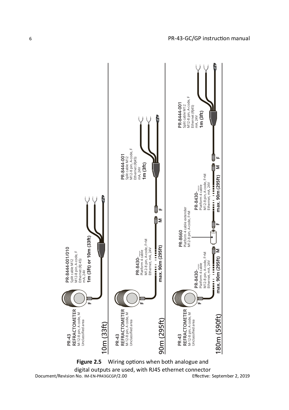
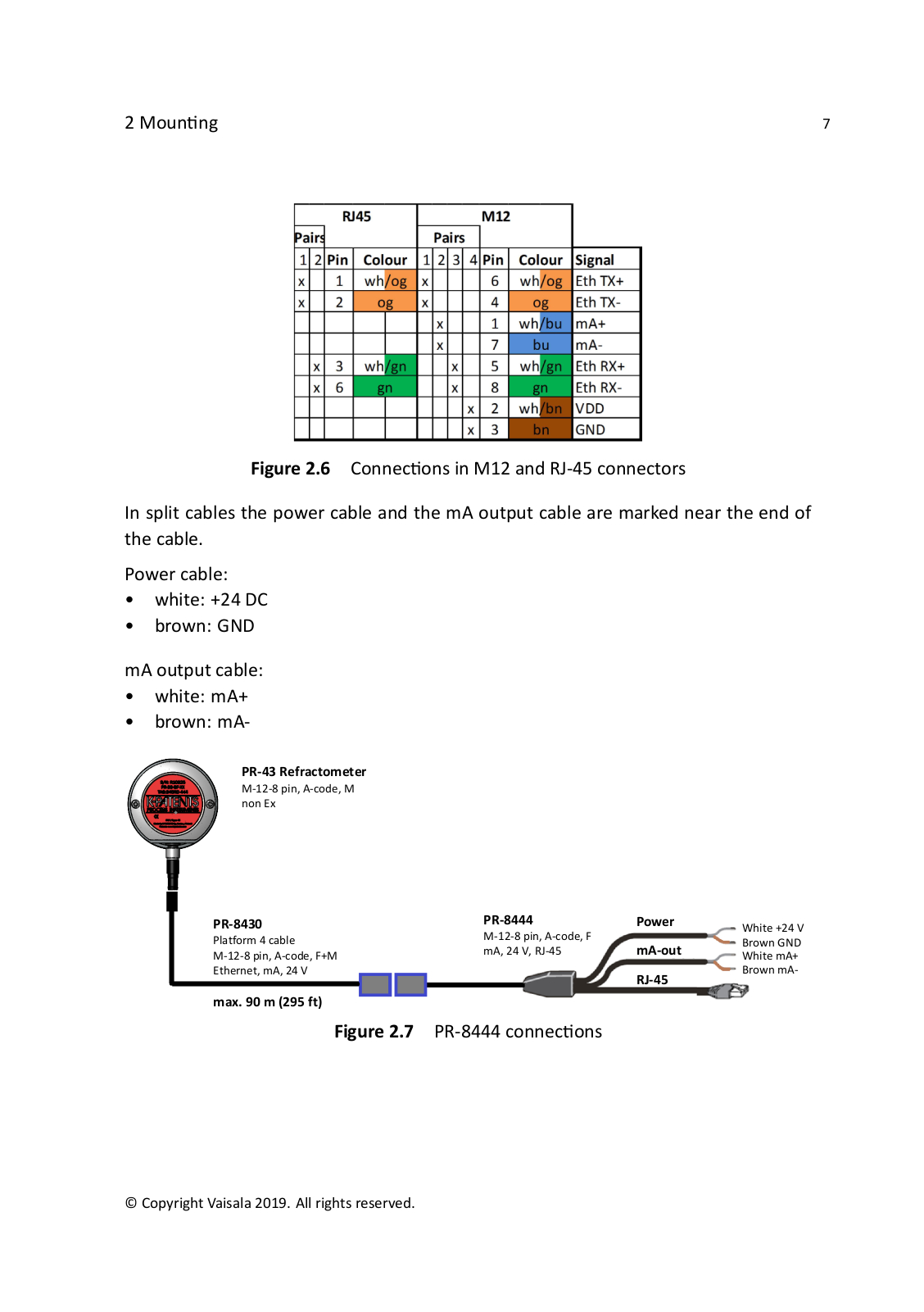
MOUNTING
MW11
MW12
MW15
MW31
3
MW32
2
MW41
N
NPEP
2
O
Observation Display
OBSERVER
OMT355
3
OMT364
3
OPT100
2
Optimus OPT100
3
P
PDT101
4
PDT102
4
PMB100
2
POWER-1
PR-23
4
PR-33
PR-33-AC
PR-43
PR-43-AC
PR-43-AP
PR-43-GC
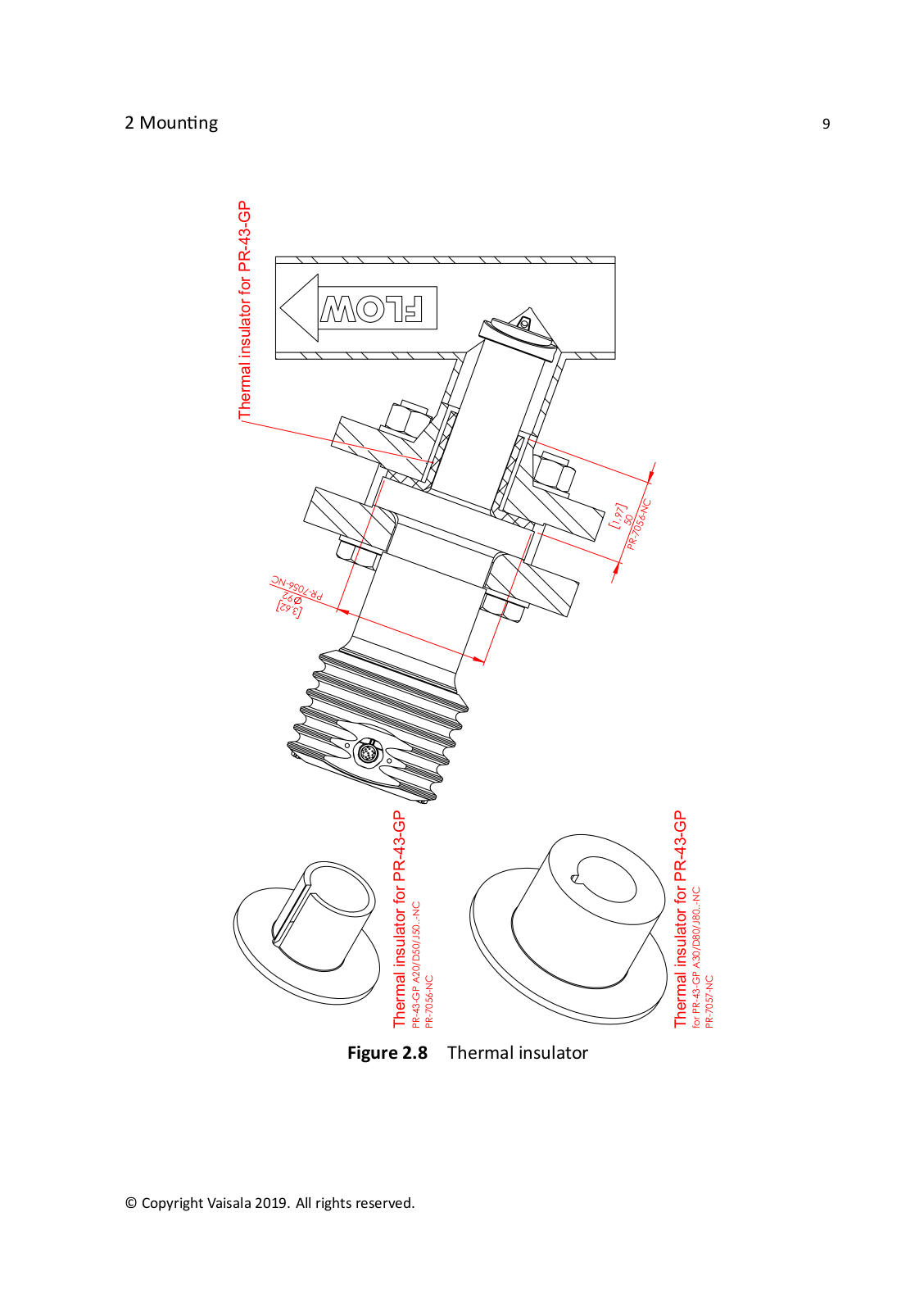
PR-43-GP
PTB100
PTB110
3
PTB200
PTB210
7
PTB210MDSS
PTB220
3
PTB220AxB2Ax
PTB220Case
PTB220 Series
PTB220TS
2
PTB220TS / CASE
PTB330
6
PTB330TS
4
PTU200
2
PTU200MIK1
PTU200 series
PTU300
8
PTU301
PWD10
PWD12
PWD20
PWD22
2
PWD50
PWD52
Q
QMD202
QML201C
QMT103
QMT110
R
RADARS METEOROLOGIQUES
Radiosonde RS92-SGP
RD93
RD94
RDP100
Remote Divert
RFL100
4
RG13
RG13H
RM32
2
RS41
RS41-SG
RS41-SGP
2
RS92-AM
RS92-D
2
RS92-K
RS92-KL
2
RS92-SGP
6
RSA921
RSA922
Loading...
Loading...
Nothing found
PR-43-GC
Users guide
48 pgs
12.45 Mb
0
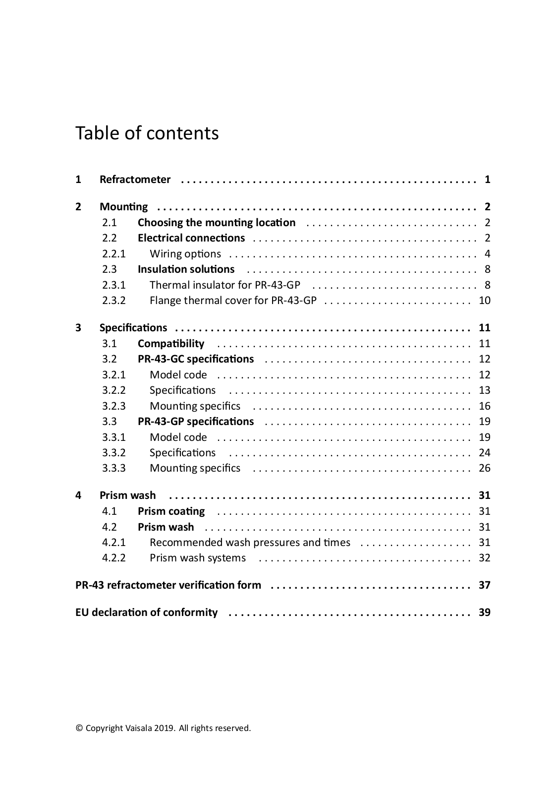
Table of contents
Loading...
Vaisala PR-43-GC, PR-43-GP Users guide
...
Vaisala Users guide
Download
Specifications and Main Features
Frequently Asked Questions
User Manual
Download
Loading...
+
hidden pages
Unhide
You need points to download manuals.
1 point = 1 manual.
You can buy points or you can get point for every manual you upload.
Buy points
Upload your manuals
 Loading...