

Page 1

IM-EN-PR23-E
User Guide
Process Refractometer
PR-23 Series
Page 2

PUBLISHED BY
Vaisala Oyj
Vanha Nurmijärventie 21, FI-01670 Vantaa, Finland
P.O. Box 26, FI-00421 Helsinki, Finland
+358 9 8949 1
Visit our Internet pages at www.vaisala.com.
© Vaisala 2021
No part of this document may be reproduced,
published or publicly displayed in any form or by
any means, electronic or mechanical (including
photocopying), nor may its contents be modified,
translated, adapted, sold or disclosed to a third
party without prior written permission of the
copyright holder. Translated documents and
translated portions of multilingual documents are
based on the original English versions. In
ambiguous cases, the English versions are
applicable, not the translations.
The contents of this document are subject to
change without prior notice.
Local rules and regulations may vary and they
shall take precedence over the information
contained in this document. Vaisala makes no
representations on this document’s compliance
with the local rules and regulations applicable at
any given time, and hereby disclaims any and all
responsibilities related thereto.
This document does not create any legally
binding obligations for Vaisala towards customers
or end users. All legally binding obligations and
agreements are included exclusively in the
applicable supply contract or the General
Conditions of Sale and General Conditions of
Service of Vaisala.
This product contains software developed by
Vaisala or third parties. Use of the software is
governed by license terms and conditions
included in the applicable supply contract or, in
the absence of separate license terms and
conditions, by the General License Conditions of
Vaisala Group.
This product may contain open source software
(OSS) components. In the event this product
contains OSS components, then such OSS is
governed by the terms and conditions of the
applicable OSS licenses, and you are bound by the
terms and conditions of such licenses in
connection with your use and distribution of the
OSS in this product. Applicable OSS licenses are
included in the product itself or provided to you
on any other applicable media, depending on
each individual product and the product items
delivered to you.
Page 3

Table of contents
1. About this document...................................................................................... 11
1.1 Version information............................................................................................ 11
1.2 Documentation conventions..............................................................................11
1.3 Trademarks..........................................................................................................12
1.4 Patent notice.......................................................................................................12
2. Product overview.............................................................................................13
2.1 Safety...................................................................................................................13
2.2 Storage conditions, packaging and transportation....................................... 15
2.3 PR-23 refractometer models............................................................................ 15
2.4 Refractometer sensor........................................................................................15
3. Mounting sensor...............................................................................................17
3.1 Choosing sensor mounting location................................................................17
3.2 PR-23 mounting guide...................................................................................... 19
3.3 Pipe mounting checklist...................................................................................20
3.4 Checklist for mounting in tank, vessel or large pipe.................................... 20
4. Indicating transmitter DTR...........................................................................21
4.1 Mounting indicating transmitter..................................................................... 23
4.2 Electrical connections...................................................................................... 24
4.2.1 Interconnecting cable................................................................................ 24
4.2.2 Connecting sensor......................................................................................25
4.2.3 Connecting indicating transmitter............................................................27
4.2.4 Power terminals for AC power..................................................................33
4.2.5 Power terminals for 24 VDC power..........................................................33
4.2.6 Relay connections...................................................................................... 34
4.2.7 Reset button................................................................................................36
Table of contents
5. Prism wash systems....................................................................................... 37
5.1 Prism coating.....................................................................................................37
5.2 Prism wash......................................................................................................... 37
5.2.1 Recommended wash pressures and times..............................................37
5.2.2 Prism wash systems................................................................................... 39
5.2.3 Prism wash nozzles.................................................................................... 46
6. Startup and use...............................................................................................50
6.1 Startup............................................................................................................... 50
6.1.1 Initial check................................................................................................. 50
6.1.2 Calibration check......................................................................................... 51
6.1.3 Testing prism wash...................................................................................... 51
6.2 Using indicating transmitter............................................................................. 51
6.2.1 Keyboard functions.................................................................................... 52
6.2.2 Display setup...............................................................................................53
6.3 Viewing system information............................................................................ 55
6.4 Viewing sensor status.......................................................................................55
6.4.1 Optical image with IDS.............................................................................. 55
6.4.2 Optical image with VD............................................................................... 57
6.4.3 Diagnostic values........................................................................................57
6.4.4 Temperature measurement.......................................................................58
6.4.5 Sensor head humidity................................................................................ 58
6.5 Sensor verification............................................................................................ 58
1
Page 4

PR-23 Series User Guide
7. Configuration and calibration....................................................................59
7.1 Configuring
output signal damping............................................................... 59
7.1.1 Exponential damping.................................................................................59
7.1.2 Linear damping.......................................................................................... 60
7.1.3 Slew rate limit...............................................................................................61
7.2 Configuring output signal hold functionality................................................ 62
7.2.1 External hold............................................................................................... 63
7.2.2 Hold during wash........................................................................................63
7.2.3 Tolerance time.............................................................................................63
7.2.4 QF threshold............................................................................................... 64
7.2.5 Hold source interactions............................................................................64
7.2.6 Hold and signal damping...........................................................................65
7.2.7 Hold functions with DD‑23........................................................................ 65
7.3 Configuring refractometer system................................................................. 66
7.3.1 Configuring relays...................................................................................... 66
7.3.2 Configuring input switches....................................................................... 68
7.3.3 Configuring mA outputs............................................................................70
7.4 Calibrating concentration measurement........................................................72
7.4.1 Chemical curve............................................................................................74
7.4.2 Selecting display units and display decimals..........................................74
7.4.3 Field calibration...........................................................................................75
7.4.4 Entering field calibration parameters...................................................... 76
7.4.5 Direct BIAS adjustment..............................................................................76
7.5 Configuring prism wash................................................................................... 77
7.5.1 Wash cycle...................................................................................................77
7.5.2 Setting prism wash parameters................................................................82
IM-EN-PR23-E
8. Regular maintenance....................................................................................84
8.1 Checking sensor humidity level...................................................................... 84
8.2 Checking prism and prism gaskets.................................................................84
9. Troubleshooting.............................................................................................. 85
9.1 Hardware............................................................................................................85
9.1.1 Blank display............................................................................................... 88
9.1.2 Diagnostic LEDs..........................................................................................89
9.1.3 Display unreadable......................................................................................91
9.1.4 Troubleshooting messages
........................................................................92
9.1.5 Diagnostic message priorities...................................................................97
10. Sensor specifications
.................................................................................... 99
10.1 Sensor compatibility.........................................................................................99
10.2 Sensor rangeability...........................................................................................99
10.3 Sanitary process refractometer PR‑23‑AC...................................................100
10.3.1 PR‑23‑AC sensor model code.................................................................100
10.3.2 PR
‑23‑AC mounting hardware model code...........................................102
10.3.3 PR‑23‑AC specifications.......................................................................... 106
10.3.4 PR‑23‑AC parts list....................................................................................107
10.3.5 PR‑23‑AC mounting specifics..................................................................107
10.3.6 Mounting specifics for EHEDG‑certified PR‑23‑AC configuration....... 112
10.3.7 3‑A Sanitary Standard compliance.......................................................... 112
10.4 Sanitary probe refractometer PR‑23‑AP....................................................... 113
10.4.1 PR‑23‑AP model code............................................................................... 113
10.4.2 PR‑23‑AP mounting hardware model code............................................116
10.4.3 PR‑23‑AP specifications............................................................................118
2
Page 5

10.4.4 PR‑23‑AP parts list..................................................................................... 119
10.4.5 PR‑23‑AP mounting specifics...................................................................119
10.4.6 Mounting specifics for EHEDG‑certified PR‑23‑AP configuration....... 121
10.4.7 3‑A Sanitary Standard compliance.......................................................... 121
10.5 Compact process refractometer PR‑23‑GC..................................................122
10.5.1 PR‑23‑GC sensor model code..................................................................122
10.5.2 PR‑23‑GC specifications...........................................................................124
10.5.3 PR‑23‑GC parts list....................................................................................126
10.5.4 PR‑23‑GC mounting specifications.........................................................126
10.6 Probe process refractometer PR‑23‑GP........................................................ 131
10.6.1 PR‑23‑GP sensor model code..................................................................132
10.6.2 PR‑23‑GP specifications...........................................................................133
10.6.3 PR‑23‑GP thermal cover PR‑7062.......................................................... 134
10.6.4 PR‑23‑GP parts list....................................................................................136
10.6.5 PR‑23‑GP mounting specifications......................................................... 137
10.7 Process refractometer PR‑23‑RP...................................................................138
10.7.1 PR‑23‑RP sensor model code..................................................................139
10.7.2 PR‑23‑RP specifications...........................................................................140
10.7.3 PR‑23‑RP parts list.....................................................................................141
10.7.4 PR‑23‑RP head parts list..........................................................................142
10.7.5 PR‑23‑RP dimensions...............................................................................143
10.7.6 PR‑23‑RP mounting specifications.........................................................144
10.7.7 PR‑23‑RP prism wash system..................................................................145
10.8 Teflon body refractometer PR‑23‑M/MS......................................................146
10.8.1 PR‑23‑M sensor model code....................................................................147
10.8.2 PR‑23‑M specifications.............................................................................149
10.8.3 PR‑23‑M parts list......................................................................................150
10.8.4 PR‑23‑MS sensor model code.................................................................150
10.8.5 PR‑23‑MS specifications...........................................................................152
10.8.6 PR‑23‑MS parts list....................................................................................153
10.8.7 PR‑23‑M/MS mounting specifications....................................................154
10.9 Saundersâ body refractometer PR‑23‑W....................................................154
10.9.1 PR‑23‑W sensor model code...................................................................155
10.9.2 PR‑23‑W specifications............................................................................ 157
10.9.3 PR‑23‑W parts list.....................................................................................159
10.9.4 PR‑23‑W mounting specifications..........................................................159
10.10 Intrinsically safe refractometers PR‑23‑…‑IA, PR‑23‑…‑IF and
PR‑23‑…‑CI.........................................................................................................161
10.10.1 Intrinsically safe refractometer equipment.............................................161
10.10.2 Intrinsically safe mounting.......................................................................165
10.10.3 Isolator/barriers........................................................................................ 168
Table of contents
11. Safe-Drive.........................................................................................................170
11.1 Safe‑Drive system description.......................................................................170
11.2 PR‑23‑SD specifications................................................................................. 170
11.3 Safe‑Drive component parts lists...................................................................172
11.3.1 PR-23-SD sensor....................................................................................... 172
11.3.2 Safe‑Drive isolation valve SDI2‑23..........................................................173
11.3.3 Safe‑Drive steam wash system parts......................................................174
11.3.4 Safe‑Drive retractor SDR2‑23.................................................................. 175
3
Page 6

PR-23 Series User Guide
IM-EN-PR23-E
11.4 Safe‑Drive mounting
....................................................................................... 175
11.4.1 Welding isolation valve to pipe............................................................... 178
11.4.2 PR-23-SD system wiring...........................................................................182
11.4.3 Steam piping for SDI2...............................................................................182
11.4.4 High pressure water piping for SDI2.......................................................185
11.4.5 Water consumption of high pressure wash system..............................186
11.4.6 Non-retractable wash nozzle SDI2‑23‑WPR/WPN‑XS.........................187
11.5 Safe sensor insertion and removal for Safe‑Drive generation 2.1..............189
11.5.1 Inserting Safe‑Drive sensor..................................................................... 190
11.5.2 Removing Safe‑Drive sensor................................................................... 198
11.6 Wash nozzle insertion and removal.............................................................206
11.6.1 Inserting wash nozzle..............................................................................206
11.6.2 Removing wash nozzle........................................................................... 208
11.7 Thermal cover for SDI2‑23...............................................................................211
11.8 Blinding Safe‑Drive system............................................................................ 213
11.9 Identifying your refractometer generation.................................................. 214
12. PR
‑23 process refractometers in potentially explosive
atmosphere......................................................................................................216
12.1 Equipment........................................................................................................216
12.2 Installation........................................................................................................219
13. Indicating transmitter DTR and STR specifications....................... 222
13.1 Compatibility................................................................................................... 222
13.2 Indicating transmitter model codes.............................................................223
13.3 Specifications..................................................................................................223
13.3.1 Indicating transmitter specifications..................................................... 223
13.4 Transmitter parts list...................................................................................... 225
14. Interconnecting cable.................................................................................226
14.1 Interconnecting cable model code...............................................................226
14.2 Interconnecting cable
specifications........................................................... 226
15. Ethernet connection specification........................................................ 227
15.1 Cable requirements and connection............................................................ 227
15.1.1 Ethernet cable specification................................................................... 227
15.1.2 Connecting Ethernet cable..................................................................... 229
15.2 Connection settings.......................................................................................230
15.2.1 IP settings for DTR...................................................................................230
15.2.2 IP settings for stand-alone computer.....................................................231
15.3 Testing Ethernet connection......................................................................... 232
15.3.1 Troubleshooting connection...................................................................233
15.4 Instrument homepage................................................................................... 234
15.4.1 Remote panel............................................................................................235
15.4.2 Sensor verification certificate.................................................................236
15.5 Collecting data using Ethernet..................................................................... 236
15.5.1 Communication protocol........................................................................ 236
15.5.2 Request-response pair specification..................................................... 238
15.5.3 Error message specification...................................................................240
16. Sensor verification
....................................................................................... 242
16.1 Refractive index nD verification.................................................................... 242
16.1.1 Handling R.I. liquids................................................................................. 243
16.2 Verification procedure................................................................................... 243
16.3 Sensor verification certificate.......................................................................246
16.4 Corrective action............................................................................................249
4
Page 7

17. Regulatory compliance and certifications..........................................251
17.1 Declaration of conformity for PR-23 series refractometers....................... 251
17.2 Declaration of conformity for PR-23-...-AX models (ATEX)......................253
17.3 Declaration of conformity for PR-23-...-IA models (ATEX)....................... 255
Appendix A: Glossary and abbreviations................................................257
Appendix B: Principle of measurement...................................................258
Appendix C: PR-23 sensor verification form..........................................260
Appendix D: Field calibration form........................................................... 261
Appendix E: DTR command selection tree............................................. 262
Appendix F: STR/Divert mode command selection tree.................... 263
Index................................................................................................................. 265
Warranty.......................................................................................................... 267
Technical support...........................................................................................267
Recycling..........................................................................................................267
Table of contents
5
Page 8

PR-23 Series User Guide
List of figures
Figure 1 Refractometer equipment.............................................................................13
Figure 2 Sensor structure...............................................................................................16
Figure 3 Indicating transmitter enclosure..................................................................21
Figure 4 Linearized curve.............................................................................................. 22
Figure 5 Indicating transmitter dimensions and mounting feet measures..... 24
Figure 6 Sensor electrical connections......................................................................26
Figure 7 Opening indicating transmitter front panel.............................................29
Figure 8 External power switch...................................................................................30
Figure 9 Motherboard (AC power).............................................................................. 31
Figure 10 Motherboard (24 VDC)..................................................................................32
Figure 11 Location of reset button............................................................................... 36
Figure 12 Prism wash system for steam (non-sanitary)......................................... 39
Figure 13 Sanitary prism wash system for steam.....................................................40
Figure 14 Pressure reducing valve PR‑3341‑J.............................................................41
Figure 15 Install strainer horizontally...........................................................................42
Figure 16 Wiring for a prism wash system for steam..............................................43
Figure 17 Prism wash system for high pressure water............................................44
Figure 18 Wiring for prism wash system for high pressure water....................... 45
Figure 19 Wash nozzles for flow cell AFC‑HSS‑XXX‑XX‑NC................................. 46
Figure 20 Process connection of wash nozzle in flow cell......................................47
Figure 21 Mounting of wash nozzle for sanitary probe
refractometer PR‑23
Figure 22 Mounting of wash nozzle for process refractometer PR‑23‑GP........ 49
Figure 23 Main display alternatives.............................................................................. 50
Figure 24 DTR keyboard and Main menu for sensor B............................................ 52
Figure 25 Display setup menu........................................................................................ 53
Figure 26 Main display format selection..................................................................... 54
Figure 27 System description.........................................................................................55
Figure 28 Optical images with IDS................................................................................56
Figure 29 Slope graph with IDS..................................................................................... 56
Figure 30 Optical images with VD................................................................................. 57
Figure 31 Exponential damping.................................................................................... 60
Figure 32 Linear damping................................................................................................ 61
Figure 33 Slew rate damping..........................................................................................62
Figure 34 Eect of tolerance time on output............................................................ 64
Figure 35 Damping stops during hold......................................................................... 65
Figure 36 Relay menu for relay 1....................................................................................66
Figure 37 Output menu for mA Output 1......................................................................71
Figure 38 Default mA output values.............................................................................72
Figure 39 Concentration calibration layers................................................................. 73
Figure 40 Using FIELD SAMPLE soft key.....................................................................76
Figure 41 Automatic prism wash cycle........................................................................77
Figure 42 Wash logic.........................................................................................................79
Figure 43 Wash cycle.........................................................................................................81
Figure 44 Transmitter card positions............................................................................86
Figure 45 Motherboard PR‑10600 and H1 interface card PR‑10701..................... 87
Figure 46 Troubleshooting blank display....................................................................88
Figure 47 Checking power supply.................................................................................89
Figure 48 Diagnostic LED functions.............................................................................. 91
Figure 49 Sensor nameplates.........................................................................................99
Figure 50 PR‑23 rangeability........................................................................................ 100
‑AP............................................................................... 48
IM-EN-PR23-E
6
Page 9

Figure 51 PR‑23‑M/MS/W rangeability with a sapphire prism (74)
and with a standard prism (73).................................................................100
Figure 52 PR‑23‑AC parts list........................................................................................107
Figure 53 Mounting with sanitary ferrule pipe diameter 3 in
(80 mm) or more...........................................................................................108
Figure 54 Flow cell AFC‑HSS‑ H10 for pipe diameter 1 in (25 mm)
and H15 for pipe diameter 1.5 in (40 mm)..............................................109
Figure 55 Flow cell AFC‑HSS‑ with wash nozzle connection (‑NC)
H10 for pipe diameter 1 in (25 mm) and H15 for pipe
diameter 1.5 in (40 mm)...............................................................................110
Figure 56 Flow cell AFC‑HSS‑ H20 for pipe diameter 2 in (50 mm)
and H25 for pipe diameter 2.5 in (65 mm)...............................................111
Figure 57 Flow cell AFC‑HSS‑ with wash nozzle connection (‑NC)
H20 for pipe diameter 2 in (50 mm) and H25 for pipe
diameter 2.5 in (65 mm)...............................................................................112
Figure 58 PR‑23‑AP parts list......................................................................................... 119
Figure 59 Insertion of probe refractometer PR‑23‑AP‑XX‑TSS...........................120
Figure 60 Flush mounting probe refractometer PR‑23‑AP‑XX‑PSS....................121
Figure 61 PR‑23‑GC parts list........................................................................................126
Figure 62 Mounting sensor in pipe 2.5 in or larger..................................................127
Figure 63 Mounting sensor in 2 in pipe...................................................................... 128
Figure 64 Mounting sensor with PFC flow cell......................................................... 129
Figure 65 Mounting sensor with WFC flow cell....................................................... 129
Figure 66 Mounting wafer flow cell and sensor in vertical pipe..........................130
Figure 67 Mounting wafer flow cell and sensor in horizontal pipe......................131
Figure 68 Mounting thermal cover on PR‑23‑GP.....................................................135
Figure 69 PR‑23‑GP parts list........................................................................................ 136
Figure 70 PR‑23‑GP‑A/D/JSS flow cell....................................................................... 137
Figure 71 PR‑23‑GP‑LSS flow cell................................................................................ 138
Figure 72 PR‑23‑RP parts list......................................................................................... 141
Figure 73 PR‑23‑RP head parts list..............................................................................142
Figure 74 PR‑23‑RP‑73‑M20..........................................................................................143
Figure 75 CFC‑RP‑M20‑SS/HC/HA‑M10‑NC‑PG/SN/WP flow cell ....................144
Figure 76 CFC‑RP‑M20‑SS/HC/HA‑M20‑NC‑PG/SN/WP flow cell....................145
Figure 77 Prism wash system for PR‑23‑RP..............................................................146
Figure 78 PR‑23‑M/MS sensor...................................................................................... 147
Figure 79 PR‑23‑M parts list.......................................................................................... 150
Figure 80 PR‑23‑MS parts list........................................................................................ 153
Figure 81 PR‑23‑M with ½ in G/NPT process connection..................................... 154
Figure 82 PR‑23‑W Saundersâ body sensor............................................................155
Figure 83 PR‑23‑W parts................................................................................................ 159
Figure 84 PR‑23‑W mounting.......................................................................................160
Figure 85 Refractometer system PR‑23‑…‑IA/‑IF/‑CI with STR...........................162
Figure 86 Intrinsically safe sensor nameplates........................................................ 163
Figure 87 Intrinsically safe parts.................................................................................. 164
Figure 88 Warning sticker..............................................................................................164
Figure 89 Intrinsically safe wiring, PR‑23‑…‑IA/‑CI according to WRG‑362....166
Figure 90 Intrinsically safe wiring, PR‑23‑…‑IF with STR according
to WRG‑478.................................................................................................... 167
Figure 91 Isolator unit wiring........................................................................................ 169
Figure 92 Safe‑Drive system: isolation valve, PR‑23‑SD sensor, retractor........170
Figure 93 PR-23-SD sensor parts................................................................................. 172
Figure 94 Safe‑Drive isolation valve parts.................................................................173
Figure 95 Safe‑Drive steam wash system parts....................................................... 174
Figure 96 Safe‑Drive retractor.......................................................................................175
List of figures
7
Page 10

PR-23 Series User Guide
Figure 97 Selecting mounting location...................................................................... 176
Figure 98 Mounting Safe
‑Drive on vertical pipe.......................................................177
Figure 99 Mounting Safe‑Drive on horizontal pipe................................................. 178
Figure 100 Safe-Drive isolation valve installation guide sticker............................ 179
Figure 101 Welding Safe-Drive isolation valve to horizontal pipe....................... 180
Figure 102 Welding Safe-Drive isolation valve to vertical pipe.............................. 181
Figure 103 PR-23-SD system wiring..............................................................................182
Figure 104 Mounting steam wash to isolation valve.................................................183
Figure 105 Pressure-reducing valve PR‑3341‑J..........................................................184
Figure 106 Install strainer horizontally..........................................................................185
Figure 107 Mounting high pressure water wash to isolation valve.......................186
Figure 108 Installing non-retractable wash nozzle................................................... 188
Figure 109 Recommended work zone by side of SD............................................... 190
Figure 110 Mounting thermal cover...............................................................................212
Figure 111 Removing thermal cover............................................................................. 213
Figure 112 SDI mounting flange plug system.............................................................214
Figure 113 Identifying dierent Safe‑Drive generations.........................................215
Figure 114 Refractometer system PR‑23‑…‑AX/FM/CS/CX....................................217
Figure 115 PR‑23‑…‑AX/FM/CS/CX sensor nameplates..........................................218
Figure 116 Safe sensor wiring........................................................................................220
Figure 117 Indicating transmitter DTR serial number label................................... 222
Figure 118 Indicating transmitter STR serial number label....................................222
Figure 119 Indicating transmitter DTR and STR parts (STR-specific
parts in italics)............................................................................................... 225
Figure 120 Connecting DTR to computer....................................................................227
Figure 121 Connecting DTR to LAN..............................................................................228
Figure 122 Connecting DTR to hub or switch............................................................228
Figure 123 Connecting DTR to WLAN......................................................................... 228
Figure 124 Using fiber optics Ethernet........................................................................229
Figure 125 Ethernet connector on underside of front panel.................................230
Figure 126 Typical IP configuration for stand-alone laptop when
connected to DTR; laptop wireless (WLAN) turned o......................231
Figure 127 Ping OK............................................................................................................233
Figure 128 Ping error message...................................................................................... 233
Figure 129 Instrument homepage open in browser.................................................235
Figure 130 DTR remote panel.........................................................................................236
Figure 131 Universal sample holder PR‑1012..............................................................242
Figure 132 Verification, pre-verificaton checks.........................................................243
Figure 133 Verification display...................................................................................... 244
Figure 134 Typical optical images.................................................................................244
Figure 135 Verification in progress...............................................................................245
Figure 136 Verification completed successfully (here only with one
RI liquid)..........................................................................................................245
Figure 137 Instrument verification page open in browser.....................................246
Figure 138 Instrument verification certificate........................................................... 248
Figure 139 Verification failed..........................................................................................249
Figure 140 Finding verification information for sensor verification form..........250
Figure 141 Refractometer principle..............................................................................258
Figure 142 Optical images...............................................................................................259
Figure 143 Optical image detection............................................................................. 259
IM-EN-PR23-E
8
Page 11

List of tables
Table 1 Document versions (English)............................................................................11
Table 2 PR-23 patents....................................................................................................... 12
Table 3 Wash medium parameters for integral wash nozzles in
PR‑23‑AP/GP........................................................................................................38
Table 4 Wash medium parameters for flow cell wash nozzle AFC...................... 38
Table 5 Wash medium parameters for Safe‑Drive isolation valve
nozzle SDI............................................................................................................. 38
Table 6 Prism wash nozzle selection............................................................................47
Table 7 Chemical curve parameters............................................................................. 74
Table 8 Diagnostic LEDs..................................................................................................90
Table 9 Hardware troubleshooting...............................................................................92
Table 10 Measurement troubleshooting....................................................................... 94
Table 11 Wash troubleshooting.......................................................................................96
Table 12 Sanitary compact refractometer for pipelines.........................................100
Table 13 Elbow flow cells for PR‑23‑AC‑xx‑HSS sensor..........................................102
Table 14 EHEDG certified elbow flow cells, connection sanitary clamp 2.5 in..103
Table 15 Elbow flow cells with prism wash nozzle for PR‑23‑AC‑xx‑HSS.......... 103
Table 16 Mounting hardware for PR-23-AC-xx-HSS sensor...................................104
Table 17 Mounting hardware for PR‑23‑AC‑xx‑ESS sensor................................... 104
Table 18 Side flow cells, connection sanitary clamp 2.5 in.....................................105
Table 19 General specifications..................................................................................... 106
Table 20 Sensor PR-23-AC specifications...................................................................106
Table 21 Sanitary probe refractometer for large pipelines and vessels...............113
Table 22 Sanitary probe refractometer PR‑23‑AP with prism wash
for large pipelines and vessels....................................................................... 114
Table 23 Mounting hardware for PR‑23‑AP sensor....................................................116
Table 24 Side flow cells, connection sanitary clamp 2.5 in......................................117
Table 25 Aseptic steam valve for PR‑23‑AP‑ISS.........................................................117
Table 26 General specifications.......................................................................................118
Table 27 Sensor PR‑23‑AP specifications.....................................................................118
Table 28 PR‑23‑GC sensor model code........................................................................122
Table 29 Wafer flow cell model code............................................................................123
Table 30 Pipe flow cell model code...............................................................................124
Table 31 General specifications......................................................................................124
Table 32 Sensor PR‑23‑GC specifications....................................................................125
Table 33 PR‑23‑GP sensor model code........................................................................ 132
Table 34 General specifications......................................................................................133
Table 35 Sensor PR‑23‑GP specifications....................................................................134
Table 36 PR‑23‑RP sensor model code........................................................................ 139
Table 37 General specifications..................................................................................... 140
Table 38 Sensor PR‑23‑RP specifications................................................................... 140
Table 39 PR‑23‑M sensor model code.......................................................................... 147
Table 40 Flow cell for sensor PR‑23‑M......................................................................... 148
Table 41 General specifications......................................................................................149
Table 42 Sensor PR‑23‑M specifications......................................................................149
Table 43 Flow cell for PR‑23‑M specifications............................................................149
Table 44 PR‑23‑MS sensor model code....................................................................... 150
Table 45 Flow cell for sensor PR‑23‑MS........................................................................151
Table 46 General specifications......................................................................................152
Table 47 Sensor PR-23-MS specifications................................................................... 152
Table 48 Flow cell for PR‑23‑MS specifications..........................................................153
Table 49 PR‑23‑W sensor model code......................................................................... 155
List of tables
9
Page 12

PR-23 Series User Guide
IM-EN-PR23-E
Table 50 Saunders
Table 51 General
â valve body flow cell for sensor PR‑23‑W.............................156
specifications......................................................................................157
Table 52 Sensor PR‑23‑W specifications..................................................................... 157
Table 53 Saundersâ valve body specifications.........................................................158
Table 54 PR
‑23‑SD specifications..................................................................................170
Table 55 PR-23-SD and isolation valve SDI-23 specifications................................ 171
Table 56 Safe‑Drive retractor SDR-23 specifications................................................ 171
Table 57 Nozzle flow at various pressures with 2 mm (0.080 in)
nozzle orifice diameter....................................................................................186
Table 58 Indicating transmitter DTR and STR model codes.................................. 223
Table 59 Indicating transmitter specifications.......................................................... 223
Table 60 Interconnecting cable model code..............................................................226
Table 61 Interconnecting cable specifications..........................................................226
Table 62 Request-response pair specification.......................................................... 238
Table 63 Verification results display............................................................................ 260
10
Page 13

Chapter 1 – About this document
1. About this document
1.1 Version information
This document provides instructions for installing, using and maintaining Vaisala KPATENTSâ Process Refractometer PR-23.
Table 1 Document versions (English)
Document code Date Description
IM-EN-PR23, E February 2021 Structure and style updates, updates to sensor specifications.
IM-EN-PR23, D January 2021 Minor updates.
IM-EN-PR23, C November 2019 New AX certificate
1.2 Documentation conventions
WARNING!
instructions carefully at this point, there is a risk of injury or even death.
CAUTION!
instructions carefully at this point, the product could be damaged or important data
could be lost.
Note highlights important information on using the product.
Tip gives information for using the product more eciently.
Warning alerts you to a serious hazard. If you do not read and follow
Caution warns you of a potential hazard. If you do not read and follow
Lists tools needed to perform the task.
11
Page 14

PR-23 Series User Guide
Indicates that you need to take some notes during the task.
1.3 Trademarks
IM-EN-PR23-E
Vaisalaâ and K
-PATENTS® are registered trademarks of Vaisala Oyj.
Linuxâ is a registered trademark of Linus Torvalds.
Windowsâ is either a registered trademark or trademark of Microsoft Corporation in the
United States and other countries.
All other product or company names that may be mentioned in this publication are trade
names, trademarks, or registered trademarks of their respective owners.
1.4 Patent notice
This product is protected by the following patents and patent applications and their
c
orresponding national rights:
Table 2 PR-23 patents
Product Applicable patent
Process Refractometer PR-03/23/33 US 9063020 23.2.2032
Process Refractometer PR-03M/23M/MS/W US 6760098 1.8.2021
US 9028140 19.1.2032
SAFE-DRIVE™ Refractometer PR-23-SD FI 118442 17.6.2026
US 7631569 9.12.2027
Process Refractometer PR-23/33 also has the following additional patent applications
pending:
• FI 20106065
• DE 102011084387.6
• US 13/273,907
• FI 20106066
• DE 102011094386.8
• US 13/274,000
12
Page 15
PROCESSINSTRUMENTS
POWE R
1 2
3
Chapter 2 – Product overview
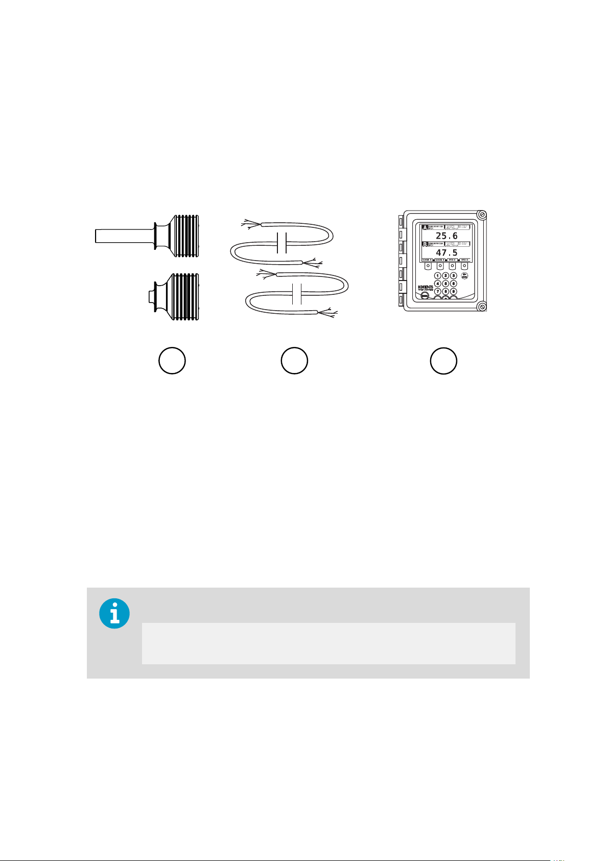
2. Product overview
The PR‑23 in‑line refractometer is an instrument for measuring liquid concentration in the
process line. The measurement is based on the refraction of light in the process medium, an
accurate and safe way of measuring liquid concentration.
Figure 1 Refractometer equipment
1 Sensors
2 Interconnecting cables
3 Indicating transmitter
The in‑line refractometer sensor (1) measures the refractive index nD and the temperature of
the process medium. This information is sent through the interconnecting cable (2) to the
indicating transmitter (3). The indicating transmitter DTR calculates the concentration of the
process liquid based on the refractive index and temperature, taking predefined process
conditions into account. The output of the DTR is a 4 to 20 mA DC output signal
proportional to process solution concentration. Process data can also be downloaded to a
computer through an Ethernet cable.
The password for PR‑23 is:
7 8 4 5 1 2
2.1 Safety
This product has been tested for safety. Note the following precautions:
13
Page 16
PR-23 Series User Guide
IM-EN-PR23-E
WARNING!
e to local and state legislation and regulations.
adher
Only licensed experts may install electrical components. They must
Precautions when removing the sensor from the process line:
Make positively sure that the process line is not under pressure. Open a vent valve to
•
the atmosphere.
• For a prism wash system, close a hand valve for the wash medium and disable the wash
valve.
• Loosen the flange or clamp cautiously, be prepared to tighten again.
• Be out of the way of any possible splash and ensure the possibility of escape.
• Use shields and protective clothing adequate for the process medium, do not rely on
avoidance of contact with the process medium.
• After removal of the sensor, it may be necessary to mount a blind cover for security
reasons.
For the Safe-Drive system safety rules, see S
Safe‑Drive generation 2.1 (page 189) and for additional precautions required by explosive
atmosphere, see PR‑23 process refractometers in potentially explosive atmosphere
(page 216).
afe sensor insertion and removal for
Wear protective eyewear.
Wear protective gloves.
It is the user’s responsibility to follow manufacturer’s safety and operating instructions. The
client’s organization has the responsibility to develop and maintain occupational safety and
create a safety culture where individuals are expected to follow safety instructions at all
times. Any negligence towards safety instructions or failure to comply with safe practices
should not be tolerated. It is the manufacturer’s responsibility to produce goods that are
safe to use when instructions are followed.
The process medium may be hot or otherwise hazardous. Use shields and protective
clothing adequate for the process medium. Do not rely on avoidance of contact with the
process medium.
14
Page 17

Chapter 2 – Product overview
2.2 Storage conditions, packaging and transportation
Soft shell packaging prevents damage to the refractometer. Transport the device in its
original packaging.
Before storing, remove any dirt and grease from the refractometer and make sure that it is
dry.
Storage conditions:
• Temperature: −40 °С…+40 °С (−40 °F… +104 °F)
• Humidity: No condensation
The product's shelf life is six months.
2.3 PR-23 refractometer models
The basic system of one or two sensors connected to an indicating transmitter (DTR) is the
same for all PR‑23 in-line refractometer models. However, there are dierent sensor models,
each model is adapted for dierent process requirements.
The models PR‑23‑AC and PR‑23‑AP meet the 3‑A Sanitary Standard requirements. With an
ATEX approved PR‑23‑…‑AX sensor or a FM approved PR‑23‑…‑FM sensor or a CSA
approved PR‑23‑…‑CS sensor or a Nepsi certified PR‑23‑…‑CX sensor a PR‑23 process
refractometer system can be used in potentially explosive atmosphere. Intrinsically safe
process refractometer PR‑23‑…‑IA/‑IF/‑CI can be used in hazardous locations in Zone 0 and
Zone 1. The Safe‑Drive system with a PR‑23‑SD sensor enables safe sensor insertion and
removal also when process line is in full operation.
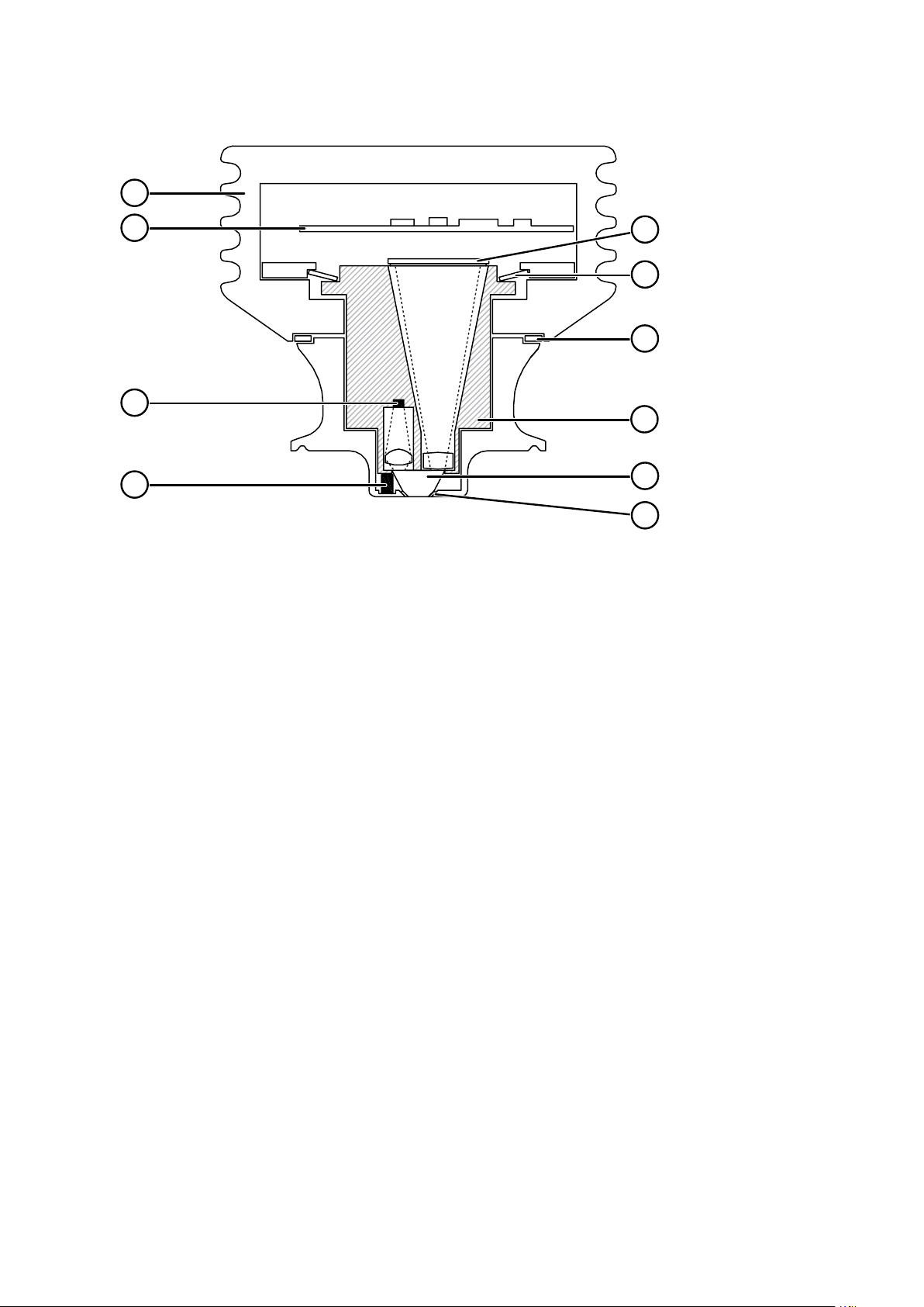
2.4
The following figure shows a cutaway picture of a refractometer sensor. The measurement
prism (6) is flush mounted to the surface of the probe tip. The prism (6) and all the other
optical components are fixed to the solid core module (7), which is springloaded (9) against
the prism gasket (5). The light source (3) is a yellow LED, and the receiver is a Charge
Couple Device (CCD) element (10). The electronics is protected against process heat by a
thermal isolator (8) and cooling fins (1). The sensor processor card (2) receives the raw data
from the CCD element (10) and the Pt‑1000 process temperature probe (4), then calculates
the refractive index nD and the process temperature T. This information is transmitted to the
indicating transmitter.
Refractometer sensor
15
Page 18
1
2
3
4
5
6
7
8
9
10
PR-23 Series User Guide
IM-EN-PR23-E
Figure 2 Sensor structure
1 Cooling fins
2 Sensor processor card
3 Light source
4 Temperature probe
5 Gasket
6 Prism
7 Core module
8 Thermal isolator
9 Disc spring
10 CCD element
16
Page 19

Chapter 3 – Mounting sensor
3. Mounting sensor
Choose the sensor mounting location with care to ensure reliable readings from the process.
Some basic rules, described in this section, apply to all sensor models. The model specific
instructions can be found in Sensor specifications (page 99).
• For the Sanitary compact refractometer PR‑23‑AC see Sanitary process refractometer
PR‑23‑AC (page 100)
• For the Probe sanitary refractometer PR‑23‑AP see Sanitary probe refractometer
PR‑23‑AP (page 113)
• For the Process probe refractometer PR‑23‑GP see Probe process refractometer
PR‑23‑GP (page 131)
• For the Teflon body refractometer PR‑23‑M and Teflon body semicon refractometer
PR‑23‑MS see Teflon body refractometer PR‑23‑M/MS (page 146)
• For the Saunders body refractometer PR‑23‑W see Saundersâ body refractometer
PR‑23‑W (page 154)
• For mounting an ATEX/FM/CSA approved sensor in explosive atmosphere, see
Installation (page 219)
• For mounting an intrinsically safe refractometer PR‑23‑…‑IA/‑CI, see Intrinsically safe
refractometers PR‑23‑…‑IA, PR‑23‑…‑IF and PR‑23‑…‑CI (page 161)
• For mounting of the Safe-Drive system with the PR‑23‑SD sensor, see Safe‑Drive
mounting (page 175)
3.1
Choosing sensor mounting location
A PR‑23 refractometer sensor can be located either indoors or outdoors in most climates.
However, when locating a sensor outdoors, make sure to provide some basic protection
against direct exposure to sunlight and rain. Take special care if the pipe wall is translucent
(for example of fiberglass), as light from outside reaching the prism through the pipe wall
may disturb the measurement.
The mounting location needs to be such that sediments or gas bubbles cannot accumulate
by the sensor. Good flow velocity is essential in keeping the prism clean.
CAUTION!
damage the in-line sensor mounted on it.
Always check that the sensor head is kept cool enough; the sensor head should not be too
hot to keep a hand on. The sensor cover should not be exposed to high temperature
radiation. In most cases, draft and natural convection provide sucient air cooling if the air
gets to flow freely around the sensor head.
If the process pipe vibrates, support the pipe. A vibrating pipe might
17
Page 20

PR-23 Series User Guide
IM-EN-PR23-E
Additional cooling is necessary when the ambient temperature is higher than 45 °C (113 °F)
or when the pr
ocess temperature is above 110 °C (230 °F) and the ambient temperature is
above 35 °C (95 °F). The air cooling is improved by blowing pressurized air against the
sensor cover. The pressurized air can be supplied by the ventilation system. If no air is
available it is also possible to install water cooling with PR‑10038 cooling cover (except for
PR‑23‑SD where sensor head needs to be kept in original size for insertion and retraction).
CAUTION!
wnwards from the sensor head.
do
Always mount the sensor so that the interconnecting cable points
18
Page 21
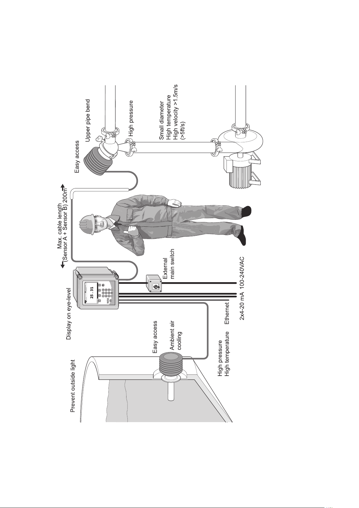
3.2 PR-23 mounting guide
Chapter 3 – Mounting sensor
19
Page 22

PR-23 Series User Guide
IM-EN-PR23-E
3.3 Pipe mounting checklist
Most in-line refractometer models are mounted in a pipe. The recommended minimum flow
velocity is 1.5 m/s (5 ft/s). The diameter and form of the pipe and the process temperature
the measurement and need to be taken into account.
aect
1. If the process pipe diameter varies, select the position with the smallest diameter (and
accordingly highest velocity). Then the prism keeps better clean.
2. If the refractometer is used in a feed-back control loop, make the time lag short. When
a dilution valve is controlled, for example, mount the refractometer close to the dilution
point. However, make sure complete mixing has occurred at mounting location.
3. If the temperature varies along the process pipe, select the position with the highest
process temperature. Then the risk of prism coating is minimized, because higher
temperature means higher solubility and also lower viscosity.
4. Often the position with the highest process pressure (= after pump + before valve) has
favorable flow
5. The sensor is accessible for service.
conditions without sedimentation or air trapping risks.
3.4 Checklist for mounting in tank, vessel or large pipe
A probe sensor PR-23-AP or PR-23-GP can be inserted with a flange or clamp into tanks and
vessels which either do not have a scraper or where the mixer does not touch the vessel
wall. A probe sensor can also be flush mounted in a cooker where the scraper touches the
wall.
1. The inserted probe sensor is mounted close to a stirrer to ensure representative sample
of the process liquid and to keep the prism clean.
2. The sensor is accessible for service.
20
Page 23
PROCESS INSTRUMENTS
P OW E R
Chapter 4 – Indicating transmitter DTR
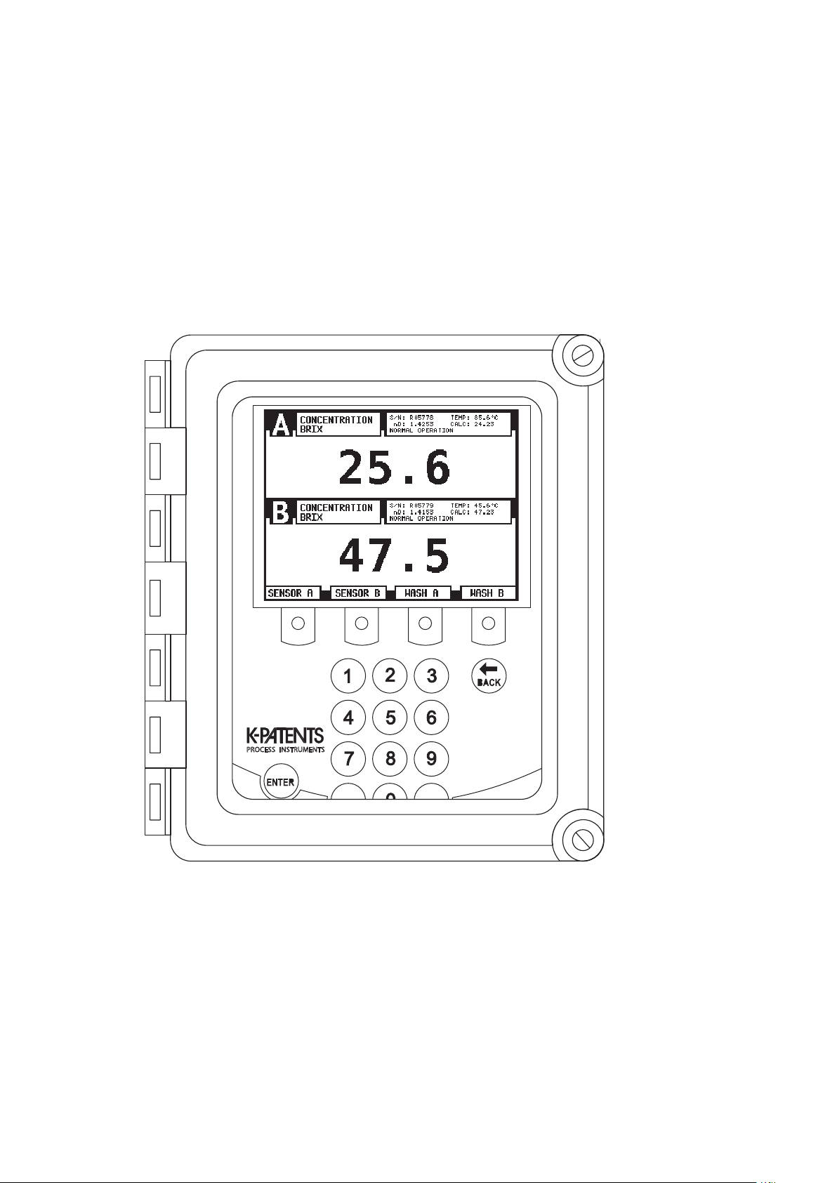
4. Indicating transmitter DTR
The indicating transmitter DTR is a specialized computer designed to process data received
from one or two sensors. The indicating transmitter enclosure contains a front panel with a
backlit LCD and a keyboard. The front panel swings open to give access for connections and
service. Both of the enclosure’s cover latches include knockout padlock provisions to
prevent unauthorized access.
Figure 3 Indicating transmitter enclosure
The sensors send the values of the refractive index nD and the process temperature T to the
DTR. The microprocessor system then linearizes the concentration reading as shown in the
following example, and performs an automatic temperature compensation.
21
Page 24

10
20
30
40
50
60
70
1.35 1.40 1.45
n
D
BRIX
PR-23 Series User Guide
IM-EN-PR23-E
Figure 4 Linearized curve
22
Page 25

Warning! The DTR does not have a built-in power
switch. The system is always powered on when
connected to a power source. It is recommended to
mount an external power switch to control the DTR’s
power supply.
Varoitus! DTR:ssä ei ole sisäänrakennettua
virtakytkintä. Järjestelmän virta on aina päällä, kun
s
e on kytketty virtalähteeseen. DTR:n virransyötön
ohjaamiseksi on suositeltavaa asentaa ulkoinen
virtakytkin.
Varning! DTR har ingen inbyggd strömbrytare.
Systemet är alltid påslaget när det är anslutet till en
strömkälla. Rekommendationen är att montera en
extern strömbrytare för att styra strömförsörjningen
till DTR:er.
Advarsel! DTR har ikke nogen indbygget afbryder.
Systemet er altid tændt, når det er tilsluttet en
strømkilde. Det anbefales at montere en ekstern
afbryder til styring af DTR'ens strømforsyning.
Hoiatus! DTR-il puudub sisseehitatud toitelüliti.
Süsteem on alati pinge all, kui on toiteallikaga
ühendatud. DTR-i toiteallika juhtimiseks on
soovitatav paigaldada väline toitelüliti.
Внимание! DTR н е имеет встроенного
переключателя питания. Если система
подключена к источнику питания, она всегда
включена. Для управления подачей питания на
DTR рекомендуется установить внешний
переключатель питания.
Įspėjimas! DTR ne turi įmontuoto maitinimo jungiklio.
Sistema visada įjungiama, kai ji yra prijungta prie
maitinimo šaltinio. DTR maitinimo šaltiniui valdyti
rekomenduojama sumontuoti išorinį maitinimo
jungiklį.
Ostrzeżenie! DTR nie zawiera wbudowanego
wyłącznika zasilania. Zasilanie systemu jest włączone
zawsze, gdy jest on podłączony do źródła zasilania.
Wskazane jest wykonanie zewnętrznego wyłącznika
zasilania do sterowania zasilaniem DTR.
Varování! DTR nemá vestavěný vypínač napájení. Po
připojení ke zdroji napájení je systém vždy zapnutý.
Pro ovládání napájení DTR se doporučuje
namontovat externí vypínač.
Figyelmeztetés! A DTR nem rendelkezik beépített
hálózati kapcsolóval. A rendszer mindig be van
kapcsolva, ha áramforráshoz csatlakozik. A DTR
tápellátásának vezérléséhez ajánlott egy külső
tápkapcsolót felszerelni.
Warnung! Der DTR ist nicht mit einem eingebauten
Netzschalter ausgestattet. Das System ist immer
eingeschaltet, wenn es an eine Stromquelle
angeschlossen ist. Es wird empfohlen, einen externen
Netzschalter zu installieren, um die Stromversorgung
des DTR zu steuern.
Waarschuwing! De DTR heeft geen ingebouwde
voedingsschakelaar. Het systeem is altijd
ingeschakeld wanneer het is aangesloten op een
voedingsbron. Het wordt aanbevolen om
een
externe voedingsschakelaar
te monteren om de
voeding van de DTR te regelen.
Avertissement ! Le DTR n’est pas équipé d’un
interrupteur d'alimentation intégré. Le système est
toujours sous tension lorsqu'il est connecté à une
source d'alimentation. Il est recommandé de monter
un interrupteur d'alimentation externe pour
contrôler l'alimentation du DTR.
¡Advertencia! El DTR no tiene un interruptor de
encendido integrado. El sistema siempre está
encendido cuando está conectado a una fuente de
alimentación. Se recomienda montar un interruptor
de encendido externo para controlar la fuente de
alimentación del DTR.
Avvertimento! Il DTR non dispone di un interruttore
di alimentazione integrato. Il sistema è sempre
acceso quando è collegato a una fonte di
alimentazione. Si consiglia di montare un interruttore
di alimentazione esterno per controllare
l'aliment
azione del DTR.
Warning
Chapter 4 – Indicating transmitter DTR
4.1 Mounting indicating transmitter
23
Page 26
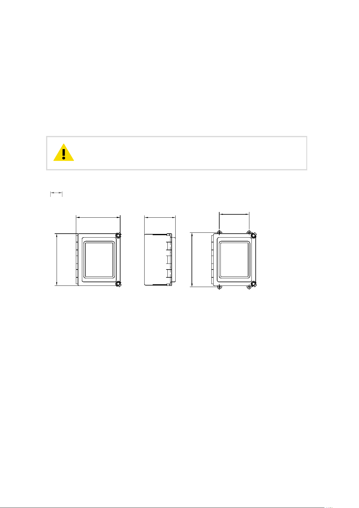
mm
[in]
267 [10.5]
226 [8.9] 159 [6.25]
278 [10.94]
152 [6.0]
PR-23 Series User Guide
IM-EN-PR23-E
Mount the indicating transmitter indoors, preferably in an easily accessible, well-lit and dry
ea. Avoid vibration. Take interconnecting cable length into consideration when choosing
ar
the mounting location.
The enclosure is mounted vertically on an upright surface (wall) using four mounting feet,
see the following figure. The LCD is best viewed when approximately at the eye level of the
user.
In sanitary installations, the recommendation is to use a DTR with stainless steel enclosure. If
standard polycarbonate enclosure is used, install it as remotely as practical from product
areas or connections.
CAUTION!
class of the enclosure and damage the electronics.
Figure 5 Indicating transmitter dimensions and mounting feet measures
Do not drill mounting holes in the enclosure as that aec
t the protection
4.2 Electrical connections
4.2.1 Interconnecting cable
The cable contains a pair of twisted signal wires and a cable shield, see
Standard delivery is 10 m (33 ft) of cable. The maximum length of an interconnecting cable
is 200 m (660 ft). The signal wires are interchangeable (non-polarized). The cable shield is
connected to the protective earth at the indicating transmitter.
The junction box enables the use of customer’s own cable as long as it meets IEC 61158-2
type A standard requirements, see Interconnecting cable specifications (page 226).
More information
‣
Connecting sensor (page 25)
24
Figure 9 (page 31).
Page 27

4.2.2 Connecting sensor
Chapter 4 – Indicating transmitter DTR
CAUTION!
energized. Switch o the power from indicating transmitter DTR external power switch
before disconnecting the sensor cable from the sensor. After connecting the sensor
cable back to the sensor, you can switch power back on.
Do not connect or disconnect the sensor connector when the circuits are
1. Remove the four screws holding the sensor nameplate as shown in the following figure.
The terminal strip is under the nameplate.
2. Connect the signal wires to terminal (1) and (2), and the cable shield to terminal (3).
3. Tighten up the cable gland.
25
Page 28

1
2
3
PR-23 Series User Guide
4. Screw the nameplate back on.
IM-EN-PR23-E
Figure 6 Sensor electrical connections
More information
‣
Interconnecting cable (page 24)
26
Page 29

Warning! Check that the power is off before opening
the front panel. If the green power indicator light is
on, there is still power in the system. To completely
turn the power off, use the external power switch.
Varoitus! Tarkista, että virta on katkaistu, ennen kuin
avaat etupaneelin. Jos vihreä virran merkkivalo
palaa, järjestelmässä on edelleen virtaa. Katkaise
virta kokonaan ulkoisella virtakytkimellä.
Varning! Kontrollera att strömmen är avstängd innan
du öppnar frontpanelen. Om den gröna
indikatorlampan lyser är det fortfarande ström i
systemet. Använd den externa strömbrytaren för att
stänga av strömmen helt.
Advarsel! Kontroller, at strømmen er slukket, før
frontpanelet åbnes. Hvis den grønne
strømindikatorlampe er tændt, er der stadig strøm i
systemet. Brug den eksterne afbryder for at slukke
helt for strømmen.
Hoiatus! Enne esipaneeli avamist kontrollige, et
süsteem poleks pinge all. Kui roheline toitemärgutuli
põleb, on süsteemis endiselt pinge all. Toite
täielikuks väljalülitamiseks kasutage välist toitelülitit.
Внимание! Перед открытием передней панели
убедитесь, что питание отключено. Если горит
зеленый индикатор питания, система находится
под напряжением. Чтобы полностью отключить
питание, используйте внешний переключатель
питания.
Įspėjimas! Prieš atidarydami priekinį skydelį,
patikrinkite, ar maitinimas išjungtas. Jei šviečia žalia
maitinimo indikatoriaus lemputė, sistemoje vis dar
veikia maitinimas. Norėdami visiškai išjungti
maitinimą, naudokite išorinį maitinimo jungiklį.
Ostrzeżenie! Przed otwarciem panelu przedniego
sprawdzić, czy zasilanie jest wyłączone. Dopóki
świeci się zielona kontrolka zasilania, system
znajduje się pod napięciem zasilania. W celu
całkowitego wyłączenia zasilania należy użyć
zewnętrznego wyłącznika zasilania.
Varování! Před otevřením předního panelu
zkontrolujte, zda je napájení vypnuto. Pokud svítí
zelená kontrolka napájení, je v systému stále
přítomno napájení. Chcete-li napájení zcela vypnout,
použijte externí vypínač.
Figyelmeztetés! Az előlap kinyitása előtt ellenőrizze,
hogy a készülék ki van-e kapcsolva. Ha a zöld
tápellátás jelzőfény világít, akkor a rendszer még
áram alatt van. A készülék teljes kikapcsolásához
használja a külső tápkapcsolót.
Warnung! Prüfen Sie, ob das Gerät ausgeschaltet ist,
bevor Sie die Frontblende öffnen. Wenn die grüne
Betriebsanzeige leuchtet, liegt noch Spannung an.
Verwenden Sie den externen Netzschalter, um das
Gerät vollständig auszuschalten.
Waarschuwing! Controleer of de stroom is
uitgeschakeld voordat u het voorpaneel opent. Als
het groene stroomindicatielampje brandt, staat er
nog stroom op het systeem. Gebruik de externe
voedingsschakelaar om de stroom volledig uit te
schakelen.
Avertissement! Vérifiez que l'alimentation est
coupée avant d'ouvrir le panneau avant. Si le voyant
d'alimentation vert est allumé, le système est
toujours sous tension. Pour mettre l'appareil
complètement hors tension, utilisez l'interrupteur
d'alimentation externe.
¡Advertencia! Verifique que la alimentación está
desconectada antes de abrir el panel frontal. Si la luz
indicadora de encendido de color verde está
encendida, aún hay energía en el sistema. Para
apagar completamente la alimentación, use el
interruptor de encendido externo.
Avvertimento! Verificare che l'alimentazione sia
spenta prima di aprire il pannello anteriore. Se la spia
di alimentazione verde è accesa, il sistema è ancora
alimentato. Per spegnere completamente
l'alimentazione, utilizzare l'interruttore di
alimentazione esterno.
Warning
Chapter 4 – Indicating transmitter DTR
4.2.3 Connecting indicating transmitter
27
Page 30

Warning! Hazardous voltage, contact may cause
electric shock or burn. Beware of the live wires in the
lower right-hand corner of the H1 interface card.
Varoitus! Vaarallinen jännite – kosketus voi aiheuttaa
sähköiskun tai palovammoja. Varo jännitteisiä johtoja
H1-liitäntäkortin oikeassa alakulmassa.
Varning! Farlig spänning. Kontakt kan leda till elstöt
eller brännskador. Var försiktig med de strömförande
kablarna i det nedre högra hörnet på H1gränssnittskortet.
Advarsel! Farlig spænding, kontakt kan forårsage
elektrisk stød eller forbrænding. Vær opmærksom på
de strømførende ledninger i nederste højre hjørne af
H1-interfacekortet.
Hoiatus! Ohtlik pinge, kokkupuutel võite saada
elektrilöögi või põletuse. Ettevaatust voolu all
olevate juhtmetega H1-liidesekaardi all paremas
nurgas.
Внимание! Опасное напряжение, при контакте
можно получить удар электрическим током или
ожог. Остерегайтесь проводов под напряжением
в правом нижнем углу интерфейсной платы H1.
Įspėjimas! Pavojinga įtampa, kontaktas gali sukelti
elektros smūgį arba užsidegimą. Saugokitės įtampos
laidų, esančių apatiniame dešiniajame H1 sąsajos
kortelės kampe.
Ostrzeżenie! Niebezpieczne napięcie, dotknięcie
grozi porażeniem prądem lub oparzeniem. Uważać
na przewody pod napięciem w prawym dolnym rogu
karty interfejsu H1.
Varování! Nebezpečné napětí, kontakt může
způsobit úraz elektrickým proudem nebo popálení.
Dejte si pozor na vodiče pod napětím v pravém
dolním rohu karty rozhraní H1.
Figyelmeztetés! Veszélyes feszültség, érintése
áramütést vagy égési sérülést okozhat. Óvakodjon a
feszültség alatt lévő vezetékektől a H1
interfészkártya jobb alsó sarkában.
Warnung! Gefährliche Spannung, Kontakt kann
Stromschlag oder Verbrennungen verursachen.
Halten Sie sich von den stromführenden Kabeln
unten rechts an der H1 Schnittstellenkarte fern.
Waarschuwing! Gevaarlijke spanning, contact kan
elektrische schokken of brandwonden veroorzaken.
Pas op voor de spanningvoerende draden in de
rechterbenedenhoek van de H1-interfacekaart.
Avertissement! Tension dangereuse, un contact peut
provoquer un choc électrique ou des brûlures.
Prenez garde aux fils sous tension dans le coin
inférieur droit de la carte d'interface H1.
¡Advertencia! El contacto con voltaje peligroso
puede causar descargas eléctricas o quemaduras.
Tenga cuidado con los cables activos en la esquina
inferior derecha de la tarjeta de interfaz H1.
Avvertimento! Tensione pericolosa, il contatto può
causare scosse elettriche o ustioni. Attenzione ai fili
sotto tensione nell'angolo inferiore destro della
scheda di interfaccia H1.
Warning
PR-23 Series User Guide
IM-EN-PR23-E
All the electrical terminals of the indicating transmitter are behind the front panel. To access
them,
first open the enclosure cover. Then loosen the front panel screw in the figure below,
and swing open the front panel. All terminals are now accessible.
28
Page 31

1
2
Chapter 4 – Indicating transmitter DTR
Figure 7 Opening indicating transmitter front panel
1 Power indicator light
2 Front panel screw
Make sure that you mount an external power switch for the divert control unit that is close to
the unit and easily reachable. Make sure that you mark it as a disconnecting device. The
following figure shows the recommended external power switch, spare part nr PR‑10900.
The ratings of the switch are 10 A/250 V.
29
Page 32

PR-23 Series User Guide
IM-EN-PR23-E
Figure 8 External power switch
The following
30
figure shows the motherboard of the indicating transmitter for AC power.
Page 33

6
Chapter 4 – Indicating transmitter DTR
Figure 9 Motherboard (AC power)
The following figure shows the motherboard of the indicating transmitter for 24 VDC power.
31
Page 34

+
-
POWER
6
PR-23 Series User Guide
IM-EN-PR23-E
Figure 10 Motherboard (24 VDC)
he following table describes the terminals on the H1 interface card PR‑10701 and on the
T
transmitter motherboard PR‑10600.
Terminal Usage
On H1
A 1 2 3 Connection for Sensor A, signal wires (1, 2), cable shield (3).
B 1 2 3 Connection for Sensor B, signal wires (1, 2), cable shield (3).
On motherboard
11 12 4 … 20 mA output 1, positive (11), negative (12), max. load 1000 Ω,
galv
anically isolated.
13 14 4 … 20 mA output 2, positive (13), negative (14), max. load 1000 Ω,
galv
anically isolated.
21 22 Relay 1, one contact output, max. 250 VAC, max. 3 A.
23 24 Relay 2, one contact output, max. 250 VAC, max. 3 A.
31 32 33 Power, L (31), N (32), protective earth (33), 100 … 240 VAC, 50 … 60 Hz,
fuse with v
power switch is mandatory.
oltage 250 VAC, max. size 10 A and speed slow. An external
32
Page 35

Chapter 4 – Indicating transmitter DTR
Terminal Usage
41 42 24 V terminal for DTR internal use only.
Connecting terminal to external 24 V supply voids
the warranty. Connecting external devices to 24 V
terminal voids the warranty.
51 52 53 54 55 Switch inputs: switch 1 (51), switch 2 (52), switch 3 (53), switch 4 (54)
and common 3 V for all inputs (55). The switch terminals are galvanically
isolated.
4.2.4 Power terminals for AC power
The primary AC power is connected to a separate terminal strip 31/32/33 marked POWER in
the lower right-hand corner of the motherboard. The three terminals are marked 31/L, 32/N
and 33/ (protective earth). The power terminal 33/ is directly connected to the exposed
metal parts of the indicating transmitter DTR. Wiring to the terminals must be of min.
1.5 mm2. The fuse voltage should be 250 V, max. size 10 A and fuse speed slow. Ensure that
the protective fuse in the building system complies with local requirements.
4.2.5
Power terminals for 24 VDC power
The DC power is connected to a terminal stripe marked POWER in the lower right-hand
corner of the motherboard. The three terminals are marked +, − and (protective earth). The
power terminal is directly connected to the exposed metal parts of the Indicating
transmitter DTR.
The 24 VDC power to this terminal stripe must be supplied from a secondary circuit which is
double or reinforced insulated from the mains supply within the limits for a limited-energy
circuit (maximum 200 VA/U) according to the IEC 61010-1.
33
Page 36

Warning! Connect only AC or DC power to relays.
You can connect AC power to both relays or DC
power to both relays, but never connect AC in one
and DC in the other relay.
Varoitus! Kytke releisiin vain vaihtovirta tai tasavirta.
Voit kytkeä vaihtovirran molempiin releisiin tai
tasavirran molempiin releisiin, mutta älä koskaan
kytke yhteen releeseen vaihtovirtaa ja toiseen
releeseen tasavirtaa.
Varning! Anslut endast en AC- eller DC-strömkälla
till reläer. Du kan ansluta en AC-strömkälla till båda
reläerna eller en DC-strömkälla till båda reläerna,
men aldrig ansluta en AC-strömkälla till det ena
reläet och en DC-strömkälla till det andra.
Advarsel! Tilslut kun vekselstrøm eller jævnstrøm til
relæerne. Du kan slutte vekselstrøm til begge relæer
eller jævnstrøm til begge relæer, men tilslut aldrig
vekselstrøm til det ene og jævnstrøm til det andet
relæ.
Hoiatus! Ühendage releed ainult vahelduvvoolu- või
alalisvooluvõrku. Võite mõlemad releed ühendada
kas vahelduvvooluvõrku või alalisvooluvõrku, ent
mitte kunagi ühte releed vahelduvvooluvõrku ja teist
alalisvooluvõrku.
Внимание! Подключайте к реле только питание
переменным или постоянным током. К обоим реле
можно подключить питание переменным или
постоянным током, но никогда не подключайте к
одному реле питание переменным током, а к
другому ----- питание постоянным током.
Įspėjimas! Prijunkite tik AC arba nuolatinę srovę
relėms. Galite prijungti kintamąją srovę prie abiejų
relių arba nuolatinę srovę prie abiejų relių, bet
niekada nejunkite kintamosios srovės vienoje ir
nuolatinės srovės kitoje.
Ostrzeżenie! Do przekaźników podłączać tylko AC
lub DC. Do obu przekaźników może być podłączone
zasilanie AC lub zasilanie DC, ale nie wolno
podłączać zasilania AC do jednego, a zasilania DC do
drugiego przekaźnika.
Varování! K relé připojte pouze střídavé nebo
stejnosměrné napájení. Můžete připojit střídavé
napájení k oběma relé nebo stejnosměrné napájení k
oběma relé, ale nikdy nepřipojujte k jednomu relé
střídavé a k druhému stejnosměrné napájení.
Figyelmeztetés! Csak AC vagy csak DC tápellátást
csatlakoztasson a relékhez. Csatlakoztathat AC
tápellátást mindkét reléhez, vagy DC tápellátást
mindkét reléhez, de soha ne csatlakoztasson az
egyikhez AC, a másikhoz pedig DC tápellátást.
Warnung! Nur Wechselstrom oder Gleichstrom an
die Relais anschließen. Sie können Wechselstrom an
beide Relais oder Gleichstrom an beide Relais
anschließen, dürfen aber keinesfalls Wechselstrom
an ein und Gleichstrom an das andere Relais
anschließen.
Waarschuwing! Sluit alleen AC- of DC-voeding aan
op relais. U kunt AC-voeding aansluiten op beide
relais of DC-voeding op beide relais, maar sluit nooit
AC-voeding aan op het ene en DC-voeding aan op
het andere relais.
Avertissement! Connectez uniquement une
alimentation CA ou CC aux relais. Vous pouvez
connecter une alimentation CA aux deux relais ou
une alimentation CC aux deux relais, mais ne
connectez jamais une alimentation CA à un relais et
une alimentation CC à l'autre relais.
¡Advertencia! Conecte solo la alimentación de CA o
de CC a los relés. Puede conectar la alimentación de
CA a ambos relés o la alimentación de CC a ambos
relés, pero nunca podrá conectar una alimentación
de CA en un relé y una alimentación de CC en el otro
relé.
Avvertimento! Collegare ai relè solamente
l'alimentazione CA o CC. È possibile collegare
l'alimentazione CA o CC a entrambi i relè, ma non
collegare mai l'alimentazione CA in un relè e
l'alimentazione CC nell'altro relè.
Warning
PR-23 Series User Guide
4.2.6 Relay connections
IM-EN-PR23-E
34
Page 37

Warning! Items DD-23-M-GP-DC and DD-23-U-GPDC are PELV devices. See type label for supply
voltage specifications. Connect the protective
grounding to the same grounding potential that is
used by the external power supply.
Varoitus! Tuotteet DD-23-M-GP-DC ja DD-23-U-GPDC ovat PELV-laitteita. Katso syöttöjännitteen
tekniset tiedot tyyppikilvestä. Kytke suojamaadoitus
samaan maadoituspotentiaaliin kuin mitä ulkoinen
virtalähde käyttää.
Varning! Objekten DD-23-M-GP-DC och
DD-23-U-GP-DC är PELV-enheter. Se typskylt för
specifikationer för matningsspänning. Anslut
skyddsjordning till samma jordningspotential som
används för den externa strömförsörjningen.
Advarsel! Komponent DD-23-M-GP-DC og
DD-23-U-GP-DC er PELV-enheder. På typemærkatet
kan du se specifikationerne for forsyningsspænding.
Forbind den beskyttende jordforbindelse til den
samme jording, som den eksterne strømforsyning
bruger.
Hoiatus! Seadmed DD-23-M-GP-DC ja DD-23-U-GPDC on PELV-kaitseväikepingega töötavad seadmed.
Toitepinge spetsifikatsioone vt tüübisildilt. Ühendage
kaitsemaandus sama maanduspotentsiaaliga, mida
kasutab väline toiteallikas.
Внимание! Элементы DD-23-M-GP-DC и
DD-23-U-GP-DC ----- это устройства защитного
сверхнизкого напряжения. Технические
характеристики напряжения питания см. в
табличке с паспортными данными. Подключите
защитное заземление к тому же потенциалу
заземления, который используется внешним
источником питания.
Įspėjimas! Prekės DD - 23 - M - GP - DC ir
DD - 23 - U - GP - DC yra PELV prietaisai. Maitinimo
įtampos specifikacijas žr. tipo etiketėje. Prijunkite
apsauginį įžeminimą prie to paties įžeminimo
potencialo, kurį naudoja išorinis maitinimo šaltinis.
Ostrzeżenie! Pozycje DD-23-M-GP-DC i
DD-23-U-GP-DC są urządzeniami PELV. Wartości
znamionowe napięcia zasilania podane są na
tabliczce znamionowej. Uziemienie ochronne musi
być podłączone do tego samego potencjału
uziomowego, które jest wykorzystywane przez
zewnętrzne zasilanie.
Varování! Položky DD-23-M-GP-DC a
DD-23-U-GP-DC jsou zařízení PELV. Specifikace
napájecího napětí najdete na typovém štítku.
Připojte ochranné uzemnění ke stejnému zemnícímu
potenciálu, jaký využívá externí napájecí zdroj.
Figyelmeztetés! A DD-23-M-GP-DC és a
DD-23-U-GP-DC elemek PELV készülékek. A
tápfeszültség specifikációit lásd a típuscímkén.
Csatlakoztassa a védőföldelést ugyanahhoz a
földelési potenciálhoz, mint amelyet a külső
tápegység használ.
Warnung! DD-23-M-GP-DC und DD-23-U-GP-DC
sind PELV-Komponenten. Die Spannungsangaben
sind dem Typenschild zu entnehmen. Schließen Sie
die Schutzerde an das von der externen
Stromversorgung verwendete Erdpotential an.
Waarschuwing! Items DD-23-M-GP-DC en
DD-23-U-GP-DC zijn PELV-apparaten. Zie
typeplaatje voor specificaties van de
voedingsspanning. Sluit de beschermende aarding
aan op hetzelfde aardingspotentiaal dat wordt
gebruikt door de externe voeding.
Avertissement! Items DD-23-M-GP-DC et
DD-23-U-GP-DC sont des appareils TBTP. Voir
l'étiquette de type pour les spécifications de tension
d'alimentation. Connectez la mise à la terre de
protection au même potentiel de mise à la terre
utilisé par l'alimentation externe.
¡Advertencia! Los elementos DD-23-M-GP-CC y
DD-23-U-GP-CC son dispositivos PELV. Consulte la
etiqueta de tipo para conocer las especificaciones
del voltaje de suministro. Conecte la puesta a tierra
de protección al mismo potencial de puesta a tierra
que usa la fuente de alimentación externa.
Avvertimento! Gli articoli DD-23-M-GP-CC e
DD-23-U-GP-CC sono dispositivi PELV. Vedere la
targhetta del modello per le specifiche della tensione
di alimentazione. Collegare la messa a terra di
protezione allo stesso potenziale di messa a terra
utilizzato dall'alimentazione esterna.
Warning
Chapter 4 – Indicating transmitter DTR
35
Page 38

Reset
button
PR-23 Series User Guide
IM-EN-PR23-E
4.2.7 Reset button
You can reset and restart both the indicating transmitter DTR and the sensor by pushing the
eset button. You can access the button through the cable hole in the front panel shield as
r
shown in the following figure. To reach the reset button, use a thin stick or similar utensil,
preferably of non-conducting material. After pushing the reset button, the display blacks out
for a few seconds. The instrument returns to full operation within 30 s.
Figure 11 Location of reset button
36
Page 39

Chapter 5 – Prism wash systems
5. Prism wash systems
5.1 Prism coating
Deposit build-up on the prism surface disturbs the measurement. Look out for an
abnormally high concentration reading or an upward concentration (CONC) drift.
In most applications the prism keeps clean due to the self-cleaning eect. If coating occurs,
check the following:
• Sucient flow velocity, see Pipe mounting checklist (page 20).
• A temperature dierence between process fluid and sensor probe can cause coating.
This can happen with small flows if the thermal insulation is inadequate. In some cases
it also helps to insulate the clamp connector.
In case of a coating problem, the preferred solution is to try to increase the flow velocity, for
example, by installing a pipe portion with smaller diameter.
Consider installing a wash nozzle, if increasing the velocity or using a flow booster does not
provide a solution. See Prism wash (page 37).
5.2 Prism wash
Three alternative media can be used for prism wash:
• Steam
• Water
• High pressure water
The built-in relays of the indicating transmitter can be configured to control the prism wash
cycle, see Configuring relays (page 66).
CAUTION!
water. Shut-o valve and check valve must meet 3‑A sanitary standards.
Culinary Steam: Steam produced using a system meeting criteria in the 3‑A Accepted
Practices for a Method of Producing Steam of a Culinary Quality, Number 609.
Safe Water: Water from a supply properly located, protected, and operated, and of safe,
sanitary quality. The water must meet the standards prescribed in the National Primary
Drinking Water Regulation of the Environmental Protection Agency (EPA) as referenced in
The Code of Federal Regulations (CFR), Title 40, Parts 141, 142, and 143.
In food industry applications, wash media must be culinary steam or safe
Recommended wash pressures and times
5.2.1
The following tables show the recommended wash pressures and times.
37
Page 40

PR-23 Series User Guide
IM-EN-PR23-E
Table 3 Wash medium parameters for integral wash nozzles in PR‑23‑AP
Minimum
ve process
abo
pressure
Steam (SN) 2 bar (30 psi) 4 bar (60 psi) 3 s 20 … 30 s 20 … 30 min
Water (WN) 2 bar (30 psi) 4 bar (60 psi) 3 s 20 … 30 s 20 … 30 min
High pressure
w
ater (WP)
15 bar (220 psi) 40 bar (600 psi) 10 s 20 … 30 s 10 … 20 min
Table 4 Wash medium parameters for flo
Minimum
ve process
abo
pressure
Steam (SN) 3 bar (45 psi) 6 bar (90 psi) 3 … 5 s 20 … 30 s 20 … 30 min
Water (WN) 3 bar (45 psi) 6 bar (90 psi) 10 … 15 s 20 … 30 s 10 … 20 min
High pressure
w
ater (WP)
25 bar (350 psi) 35 bar (500 psi) 10 … 15 s 20 … 30 s 10 … 20 min
Maximum
above process
pressure
w cell wash nozzle AFC
Maximum
above process
pressure
Wash time Recovery Interval
Wash time Recovery Interval
/GP
Table 5 Wash medium parameters for Safe‑Driv
CONC %
alue
v
Steam (SN) 10 … 30 % 2 bar (30 psi) 4 bar (60 psi) 2 … 3 s 20 s 120 … 360 mi
30 … 60 % 3 bar (45 psi) 6 bar (90 psi) 3 s 20 s 20 … 60 min
60 … 90 % 4 bar (60 psi) 8 bar
High pressure water (WP) 25 bar
CAUTION!
ocess media can burn to the prism surface if steamed for longer time. In case of
pr
Minimum
above
process
pressure
(3
50 psi)
In steam wash, do not exceed the recommended wash times, because some
e isolation valve nozzle SDI
Maximum
above
process
pressure
(120 psi)
30 bar
(435 psi)
Wash time Recovery Interval
3 … 5 s 20 s 15 … 25 min
10 … 15 s 20 s 5 … 20 min
n
coating, shorten the wash interval.
For the Automatic wash cut parameter, see Setting prism wash parameters (page 82).
38
In water wash, water temperature should be above the process temperature.
Page 41

V A I S A L A
VAI S
A L
A
V A I S A L A
V A I S A L A
V A I S A L A
V A I S A L A
V
A ISA L A
V A I
V A I
V A I
Chapter 5 – Prism wash systems
The check valve pressure drop is 0.7 bar (10 psi).
5.2.2 Prism wash systems
The following figures describe the prism wash systems for steam and for sanitary systems.
Figure 17 (page 44) describes the prism wash system for high pressure water.
Figure 12 Prism wash system for steam (non-sanitary)
39
Page 42

VAISA L A
V A ISA L A
V A I S A L A
V A I S A L A
V A I S A L A
V
A I
PR-23 Series User Guide
IM-EN-PR23-E
Figure 13 Sanitary prism wash system for steam
In case of excessive pressure in steam systems: If the steam pressure exceeds the maximum
pressure dierential,
install a pressure reducing valve PR‑3341‑J to reduce the steam
pressure to optimal design.
40
Page 43

Chapter 5 – Prism wash systems
Figure 14 Pressure reducing valve PR‑3341‑J
Note the orientation of the strainer.
41
Page 44

Horizontal
Vertical
PR-23 Series User Guide
IM-EN-PR23-E
Figure 15 Install strainer horizontally
42
Page 45

Chapter 5 – Prism wash systems
Figure 16 Wiring for a prism wash system for steam
43
Page 46

PR-23 Series User Guide
IM-EN-PR23-E
WARNING!
pipe sec
In high pressure wash systems, pressure increase can occur in a closed
tion when the high pressure pump is operated. It is recommended to mount a
pressure relief valve in the pipe section. Relief pressure must be according to pipe
pressure rating.
Figure 17 Prism wash system for high pressure water
44
Page 47

Chapter 5 – Prism wash systems
Figure 18 Wiring for prism wash system for high pressure water
45
Page 48

A
Flow cell -H10 or -H15
A B part nr
steam
64.75
4.0
PR-3365
water
75
2.5
PR-3369
pressurized water
75
1.5
PR-3368
Flow cell -H20 or -H25
A B part nr
steam
72.15
4.0
PR-3375
water
97
2.5
PR-3379
pressurized water
97
1.5
PR-3378
Flow cell -H30
A B part nr
steam 103 4.0 PR-3393
water 113 2.5 PR-3394
pressurized water 113 1.5 PR-3395
Flow cell -H40
A B part nr
steam 133 4.0 PR-3390
water 143 2.5 PR-3391
pressurized water 143 1.5 PR-3392
PR-23 Series User Guide
5.2.3 Prism wash nozzles
IM-EN-PR23-E
When selecting a wash nozzle for a c
ompact refractometer, take into account both the
wash medium and the flow cell model: flow cells with larger pipe diameters need longer
wash nozzles. The figure below shows a wash nozzle for a flow cell and gives the
measurements and part numbers for each nozzle type.
Figure 19 Wash nozzles for flow cell AFC‑HSS‑XXX‑XX‑NC
The following
wash nozzle).
46
figure shows how the nozzle is mounted in a flow cell (‑NC with stud for a
Page 49

Figure 20 Process connection of wash nozzle in flow cell
Chapter 5 – Prism wash systems
For more information on flow cells, see PR‑23‑AC mounting specifics (page 107).
The following table lists wash nozzles according to wash medium and refractometer model
for probe refractometers.
Table 6 Prism wash nozzle selection
PR23‑AP PR‑23‑GP
Steam nozzle PR‑9321 PR‑9324
Water nozzle PR‑9320 PR‑9323
Pressurized water nozzle PR‑9322 PR‑9325
Figure 21 (page 48) shows the mounting of the wash nozzle for sanitary probe
refractometer PR-23-AP. Figure 22 (page 49) shows the mounting of the wash nozzle for
process refractometer PR-23-GP.
47
Page 50

PR-23 Series User Guide
IM-EN-PR23-E
Figure 21 Mounting of wash nozzle for sanitary probe refractometer PR‑23‑
48
AP
Page 51

VAISALA
VAISALA
VAISALA
VAISALA
VAISALA
mm
[in]
Chapter 5 – Prism wash systems
Figure 22 Mounting of wash nozzle for process refractometer PR‑23‑GP
49
Page 52

Main display for two sensors Main display for single
sensor, concentration only
Main display for single sensor,
concentration and temperature
Main display for single sensor,
concentration and bar graph
PR-23 Series User Guide
6. Startup and use
6.1 Startup
6.1.1 Initial check
IM-EN-PR23-E
Figure 23 Main display alternatives
1. Check the wiring, see Electrical connections (page 24).
2. Connect the power. The power indicator light and the screen light up within a few
seconds.
3. The Main display comes up, as shown in Figure 23 (page 50)
4
. In case the display shows a row of dashes, there is no corresponding sensor (for
example in the figure above, upper left, there is no sensor A, only sensor B is
connected). The diagnostic message is NO SENSOR for that sensor.
5. Check the serial number of the sensor at the upper right corner in the display.
50
.
Page 53

Chapter 6 – Startup and use
6. For a connected sensor, the diagnostic message at start-up is Normal operation or NO
SAMPLE if the process pipe is empty. If another diagnostic message is shown instead,
see Diagnostic message priorities (page 97).
7. The TEMP value shows the current process temperature.
8. To check the value and the correct setup of the two mA output signals, select
DESCRIPTION in the Main menu and then mA OUTPUTS in the Description menu, see
Viewing system information (page 55).
9. If internal relays or switch inputs are used, you can check their settings through the
Description menu, see Viewing system information (page 55).
6.1.2 Calibration check
Wait until normal process conditions occur. The concentration reading is precalibrated at
delivery and a copy of the Sensor calibration certificate is inside the Indicating transmitter. If
the diagnostic message is Normal operation but the concentration reading does not agree
with the laboratory results, see Calibrating concentration measurement (page 72).
6.1.3
Testing prism wash
1. Check that the steam or water washing parts are connected.
2. In the Main display, press MENU. Then press 3 (to give the command SENSOR STATUS).
In this sensor status display by pressing the soft key WASH. If soft key WASH does not
appear, no internal relay is configured for this purpose.
3. Check the nD reading, for a successful wash it must drop below 1.34 during steam wash
and drop to approximately 1.33 during water wash.
CAUTION!
of the refractometer sensor.
More information
‣
Prism wash systems (page 39)
6.2
Using indicating transmitter
Before testing prism wash, check that there is liquid in the pipe in front
The indicating transmitter DTR receives the refractive index value nD and the process
temperature from the sensor. Starting from these values, it calculates the concentration of
the process media for display and further transmission. The DTR can also be programmed to
give alarm for high or low concentration. If the refractometer has a prism wash system, the
DTR can control the wash with its built-in timer.
More information
‣
Configuration and calibration (page 59)
51
Page 54

INSTRUMENTS
P OW E R
PR-23 Series User Guide
IM-EN-PR23-E
6.2.1 Keyboard functions
Number keys: The 10 number keys, minus sign, and decimal point are used to enter
numerical par
ENTER key: The ENTER key is used to implement the selected (highlighted) menu command
or to accept an entered value.
BACK key: The commands are arranged into a decision tree, the BACK key is used to move
one step backward to the preceding display. It is also used to erase or cancel a numerical
input.
Soft keys: The meaning of the soft key is shown on the display immediately above the key.
The figure below gives an example the soft key functions, from left to right:
1. SENSOR A: Switch to corresponding menu for Sensor A.
2. Arrow down: Move one step down in the menu.
3. Arrow up: Move one step up in the menu.
4. SELECT: Select the highlighted command (equivalent to pressing ENTER).
ameters. They are also used for menu selections.
Figure 24 DTR keyboard and Main menu for sensor B
52
Page 55

Chapter 6 – Startup and use
Press the key under the display. The display is not touch sensitive.
6.2.2 Display setup
Selecting MENU / MENU A / MENU B or SENSOR A or SENSOR B (depending on your Main
display format) in the Main display gives the menu display. Choose 4 DISPLAY SETUP to
change the Main display format and bar graph settings, to adjust backlight or contrast and
to invert the display. In DTR program version 2.0 or newer you can also switch between the
existing display languages.
Figure 25 Display setup menu
Main display format: As shown in Figure 23 (page 50), there are four dierent Main display
formats: the dual sensor format shows information on both sensors while the three dierent
single sensor formats show selected information on one sensor at a time. Choose 1 MAIN
DISPLAY FORMAT in the Display setup menu to change the Main display. The current format
is shown on the display format selection display, as shown in the figure below.
53
Page 56

PR-23 Series User Guide
IM-EN-PR23-E
Figure 26 Main display format selection
An automatic 60 s (in v
the Main display is reached.
Display appearance: T
he 2 DISPLAY BACKLIGHT & CONTRAST can be selected from the
erification 5 min) timeout makes backsteps from any display until
Display setup menu, see Figure 25 (page 53). The values can be changed by using the arrow
soft keys or alternatively a one digit input, for example 8 designates 80 % when adjusting
contrast.
The 3 DISPLAY INVERSION contains two choices. The default setting of the display is 1
POSITIVE DISPLAY, which is a yellow background and black text. However, in some
environments the display can be clearer if 2 NEGATIVE DISPLAY, which is a black
background and yellow text, is chosen.
Bar graph settings: The command 4 BAR GRAPH allows you to set the bar graph span and
zero separately for sensors A and B.
Bar graph is only visible when
Main display is in the bar graph format, see above.
Display language: The command 5 DISPLAY LANGUAGE lets you choose the DTR display
language from the existing display languages that are loaded into the DTR. The default
language is English and it is always available. The order and number of the languages in the
language menu varies depending on what languages are loaded into the DTR. Language
change through this menu is immediate.
54
Page 57

Chapter 6 – Startup and use
6.3 Viewing system information
The DESCRIPTION selection from the Main menu, see Figure 24 (page 52), opens a path to
complete information about the system and calibration. This path is risk-free in the sense
that no values can be changed through this menu. To be able to make changes, select
CALIBRATION from the Main menu.
The Description menu, see Figure 27 (page 55), leads to the following information:
1. SYSTEM: See Figure 27 (page 55), right side.
2. mA OUTPUTS: See Configuring mA outputs (page 70).
3. RELAYS: See Configuring relays (page 66).
4. SWITCHES: See Configuring input switches (page 68).
5. PRISM WASH: See Configuring relays (page 66) and Configuring prism wash
(page 77).
6. PARAMETERS: See Calibrating concentration measurement (page 72).
7. NETWORK: The Ethernet address and card ID of the DTR.
Figure 27 System description
More information
‣
Ethernet connection specification (page 227)
6.4
Select SENSOR STATUS from the Main menu.
6.4.1
Image Detection Stabilization (IDS) compensates for unwanted noise in the image. In the
following figure, the vertical dotted line indicates the position of the shadow edge. For
empty pipe, the optical image resembles the figure on the left side.
Viewing sensor status
Optical image with IDS
55
Page 58

PR-23 Series User Guide
IM-EN-PR23-E
If there is no signal from the sensor, the image field is cr
ossed over.
Figure 28 Optical images with IDS
he soft key SLOPE leads to a graph showing the slope (or first dierential) of the optical
T
image graph.
Figure 29 Slope graph with IDS
The "empty" optical image may have a vertical left and/or right edge close to the edge of
the image. In the example, only the right edge is visible.
56
Page 59

Empty pipe Normal conditions
Chapter 6 – Startup and use
6.4.2 Optical image with VD
Vertical Borderline Image Detection (VD) is used in a sugar vacuum pan. With vertical
borderline the optical image is without IDS, and the sides of the optical image are straight
and slightly sloping. This is achieved programmatically, the optical module in the sensor is
the same as for a PR‑23‑GP without the ‑VD option.
Figure 30 Optical images with VD
6.4.3
The values at the left of the graph are used for diagnostic purposes:
Diagnostic values
• CONC is the final concentration value including field calibration adjustment, see Figure
39 (page 73).
• TEMP, see Temperature measurement (page 58).
• CCD gives the position of the shadow edge on CCD in %.
• nD is the refractive index value nD from the sensor.
• CALC is the calculated concentration value without field calibration adjustment, Field
calibration (page 75).
• QF or Quality Factor is a value in the range 0 … 200. The QF value depends on process
medium optical properties. A typical good value is 100, but there are process media
where 50 is acceptable. The QF value should stay constant during the process. Falling
QF value may indicate prism coating.
• LED is a measure of the amount of light from the light source in %.
• HD TMP is the sensor head temperature, see Temperature measurement (page 58).
• HD HUM is the sensor head humidity, see Sensor head humidity (page 58).
• I_SNS value shows the current to sensor, the nominal value is 40 mA.
• DTR TMP is the indicating transmitter temperature, see Temperature measurement
(page 58).
• DTR V1 gives the voltage from the power module, the nominal value is 24 V.
• DTR V2 gives the DC supply voltage, the nominal value is 3.3 V.
57
Page 60

PR-23 Series User Guide
IM-EN-PR23-E
The slope display also has a soft key
current sensor (see upper left corner of the display for sensor letter) after a sensor
software update.
SENSOR RESTART which can be used to restart the
6.4.4 Temperature measurement
The system contains three dierent temperature measurements displayed to the left of the
optical image graphs:
TEMP is the process temperature used for automatic temperature compensation in the
Indicating transmitter.
HD TMP measures the temperature on the Sensor processor card PR-10100.
DTR TMP measures the temperature on the Motherboard of the Indicating transmitter.
Both sensor head temperature and DTR temperature are monitored by the built-in
diagnostics program.
6.4.5 Sensor head humidity
The sensor processor card also contains a humidity sensor. The value HD HUM
humidity inside the sensor. It is monitored by the diagnostics program.
is the relative
6.5 Sensor verification
A company that maintains quality systems according to ISO 9000 quality standards must
have defined procedures for controlling and calibrating its measuring equipment. Such
procedures are needed to demonstrate the conformance of the
requirements.
More information
‣
Sensor verification
(page 242)
final product to specified
58
Page 61

Chapter 7 – Configuration and calibration
7. Configuration and
calibration
All changes of configuration and calibration are made through the Calibration menu
selected from the Main menu by 5 CALIBRATION.
Password
It may be necessary to enter a password before proceeding to the Calibration menu. The
password is shown in Product overview (page 13). The password function is activated and
deactivated using the 6 PASSWORD command in the Calibration menu.
By default the password is deactivated.
7.1 Configuring output signal damping
You can apply signal damping in the Outputs display to diminish the influence of process
noise. Damping is applied to the CONC value (and therefore the output signal) of the
selected sensor (see upper edge of the display to check which sensor is selected). If
necessary, you can change the sensor in the Calibration display.
There are three types of signal damping:
• Exponential signal damping
• Linear signal damping
• Slew rate
You can select the type of signal damping in Calibration > Outputs > Damping type. The
damping time depends on the damping type.
7.1.1
Exponential damping
Exponential (standard) damping works for most processes and is the standard choice for
slow and continuous processes. The factory setting is always exponential damping, access
the 3 DAMPING TYPE command to switch between dierent damping algorithms. In the
exponential damping (standard damping), the damping time is the time it takes for the
concentration measurement to reach half of its final value at a step change. For example, if
the concentration changes from 50 % to 60 % and damping time is 10 s, it takes 10 s for the
DTR to display concentration 55 %. A damping time of 5 … 15 s works best in most cases, the
factory setting is 5 s. Use the 4 DAMPING TIME menu item to set the damping time. The
following figure shows how exponential damping time aects the measurement.
59
Page 62

PR-23 Series User Guide
Figure 31 Exponential damping
IM-EN-PR23-E
7.1.2 Linear damping
If the process has fast step changes, linear (fast) damping gives shorter settling time. In the
linear damping (fast damping), the output is the running average of the signal during the
damping time. After a step change the signal rises linearly and reaches the final value after
the damping time. The linear damping gives the best trade-o between random noise
suppression and step change response time. Use the 4 DAMPING TIME menu item to set the
damping time.
For similar noise suppression a longer damping time has to be specified
exponential damping.
The following
figure shows how linear damping time aects the measurement.
than for the
60
Page 63

Figure 32 Linear damping
Chapter 7 – Configuration and calibration
7.1.3
Slew rate limit
If the process signal has short erroneous high or low peaks, the slew rate limiting can be
used to cut their eects. The slew rate damping limits the maximum change for the output
signal in one second. It should be noted that the slew rate limit damping is recommended
for random noise suppression as it is non-linear.
The slew rate limit can be set through the menu item 5 SLEW RATE. Typical values depend
on the concentration unit but are typically 0.05 % … 1 % when the concentration is measured
in %.
The following figure gives an example of dierent slew rate limits.
61
Page 64

PR-23 Series User Guide
Figure 33 Slew rate damping
IM-EN-PR23-E
Avoid overdamping, the signal should not be made insensitive.
7.2 Configuring output signal hold
functionality
The refractometer can be configured to temporarily hold its measurement result in three
dierent cases:
1. By using an external hold switch, see Configuring input switches (page 68).
2. During prism wash, see Setting prism wash parameters (page 82).
3. For a preprogrammed time when there is an intermittent loss of sample on the prism
(due to voids in the process).
When the measurement result is in hold, the displayed concentration value and mA output
do not change. The diagnostic values (for example,
actual state of the measurement.
The measurement hold takes place after the CALC value and field corrections have been
calculated but before the signal
concentration measurement (page 72). If the hold is on, the output filter remains in its
earlier state, and the output signal is stationary. If the hold is started when there is no output
signal (for example, no sample on the prism), there will be no measurement signal during
the hold.
filtering (damping) takes place, see Calibrating
nD) shown on-screen always reflect the
62
Page 65

Chapter 7 – Configuration and calibration
7.2.1 External hold
When a switch input is configured for external hold functionality, see Configuring input
switches (page 68), and the switch contact is closed, the measurement result is in hold. The
measurement result is kept in hold until the switch contact is opened. A status message
EXTERNAL HOLD is displayed.
7.2.2 Hold during wash
When the setting Hold during wash is configured ACTIVE, the output signal is on hold when
the instrument is washing. The signal is on hold during all three phases (preconditioning,
wash, recovery) of the wash process. This setting can be used to avoid dips in the
measurement signal during the prism wash.
For more information, see Setting prism wash parameters (page 82).
7.2.3
The tolerance time setting can be used in processes with intermittent breaks in the
measurement due to non-representative sample on the prism. This typically occurs when
there are large voids in the process liquid.
If the optical image can be interpreted, the tolerance time setting does not have any eect.
When the optical image can no longer be interpreted (status messages, for example, NO
SAMPLE, NO OPTICAL IMAGE, PRISM COATED), the measurement is held for the given
number of seconds.
For example, a setting of 10 s ensures that any NO SAMPLE state which is shorter than 10 s
does not make a dip into the output signal. The factory setting is 5 s. To se the tolerance
time, access the 6 TOLERANCE TIME menu item.
The tolerance time counter is reset always when there is a representative sample on the
prism (for example, the nD can be determined). The following figure shows this behavior
with an intermittent measurement signal. When the signal drop is shorter than the tolerance
time (for example, at t = 10 s or t = 35 s in the figure), the output signal does not drop. If the
signal drop is so long that the tolerance time counter reaches zero, there is a drop in the
output signal (at t = 80 s in the figure).
Tolerance time
63
Page 66

PR-23 Series User Guide
IM-EN-PR23-E
Figure 34 Eect of tolerance time on output
7.2.4 QF threshold
The QF threshold setting can be used to prevent the instrument from measuring when the
image quality is below a certain limiting value. When QF value lower than the defined value,
the image status changes to NO OPTICAL IMAGE after the defined tolerance time, see
Tolerance time (page 63).
By default the QF threshold value is -500.
7.2.5 Hold source interactions
There are three reasons why the measurement signal may be in hold. All three result in the
same behavior, but they also interact with each other.
Wash-related hold, see
(page 63), are connected in parallel. If at least one of them is active, the measurement result
will be in hold.
Tolerance time, see Tolerance time (page 63)
time is reset whenever there is another reason for the measurement hold. For example, if the
tolerance time is set to 10 s, and wash hold becomes active after 7 s, the remaining tolerance
time resets to 10 s After the wash is over, there is still 10 s of tolerance time remaining.
Hold during wash (page 63), and external hold, see External hold
, is independent of these two, but the tolerance
64
Page 67

Chapter 7 – Configuration and calibration
7.2.6 Hold and signal damping
The signal filtering (damping) is stopped during hold. The last filtered value is shown on the
screen and set to the mA output (if the concentration output is configured). The following
figure shows this behavior (gray areas represent the periods when the hold is active).
Figure 35 Damping stops during hold
7.2.7
Hold functions with DD‑23
The Digital Divert Control System DD‑23 uses the displayed concentration value in its
decision logic.
CAUTION!
system unsafe by freezing the measurement result.
Do not use the external hold functionality with a DD‑23. It could render the
Hold during wash must be used with DD‑23. Otherwise the signal damping combined with
low nD values caused by the wash process may give erroneous information to the DD‑23
after the wash is over.
65
Page 68

PR-23 Series User Guide
IM-EN-PR23-E
The selection of tolerance time with DD‑23 r
tolerance time functionality does not slow down the response of the instrument when the
instrument is in Normal operation. However, it slows down the malfunction alarm in DD‑23
in case the process pipe becomes empty or some other reason makes the optical image
impossible to interpret. The recommended value for tolerance time is 5 s when a DTR is used
in a DD‑23 system.
7.3 Configuring r
The indicating transmitter has two built-in 4 … 20 mA outputs (mA OUTPUT 1, mA OUTPUT
2), t
wo relay contact outputs (RELAY 1, RELAY 2), and four switch inputs (SWITCH 1, SWITCH
2, SWITCH 3, SWITCH 4). Each of these resources can be freely assigned to either sensor A
or sensor B.
7.3.1 Configuring r
For the electrical properties of the built-in relays, see C
(page 27). You can configure each of the two relays individually to either sensor A or sensor
B, meaning 0 … 2 relays can be assigned to a sensor. You can also open and close relays
manually, mainly to test them.
elays
efractometer system
equires a careful risk analysis. The use of the
onnecting indicating transmitter
Figure 36 Relay menu for relay 1
Select Menu > 5 CALIBRATION > 3 RELAYS.
1.
2. Select the relay that you want to configure, either 1 RELAY 1 or 2 RELAY 2.
3. To assign the current relay to either sensor A or sensor B, select 1 SENSOR.
The current assignment of the relay is shown at the bottom of the R
display. In the figure, relay 1 is assigned to sensor A with function Low limit.
66
elay menu
Page 69

Chapter 7 – Configuration and calibration
4. To set the relay function, select 2 FUNCTION.
Function name Description
1 NOT DEFINED Factory setting.
2 NORMAL OPERATION Closed contact if diagnostic message is
Normal operation during HOLD, see
Configuring input switches (page 68). The
contact is also closed when message is NO
SAMPLE.
3 INSTRUMENT OK Closed contact if there is no equipment
malfunction. See also Diagnostic message
priorities (page 97).
4 LOW LIMIT Used as alarm relay, closing contact if
source value is below set limit. (See below
for limit source selection.)
5 HIGH LIMIT Used as alarm relay, closing contact if
source value is above set limit. (See below
limit source selection.)
6 PRECONDITION See Wash cycle (page 77).
7 WASH See Configuring prism wash (page 77).
8 PRISM WASH FAILURE Closed contact if diagnostic message is
PRISM WASH FAILURE, see Setting prism
wash parameters (page 82).
5. If you choose either low limit or high limit as relay function, you must define a limit
source. To set the limit source, select Relay > 3 LIMIT SOURCE. Limit source selection:
Function name
1 NOT DEFINED Factory setting.
2 CONCENTRATION Measured concentration CONC
3 PROCESS TEMPERATURE Process temperature
Description
6. To set the limit value select Relay > 4 LIMIT VALUE, and enter a numeral limit value.
7. To set the hysteresis value select Relay > 5 HYSTERESIS. The hysteresis value indicates
how soon the relay opens after the process has temporarily gone over the high limit or
under the low limit. For example, if high limit is 50 and hysteresis is 2, the relay opens
only once the process drops to below 48.
8. To change the relay delay time, select Relay > 6 DELAY. The delay is given in seconds,
factory setting is 10 s.
67
Page 70

PR-23 Series User Guide
IM-EN-PR23-E
9. For manual se
t, go (back) to the Select relay menu and choose 3 MANUAL SET.
In the manual set display you can open and close any relay by pressing the appropriate
soft key. The current status of the relay (open or closed) is displayed next to the relay
name.
7.3.2 Configuring input s
For the electrical properties of the four input switches, see Elec
witches
trical connections (page 24).
To see which switches are closed, check the Description menu, see Viewing system
information (page 55). To configure the switches, follow the instructions below.
1. Select Menu > 5 CALIBRATION > 5 SWITCHES.
2. Select switch, 1, 2, 3 or 4, to be configured. The Switch menu shows the following
options.
68
Page 71

Chapter 7 – Configuration and calibration
3. Select 1 SENSOR to assign the chosen switch to a given sensor.
The selection line automatically goes to the currently valid setting. In the following
figure, switch 1 has been assigned to sensor A.
69
Page 72

PR-23 Series User Guide
IM-EN-PR23-E
4. To set the switch function, select S
The current assignment of the switch is shown at the bottom of the S
display. For example, in the previous figure, switch 1 is assigned to sensor A with
function Wash stop.
Function name Description
1 NOT DEFINED Factory setting.
2 HOLD When used with a built-in wash relay, this
3 WASH STOP Switch closure prevents wash cycle. It can
witch > 2 FUNCTION.
func
process: the prism is washed when the
process stops (as indicated by contact
closure). The wash is repeated when the
process restarts (if the stop lasts over 60 s).
The signal is on hold between
washes.When used with an external
independent timer, contact closure holds
the output signal.
be used t
process pipe is empty. The message WASH
STOP displays when a wash cycle is
initiated.
witch menu
tion is useful for an intermittent
o prevent wash action when the
4 REMOTE WASH At switch closure the system waits for an
e
xternal wash command before initiating
wash.
5 SCALE SELECT Any chemical curve and associated field
calibr
ation scale can be selected by switch
closure. The scales assigned to each switch
independently.
6 CALIBRATION SEAL Contact closure prevents access to
calibr
ation and configuration ("external
password"). Can be used to seal the
calibration.
5. If you chose SCALE SELECT
as switch function, select Switch > 3 SCALE CHEMICAL to
enter the parameters for the chemical curve assigned to the switch. For more
information on chemical curves and chemical curve parameters, see Chemical curve
(page 74).
6. If necessary, the chemical curve assigned to a switch can be adjusted by field
calibration parameters. Select Switch > 4 SCALE FIELD to enter the parameters. For
more information on field calibration and field calibration parameters, see Field
calibration (page 75).
7.3.3 Configuring mA outputs
For the electrical properties of the two output signals, see Connecting indicating transmitter
(page 27)
70
.
Page 73

Chapter 7 – Configuration and calibration
• Select 5 CALIBRATION in the Main menu and enter password if necessary. Select 2
OUTPUTS in the Calibration menu. In the Outputs menu, select 5 mA OUTPUTS.
• Select the mA output, 1 or 2, to get to the Output menu (as shown in the following
figure) where the output can be configured.
The line at the bottom of the Output menu display indicates the current
configuration of the selected mA output, for example, in the following figure the mA
Output 1 has been configured to send the concentration reading of Sensor B.
Figure 37 Output menu for mA Output 1
• To change the sensor the selected output is assigned to, select 1 SENSOR in the Output
menu.
• To change output source for the selected output, select 2 SOURCE.
Selecting 1 NOT DEFINED ’turns o’ the selected output.
• The 3 ZERO value sets the value when the signal is 4 mA. The default zero value is 0.00,
the unit depends on the source and display unit set for the sensor in question (and can
thus be for example 0 BRIX or 0 °F).
• The 4 SPAN sets the range, which is the value given when the signal is 20 mA.
Example: If your measurement unit is CONC% and you want to measure the range
15 … 25 CONC%, first choose concentration as mA output source. Then set the zero
value at 15 and span at 10. This means that the output signal is 4 mA at 15 CONC% and
20 mA at 15+10=25 CONC%. To change this output to range 10 … 30 CONC%, change
zero to 10 and span to 20 (10+20=30).
71
Page 74

0 3.6
3.8
4
20
20.5
21
mA
failure OK
Measurement Data
failure
PR-23 Series User Guide
• 5 DEFAULT OUTPUT sets a mA default output value that the instrument returns to in
ertain malfunction situations. The value can be set to a low or high mA value, for
c
example, 3.0 mA or 22 mA. The factory setting for default output is 3.4 mA. For a list of
malfunctions that are aected, see Diagnostic message priorities (page 97).
NAMUR is an international association of users of automation in process industries.
he association recommendation NE 43 promotes a standardization of the signal
T
level for failure information. The goal of NE 43 is to set a basis for proactively using
transmitter failure signals in process control strategies. Using these failure signals,
instrument faults are separated from process measurements.
NAMUR NE 43 uses the 3.8 … 20.5 mA signal range for measurement information, with
≥21 mA or ≤3.6 mA t
o indicate diagnostic failures (see the following figure). With that
information, it is easier to detect a failure condition on a refractometer, for example, it
clearly tells you whether you have an empty pipe or a failed instrument.
IM-EN-PR23-E
Figure 38 Default mA output values
•
6 SEC DEFAULT MODE and 7 SEC DEFAULT allow you to set a secondary mA output
value for empty pipe (message NO SAMPLE) to dierentiate it from the other
messages that cause the measurement to revert to default mA. By default the
secondary mA output is disabled.
• 8 MANUAL SET allows you to set dierent output values to check the output signal.
Press the BACK key to return normal output function.
If you want to turn o the mA output, select NOT DEFINED in the Source menu.
7.4 Calibrating concentration measurement
The concentration calibration is organized in six layers.
72
Page 75

mA OUTPUT
FIELD CALIBRATION
CHEMICAL CURVE
n
D
CCD
TEMP
Pt-1000
Indicating
transmitter
DTR
Sensor
CONC
CALC
1.
2.
3.
4.
5.
6.
DAMPING
Chapter 7 – C
onfiguration and calibration
Figure 39 Concentration calibration layers
1 The information from the CCD element and the Pt-1000 temperature element. The
position of the shado
CCD and scaled 0 … 100 %.
2 Sensor calibration: The actual refractive index nD is calculated from the CCD value. The
process temperature is calculated from the Pt-1000 resistance. The sensor output is n
and temperature TEMP in degrees Celsius. The calibrations of all sensors are identical,
which makes sensors interchangeable. The calibration of each sensor can be verified
using standard refractive index liquids.
3 Chemical curve: The indicating transmitter DTR receives nD and TEMP and calculates the
concentration value according to chemical curves. The result is a temperaturecompensated calculated concentration value CALC.
w edge, see Figure 143 (page 259), is described by a number called
D
73
Page 76

PR-23 Series User Guide
IM-EN-PR23-E
4 Field calibration: Adjustment of the calculated concentration value CALC may be
equired to compensate for some process conditions or to fit the measurement to the
r
laboratory results. The field calibration procedure, see Field calibration (page 75),
determines the appropriate adjustment to CALC. The adjusted concentration is called
CONC. If there is no adjustment, CALC and CONC are equal. Therefore the chemical
curve is kept intact as a firm base for the calculation, the adjustment is merely
additional terms.
5 Damping: see Configuring output signal damping (page 59).
6 Output signal: The range of the 4 … 20 mA signal is defined by its two endpoints on the
CONC scale, see Configuring mA outputs (page 70).
7.4.1 Chemical curve
The chemical curve is the theoretical concentration curve based on nD and TEMP
. It is
defined by a set of 16 parameters.
Table 7 Chemical curve parameters
C
00
C
10
C
20
C
30
C
1
0
C
11
C
21
C
31
A chemical curve is specific t
C
02
C
12
C
22
C
3
2
o the given process medium, for example, sucrose or sodium
C
03
C
13
C
23
C
33
hydroxide. The set of parameters is given by Vaisala and should not be altered, except in
case of changing to another process medium. The parameters can be changed by selecting
5 CALIBRATION from the Main menu, then, in the Calibration menu, 1 CHEMICAL & FIELD
PARAMETERS, and finally 1 CHEMICAL CURVE PARAMETERS.
7.4.2 Selecting display units and display decimals
The display units and display decimals are set separately for each sensor, so fir
Calibration menu of the correct sensor. Then select 2 OUTPUTS in the Calibration menu and
in the Outputs menu choose either 1 DISPLAY UNITS or 2 DISPLAY DECIMALS. For the
display units, select either 1 CONCENTRATION or 2 TEMPERATURE and then the unit. For
display decimals, enter the number of decimals you want to see on display by entering a
number in the range 0 … 5 (0 meaning no decimals are shown).
st go to the
Change of concentration unit does not change the numerical value of the concentration.
Change of temperature unit recalculates the numerical temperature value according to
selected scale (°C or °F).
74
Page 77

Chapter 7 – Configuration and calibration
7.4.3 Field calibration
Vaisala provides a field calibration service that adapts the calibration to the factory
laboratory determinations based on the data supplied. The field calibration procedure
should be made under normal process conditions using standard laboratory determinations
of sample concentration.
Record the calibrating data on the field calibration form found in Field calibration form
(page 261), also available by emailing a request to helpdesk@vaisala.com. Email the
completed field calibration form to your local Vaisala representative. Vaisala makes a
computer analysis of the data and sends optimal calibration parameters to be entered in the
indicating transmitter DTR.
For a complete report, 10 … 15 valid data points (see below) are needed. A data point is of
use for calibration only when the diagnostic message is Normal operation. If prism wash is
employed, do not take samples during the wash. Each data point consists of
• LAB%: Sample concentration determined by the user.
• From DTR display: See Figure 40 (page 76).
• CALC: Calculated concentration value.
• T: Process temperature measurement in Centigrade.
• nD: Actual refractive index nD.
• CONC: Measurement in concentration units, the large size number.
In addition to the calibration data, write down the indicating transmitter serial number, the
sensor serial number and the sensor position, meaning whether it is installed as Sensor A or
as Sensor B.
Accurate calibration is only achieved if the sample is taken correctly. Pay special attention to
following details:
• The sampling valve and the refractometer should be installed close to each other in the
process.
WARNING!
operating the sampling valve and handling the sample.
Wear protective clothing appropriate to your process when
• Run the sample before starting to collect data points to avoid sampling old process
liquid that has remained in the sampling valve.
75
Page 78

Press the FIELD SAMPLE
soft key
Wait while DTR measures
(take sample for lab)
Press REPEAT for next
data point or BACK to get to
the Sensor status display.
1
2 3
PR-23 Series User Guide
• Read the values CALC, T, nD and CONC in the DTR’s display at exactly the same time
with sampling.
he easiest way of doing this is to use the FIELD SAMPLE soft key available through the
T
Sensor status display (DTR program version 2.0 or newer). The value of each sample is
the average of 10 consequent measurements to increase accuracy and reduce possible
process noise.
Figure 40 Using FIELD SAMPLE soft key
IM-EN-PR23-E
•
Use a tight container for the sample to avoid evaporation.
Oine calibr
caused by:
• Low flow which makes sample to form an unrepresentative film on the prism
• Sample evaporation at high temperature or undissolved solids at low temperature
giving deviations from laboratory determinations
• An ageing sample which is not representative
• Outside light reaching the prism
Calibration using the process liquid must always be made in‑line
7.4.4 Entering field calibr
Enter the field calibr
ation using process liquid very seldom gives reliable results, as problems are
.
ation parameters
ation parameters supplied by Vaisala by selecting 5 CALIBRATION from
the Main menu, followed by 1 CHEMICAL & FIELD PARAMETERS and then 2 FIELD
CALIBRATION PARAMETERS.
CAUTION!
all values to 0) before entering a new field calibration.
If there is already a previous field calibr
ation, it should be cleared (by setting
7.4.5 Direct BIAS adjustment
The concentration measurement value can also be directly adjusted by changing the field
adjustment parameter f00.
76
Page 79

WASH
RECOVERY
INTERVAL
PRECOND.
Chapter 7 – Configuration and calibration
The value of the bias parameter f00 is added to the concentration value:
NEW CONC = OLD CONC + f00.
7.5 Configuring prism wash
In some applications the process flow does not keep the prism clean because of sticky
process medium or low flow velocity. In these applications the prism can be automatically
cleaned by installing a wash system.
The prism wash settings for sensors A and B are independent of each other. The wash
system is active if a relay has been configured to be a wash relay, see Configuring relays
(page 66), and the wash time is not zero. An automatic wash function can be configured so
that both sensors have dierent parameters.
More information
‣
Prism wash systems (page 39)
7.5.1
Wash cycle
Figure 42 (page 79) shows the wash logic as a flow diagram. The automatic prism wash
cycle described below consists of three phases: precondition, wash and recovery. The
optional preconditioning function is used to, for example, blow out the condensate before
washing. After the preconditioning there is a one-second pause to avoid having both
precondition and wash relays active at the same time.
The wash cycle is initiated when the wash interval has elapsed. The wash can also be started
by closing an external switch, see Configuring input switches (page 68), or manually from
the user interface at the Sensor status display, see Testing prism wash (page 51). The order
of priority for these wash triggers is as follows:
1. Manual wash
2. Remote wash request
3. Wash interval timer
Figure 41 Automatic prism wash cycle
77
Page 80

PR-23 Series User Guide
For safety reasons two sensors never wash simultaneously. If the manual wash button for
sensor A is pressed while sensor B is washing, the wash cycle for sensor A is started after
B has
wash for sensor B is delayed until A has finished.
finished. Similarly, if the interval time for sensor B elapses when A is washing, the
IM-EN-PR23-E
In case of remote wash request the request is discarded if it arrives when the other sensor is
washing. The request is honored only if the contacts are held closed until the other sensor
has
finished.
The wash relay is closed for the wash time specified in the wash settings. If the wash autocut functionality is active, the wash may be ended earlier, see
Figure 43 (page 81). The
specified wash time is never exceeded.
After the wash phase is completed, a recovery time is spent. During the wash cycle
(precondition, wash, recovery) the measurement result is in hold unless otherwise specified.
Preventing automatic wash
The preconditioning and wash relays are never activated by the automatic wash control:
• Under the diagnostic message NO SAMPLE
, as this indicates a clean prism in an empty
process line. The diagnostic message is WASH STOP/NO SAMPLE.
• If a wash stop input switch is closed, see Configuring input switches (page 68),
indicating, for example, that there is no process flow. The diagnostic message is
EXTERNAL WASH STOP.
• If the process temperature limit is activated and the temperature falls below the limit,
indicating that the process is not running. The diagnostic message is LOW TEMP
WASH STOP.
78
Page 81

sensor
washing?
NO
YES
MANUAL
WASH
been
pressed?
NO
YES
Remote
wash
requested?
1
NO
YES
Wash
interval
reached?
YES
NO
Temp
limit
active?
YES
NO
Temp
above
limit?
YES
NO
Message
2
NO
YES
Chapter 7 – Configuration and calibration
Figure 42 Wash logic
79
Page 82

PR-23 Series User Guide
Remote wash is triggered at the closing of the switch. If the switch is held closed, only one
ash cycle is carried out.
w
The wash is inhibited if there is no sample, no sensor or the sensor cannot measure
correctly.
IM-EN-PR23-E
80
Page 83

Precondition
Start washing
1 s wait
Precondition
enabled?
YES
NO
Wash
auto-cut
enabled?
NO
YES
nD < nD limit?
NO
YES
Wash time
reached?
YES
NO
Wash time
reached?
YES
NO
Stop washing
Recovery
P R E C O N DI T IO NR E C O V E R Y WA S H
Chapter 7 – Configuration and calibration
Figure 43 Wash cycle
More information
‣
Troubleshooting messages (page 92)
81
Page 84

PR-23 Series User Guide
7.5.2 Setting prism wash parameters
IM-EN-PR23-E
To set the prism wash parameters for a given sensor, fir
st select the sensor, then select 5
CALIBRATION from the Main menu, and then 4 PRISM WASH. This menu contains the
alternatives (factory settings are given in parentheses):
Parameter Value
1 PRECONDITION TIME 0 … 30 s (0 s)
2 WASH TIME 0 … 30 s (3 s)
3 RECOVERY TIME 0 … 30 s (20 s)
4 WASH INTERVAL 0 … 1440 min (20 min)
5 WASH CHECK MODE (Disabled)
6 HOLD DURING WASH (Active)
7 TEMP LIMIT ACTIVATION
8 TEMP LIMIT VALUE °C
9 EMPTY PIPE CHECK (Active)
0 MORE...
1 WASH nD LIMIT
2 WASH TOLERANCE TIME (0 min)
The prism wash cycle:
See Figure 43 (page 81) and Wash cycle (page 77). The timing of the
wash cycle is controlled by the WASH INTERVAL, PRECONDITION TIME, WASH TIME and
RECOVERY TIME settings. If the WASH INTERVAL is set to zero, the wash can be initiated
only by using the manual wash or remote wash request.
If the
PRECONDITION TIME is zero (or there is no relay configured for preconditioning), the
preconditioning phase is skipped. If the WASH TIME is zero (or there is no relay for wash),
the wash functionality is completely disabled.
Wash check: The prism wash check monitors automatically that the wash really has an
eect on the prism. In the
WASH CHECK STANDARD mode, prism wash is accepted if the
refractive index nD either falls below wash nD limit (default 1.34) at Normal operation or NO
SAMPLE occurs. This is the indication of a successful wash with water or steam.
If the wash is not accepted, the diagnostic message PRISM WASH WARNING, see Diagnostic
message priorities (page 97)
, displays. If no wash is accepted during wash tolerance time,
the message becomes PRISM WASH FAILURE. Both messages and the wash tolerance
counter are reset by a successful wash.
The
WASH CHECK AUTOMATIC WASH CUT mode diers from the standard mode by
stopping the wash 2 s after the nD falls below the limit.
To stop the measurement for the duration of the prism wash, choose 6 HOLD DURING
WASH and in that menu activate the hold function. The CONC reading and mA outputare
held in the value they had immediately before starting the wash cycle.
82
Page 85

Chapter 7 – Configuration and calibration
To activate (or deactivate) a temperature limit, choose 7 TEMP LIMIT ACTIVATION and
then the appropriate command in the menu.
To set a low temperature limit, choose 8 TEMP LIMIT VALUE °C and enter the temperature
(in °C) where the limit should be.
The empty pipe check prevents washing if message is NO SAMPLE, meaning there is no
process liquid in the pipe. To deactivate (or active) the empty pipe check, choose 9 EMPTY
PIPE CHECK and then the appropriate menu command.
To change the wash nD limit, select 0 MORE … and then 1 WASH nD LIMIT to set the n
D
value to be used with the wash check functionality.
To set wash tolerance time, select 0 MORE … and then 2 WASH TOLERANCE TIME to set
the time during which a wash must be accepted. If no wash is accepted during wash
tolerance time, the message becomes PRISM WASH FAILURE. The wash tolerance counter is
reset by a successful wash.
More information
‣
Recommended wash pressures and times (page 37)
83
Page 86

PR-23 Series User Guide
IM-EN-PR23-E
8. Regular maintenance
The need for regular maintenance is minimal, due to the construction with no moving parts,
no mechanical adjus
• Keep the sensor head and the Indicating transmitter clean and dry.
• Check that the ambient temperature is not above +45 °C (113 °F). The sensor head must
not be too hot to keep a hand on.
• If your refractometer has prism wash, check that it works, see Testing prism wash
(page 51).
• Follow preventive maintenance program, if any.
8.1 Checking sensor humidity level
tments and with a solid-state light source. The following rules apply:
The PR‑23 sensor head has an in
checked on the Indicating transmitter display, select 3 SENSOR STATUS from the Main
menu. Check the humidity reading once in every three months.
Increasing humidity level indicates either condensate forming in the sensor head (if the
process temperature is below ambient) or prism leakage. If the humidity reading exceeds
30 %, replace the dryer. If the reading exceeds 50 %, check the prism seals. Relative humidity
exceeding 60 % results in the diagnostic message HIGH SENSOR HUMIDITY, see
Troubleshooting messages (page 92). Contact service if internal humidity increases.
ternal humidity detector. The humidity reading can be
8.2 Checking prism and prism gaskets
Once a year, check that the prism surface is smooth and clean and free of erosion and small
holes or digs. If the prism is scr
CAUTION!
prism gasket replacement and other repairs. If gaskets of 3‑A certified sensors are
replaced in the field, the certification is no more valid.
In 3‑A c
atched, eroded, or the gaskets seem to leak, contact service.
ertified sensors, only authorized Vaisala service centers can perform
84
Page 87

Warning! Hazardous voltage, contact may cause
electric shock or burn. Beware of the live wires in the
lower right-hand corner of the H1 interface card.
Varoitus! Vaarallinen jännite – kosketus voi aiheuttaa
sähköiskun tai palovammoja. Varo jännitteisiä johtoja
H1-liitäntäkortin oikeassa alakulmassa.
Varning! Farlig spänning. Kontakt kan leda till elstöt
eller brännskador. Var försiktig med de strömförande
kablarna i det nedre högra hörnet på H1gränssnittskortet.
Advarsel! Farlig spænding, kontakt kan forårsage
elektrisk stød eller forbrænding. Vær opmærksom på
de strømførende ledninger i nederste højre hjørne af
H1-interfacekortet.
Hoiatus! Ohtlik pinge, kokkupuutel võite saada
elektrilöögi või põletuse. Ettevaatust voolu all
olevate juhtmetega H1-liidesekaardi all paremas
nurgas.
Внимание! Опасное напряжение, при контакте
можно получить удар электрическим током или
ожог. Остерегайтесь проводов под напряжением
в правом нижнем углу интерфейсной платы H1.
Įspėjimas! Pavojinga įtampa, kontaktas gali sukelti
elektros smūgį arba užsidegimą. Saugokitės įtampos
laidų, esančių apatiniame dešiniajame H1 sąsajos
kortelės kampe.
Ostrzeżenie! Niebezpieczne napięcie, dotknięcie
grozi porażeniem prądem lub oparzeniem. Uważać
na przewody pod napięciem w prawym dolnym rogu
karty interfejsu H1.
Varování! Nebezpečné napětí, kontakt může
způsobit úraz elektrickým proudem nebo popálení.
Dejte si pozor na vodiče pod napětím v pravém
dolním rohu karty rozhraní H1.
Figyelmeztetés! Veszélyes feszültség, érintése
áramütést vagy égési sérülést okozhat. Óvakodjon a
feszültség alatt lévő vezetékektől a H1
interfészkártya jobb alsó sarkában.
Warnung! Gefährliche Spannung, Kontakt kann
Stromschlag oder Verbrennungen verursachen.
Halten Sie sich von den stromführenden Kabeln
unten rechts an der H1 Schnittstellenkarte fern.
Waarschuwing! Gevaarlijke spanning, contact kan
elektrische schokken of brandwonden veroorzaken.
Pas op voor de spanningvoerende draden in de
rechterbenedenhoek van de H1-interfacekaart.
Avertissement! Tension dangereuse, un contact peut
provoquer un choc électrique ou des brûlures.
Prenez garde aux fils sous tension dans le coin
inférieur droit de la carte d'interface H1.
¡Advertencia! El contacto con voltaje peligroso
puede causar descargas eléctricas o quemaduras.
Tenga cuidado con los cables activos en la esquina
inferior derecha de la tarjeta de interfaz H1.
Avvertimento! Tensione pericolosa, il contatto può
causare scosse elettriche o ustioni. Attenzione ai fili
sotto tensione nell'angolo inferiore destro della
scheda di interfaccia H1.
Warning
Chapter 9 – Troubleshooting
9. Troubleshooting
9.1 Hardware
85
Page 88

1
2
3
4
5
PR-23 Series User Guide
IM-EN-PR23-E
To troubleshoot refractometer hardware problems, it is often important to localize the
ent cards inside the DTR. The Diagnostic LEDs on the cards help solve the problems
dier
and give an indication on whether a connection is good.
Figure 44 Transmitter card positions
1 Power indicator light
2 Transmitter processor card PR‑10500
3 H1 interface card PR
‑10701
4 Transmitter motherboard PR‑10600
5 Power module
86
Page 89

Chapter 9 – Troubleshooting
Figure 45 Motherboard PR‑10600 and H1 interface card PR‑10701
87
Page 90

Is Power
indicator
light on?
Processor
card LEDs
blinking?
Processor
card LEDs
blinking?
Yes
No
No
Yes
No
No
Yes
Yes
Power supply
problem
Processor card
PR-10500 or
Front panel bad.
Processor card
PR-10500 bad.
Reset contrast backlight,
check display cable,
check backlight cable
Image visible?
Adjust contrast
and backlight
(DTR Main menu >
Display setup >
Contrast&Backlight)
Power supply
problem
Front panel faulty
Processor card
PR-10500 faulty
Open Front panel
See figure on next page to
troubleshoot power supply.
Contrast and backlight are reset by pressing . during power-up.
Note. This will also temporarily reset the display language.
Next normal power reset will bring back to the original display
language if other than English.
Remove PR-10500 cover
PR-23 Series User Guide
9.1.1 Blank display
IM-EN-PR23-E
Figure 46 Troubleshooting blank display
88
Page 91

Power supply OK
Mains
OK?
Have it fixed
Disconnect +24 V from
motherboard PR-10600
Power supply
module bad
No
Yes
Yes
Yes
Yes
Yes
Yes
Yes
No
No
No
No
No
No
Reconnect +24 V to
Motherboard PR-10600;
Disconnect processor card
PR-10500 cable,
Remove H1 interface card
PR-10701 and (optional
extension card PR-108xx)
Motherboard
PR-10600 bad
Reconnect Processor card
PR-10500
Disconnect
keyboard,
display cable and
backlight cable
Processor card
PR-10500 bad
Front panel bad
Reconnect H1 interface
card PR-10701
H1 interface card
PR-10701 bad
Reconnect optional extension
card PR-108xx
Extension card
PR-108xx bad
Power supply OK
+24 V
OK?
+24 V
OK?
+24 V
OK?
+24 V
OK?
+24 V
OK?
+24 V
OK?
+24 V
OK?
No
Yes
Important safety considerations
-
Always switch off the mains before
disconnecting or reconnecting
cables, modules, and similar
-
Beware of the high voltage
terminals 34 and 35
Measuring instructions
-
Use a DMM (Digital Multimeter) to
measure the voltage
-
Measure the +24 V from terminals
41+/42- (except when otherwise
indicated)
-
The +24 V DC supply is OK if the
voltage is above 21 V
Measure the voltage
directly from the power
module leads (red & black)
Chapter 9 – Troubleshooting
Figure 47 Checking power supply
9.1.2
Figure 44 (page 86) and Figure 45 (page 87) assist in locating the diagnostic LEDs.
Diagnostic LEDs
89
Page 92

PR-23 Series User Guide
IM-EN-PR23-E
Table 8 Diagnostic LEDs
LED Status Indication See section
Front panel
Green LED Lit DTR power is on; processor card
PR‑10500 is ac
tive.
Transmitter processor card PR‑10500
2 yellow LEDs Blinking Processor card OK.
Transmitter motherboard PR‑10600
Yellow LED (D17) Blinking Motherboard processor working.
Green LED (D16) Lit Processor card converts 24 V / 3 V.
Green LED (D26) Lit Isolating DC / DC conversion OK.
2 green LEDs (D23, D25) Lit Corresponding relay (RLY1 / RLY2)
has po
wer.
H1 interface card PR‑10701
Green LED (LD1) Lit Sensor A current correct,
20 … 60 mA.
Green LED (LD1) blinking Sensor A is being reset.
Red LED (LD2) Blinking Sensor A current is too high and
the car
d is trying to reconnect with
correct current.
Red LED (LD2) Lit Sensor A current is too high and
po
wer supply to Sensor A has been
switched o.
Blank display
(page 88)
Green LED (LD3) Lit Sensor B current is correct,
20 … 60 mA.
Green LED (LD3) blinking Sensor B is being reset.
Red LED (LD4) Blinking Sensor B current is too high and
the car
d is trying to reconnect with
correct current.
Red LED (LD4) Lit Sensor B current is too high and
po
wer supply to Sensor B has been
switched o.
A lit red LED on PR‑
10701 always indicates a problem. Red LEDs are always turned o in
normal operation, whether any sensors are connected or not.
90
Page 93

DISPLAY
KEYBOARD
H1 interface card
Transmitter motherboard
Transmitter processor card
mA outputs
A
B
3VDC
24VDC
~
24 V/3 V
DC/DC
Y
POWER G
D16
G
D23
Relay 1
G
D17
Y
D26
G
G
G
R
R
D25
Relay 2
G
Y
Power supply
module
LD1
LD2
LD3
LD4
Chapter 9 – Troubleshooting
Figure 48 Diagnostic LED functions
9.1.3
Display unreadable
If the display is unreadable because of extreme display backlight and contrast settings or
wrong display language, you can perform a display reset. A display reset temporarily
restores the display backlight and contrast to their factory settings and returns the display
language to English.
For the display reset, access the DTR keyboard directly. Then perform the following steps.
1. Switch o the DTR power.
2. Press and hold the decimal point key on the keyboard.
3. Switch on the DTR power.
91
Page 94

PR-23 Series User Guide
IM-EN-PR23-E
4. Hold down the decimal point key until the DTR has started completely and you see the
main displa
y.
The reset on the display language is temporary and the language returns to original
xt time the DTR is powered o, except if the language is permanently changed
ne
through the display settings menu.
9.1.4 Troubleshooting messages
Table 9 Hardware troubleshooting
Problem Cause Corrective action
Message NO SENS
Message NO SIGNAL
Besides the mes
concentration display is a dashed
line although a sensor is
connected.
OR The current in the cable to this
sage, the
sensor is below 20 mA. Normally
this means that there is no sensor
connected to the cable or that
there is no cable to the DTR. If this
message comes up while a sensor
properly is connected, the most
likely cause of this message is a
fault in the sensor. It is also
possible that the cable is totally
dead for example if it is
accidentally cut through.
See also Diagnostic LED LD1/LD3,
Diagnostic LEDs (page 89). The
concentration display is a dashed
line.
The current in the cable to this
sensor is in the correct range
20 … 60 mA, but no data is coming
in from the sensor. This indicates
that the Sensor processor card is
faulty.
See also Diagnostic LED LD1/LD3,
Diagnostic LEDs (page 89).
Replace the sensor processor card.
92
Page 95

Chapter 9 – Troubleshooting
Problem Cause Corrective action
Message SHORT-CIRCUIT
The current in the cable to the
sensor A/B exceeds 60 mA. First,
the DTR attempts fora short time
to reconnect with the sensor in
question. If the short-circuit
persists, the sensor in question is
switched o completely to protect
the Motherboard from overheating.
See also Diagnostic LED LD2/LD4,
Diagnostic LEDs (page 89)
If two sensors
are connected
to the DTR, a
short-circuit in
one of the
cables may
disturb the
measurement of
both sensors as
DTR attempts to
reconnect. The
measurement of
the non-
aected sensor
returns to
normal as soon
as the shortcircuited sensor
is switched o.
The most likely cause of these messages is a problem in the cable
connecting the sensor in question to the DTR. Check that the cable is
undamaged and replace it if necessary, then turn the DTR o and back
on.
If the DTR detects a short-circuit
that persists, the aected sensor is
switched o to prevent further
damage. The message SHORT-
CIRCUIT stays on the screen until
the DTR is powered o and on.
See also Diagnostic LED LD2/LD4,
Diagnostic LEDs (page 89)
Message HIGH SENSOR HUMIDITY Tells that humidity measured at the Sensor processor card exceeds 60 %
relative humidity. The reason may be moisture leaking in through prism
seal or the cover being open. Also, check and, if necessary, replace prism
seal.
Message HIGH SENSOR TEMP The temperature on the Sensor
processor card exceeds 65 °C
(150 °F). To read this temperature,
select 3 SENSOR STATUS from the
Main menu.
For action, see Choosing sensor
mounting location (page 17).
93
Page 96

PR-23 Series User Guide
Problem Cause Corrective action
IM-EN-PR23-E
Message HIGH TRANSMITTER
TEMP
The temperature of the motherboard of the Indicating transmitter
e
xceeds 60 °C (140 °F). To read this temperature, select 3 SENSOR
STATUS from the Main menu and check DTR TMP. If the warning persists,
move the transmitter to a cooler place (for example out of the sun).
Message L
VOLT
OW TRANSMITTER
The internal DC voltages of the
transmitter are below
specifications.
Relays and switches not working Check c
possible correction see Configuring input switches (page 68),
Configuring relays (page 66), and Configuring prism wash (page 77).
Relay status is indicated by LEDs D23, D25 on the Motherboard, see
Diagnostic LEDs (page 89). For switches, check also LED D26 on the
Motherboard indicating that the 3 V DC supply is correct, see Diagnostic
LEDs (page 89).
The wash function can be tested according to Testing prism wash
(page 51).
Output signal error during Normal
oper
ation
If there is no output signal:
• Check wiring, see Electrical connections (page 24).
• Check Diagnostic LED D26, see Diagnostic LEDs (page 89).
If the mA signal does not correspond to the concentration display, check
output signal configuration, see Viewing system information (page 55),
and for possible correction see Configuring mA outputs (page 70). A low
mA signal can also be caused by high resistance in the external current
loop, see Electrical connections (page 24).
A noisy signal can be damped, see Configuring output signal damping
(page 59).
Check the power supply input
voltage. If the supply voltage is
within specifications, replace
power supply module, Figure 44
(page 86).
onfiguration, see Viewing system information (page 55), and for
Table 10 Measurement troubleshooting
Problem Cause Corrective action
Message OUT
SIDE LIGHT ERROR The measurement is not possible
because too much outside light
reaches the camera.
Identify the light source (for
example sun shining into an open
tank or a translucent pipe) and
block the light from getting to the
prism at the sensor tip.
94
Page 97

Chapter 9 – Troubleshooting
Problem Cause Corrective action
Message NO OPTICAL IMAGE The optical image can be seen from selecting 3 SENSOR STATUS at the
Main menu, see Optical image with IDS (page 55) and Optical image
with VD (page 57). There are several possible causes:
1. The prism is heavily coated, see Prism coating (page 37). Perform
prism wash if available, see Testing prism wash (page 51). Remove
sensor from line and clean prism manually.
2. There is moisture condensation in the sensor head.
3. The sensor head temperature is too high.
4. The light source is faulty. When the sensor is removed from the
process, the yellow flashing light can be seen through the prism.
The light is only visible at an oblique angle. Also
check the LED value in the Sensor status display
(select 3 SENSOR STATUS in the Main menu); if
the value is clearly below 100, LED fault is not
likely.
5. There are negative spikes in the optical image. The probable cause is
dust or fingerprints on the CCD window.
6. The CCD card in the sensor is faulty.
Message PRISM COATED
The optical surface of the prism is
coated by the process medium or
impurities in the process medium.
Message OUTSIDE LIGHT TO
PRISM
Some light from the outside
reaches the sensor and may
disturb the measurement.
Message LOW IMAGE QUALITY The most likely cause for this
message is scaling on the prism.
There still is a optical image
available, but the measurement
quality may not be optimal.
Perform prism wash if available,
see Testing prism wash (page 51).
Remove sensor from line and clean
prism manually.
If the problem is recurrent,
consider improving the flow
conditions, see Mounting sensor
(page 17). If prism wash is
available, adjust the wash
parameters, see Configuring prism
wash (page 77).
Identify the light source (for
example sun shining into an open
tank or a translucent pipe) and
block the light from getting to the
prism at the sensor tip.
Clean the prism.
Message NO SAMPLE The operation of the equipment is OK but there is no process liquid on
the prism. The optical image looks like the left image in Figure 28
(page 56).
95
Page 98

PR-23 Series User Guide
Problem Cause Corrective action
IM-EN-PR23-E
Message TEMP MEA
FAULT
Concentration drift during Normal
oper
ation
SUREMENT
Indicates faulty temperature
element.
For drift upward, suspect prism coating, see Prism coating (page 37).
Otherwise check calibration, see Calibrating concentration measurement
(page 72), and sensor verification, see Sensor verification (page 242).
Replace the temperature element.
Table 11 Wash troubleshooting
Problem Cause Corrective action
Message EX
TERNAL HOLD The concentration measurement is on HOLD due to an external switch
closure. For explanation, see Configuring input switches (page 68).
A dier
ence to
some other
process
temperature
measurement is
not a fault.
PR‑23 measures
the true
temperature of
the prism
surface.
Messages PRE
WASH, RECOVERING
Message PRISM WASH WARNING No dip of nD value during prism wash. The accepted size of the dip is set
Message PRISM W
Message EX
Message L
Message NO S
STOP
CONDITIONING,
ASH FAILURE No dip of nD value during any prism wash during wash tolerance time.
TERNAL WASH STOP Tells that wash action is prevented because an EXTERNAL WASH STOP
OW TEMP WASH STOP Tells that wash action is prevented
AMPLE / WASH
PRECONDITIONING: An optional
preconditioning relay is closed.
WASH: The internal wash relay is
closed.
RECOVERING: The concentration
measur
ement is on HOLD during a
preset time.
as the WASH CHECK function, see Configuring prism wash (page 77).
See also Testing prism wash (page 51).
The wash tolerance time is set in wash parameters, see Setting prism
wash parameters (page 82). See also Testing prism wash (page 51).
switch is closed, see Configuring input switches (page 68).
• NO SAMPLE indicates an empty pipe.
because of LOW TEMP: low
process temperature indicates
empty pipe.
Tells that wash action is prevented because of NO SAMPLE: the process
pipe is empty and the prism is clean.
See Configuring prism wash
(page 77).
Configuring prism w
To set the limit, see Configuring
prism wash (page 77).
ash (page 77).
96
Page 99

Chapter 9 – Troubleshooting
More information
‣
Wash cycle (page 77)
9.1.5 Diagnostic message priorities
The messages are listed in descending order of priority. For example, if both NO OPTICAL
IMAGE and TEMP MEASUREMENT FAULT are activated, only NO OPTICAL IMAGE
displays.
When a relay is configured with FUNCTION INSTRUMENT OK, see Configuring relays
(page 66), it is closed when there is no equipment malfunction.
Certain malfunctions cause the mA measurement to return to the mA default output value,
see Configuring mA outputs (page 70). For more information, see the following table.
Message
SHORT-CIRCUIT X X
NO SIGNAL X X
OUTSIDE LIGHT ERROR
NO OPTICAL IMAGE X
TEMP MEASUREMENT FAULT X X
PRECONDITIONING X
WASH X
RECOVERING X
HIGH SENSOR HUMIDITY
HIGH SENSOR TEMP
HIGH TRANSMITTER TEMP
LOW TRANSMITTER VOLT
EXTERNAL WASH STOP X
Instrument OK Returns to default mA
Conc Temp
LOW TEMP WASH STOP X
NO SAMPLE / WASH STOP X
EXTERNAL HOLD X
NO SAMPLE X X
PRISM COATED X X
OUTSIDE LIGHT TO PRISM X
LOW IMAGE QUALITY X
97
Page 100

PR-23 Series User Guide
Message Instrument OK Returns to default mA
Conc Temp
PRISM WASH FAILURE X
PRISM WASH WARNING X
NO SENSOR X X
NORMAL OPERATION X
IM-EN-PR23-E
98
 Loading...