

Page 1
M210624EN-C
Installation Guide
Power Supply Module
POWER-1
Page 2

PUBLISHED BY
Vaisala Oyj
Vanha Nurmijärventie 21, FI-01670 Vantaa, Finland
P.O. Box 26, FI-00421 Helsinki, Finland
+358 9 8949 1
Visit our Internet pages at www.vaisala.com.
© Vaisala 2020
No part of this document may be
reproduced, published or publicly
displayed in any form or by any means,
electronic or mechanical (including
photocopying), nor may its contents be
modified, translated, adapted, sold or
disclosed to a third party without prior
written permission of the copyright holder.
Translated documents and translated
portions of multilingual documents are
based on the original English versions. In
ambiguous cases, the English versions are
applicable, not the translations.
The contents of this document are subject
to change without prior notice.
Local rules and regulations may vary and
they shall take precedence over the
information contained in this document.
Vaisala makes no representations on this
document’s compliance with the local
rules and regulations applicable at any
given time, and hereby disclaims any and
all responsibilities related thereto.
This document does not create any legally
binding obligations for Vaisala towards
customers or end users. All legally binding
obligations and agreements are included
exclusively in the applicable supply
contract or the General Conditions of Sale
and General Conditions of Service of
Vaisala.
Page 3
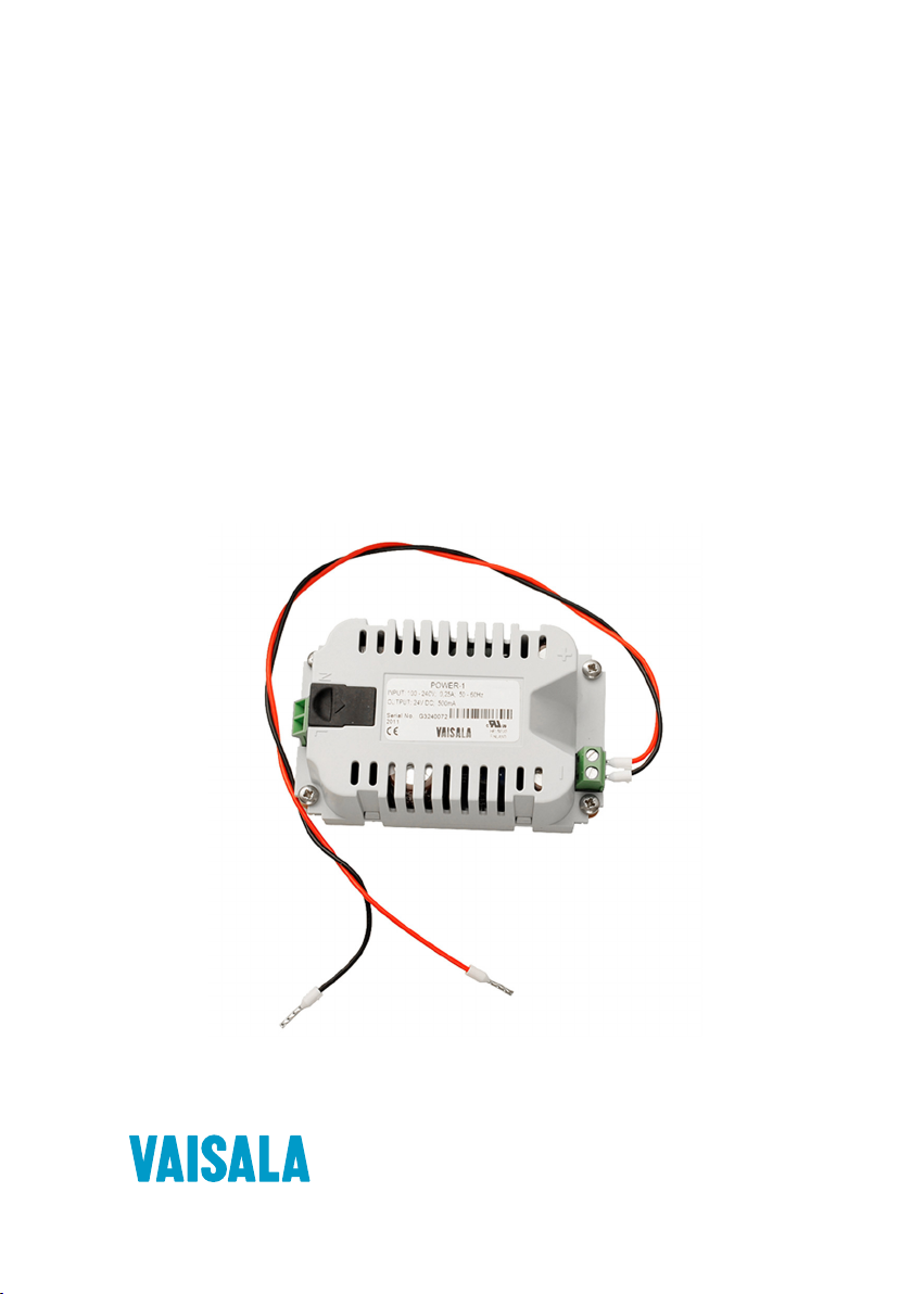
POWER-1 Power Supply Module
Input terminals
for connecting
AC mains voltage
Terminals for
DC output
Product overview
POWER-1 power supply module is designed for installation in Vaisala transmitters HMT330,
DMT340, MMT330, PTU300, and PTB330. See the User Guide of your transmitter for details.
The POWER-1 spare part item contains the following parts:
The spare part item can optionally be ordered with a mains power cable (with US, AUS, EUR,
or UK plug) and cable gland (M20×1.5).
Figure 1 POWER-1 power supply module
Table 1 POWER-1 specifications
Operating voltage 100 … 240 VAC, 50/60 Hz, 300 mA
Output 24 DC, 500 mA
Connections
Operating temperature −40 … +60 °C (−40 … +140 °F)
Operating humidity 0 … 100 %RH
Outdoor use Yes, inside an IP65 rated closure
Storage temperature −40 … +70 °C (−40 … +158 °F)
Mains power cable temp. rating ≥ +75 °C (+167 °F)
Required housing classification IP65
Overvoltage category II
Pollution degree 2
Operating altitude Max. 3000 m (9843 ft)
UL file number E249387
Electrical safety compliance Low Voltage Directive (2014/35/EU)
Manufacturer Vaisala Oyj, Vanha Nurmijärventie 21, FI-01670 Vantaa, FINLAND
• Power supply module
• Fastening screws (M3×8 DIN7985 PZ A4)
• Wires for connecting the power supply module to a transmitter’s power terminals
Screw terminals for 0.5 … 2.5 mm2 wire (20 … 14 AWG)
UL/IEC/EN/BS 61010‑1
Made in Finland
3
Page 4

Installation and wiring
110 [4]
80 [3]
10 [0.4]
mm
[in]
7 [0.3]
1
2
3
ollow the steps below to install the POWER-1 module and/or a mains power cable. If the
F
module and mains power cable have already been installed at Vaisala, these additional steps
are not required.
WARNING!
supply module only b
The mains power connection may be connected to the power
y an authorized electrician. A readily accessible
disconnect device must be incorporated in the fixed wiring.
WARNING!
• Do not detach the power supply module from the
transmitter when the power is on.
Do not connect the mains power to power supply module when it is not
•
installed in the transmitter.
• Always connect the protective ground terminal.
Preparing mains power cable
• Insulated ring terminal (size M4)
Cable cutters, cable-stripping pliers, crimping tool
•
If using a mains power cable not provided by Vaisala, prepare the cable for connection to the
wer supply input terminal.
po
Figure 2 Example of stripped mains power cable
Number in figure Wire Ring terminal size Min. … max. wire cross-section
1 Line N.a.
2 Neutral
3 Grounding M4
0.5 … 2.5 mm2 (20 … 14 AWG)
1. Strip approximately 110 mm (4 in) of the power cable's outer sheath to expose the wires.
2.
Cut the line and neutral wires to the length of approximately 80 mm (3 in). If you are
using a stranded wire, Vaisala recommends adding cable ferrules to the ends.
3. Leave the grounding wire 110 mm (4 in) long.
4. Crimp an insulated ring terminal (size M4) to the grounding wire.
4 M2106
24EN-C
Page 5

CAUTION!
3
1
2
Make sure that the grounding wire is longer than the line and
neutral wires. Under mechanical stress, the grounding wire must be the last to
disconnect from the protective ground terminal.
Installing POWER-1 module
1. Disconnect power from the transmitter and open the transmitter cover.
2. If necessary, install a cable gland or conduit fitting in the transmitter for the mains power
cable. Make sure the outer diameter of the cable is compatible with the cable gland or
conduit fitting used.
If the power supply module has already been installed at the factory and you are installing
just the mains power cable, continue from step 5.
3. Connect the wires from the power supply module's terminals marked with + and − to the
power terminals on the component board of the transmitter.
4. Fasten the power module to the bottom of the transmitter housing with 4 screws.
See the figure below for the orientation of the module.
5. Thread the mains power cable through the cable gland or conduit fitting.
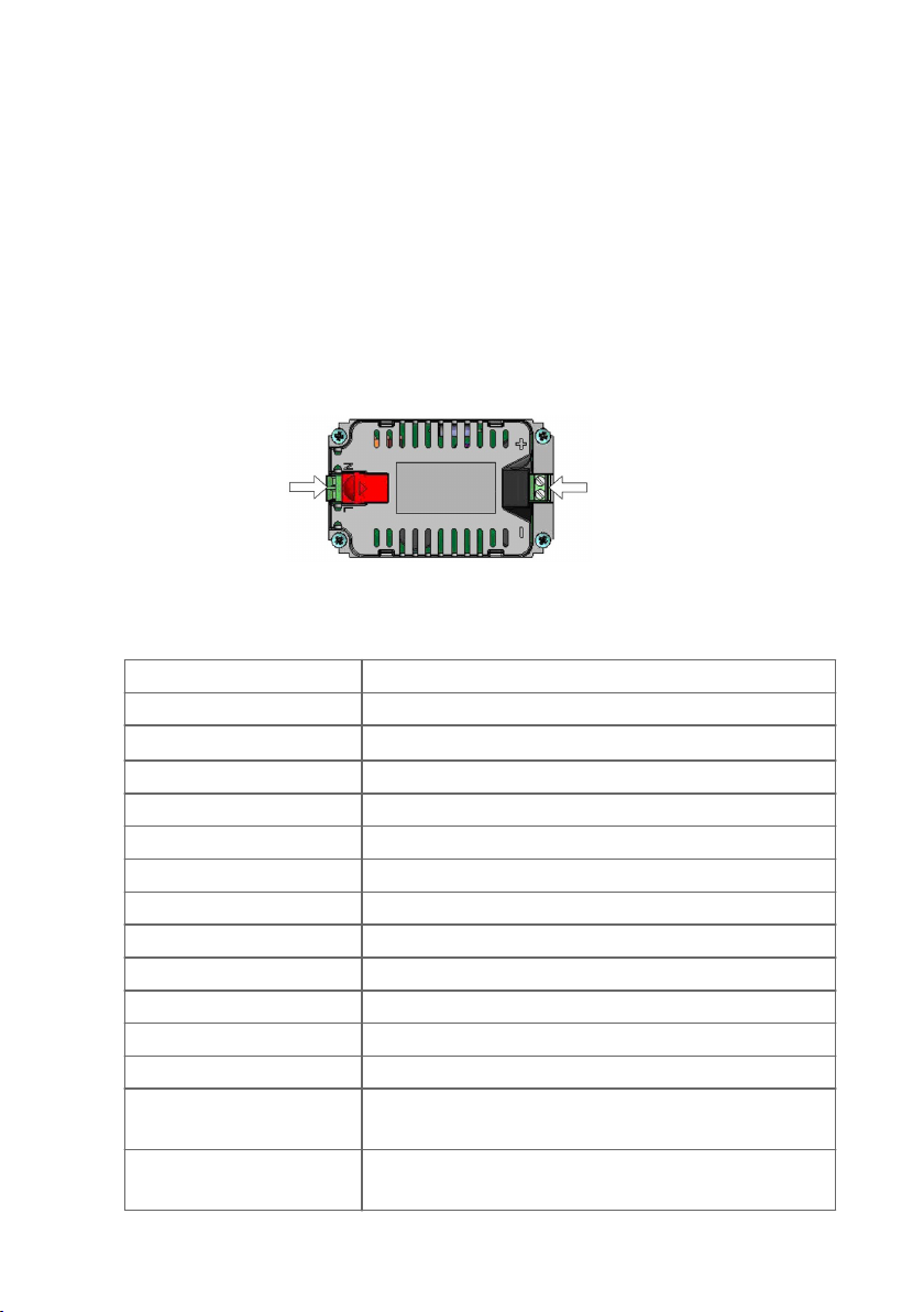
6. Connect the mains power wires to the power supply module terminals marked with
N and L.
7. Attach the grounding wire to the grounding terminal using the grounding screw and the
ring terminal at the end of the wire.
In the power cable supplied by Vaisala, the grounding wire is yellow-green.
8. Route the cable along the side of the module and tighten the cable gland (if used).
9. Close the cover. Connect power and verify that the transmitter starts up properly.
Grounding terminal and grounding
1
screw. Connect the grounding wire
here.
2 Grounding wire
3 Route the cable along the side of the
module
There are no serviceable parts in POWER-1 power supply module. If damaged, the
module can only be replaced with a new one.
5
Page 6

Warnings
Dieses Produkt entspricht der
Niederspannungsrichtlinie (2014/35/EU).
• Das Netzmodul darf nur von einem
dazu befugten Elektriker
angeschlossen werden.
• Trennen Sie das Netzmodul nicht vom
Messwertgeber, wenn der Strom
eingeschaltet ist.
• Verbinden Sie das Netzmodul nur mit
der Spannungsquelle, wenn es im
Messwertgeber HMT330/DMT340/
MMT330/PTU300/PTB330 montiert
ist.
• Das Erdungskabel muss zum Schutz
immer angeschlossen sein.
Ce produit est conforme à la Directive
relative à la Basse Tension (2014/35/UE).
• Seul un électricien compétent est
habilité à raccorder le module
d’alimentation au secteur.
• Ne pas détacher le module
d’alimentation du transmetteur
lorsqu’il est en service.
• Ne pas raccorder le secteur au module
d’alimentation lorsque celui-ci n’est pas
installé dans le transmetteur HMT330/
DMT340/MMT330/PTU300/PTB330.
• Toujours raccorder un bornier de
protection à la terre.
Tämä tuote on pienjännitedirektiivin
(2014/35/EU) mukainen.
• Vaihtovirtaliitännän saa kytkeä
tehonsyöttömoduuliin ainoastaan
valtuutettu sähköasentaja.
• Älä irrota tehonsyöttömoduulia
lähettimestä, kun virta on kytkettynä.
• Älä kytke verkkovirtaa
tehonsyöttömoduuliin, jos kyseistä
moduulia ei ole asennettu HMT330/
DMT340/MMT330/PTU300/PTB330lähettimeen.
• Kytke aina maadoitusliittimet.
Questo prodotto é conforme alla Direttiva
sul basso voltaggio (2014/35/UE).
• La conduttura elettrica puó essere
collegata al modulo di alimentazione
elettrica soltanto da un elettricista
autorizzato.
• Non staccare l´alimentazione elettrica
dal trasmettitore quando é acceso.
• Non collegare la corrente elettrica al
modulo di alimentazione elettrica se
non é installato nel trasmettitore
HMT330/DMT340/MMT330/PTU300/
PTB330.
• Collegare sempre il morsetto protettivo
a terra!
Dette produkt er i overensstemmelse med
direktivet om lavspænding (2014/35/EU).
• Netstrømskoblingen til må kun
tilsluttes strømforsyningsmodulet af en
autoriseret elinstallatør.
• Strømforsyningsmodulet må ikke
løsgøres fra senderen, mens
spændingen er sluttet til.
• Slut ikke netspændingen til
strømforsyningsmodulet, når det ikke
er installeret i HMT330/DMT340/
MMT330/PTU300/PTB330-senderen.
• Forbind altid den beskyttende
jordklemme!
Dit product voldoet aan de eisen van de
richtlijn 2014/35/EU
(Laagspanningsrichtlijn).
• De stroom kan aan de stroomtoevoer
module aangesloten worden alleen
door een bevoegde monteur.
• Het is niet toegestaan de
stroomtoevoer module van de
transmitter los te koppelen wanneer de
stroom aan is.
• Het is niet toegestaan de stroom aan
de stroomtoevoer module aan te
sluiten als deze niet in een HMT330/
DMT340/MMT330/PTU300/PTB330transmitter is gemonteerd.
• Altijd beschermend aardcontact
aansluiten!
6 M210624EN-C
Page 7

Denna produkt uppfyller kraven i
direktivet om lågspänning (2014/35/EU).
• Nätanslutningen
(växelströmsanslutningen) får bara
anslutas till strömförsörjningsmodulen
av en behörig elektriker.
• Ta inte loss strömförsörjningsmodulen
från mätaren när strömmen är på.
• Anslut inte strömförsörjningsmodulen
till nätet när den inte är installerad i
HMT330/DMT340/MMT330/PTU300/
PTB330-mätaren.
• Anslut alltid en skyddande
jordningsplint
See toode vastab madalpinge direktiivile
(2014/35/EL).
• Voolukaabli võib vooluallika mooduli
külge ühendada ainult volitatud
elektrik.
• Ärge ühendage vooluallika moodulit
saatja küljest lahti, kui vool on sisse
lülitatud.
• Ärge ühendage voolukaablit
vooluallika mooduli külge, kui seda
pole HMT330/DMT340/MMT330/
PTU300/PTB330-tüüpi saatjasse
paigaldatud.
• Ühendage alati kaitsev
maandusklemm!
Ez a termék megfelel a Kisfeszültségű
villamos termékek irányelvnek (2014/35/
EU).
• A hálózati feszültséget csak
feljogosított elektrotechnikus
csatlakoztathatja a tápegységmodulra.
• A bekapcsolt távadóról ne csatolja le a
tápegységmodult.
• Ne csatlakoztassa a hálózati
feszültséget a tápegységmodulhoz, ha
az nincs beépítve a HMT330/DMT340/
MMT330/PTU300/PTB330 távadóba.
• Feltétlenül csatlakoztasson földelő
védőkapcsot!
Este producto cumple con la directiva de
bajo voltaje (2014/35/UE).
• La conexión de la alimentación
principal al módulo de alimentación
sólo puede realizarla un electricista
autorizado.
• No desenchufe el módulo de
alimentación del transmisor cuando
esté encendido.
• No conecte la alimentación principal al
módulo de alimentación cuando no
esté instalado en el transmisor
HMT330/DMT340/MMT330/PTU300/
PTB330.
• Conecte siempre el terminal de
protección de conexión a tierra.
Šis produkts atbilst Zemsprieguma
direktīvai (2014/35/ES).
• Strāvas pieslēgumu var pieslēgt pie
barošanas avota moduļa tikai
autorizēts elektriķis.
• Neatvienot barošanas avota moduli no
raidītāja, kad pieslēgta strāva.
• Nepievienot strāvu barošanas avota
modulim, ja tas nav uzstādēts
HMT330/DMT340/MMT330/PTU300/
PTB330 raidītājā.
• Vienmēr pievienot aizsargājošu
iezemētu terminālu !
Ten produkt spełnia wymogi Dyrektywy
niskonapięciowej (2014/35/UE).
• Napięcie zasilające powinno zostać
podłączone do modułu zasilacza tylko
przez wykwalifikowanego elektryka.
• Nie wolno odłączać modułu zasilacza
od nadajnika, kiedy zasilanie jest
włączone.
• Nie wolno podłączać napięcia
zasilającego do modułu zasilacza,
kiedy nie jest on zamontowany w
nadajniku HMT330/DMT340/MMT330/
PTU300/PTB330.
• Zawsze należy podłączać
zabezpieczający zacisk uziemiający!
7
Page 8

Šis produktas atitinka direktyvą dėl
žemos įtampos prietaisų (2014/35/ES).
• Elektros tinklą su energijos tiekimo
moduliu sujungti gali tik įgaliotas
elektrikas.
• Niekada neišimkite energijos tiekimo
modulio iš siųstuvo, kai maitinimas yra
įjungtas.
• Jei energijos tiekimo modulis nėra
įmontuotas HMT330/DMT340/
MMT330/PTU300/PTB330 siųstuve,
nejunkite jo į elektros tinklą.
• Visada prijunkite prie apsauginės
įžeminimo jungties!
Tento výrobek vyhovuje Směrnici pro
nízké napětí (2014/35/EU).
• Připojení síťového napájení k
napájecímu modulu smí provádět
pouze oprávněný elektrikář.
• Neodpojujte napájecí modul od
snímače při zapnutém napájení.
• Nepřipojujte síťové napájení k
napájecímu modulu, pokud není
instalován ve snímači HMT330/
DMT340/MMT330/PTU300/PTB330.
• Vždy zapojte ochrannou zemnící
svorku!
8 M210624EN-C
Page 9

Technical support
Contact Vaisala technical support at helpdesk@vaisala.com. Provide at least the
following supporting information as applicable:
• Product name, model, and serial number
• Software/Firmware version
• Name and location of the installation site
• Name and contact information of a technical person who can provide further
information on the problem
For more information, see www.vaisala.com/support.
Maintenance and calibration services
Vaisala oers comprehensive customer care throughout the life cycle of our
measurement instruments and systems. Our factory services are provided
worldwide with fast deliveries. For more information, see www.vaisala.com/
calibration.
• Vaisala Online Store at store.vaisala.com is available for most countries. You
can browse the oering by product model and order the right accessories,
spare parts, or maintenance and calibration services.
• To contact your local maintenance and calibration expert, see
www.vaisala.com/contactus.
Warranty
For standard warranty terms and conditions, see www.vaisala.com/warranty.
Please observe that any such warranty may not be valid in case of damage due to normal wear
and tear, exceptional operating conditions, negligent handling or installation, or unauthorized
modifications. Please see the applicable supply contract or Conditions of Sale for details of the
warranty for each product.
Recycling
Recycle all applicable material.
Follow the statutory regulations for disposing of the product and packaging.
9
Page 10

www.vaisala.com
 Loading...