

Page 1

M211857EN-A
Installation
Guide
Vaisala Optimus™ DGA Monitor f
or Transformers
OPT100
DRAFT
24 May 2017
Page 2

PUBLISHED BY
Vaisala Oyj
Street address: Vanha Nurmijärventie 21, FI-01670 Vantaa, Finland
Mailing address: P.O. Box 26, FI-00421 Helsinki, Finland
Phone: +358 9 8949 1
Fax: +358 9 8949 2227
Visit our Internet pages at w
© Vaisala 2017
No part of this manual may be reproduced,
published or publicly displa
or by any means, electronic or mechanical
(including photocopying), nor may its
contents be modified, translated, adapted,
sold or disclosed to a third party without
prior written permission of the copyright
holder. Translated manuals and translated
portions of multilingual documents are
based on the original English versions. In
ambiguous cases, the English versions are
applicable, not the translations.
The contents of this manual are subject to
change without prior notice.
Local rules and regulations may vary and
they shall take precedence over the
information contained in this manual.
Vaisala makes no representations on this
manual’s compliance with the local rules
and regulations applicable at any given
time, and hereby disclaims any and all
responsibilities related thereto.
This manual does not create any legally
binding obligations for Vaisala towards
customers or end users. All legally binding
obligations and agreements are included
ww.vaisala.com.
yed in any form
exclusively in the applicable supply
c
ontract or the General Conditions of Sale
and General Conditions of Service of
Vaisala.
This product contains software developed
by Vaisala or third parties. Use of the
software is governed by license terms and
conditions included in the applicable
supply contract or, in the absence of
separate license terms and conditions, by
the General License Conditions of Vaisala
Group.
This product may contain open source
software (OSS) components. In the event
this product contains OSS components,
then such OSS is governed by the terms
and conditions of the applicable OSS
licenses, and you are bound by the terms
and conditions of such licenses in
connection with your use and distribution
of the OSS in this product. Applicable OSS
licenses are included in the product itself
or provided to you on any other applicable
media, depending on each individual
product and the product items delivered
to you.
Page 3

Table of Contents
1. About This Document........................................................................................ 5
1.1 Version Information............................................................................................... 5
2. Planning The Installation...................................................................................7
2.1 Installation Safety...................................................................................................7
2.2 Installation Phases................................................................................................. 8
2.3 Required Personnel................................................................................................8
2.4 Required Materials................................................................................................. 9
2.5 Recommended Tools........................................................................................... 10
2.6 Storing and Transporting the DGA Monitor....................................................... 11
2.7 Preparations for Reinstalling a DGA Monitor..................................................... 11
2.8 Installation Site Requirements............................................................................. 11
2.8.1 Installation Location of DGA monitor...........................................................11
2.8.2 Recommended Locations of Oil Connections............................................ 13
3. Mechanical Installation.....................................................................................15
3.1 Unpacking DGA Monitor......................................................................................15
3.2 Mounting with Ground Mounting Set.................................................................15
3.2.1 OPT100 Parts with Ground Mounting Set................................................... 17
3.2.2 OPT100 Dimensions with Ground Mounting Set........................................19
3.3 Mounting with Wall Mounting Set.....................................................................20
3.3.1 OPT100 Parts with Wall Mounting Set........................................................22
3.4 Installing the Oil Lines.........................................................................................23
3.5 Attaching the Power Supply Unit...................................................................... 24
3.6 Attaching the Radiation Shield.......................................................................... 25
Table of Contents
4. Electrical Installation........................................................................................27
4.1 Cable Glands and Connectors............................................................................ 27
4.2 Grounding the DGA Monitor.............................................................................. 28
4.3 Connecting DC Power to DGA Monitor.............................................................29
4.4 Connecting Relay Control to Power Supply Unit..............................................31
4.5 Connecting RS-485............................................................................................. 33
4.6 Connecting Ethernet........................................................................................... 35
4.7 Connecting Relays...............................................................................................36
4.8 Connecting AC (Mains) Power........................................................................... 38
4.9 Verifying Tightness of Cable Glands.................................................................40
5. Commissioning...................................................................................................43
5.1 Turning On the DGA Monitor............................................................................. 43
5.2 Connecting to the User Interface...................................................................... 43
5.3 Initializing the DGA Monitor...............................................................................44
5.4 Starting Measurement Mode..............................................................................45
5.5 Finalizing the Installation....................................................................................45
6. Installation
6.1 Installation Checklist........................................................................................... 47
6.2 Safety Checklist................................................................................................... 48
Technical Support
Warranty......................................................................................................................... 51
Verification...................................................................................47
.......................................................................................................51
Recycling........................................................................................................................51
1
Page 4

OPT100 Installation Guide M211857EN-A
List of Figures
Figure 1 Possible Locations of Oil Connections..........................................................13
Figure 2 Assembly of the Mounting Stand...................................................................16
Figure 3 OPT100 Front Parts with Ground Mounting Set........................................ 17
Figure 4 OPT100 Rear Parts with Ground Mounting Set..........................................18
Figure 5 OPT100 Dimensions with Ground Mounting Set....................................... 19
Figure 6 OPT100 Front Parts with Wall Mounting Set..............................................22
Figure 7 OPT100 Rear Parts with Wall Mounting Set...............................................22
Figure 8 OPT100 DGA Monitor Cable Glands and Connectors..............................27
Figure 9 OPTPSU1 Power Supply Unit Cable Glands and Connectors.................28
Figure 10 Terminal Block Y3 Wiring................................................................................ 29
Figure 11 Terminal Block X5 Wiring................................................................................ 30
Figure 12 Terminal Block Y2 Wiring................................................................................ 32
Figure 13 Terminal Block X4 Wiring................................................................................ 33
Figure 14 Terminal Block Y1 Wiring Example................................................................35
Figure 15 Terminal Block X3 Wiring for Normally Open (NO) Relay
Connection...........................................................................................................37
Figure 16 Terminal Block X1 Wiring.................................................................................40
2
Page 5

List of Tables
Table 1 Document Versions.................................................................................................5
Table 2 Terminal Block Y3 Wiring....................................................................................29
Table 3 Terminal Block X5 Wiring....................................................................................30
Table 4 Terminal Block Y2 Wiring.................................................................................... 32
Table 5 Terminal Block X4 Wiring....................................................................................33
Table 6 Terminal Block Y1 Wiring..................................................................................... 35
Table 7 Terminal Block X3 Wiring.................................................................................... 37
Table 8 Terminal Block X1 Wiring....................................................................................40
List of Tables
3
Page 6

OPT100 Installation Guide M211857EN-A
4
Page 7

1. About This Document
1.1 Version Information
Table 1 Document Versions
Document Code Date Description
M211857EN-A - First version.
Chapter 1 – About This Document
5
Page 8

OPT100 Installation Guide M211857EN-A
6
Page 9

Chapter 2 – Planning The Installation
2. Planning The Installation
2.1 Installation Safety
WARNING!
you encounter the following marking during installation, consult product
documentation to
have to be taken to avoid them:
WARNING!
adhere to local and state legislation and regulations.
WARNING!
regulations at all times.
Read the installation instructions carefully before installing the product. If
find out the nature of the potential hazards and any actions which
Only licensed experts may install electrical components. They must
Make sure that you prepare only de-energized wires.WARNING!
Keep away from live circuits. Operating personnel must observe safety
WARNING!
Verify the grounding before and after performing maintenance on the unit.
CAUTION!
documentation.
perform according to specification, or decreased equipment lifetime.
Ground the DGA monitor chassis as instructed in the wiring instructions.
Do not modify the DGA monitor or use it in ways not described in the
Modifications may lead to safety hazards, equipment damage, failure to
7
Page 10

OPT100 Installation Guide M211857EN-A
CAUTION!
heat up during normal operation. Avoid touching the hot surfaces and wear protective
gloves when working inside the enclosure. Whenever possible, allow the device to cool
down before starting the work.
Follow the safety regulations of the installation site.
The safety of any system incorporating this equipment is the responsibility of the
assembler.
Surfaces inside the DGA monitor that are marked with the symbol below
Wear protective eyewear and gloves.
2.2 Installation Phases
Perform the installation of the DGA monitor in the following phases:
• Planning
• Mechanical installation
• Electrical installation
• Commisioning
• Installation
These phases correspond to chapters of the Installation Guide. As part of the final
installation verification phase, use the provided installation checklists to make sure you have
done all of the required installation steps.
2.3
Installation of the DGA monitor requires two persons. While most of the installation and
commissioning tasks can be done by a single person, safe carrying and lifting of the DGA
monitor requires two persons.
Installers must have the necessary training to legally perform all required tasks. For example,
connecting the DGA monitor to mains power must be done by a licensed electrician.
Required Personnel
verification
8
Page 11

Applicable legislation and site safety guidelines may require additional personnel to be
present in the installation.
2.4 Required Materials
In addition to the items delivered by Vaisala, installation of the DGA monitor requires
various materials that you must supply yourself.
Items Delivered by Vaisala
• DGA Monitor (Vaisala item OPT100)
• DGA Monitor enclosure
• Swagelokâ fitting SS-10M0-61-6M (2 pcs)
• Protection shell for Ethernet connector
• Relay control cable (marked RELAY, Vaisala cable CBL210539)
• Enclosure key
• Power Supply Unit (Vaisala item OPT100PSU)
Chapter 2 – Planning The Installation
• Power Supply Unit enclosure
• DC power cable (Vaisala cable CBL210544)
• Enclosure key
Optional items (must have either Wall Mounting Set or Ground Mounting Set):
• Wall Mounting Set (Vaisala item OPTMSET1)
• Installation beam (2 pcs)
• Cradle for Power Supply Unit
• Screws and washers
• Ground Mounting Set (Vaisala item OPTMSET2)
• Mounting stand (delivered in three parts)
• Wedge anchors (6 pcs) for securing the mounting stand to ground
• Screws, washers, and nuts
• Radiation Shield (Vaisala item OPTSHLD1)
• Radiation shield (delivered in three parts)
• Screws and washers
DGA Monitor Installation and Commissioning
• Grounding cable with max 16 mm2 conductor. Enough to reach from the DGA monitor
and the power supply unit to the grounding point(s).
• AC power cable with 2.5 mm2 (AWG10) wires and 9 ... 16 mm external diameter. Must be
compliant with local regulations for mains power cables.
• Relay cable
• RS-485 cable
9
Page 12

OPT100 Installation Guide M211857EN-A
• Shielded outdoor Ethernet cable with a RJ-45 connector for the permanent Ethernet
connection
• Laptop computer with:
• RJ-45 Ethernet connector
• Web browser (Google Chrome, Microsoft Internet Explorer, or Mozilla Firefox)
• Ethernet cable with RJ-45 connectors for temporary use
Oil Pipe Construction
The amount of required oil pipe construction materials depends on the intended pipe
length. Two pipes are needed, one for intake and one for returning the oil. Using the
recommended pipe material, the maximum allowed length of a single pipe is 10 m (33 ft). If
you are using a smaller pipe (minimum inner diameter 4 mm (0.157 in)), the maximum
length is 5 m (16 ft).
• Recommended oil pipe material: stainless steel pipe with 10 mm (0.393 in) outer
diameter, at least 6 mm (0.24 in) inner diameter. Enough to connect the inlet and outlet
valves to the DGA monitor.
• Adapters for connecting the oil pipes to the valves on the transformer
• Adapters for connecting the oil pipes to the DGA monitor (if not using recommended
oil pipe size). For 3/8 inch pipe, use Swagelokâ adapter SS-600-R-10M.
• Pipe
• Pipe supports
• Oil pipe insulation (if necessary)
• Oil absorption material for controlling possible leaks
• Rags for wiping
fittings for joining pipe sections
o oil
Other
• Personal safety equipment as required by installation site and applicable legislation
2.5
Hand Tools
Tools for Oil Pipe Construction
Recommended Tools
• Screwdrivers with slotted and Phillips heads
• Wrenches of various sizes
• Socket wrench and socket set
• Hex keys
• Cutting tools
• Cable stripping tool
• Metal
• Measuring tape
• Impact drill and bits
• Bubble level
• Multimeter
file
• Pipe bending tool
10
Page 13

Chapter 2 – Planning The Installation
• Pipe cutting tool
• Pipe deburring tool
• Pressurized air, either a bottle or a compressor
• Degreasing cleaning spray
• Container for waste oil (at least 5 liter capacity)
2.6 Storing and Transporting the DGA Monitor
Keep the DGA monitor and any installation accessories in their original packaging during
storage and transport. Keep the items dry and in conditions allowed by the storage
specification. Honor any handling instructions marked on the outside of the packaging.
After installation, store the packaging in a dry place. You can reuse it if the DGA monitor is
stored and/or transported again.
2.7 Preparations for Reinstalling a DGA
Monitor
If you want to relocate an already installed DGA monitor, you must prepare it for transport
and reinstallation by following the uninstallation procedure. See OPT100 User Guide for
details.
2.8
DGA monitor can be installed and successfully operated in a wide variety of environments.
Operation in cold environments may require trace heating elements and thermal insulation
to be placed over the exposed sections of the oil pipes. If you have any questions, contact
Vaisala for more information.
2.8.1 Installation Location of DGA monitor
Installation Site Requirements
Performing a site inspection in person is a good idea. Take photographs of the intended
installation location, oil connections, and electrical connections. Measure the amount of
cable and oil pipe needed.
The DGA monitor can be attached to the transformer chassis or to its immediate vicinity. The
location must
• The location must be close to the oil connections to minimize the length of the oil lines.
The maximum length of the lines is 10 m (33 ft) each.
• The location must be safely accessible from the floor without the need to climb or
reach.
fulfill the following requirements:
11
Page 14

OPT100 Installation Guide M211857EN-A
• There must be enough room and suitable supporting structures to install the DGA
monitor in a vertical orientation. The DGA monitor must not be tilted more than 5
degrees.
• If the Ground Mounting Set will be used to install the DGA monitor, there must be a
level concrete surface that is at least 100 mm thick.
If you have many suitable locations, prefer the following:
• Locations that are protected from rain and solar radiation.
• Locations where the vibration and heat from the transformer are not directly conducted
to the DGA monitor.
12
Page 15

2
3
4
5
1
Chapter 2 – Planning The Installation
2.8.2 Recommended Locations of Oil Connections
You must build two oil lines between the DGA monitor and the transformer: one for intake of
fresh oil, and an outlet line for returning the measured oil. Make sure you have appropriate
adapters for connecting the oil lines to the valves. The maximum allowed length of an oil line
is 10 m (33 ft). The location of oil connections on the transformer impacts the performance
of the DGA monitor.
Figure 1 Possible Locations of Oil Connections
1 Oil reservoir. Not recommended.
2 Side of the oil tank, top level. Good for returning the measured oil.
3 Side of the oil tank, high enough from the bottom to enable proper oil movement. Good
for oil intake. Moisture response time is moderate depending on the oil volume.
4 Straight section in the radiator’s outlet pipe. Good location if the pipe has guaranteed
oil flow.
Oil flow guarantees that the sampled oil is representative, and the cooling flow carries
the outlet oil from the monitor away from the inlet. Compared to the radiator inlet pipe,
oil in the outlet pipe is cooler, preventing unnecessary heating of the DGA monitor.
5 Drain valve of the oil tank. Not recommended.
Measurement response time is poor due to static oil flow. There is also risk of separated
water (leading to wrong results) and oil sludge (risk of sensor contamination and
clogged filter).
13
Page 16

OPT100 Installation Guide M211857EN-A
DGA monitor needs to pump oil in both directions during initialization and maintenance.
To make sure this is possible, check that:
• Intake and outlet valves are both below oil level in the transformer. There should be
no risk of drawing gas into the pipes even when the flow is reversed.
• There are no flow direction control valves on the oil lines.
14
Page 17

Chapter 3 – Mechanical Installation
3. Mechanical Installation
3.1 Unpacking DGA Monitor
• Wire cutters
Two persons are required to lift the DGA monitor out of the packaging.
1. Cut the packing straps and remove the cover.
2. Remove the top padding from the box.
3. Lift the DGA monitor out of the box and place it on a stable surface with the door
pointing up.
CAUTION!
on the bottom of the enclosure. When unpacking and moving the DGA monitor,
avoid putting the bottom of the DGA monitor on the ground. Putting the weight of
the unit on the cable glands and oil connections may damage them.
The cable glands and oil connections of the DGA monitor are located
3.2 Mounting with Ground Mounting Set
• Ground Mounting Set (Vaisala item OPTMSET2)
• Mounting stand (delivered in three parts)
• Wedge anchors (6 pcs) for securing the mounting stand to ground
• Screws, washers, and nuts
• 6 mm hex key
• 13 mm wrench
• Impact drill and bits
Use the Ground Mounting Set when a free standing installation of the DGA monitor is
needed. The mounting surface must allow the use of wedge anchors to secure the mounting
stand. A concrete surface that is at least 100 mm thick is recommended.
15
Page 18

3
2
1
4
OPT100 Installation Guide M211857EN-A
Figure 2 Assembly of the Mounting Stand
1 Mounting holes on the top are for attaching the DGA monitor.
2 Mounting holes on the side join the parts of the mounting stand together.
3 Holes on the bottom (three on each side) are for anchoring the mounting stand to the
ground.
4 Attach the power supply unit to the middle part using these four holes.
1. Assemble the mounting stand. Tighten the screws to finger tightness at this point, not
all the way.
2. Using the assembled mounting stand as the template, mark the locations of the six
anchors on the mounting surface.
3. Drill holes for the anchors using an impact drill and an 8 mm drill bit. The holes must be
60 mm deep.
4. Install the anchors in the holes.
5. Verify that the mounting stand is securely anchored.
6. Attach the mounting stand to the anchors.
16
Page 19

7. Attach the DGA monitor to the top of the mounting stand.
1
2
3
4
5
6
8. Tighten the screws to 20 Nm tightness.
3.2.1 OPT100 Parts with Ground Mounting Set
Figure 3 OPT100 Front Parts with Ground
Mounting Set
1 Status LEDs
2 OPT100 DGA Monitor
3 Door lock (3 pcs)
4 Power Supply Unit
5 Door lock
6 Mounting stand
Chapter 3 – Mechanical Installation
17
Page 20

1
2
3
OPT100 Installation Guide M211857EN-A
Figure 4 OPT100 Rear Parts with Ground
Mounting Set
1 Radiation shield
2 Cable glands and oil connections for DGA
Monitor
3 Cable glands for power supply unit
18
Page 21

675 (26.6)
1630 (62.2)
453 (17.8)
Chapter 3 – Mechanical Installation
3.2.2 OPT100 Dimensions with Ground Mounting Set
Dimensions are in millimeters and inches (in brackets).
Figure 5 OPT100 Dimensions with Ground Mounting Set
19
Page 22

OPT100 Installation Guide M211857EN-A
3.3 Mounting with Wall Mounting Set
• Wall Mounting Set (Vaisala item OPTMSET1)
• Installation beam (2 pcs)
• Cradle for Power Supply Unit
• Screws and washers
• 6 mm hex key
1. Attach one of the installation beams to the mounting location, at a height where you
want the top of the OPT100 enclosure to be. Make sure it is securely attached from at
least two points, and can bear the full weight of the DGA monitor.
2. Attach the second installation beam at the height of the second set of mounting holes.
3. Attach screws with washers to the top mounting holes of each pair on the sides of the
OPT100 enclosure (four screws in total). Tighten them enough to safely bear the weight
of the enclosure but not all the way in. The second hole of each set must remain free at
this point.
4. With two people lifting, lift the OPT100 enclosure up and hang it from installation
beams by the screws. If the lower installation beam is not at the correct height, reattach it at the correct height before attempting this step again.
5. Tighten the four screws to secure the enclosure in place.
20
Page 23

Chapter 3 – Mechanical Installation
6. Add a second screw (with washer) below each of the installed screws, and tighten
them.
The enclosure is now secured to the installation beams by a total of eight screws. The
second set of mounting holes at the ends of the installation beam is used to secure the
radiation shield. They should remain free at this point.
21
Page 24

1
2
3
4
5
1
2
3
4
5
6
OPT100 Installation Guide M211857EN-A
3.3.1 OPT100 Parts with Wall Mounting Set
Figure 6 OPT100 Front Parts with Wall
Mounting Set
1 Status LEDs
2 OPT100 DGA Monitor
3 Door lock (3 pcs)
4 Power supply unit
5 Door lock
Figure 7 OPT100 Rear Parts with Wall
Mounting Set
1 Installation beam (upper)
2 Radiation shield
3 Installation beam
4 Cable glands for DGA Monitor
5 Cradle for Power supply unit
6 Cable glands for power supply unit
22
Page 25

3.4 Installing the Oil Lines
• Adapters for connecting the oil pipes to the valves on the transformer
• Adapters for connecting the oil pipes to the DGA monitor (if not using recommended
oil pipe size). For 3/8 inch pipe, use Swagelokâ adapter SS-600-R-10M.
• Recommended oil pipe material: stainless steel pipe with 10 mm (0.393 in) outer
diameter, at least 6 mm (0.24 in) inner diameter. Enough to connect the inlet and
outlet valves to the DGA monitor.
fittings for joining pipe sections
• Pipe
• Pipe supports
• Pipe bending tool
• Pipe cutting tool
• Pipe deburring tool
• Pressurized air, either a bottle or a compressor
• Degreasing cleaning spray
• Wrenches of various sizes
• Container for waste oil (at least 5 liter capacity)
Chapter 3 – Mechanical Installation
CAUTION!
the ground. Dirty parts may contaminate the transformer oil or cause connections to
leak.
If the DGA monitor is mounted using the wall mounting set, the power supply unit will be
attached by a mounting cradle. Make sure you are not routing the oil lines so that they will
obstruct the power supply unit attachment. See 3.5 Attaching the Power Supply Unit
(page 24).
When working with oil pipes and connectors, keep everything clean and
Wear protective eyewear and gloves.
o
If you are unsure which valves on the transformer to use for oil intake and return, see 2.8.2
Recommended Locations of Oil Connections (page 13).
1. Inspect the selected oil valves on the transformer. If there are any
flow direction control
valves previously installed, remove them. The DGA monitor needs to pump oil in both
directions during initialization, and this will not work if there are flow direction
controllers in the oil lines.
2. Clean the oil valves on the transformer from the outside and the inside. Use the
degreasing cleaning spray.
3. Install the adapters to the inlet and outlet valves on the transformer to match them to
the size of the oil pipe material.
23
Page 26

OPT100 Installation Guide M211857EN-A
4. Measure the distance from the oil valves to the DGA monitor, and plan the length and
shape of the oil pipe sections. Minimize the amount of joints.
5. Cut and bend the oil pipe to appropriate sections for building the oil lines.
6. Remove any sharp edges from the cut surfaces.
7. Clean any metal shavings from inside the pipes using pressurised air.
8. Build the oil lines between the valves and the oil connections on the DGA monitor
marked Oil In and Oil Out.
9. Remove the plugs from the oil connections on the DGA monitor and store them for
possible later use. Check that the oil connections are clean.
10. Connect both oil lines to the oil connections. Use the supplied adapters (delivered in a
separate bag) and read their instructions for use before making the connections.
a. Insert nut of the connector over the oil pipe.
b. Insert the two ferrules over the pipe.
c. Fully insert the pipe into the
fitting and against the shoulder; rotate the nut finger-
tight.
d. Hold the base of the connector with a second wrench to keep it from turning when
tightening.
e. Mark the nut position.
f. Tighten the nut one and one quarter turns with a wrench.
If you are not using the recommended oil pipe size, install adapters into the oil
connections
first. Then connect the oil pipe to the adapter.
11. Install pipe supports where necessary to support the pipe mechanically. The pipe
should be supported at least every two meters (six feet).
To verify that the oil connections are tight, check for leaks during commissioning when the
DGA monitor is pumping oil. Ideally, check the connections again after the DGA monitor
has been running for some time (for example, the next day).
3.5 Attaching the Power Supply Unit
• 6 mm hex key
1. If the Ground Mounting Set is used:
a. Attach the power supply unit to the middle of the mounting stand.
24
Page 27

Chapter 3 – Mechanical Installation
2. If the Wall Mounting Set is used:
a. Attach the power supply unit to the cradle.
b. Support the power supply unit and cradle and attach them to the bottom of the
OPT100 enclosure.
3.6 Attaching the Radiation Shield
• Radiation Shield (Vaisala item OPTSHLD1)
• Radiation shield (delivered in three parts)
• Screws and washers
1. Attach the radiation shield to the OPT100 enclosure:
a. Attach the left side panel. Note that the panels have an assigned side, they are not
identical.
b. Attach the right side panel.
c. Verify that all screws holding the side panels of the radiation shield are tight.
d. Attach the top panel.
25
Page 28

OPT100 Installation Guide M211857EN-A
26
Page 29

1 2 3 4 5 6 7
Chapter 4 – Electrical Installation
4. Electrical Installation
4.1 Cable Glands and Connectors
Figure 8 OPT100 DGA Monitor Cable Glands and Connectors
1 Oil Out: connection for oil return line
2 Oil In: connection for oil intake
3
4 RS-485: cable gland for RS-485 connection
5 Relay control out: cable gland for relay control to power supply unit
6 DC in: 24 VDC connection from power supply unit
7 Ethernet: external RJ-45 connector for permanent Ethernet connection
Ground terminal
27
Page 30

1 2 3 4 5 6 7
OPT100 Installation Guide M211857EN-A
Figure 9 OPTPSU1 Power Supply Unit Cable Glands and Connectors
1
Ground terminal
2 AC in: Mains power input. 100 ... 240 VAC, 50 ... 60 Hz, 10 A
3 Spare
4 Spare
5 Relay out: Relay output. Max 250 VAC, 10 A
6 Relay control in: Relay control from DGA monitor
7 DC out: DC out to DGA monitor. 24 VDC, 20 A
4.2 Grounding the DGA Monitor
• Grounding cable with max 16 mm2 conductor. Enough to reach from the DGA monitor
and the power supply unit to the grounding point(s).
• Cable stripping tool
• Metal
• Multimeter
1. Locate the ground terminals on the underside of the DGA monitor and the power
supply unit, and find a good grounding point on the transformer or the surrounding
structures.
file
2. Clean the grounding point of rust for a good connection.
3. Ground the DGA monitor:
a. Run a grounding cable from the ground terminal to the grounding point, and secure
it so it does not hang loose.
b. Connect the cable to the grounding point on the DGA monitor.
c. Connect the other end of the cable to the grounding point.
d. Measuring the resistance from the ground terminal to the grounding point to verify
the grounding.
4. Repeat step 3 to ground the power supply unit as well.
28
Page 31

24 VDC +
Ground
24 VDC -
+
-
BLK/RE D
BLK
GRN/YE L
Chapter 4 – Electrical Installation
4.3 Connecting DC Power to DGA Monitor
• DC power cable (Vaisala cable CBL210544)
• 3 mm slotted screwdriver
• Adjustable wrench
1. Open the cable gland marked DC in on the DGA monitor. Remove the plug and store it
for later use.
2. Insert the DC power cable through the outer nut and the seal insert, and start inserting
the cable through the cable gland. Stop when you reach the section of the cable where
the metal braid is exposed.
3. Bend the cable braid over the seal insert so that it will make contact with metal when
the cable gland is tightened.
4. Push the outer nut and the seal insert against the contact socket of the gland and
tighten the outer nut.
5. Inside the DGA monitor, connect the wires to terminal block Y3:
Table 2 Terminal Block Y3 Wiring
Signal Wire Color
Vaisala Cable CBL210544
24 VDC + Black with red marking +
24 VDC - Black -
Ground Green/yellow
Terminal
Figure 10 Terminal Block Y3 Wiring
29
Page 32

24 VDC +
Ground
24 VDC -
BLK/RE D
BLK
GRN/YE L
+ -
OPT100 Installation Guide M211857EN-A
6. Open the cable gland marked DC out on the power supply unit. Remove the plug and
store it for later use.
7. Insert the DC power cable through the outer nut and the seal insert, and start inserting
the cable through the cable gland. Stop when you reach the section of the cable where
the metal braid is exposed.
8. Bend the cable braid over the seal insert so that it will make contact with metal when
the cable gland is tightened.
9. Push the outer nut and the seal insert against the contact socket of the gland and
tighten the outer nut.
10. Inside the power supply unit, connect the wires to terminal X5:
Table 3 Terminal Block X5 Wiring
Signal Wire Color
Vaisala Cable CBL210544
24 VDC + Black with red marking +
24 VDC - Black -
Ground Green/yellow
Terminal
Figure 11 Terminal Block X5 Wiring
30
Page 33

Chapter 4 – Electrical Installation
4.4 Connecting Relay Control to Power
Supply Unit
• Relay control cable (marked RELAY, Vaisala cable CBL210539)
• 3 mm slotted screwdriver
• Adjustable wrench
1. Open the cable gland marked Relay control out on the DGA monitor. Remove the plug
and store it for later use.
2. Insert the relay control cable through the outer nut and the seal insert, and start
inserting the cable through the cable gland. Stop when you reach the section of the
cable where the metal braid is exposed.
3. Bend the cable braid over the seal insert so that it will make contact with metal when
the cable gland is tightened.
4. Push the outer nut and the seal insert against the contact socket of the gland and
tighten the outer nut.
31
Page 34

Relay 1
Relay 2
Relay 3
1 3 5
2 4 6
BRN
WHT
YEL
GRN
PNK
GRY
OPT100 Installation Guide M211857EN-A
5. Inside the DGA monitor, connect the wires to terminal block Y2:
Table 4 Terminal Block Y2 Wiring
Signal Wire Color
Vaisala cable CBL210539
Relay 1 control + White 1
Relay 1 control - Brown 2
Relay 2 control + Green 3
Relay 2 control - Yellow 4
Relay 3 control + Grey 5
Relay 3 control - Pink 6
Terminal
Figure 12 Terminal Block Y2 Wiring
6. Open the cable gland marked Relay control in on the power supply unit. Remove the
plug and store it for later use.
7. Insert the relay control cable through the outer nut and the seal insert, and start
inserting the cable through the cable gland. Stop when you reach the section of the
cable where the metal braid is exposed.
8. Bend the cable braid over the seal insert so that it will make contact with metal when
the cable gland is tightened.
9. Push the outer nut and the seal insert against the contact socket of the gland and
tighten the outer nut.
32
Page 35

BRN
WHT
YEL
GRN
PNK
GRY
Relay 1
Relay 2
Relay 3
2
1
9
8
7
6
5
4
3
Chapter 4 – Electrical Installation
10. Inside the power supply unit, connect the wires to terminal block X4:
Table 5 Terminal Block X4 Wiring
Signal Wire Color
Vaisala cable CBL210539
Relay 1 control + White 2
Relay 1 control - Brown 3
Relay 2 control + Green 5
Relay 2 control - Yellow 6
Relay 3 control + Grey 8
Relay 3 control - Pink 9
Terminal
Figure 13 Terminal Block X4 Wiring
4.5
Connecting RS-485
• RS-485 cable
• 3 mm slotted screwdriver
• Cable stripping tool
33
Page 36

OPT100 Installation Guide M211857EN-A
The default settings of the RS-485 line are:
• Serial settings 19200, 8, E, 1
• Modbus RTU slave
• MAC address 240
1. Open the cable gland marked RS-485 on the DGA monitor. Remove the plug and store
it for later use.
2. Prepare the cable for connection:
a. Measure how much cable you need to reach from the cable gland to terminal block
Y1.
b. Remove the outer sheath and cable braid from the part of the cable that will be left
inside the DGA monitor.
c. Strip the ends of the individual wires to expose the conductors for 1 cm (0.4 in).
d. Remove some more of the outer sheath to expose more cable braid. This part of the
braid should be connected to the cable gland.
3. Insert the cable through the outer nut and the inner seal, and start inserting the cable
through the cable gland. Stop when you reach the section of the cable where the metal
braid is exposed.
4. Arrange the cable braid so that it makes contact with the cable gland when it is closed.
Push the inner seal in place and tighten the outer nut.
34
Page 37

5. Inside the DGA monitor, connect the wires to terminal block Y1:
RS-485 +
RS-485 -
Common
1 3 5
2 4 6
BLU/WHT
BLU
BRN
Verify the wiring colors of your cable before making any connections.
Table 6 Terminal Block Y1 Wiring
Signal Terminal
RS-485 + 1
RS-485 - 3
Common 5
Chapter 4 – Electrical Installation
Figure 14 Terminal Block Y1 Wiring Example
4.6
Connecting Ethernet
• Shielded outdoor Ethernet cable with a RJ-45 connector for the permanent Ethernet
connection
• Protection shell for Ethernet connector
35
Page 38

OPT100 Installation Guide M211857EN-A
Ethernet connector ETH1 inside the DGA monitor is intended for temporary local use only.
For a permanent network connection, use the Ethernet connector under the DGA monitor.
1. Assemble the protection shell over the RJ-45 connector on your Ethernet cable.
Assemble according to Code A: see instructions on top of the bag that contains the
parts.
CAUTION!
rating of the enclosure.
You must use the protection shell to maintain the ingress protection
2. Open the plug marked Ethernet under the DGA monitor.
3. Plug in the Ethernet cable.
4. Tighten the connector by hand.
4.7 Connecting Relays
• Relay cable
• 3 mm slotted screwdriver
• Adjustable wrench
Maximum switching current of the relays:
• 6A (at 250VAC)
• 2 A (at 24 VDC)
• 0.2 A (at 250 VDC)
1. Open the cable gland marked Relay out on the power supply unit. Remove the plug
and store it for later use.
2. Prepare the cable for connection:
a. Measure how much cable you need to reach from the cable gland to terminal block
X3.
b. Remove the outer sheath and cable braid from the part of the cable that will be left
inside the power supply unit.
c. Strip the ends of the individual wires to expose the conductors for 1 cm (0.4 in).
d. Remove some more of the outer sheath to expose more cable braid. This part of the
braid should be connected to the cable gland.
36
Page 39

BRN
WHT
YEL
GRN
PNK
GRY
Relay 1
Relay 2
Relay 3
2
1
9
8
7
6
5
4
3
Chapter 4 – Electrical Installation
3. Insert the relay cable through the outer nut and the inner seal, and start inserting the
cable through the cable gland. Stop when you reach the section of the cable where the
metal braid is exposed.
4. Arrange the cable braid so that it makes contact with the cable gland when it is closed.
Push the inner seal in place and tighten the outer nut.
5. Inside the power supply unit, connect the wires to terminal block X3. Wire the
connection as normally open (NO) or normally closed (NC) according to the table
below.
Verify the wiring colors of your cable before making any connections.
Table 7 Terminal Block X3 Wiring
Signal Terminal
Relay 1 NC 1
Relay 1 common 2
Relay 1 NO 3
Relay 2 NC 4
Relay 2 common 5
Relay 2 NO 6
Relay 3 NC 7
Relay 3 common 8
Relay 3 NO 9
Figure 15 Terminal Block X3 Wiring for Normally Open (NO) Relay Connection
37
Page 40

OPT100 Installation Guide M211857EN-A
4.8 Connecting AC (Mains) Power
• AC power cable with 2.5 mm2 (AWG10) wires and 9 ... 16 mm external diameter. Must
be compliant with local regulations for mains power cables.
• Cable stripping tool
• 3 mm slotted screwdriver
• Adjustable wrench
WARNING!
adhere to local and state legislation and regulations.
WARNING!
regulations at all times.
WARNING!
cable gland marked AC in, you can use either of the two cable glands marked Spare
(diameter 5 ... 10 mm). If you are not wiring any relay outputs, you can also use cable
gland marked Relay out (diameter 7 ... 12 mm). If the AC in cable gland is left unused,
remember to plug it so that the enclosure remains tight.
If the power supply unit has no suitable cable gland free, you can replace the cable
gland marked AC in with a certified cable gland that is suitable for protecting the cable
and providing strain relief.
Only licensed experts may install electrical components. They must
Make sure that you prepare only de-energized wires.WARNING!
Keep away from live circuits. Operating personnel must observe safety
If the diameter of your mains power cable is not compatible with the
1. Install an external disconnection device for the AC power connection (for example, a
circuit breaker). Note the following:
• The disconnection device must be rated 16 A or 20 A at 250 VAC, and must conform
to any additional local regulations.
• The disconnection device must be visible from the DGA monitor, or lockable with a
key to prevent accidental switching on during installation and maintenance.
• The DGA monitor should not block access to the disconnection device after it has
been installed. The disconnection device should remain easy to operate.
2. Clearly mark the disconnection device as the disconnection device for the OPT100 DGA
Monitor.
38
Page 41

Chapter 4 – Electrical Installation
3. Make sure the external disconnection device is turned o. If possible, lock it in the o
position.
4. Run the AC cable between the external disconnection device and the power supply unit
of the DGA monitor.
5. Connect the AC cable to the external disconnection device.
6. Open the cable gland marked AC in on the power supply unit. Remove the plug and
store it for later use.
7. Prepare the cable for connection to the power supply unit:
a. Strip 14 cm (5.51 in) of the AC cable to expose the wires.
b. Cut
o 2 cm (0.79 in) of the line and neutral wires (brown and blue). Leave the green
and yellow grounding wire 14 cm (5.51 in) long.
CAUTION!
neutral wires. Under mechanical stress, the grounding wire must be the last to
disconnect from the protective ground terminal.
Make sure that the grounding wire is longer than the line and
c. Strip the ends of the individual wires to expose the conductors for 1 cm (0.4 in).
8. Insert the cable through the outer nut and the inner seal.
9. Start inserting the cable through the cable gland, and stop when the unstripped cable
is visible through the gland.
39
Page 42
Line
Neutral
Earth
BRN
BLU
GNR/YEL
L N
OPT100 Installation Guide M211857EN-A
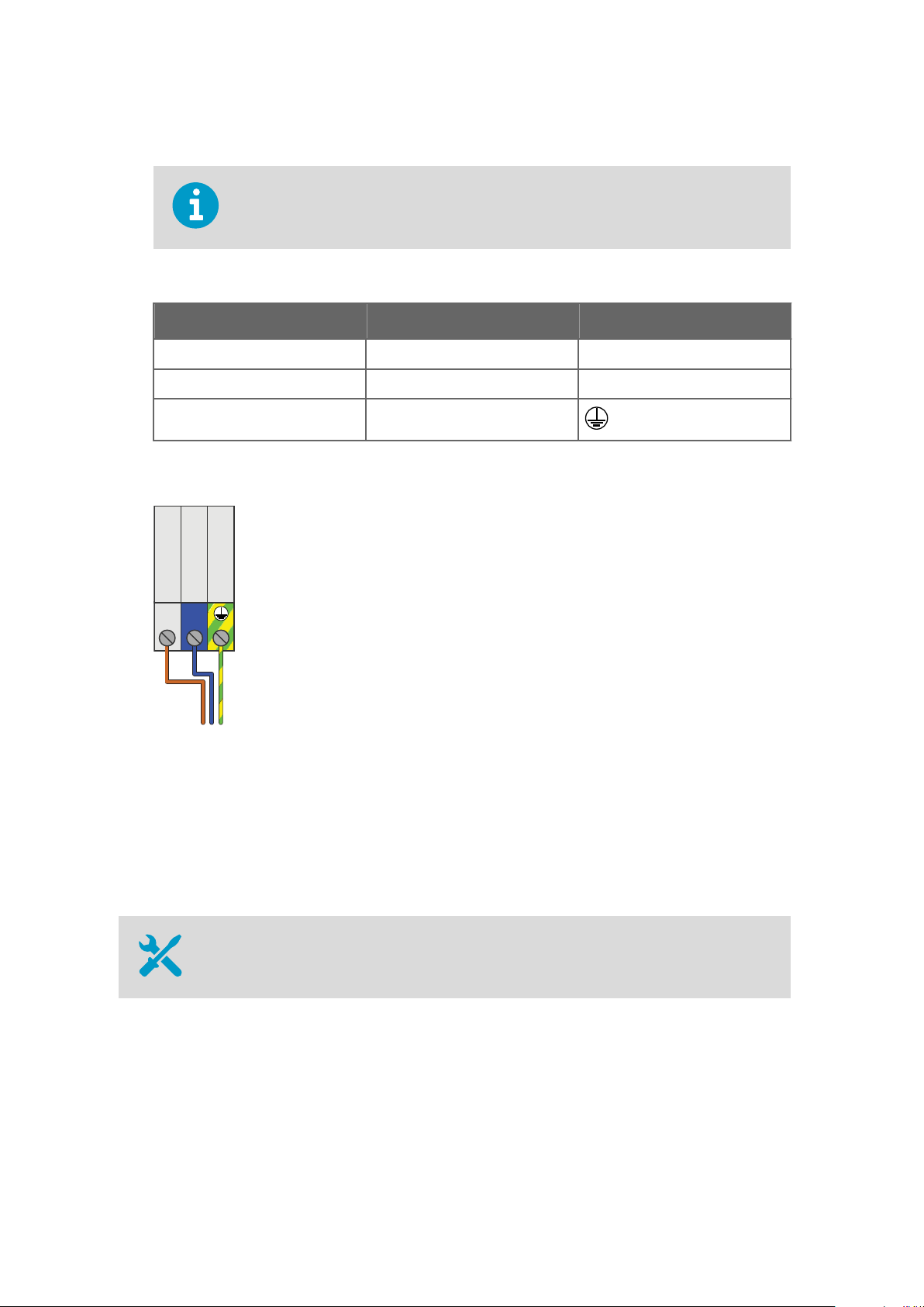
10. Inside the power supply unit, connect the wires to terminal block X1:
Wiring colors may be dierent depending on your cable.
Table 8 Terminal Block X1 Wiring
Signal Wire Color Terminal
Line Brown L
Neutral Blue N
Ground Green/yellow
Figure 16 Terminal Block X1 Wiring
11. Tighten the AC in cable gland. The cable gland is also the strain relief for the cable, so
make sure the gland holds the cable tight.
4.9
40
Verifying Tightness of Cable Glands
• Adjustable wrench
Page 43

Chapter 4 – Electrical Installation
To maintain enclosure tightness and provide strain relief to the cables, all cable glands on
the DGA monitor and the power supply unit must be tightened. Unused cable glands must
remain plugged.
1. Check every cable gland that is in use:
a. Pull on the cable slightly to verify that the cable is securely held by the cable gland.
b. Tighten the cable gland if the cable moves easily.
2. Check that every unused cable gland is plugged and tightened.
41
Page 44

OPT100 Installation Guide M211857EN-A
42
Page 45

Chapter 5 – Commissioning
5. Commissioning
5.1 Turning On the DGA Monitor
Verify that the DGA monitor is fully wired and grounded before turning it on.CAUTION!
1. Turn on AC power from the external disconnection device.
2. Turn on the circuit breaker F1 Main and switch S1 inside the power supply unit.
3. Check the DC OK LED on the power supply:
• If the LED is lit solid green, DC power to the DGA monitor is successfully turned on.
• If the LED keeps blinking, it is likely that the 24 VDC connection to DGA monitor is
wired incorrectly. Turn
attempting to power on the DGA monitor again.
o switch S1 and AC power, and correct the problem before
4. Turn on the circuit breaker Main inside the DGA monitor.
5. Turn on the circuit breaker Heat inside the DGA monitor.
5.2
Connecting to the User Interface
• Laptop computer with:
• RJ-45 Ethernet connector
• Web browser (Google Chrome, Microsoft Internet Explorer, or Mozilla Firefox)
• Ethernet cable with RJ-45 connectors for temporary use
• Administration password for your OPT100 DGA Monitor
1. Connect your computer to the same network as the DGA monitor. If you are connecting
locally, connect the network cable between your computer and the port marked ETH1
on the processing unit inside the DGA monitor.
2. Open a web browser on the computer, and enter the IP address of the DGA monitor in
the address bar:
• If you are connecting locally through the ETH1 port, the IP address is always
192.168.28.2.
• If you are connecting through the network meant for SCADA integration, use the IP
address that has been assigned to the DGA monitor.
3. Enter Admin as the user name.
43
Page 46

OPT100 Installation Guide M211857EN-A
4. Enter the unique administration password for this OPT100 DGA Monitor. The password
is included in the OPT100 delivery documentation.
5. Select Log in. The user interface opens in your browser.
5.3 Initializing the DGA Monitor
• 5 mm hex key
Before starting the initialization, make sure that:
• DGA monitor is fully installed and wired.
• All oil connections are completed.
• DGA monitor is turned on.
• You are connected to the user interface with a web browser.
You must have physical access to the DGA monitor enclosure and the oil valves on the
transformer. Do not try to perform the initialization remotely.
You can stop the initialization sequence at most phases by selecting Control > Cancel.
1. In the user interface, select Control.
2. Read the instructions on screen and verify that the DGA monitor is waiting to be
initialized.
3. Select Start to start the initialization sequence.
4. Turn the manual override switch 90° counterclockwise on the side of the bleed valve to
unlock it. Select OK when done.
5. Remove the pipe plug from the bleed valve using the 5 mm hex key. Select OK when
done.
6. Open the oil intake and outlet valves on the transformer and select OK .
7. Wait for the DGA monitor to
beginning of the filling, and assisted using the oil pump of the DGA monitor in the later
stage. The duration of this step depends on the oil pressure, viscosity, temperature, and
length of the oil lines.
8. When instructed to do so, replace the pipe plug on the bleed valve. Select Continue
when done.
fill with oil. Oil pressure from the transformer is used in the
9. The user interface informs you when the initialization is complete. The DGA monitor is
now in standby mode.
44
Page 47

Chapter 5 – Commissioning
5.4 Starting Measurement Mode
In the measurement mode the DGA monitor repeats the measurement cycle continuously.
Before starting the measurement mode, make sure that:
• DGA monitor has been successfully initialized and is currently in standby mode.
1. Start the measurement mode from Control > Start Measuring.
2. Wait for the
conditions, it may take up to 90 minutes.
3. After the
or inside the DGA monitor.
first measurement cycle to complete. Depending on the starting
first cycle has been completed, verify that there are no oil leaks in the oil pipes
The DGA monitor will warm up furing the
made during the warm-up cycles are not guaranteed to be within the accuracy
specification.
first three measurement cycles. Measurements
5.5 Finalizing the Installation
1. If you have connected the DGA monitor to a host system using the Ethernet or RS-485
connections, verify the availability of the measurement data from the host system.
2. Verify that you have performed all installation steps according to the 6.1 Installation
Checklist (page 47).
3. Before leaving the installation site, perform a safety check and lock up accoding to the
6.2 Safety Checklist (page 48).
45
Page 48

OPT100 Installation Guide M211857EN-A
46
Page 49

Chapter 6 – Installation Verification
6. Installation Verification
6.1 Installation Checklist
Fill in the checklist and save it to record the tasks you have carried out. Make copies of the
list when needed.
Installation Preparations
Recommended tools available
Required materials and installation accessories available
Installation site safety requirements met
DGA monitor installation location selected
Oil intake and outlet connection valves available
Data connection to host system available at the installation site
Mechanical Installation
DGA monitor installed to selected location
Installation is vertical and not tilted more than 5 degrees
Oil intake and outlet pipes built between connection valves and DGA monitor installation location
Oil pipes connected to DGA monitor and transformer's oil valves
Insulation installed over oil pipes (if needed)
Electrical Installation
Grounding cable installed between DGA monitor enclosure and grounding point
Grounding cable installed between power supply unit and grounding point
Mains power connected to power supply unit
DC power cable installed between DGA monitor and power supply unit
Data connection cable installed (RS-485 or Ethernet)
47
Page 50

OPT100 Installation Guide M211857EN-A
Electrical Installation
Relay control cable installed between DGA monitor and power supply unit
Relay connections made to power supply unit (if needed)
All unused cable glands blocked
Cable glands tightened
Commissioning
DGA monitor turned on
Oil intake and outlet connection valves open
Connection to service interface OK
Pipe plug removed from bleed valve
Manual bleed valve override open
DGA monitor initialization cycle completed
Pipe plug installed to bleed valve
Completed first measurement cycle
DGA monitor in measurement mode
Data connection to host system verified
6.2 Safety Checklist
Verify all items in this safety checklist after you have completed all installation steps.
Safety
Mechanical installation stable and secure
Oil pipe connections checked for leaks
No active alarms in user interface
48
Status LED on DGA monitor door is green
Mains power connection and protective grounding verified
Pipe plug in place over the bleed valve
DGA monitor housing closed and locked with all three locks
Page 51

Safety
Power supply unit housing closed and locked
DGA monitor installation location
Transformer
Inspection date
Inspected by
Chapter 6 – Installation Verification
Comments
49
Page 52

OPT100 Installation Guide M211857EN-A
50
Page 53

Technical Support
Contact Vaisala technical support at helpdesk@vaisala.com. Provide at least the following
supporting information:
• Product name, model, and serial number
• Name and location of the installation site
• Name and contact information of a technical person who can provide further
information on the problem
For more information, see www.vaisala.com/support.
Warranty
For standard warranty terms and conditions, see www.vaisala.com/warranty.
Please observe that any such warranty may not be valid in case of damage due to normal
wear and tear, exceptional operating conditions, negligent handling or installation, or
unauthorized
for details of the warranty for each product.
modifications. Please see the applicable supply contract or Conditions of Sale
Recycling
Recycle all applicable material.
Follow the statutory regulations for disposing of the product and packaging.
51
Page 54

OPT100 Installation Guide M211857EN-A
52
Page 55

Page 56

www.vaisala.com
 Loading...