

QUICK REFERENCE GUIDE
Vaisala SPECTRACAP®
Oxygen Transmitter OMT364
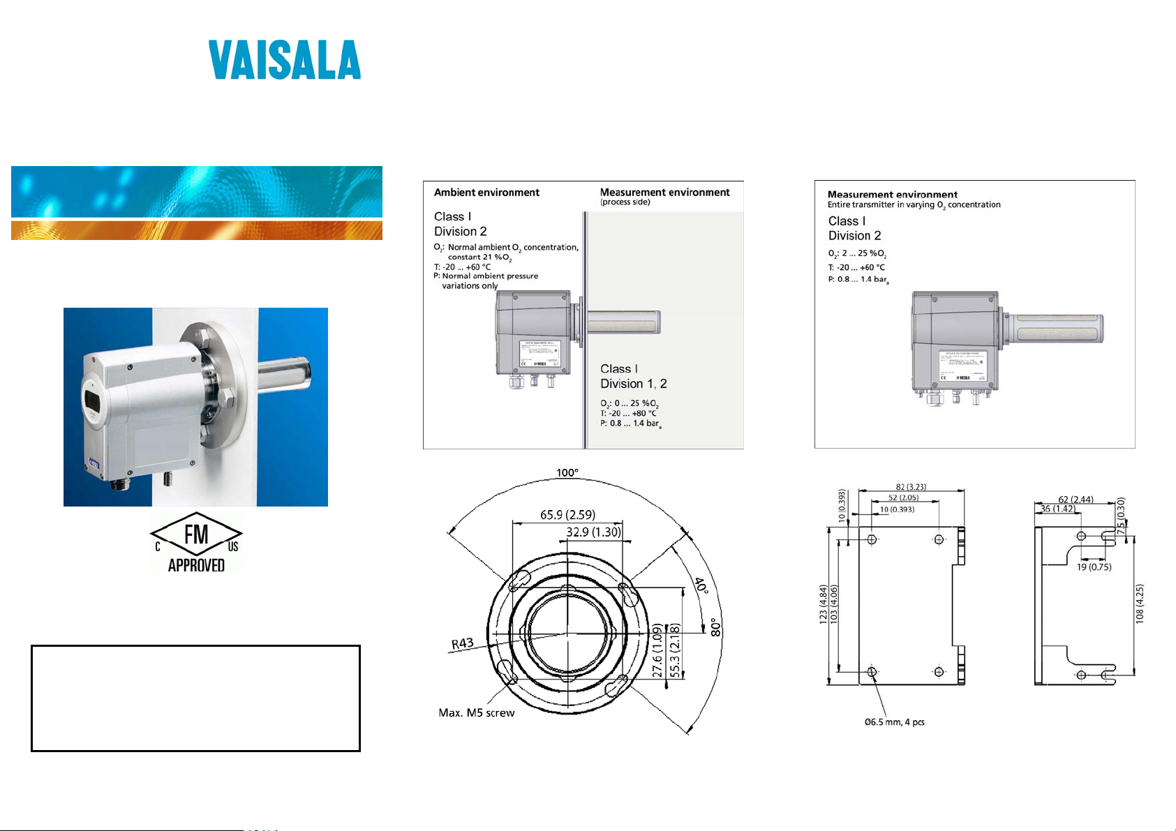
IN-LINE INSTALLATION
The maximum diameter of the OMT364 flange adapter is ø 97
mm. It has been chosen to suit to the center of a DIN 2572/B
flange (mounted with M16 hex bolts). The smallest possible
ANSI flange is ANSI 150 2.5" (mounted with 3/4" hex bolts).
Installation with probe pointing upwards prohibited. Installation
allowed only with probe horizontal or at a maximum of 45°
downward angle.
AMBIENT MEASUREMENT
Attach the wall mounting bracket to the desired location.
1.
Pre-fix the two outer M6 screws to the threads at the
2.
bottom of the transmitter
Attach the two inner screws as you place the transmitter
3.
on the wall mounting bracket.
Finish the installation by tightening all four screws.
4.
OMT364 Oxygen Transmitter is approved for Class I, Division
2, Groups A, B, C and D. Sensor for Class I, Division 1 and 2,
Groups A, B, C and D hazardous indoor and outdoor locations
with an enclosure rating IP66. Temperature class T4.
CAUTION OMT364 is a Class 1 laser product. Normal
handling and operation of the device is eyesafe because laser radiation is collimated and
maintained inside the probe. No laser
radiation is emitted outside the probe. Do not
place reflective surfaces directly into the
probe when the transmitter is in operation.
© Vaisala 2009. All rights reserved.
*M210901EN*
Figure 1 Flange Adapter Dimensions
Figure 2 Wall Mounting Bracket Dimensions
SAMPLE CELL INSTALLATION
WIRING
Open the front cover (never open the side cover) with the 3 mm
Allen key provided in the packing box to access the terminals.
In order to fulfill EMC requirements, the transmitter should be
connected to earth using the external terminal provided.
Installation notes:
Vin = 11 … 36 VDC, Pmax = 6 VA
For screw terminal connections use conductor AWG 20-16.
Always connect unpowered wires to transmitter to avoid
sparks on hazardous area. Make sure that Power ON switch
under yellow protective cover is in ON position before
making any wiring.
Install using Division 2 wiring methods as specified by the
NEC or CEC, as applicable.
WARNING Explosion hazard. Do not connect or
disconnect equipment when a flammable or
combustible atmosphere is present.
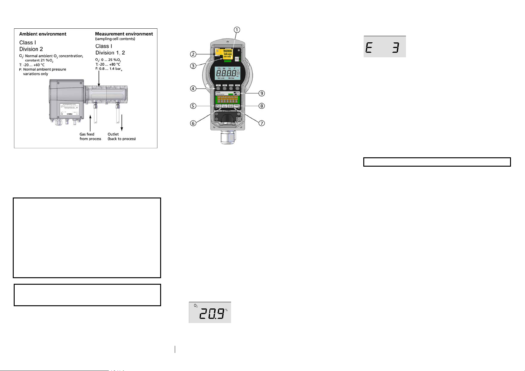
LOCAL INTERFACE LAYOUT
Figure 3 OMT364 Local Interface
1 = LED (red for startup or error, green for normal operation)
2 = Power ON/OFF switch (under the yellow tag)
3 = Service Port (RS-232) (under the yellow tag)
4 = Local interface keypad pushbuttons
5 = Supply voltage terminals
6 = Current output terminals
7 = RS-485 terminals
8 = Relay contact terminal
9 = RS-485 line termination jumper
STARTUP AND SELF-TEST SEQUENCE
Make sure that the power switch (located below the yellow
warning tag) is in the ON position, and attach the front cover
securely. Switch on the supply voltage.
After the self-test and warm-up are complete, oxygen
measurement starts. The entire start-up sequence takes
approximately 2.5 minutes.
Note that the transmitter may output some errors to the serial line
immediately after the self-test is over. These errors are expected.
No errors should remain active.
Figure 4 Oxygen Measurement Reading
If the self-test finds any errors, the error code is shown on the
display. Refer to the User’s Guide for the list of error codes.
Figure 5 Error Code on Display
USING THE DISPLAY/KEYPAD
The OMT364 has a local interface that can be accessed by
opening the front cover. The interface allows you to, for
example, view measurement information, enter compensation
parameters, perform calibration, and change the analog output
scaling. Refer to the User’s Guide for a full description.
To enter the menu, press the Up or Dn key. Use the Up and Dn
keys to scroll through the menu, and activate functions by
pressing the Ent key. To interrupt a function, use the Back key.
USING THE SERVICE PORT
WARNING Use the service port in safe area only.
The transmitter has an RS232C serial port for service functions.
Refer to the User’s Guide for connection cable options. If you
need to reconfigure device alarm level(s), Customer Interface or
other settings, the Service Interface provides a wider range of
options than the keypad and display functions.
Default serial communication settings are: Baud rate 19200,
8 data bits, no parity, 1 stop bit.
SERIAL COMMANDS
The list below provides some useful serial commands. Refer to
the User’s Guide for a full command list.
? Shows information about the device
CO2 Shows/sets CO2 for compensation
COXY1 Perform one-point adjustment
COXY2 Perform two-point adjustment
ERRS Shows detected errors
H2O Shows/sets H2O for compensation
HELP Lists commands
PRES Shows/sets pressure for compensation
R Starts continuous output
S Stops continuous output
SEND Sends measurement results
SIL Measures signal level
VERS Shows product name and software version
Visit our Internet pages at www.vaisala.com
Ref. M210901EN-A
 Loading...