

Page 1
M211435EN-J
User Guide
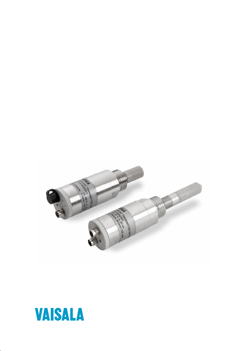
Vaisala DRYCAPâ Dew Point Transmitter
DMT143
Page 2

PUBLISHED BY
Vaisala Oyj
Vanha Nurmijärventie 21, FI-01670 Vantaa, Finland
P.O. Box 26, FI-00421 Helsinki, Finland
+358 9 8949 1
Visit our Internet pages at www.vaisala.com.
© Vaisala Oyj 2019
No part of this document may be
reproduced, published or publicly
displayed in any form or by any
means, electronic or mechanical
(including photocopying), nor
may its contents be modified,
translated, adapted, sold or
disclosed to a third party without
prior written permission of the
copyright holder. Translated
documents and translated
portions of multilingual
documents are based on the
original English versions. In
ambiguous cases, the English
versions are applicable, not the
translations.
The contents of this document are
subject to change without prior
notice.
Local rules and regulations may
vary and they shall take
precedence over the information
contained in this document.
Vaisala makes no representations
on this document’s compliance
with the local rules and
regulations applicable at any
given time, and hereby disclaims
any and all responsibilities related
thereto.
This document does not create
any legally binding obligations for
Vaisala towards customers or end
users. All legally binding
obligations and agreements are
included exclusively in the
applicable supply contract or the
General Conditions of Sale and
General Conditions of Service of
Vaisala.
This product contains software
developed by Vaisala or third
parties. Use of the software is
governed by license terms and
conditions included in the
applicable supply contract or, in
the absence of separate license
terms and conditions, by the
General License Conditions of
Vaisala Group.
Page 3

Table of Contents
Table of Contents
1. About This Document................................................................................... 7
1.1 Version Information..........................................................................................7
1.2 Related Manuals................................................................................................ 7
1.3 Documentation Conventions...........................................................................7
1.4 Trademarks........................................................................................................ 8
2. Product Overview...........................................................................................9
2.1 Introduction to DMT143 ...................................................................................9
2.2 Basic Features and Options...........................................................................10
2.2.1 Connectivity to Vaisala Insight Software................................................11
2.3 DMT143 and DMT143L Transmitter Parts...................................................... 12
2.3.1 DMT143 with G1/2” ISO228/1 Thread..................................................... 12
2.3.2 DMT143 with NPT Thread........................................................................ 13
2.3.3 DMT143L with G1/2” ISO228/1 Thread...................................................14
2.4 Loop-powered Display................................................................................... 14
2.5 Connection Cables...........................................................................................15
2.6 Sampling Accessories..................................................................................... 16
2.7 Safety................................................................................................................16
2.7.1 ESD Protection......................................................................................... 16
2.8 Regulatory Compliances.................................................................................17
3. Functional Description................................................................................ 18
3.1 DRYCAPâ Technology....................................................................................18
3.1.1 Autocalibration.........................................................................................18
3.1.2 Sensor Purge.............................................................................................18
3.1.3 Sensor Warming in High Humidities and Freezing Conditions.......... 19
3.2 DMT143 Startup Sequence............................................................................. 19
3.3 Alarm LED....................................................................................................... 20
1
Page 4

DMT143 User Guide M211435EN-J
4. Installation....................................................................................................... 22
4.1 Configuring Transmitter Before Installation................................................22
4.2 Selecting the Location...................................................................................22
4.3 Installing the Transmitter...............................................................................23
4.4 Wiring.............................................................................................................. 24
4.4.1 Power Supply Requirements................................................................. 25
4.5 Sampling from a Process............................................................................... 27
4.6 Sampling Accessories.................................................................................... 28
4.6.1 DMT242SC Sampling Cell.......................................................................28
4.6.2 DMT242SC2 Sampling Cell with Swagelok Connectors.....................28
4.6.3 DSC74 Sampling Cell with Quick Connector and Leak Screw........... 29
4.6.4 DSC74B Two-Pressure Sampling Cell...................................................30
5. Operation.........................................................................................................36
5.1 Transmitter Start-up.......................................................................................36
5.2 Vaisala Insight Software................................................................................ 36
5.2.1 Connecting to Insight Software.............................................................37
5.3 Operation with DM70 Handheld Dew Point Meter.....................................38
6. Modbus Communication...........................................................................40
7. Serial Communication................................................................................. 41
7.1 Connecting to the Serial Interface.................................................................41
7.2 Terminal Application Settings........................................................................41
7.3 Accessing Serial Interface in Devices with Modbus Output......................42
7.4 List of Serial Commands................................................................................43
7.5 Device Information.........................................................................................44
7.5.1 Show Device Information.......................................................................44
7.5.2 Show Analog Output Mode................................................................... 45
7.5.3 Show Firmware Version..........................................................................45
7.5.4 Show Firmware Information.................................................................. 45
7.5.5 Show Currently Active Errors................................................................46
7.5.6 Show Serial Number...............................................................................46
7.5.7 Show Command List...............................................................................46
7.6 Configuring Analog Output...........................................................................47
7.6.1 Set Analog Output Parameters and Scaling........................................47
7.6.2 Set Analog Output Error Notification...................................................48
7.6.3 Extend Analog Output Range............................................................... 49
7.6.4 Test Analog Output.................................................................................49
7.6.5 Enable or Disable Analog Output......................................................... 50
2
Page 5

Table of Contents
7.7 Serial Line Output Commands..................................................................... 50
7.7.1 Start Measurement Output....................................................................50
7.7.2 Stop Measurement Output.................................................................... 50
7.7.3 Set Output Interval................................................................................. 50
7.7.4 Output a Reading Once...........................................................................51
7.8 Configuring Measurement Parameters.........................................................51
7.8.1 Set Measurement Output Format.......................................................... 51
7.8.2 Set Measurement Filtering.....................................................................53
7.8.3 Set Pressure Compensation Value........................................................ 54
7.8.4 Select Unit................................................................................................ 55
7.8.5 View User Adjustment Parameters....................................................... 55
7.8.6 Set User Adjustment Parameters..........................................................56
7.9 Configuring Serial Line Operation................................................................ 57
7.9.1 Set Serial Line Operating Mode.............................................................57
7.9.2 Set Serial Line Settings........................................................................... 57
7.9.3 Set Transmitter Address.........................................................................58
7.9.4 Set Serial Line Response Time...............................................................59
7.10 Other Commands........................................................................................... 59
7.10.1 Opening the Transmitter in POLL Mode...............................................59
7.10.2 Closing the Connection to a Transmitter in POLL Mode....................59
7.10.3 Configure the Alarm LED.......................................................................60
7.10.4 Reset Transmitter.....................................................................................61
7.10.5 Restore Factory Settings.........................................................................61
8. Maintenance....................................................................................................62
8.1 Periodic Maintenance.....................................................................................62
8.1.1 Cleaning....................................................................................................62
8.1.2 Calibration................................................................................................62
8.1.3 Changing the Filter................................................................................. 62
8.1.4 Field Check Using DM70 Handheld Dew Point Meter.........................63
8.2 Repair Maintenance........................................................................................65
9. Troubleshooting............................................................................................66
9.1 Solving Typical Problems..............................................................................66
9.2 Error Messages in Insight Software..............................................................67
9.3 Error Codes in MI70 Handheld Meter...........................................................67
9.4 Unknown Serial Settings............................................................................... 68
10. Technical Data................................................................................................69
10.1 DMT143 Specifications................................................................................... 69
10.2 Dimensions...................................................................................................... 72
10.3 Spare Parts and Accessories......................................................................... 73
3
Page 6

DMT143 User Guide M211435EN-J
Appendix A: Modbus Reference................................................................. 75
A.1 Default Communication Settings..................................................................75
A.2 Function Codes...............................................................................................75
A.3 Data Encoding.................................................................................................75
A.3.1 32-Bit Floating Point Format................................................................. 75
A.3.2 16-Bit Integer Format..............................................................................76
A.4 Modbus Registers........................................................................................... 76
A.4.1 Measurement Data Registers.................................................................77
A.4.2 Status Registers.......................................................................................77
A.4.3 Configuration Registers..........................................................................78
A.4.4 Test Value Registers................................................................................80
A.4.5 Device Identification Objects................................................................ 80
A.5 Modbus Communication Examples...............................................................81
Warranty............................................................................................................ 85
Technical Support............................................................................................85
Recycling...........................................................................................................85
4
Page 7

List of Figures
Figure 1 DMT143 Parts – Model with ISO Thread.....................................................12
Figure 2 DMT143 Parts – Model with NPT Thread....................................................13
Figure 3 DMT143L Parts .................................................................................................14
Figure 4 Nokeval 301 Loop-powered Display........................................................... 15
Figure 5 DMT143 Startup Sequence...........................................................................20
Figure 6 DMT143 Digital and Analog Connectors...................................................25
Figure 7 Wiring the Digital Connector.......................................................................25
Figure 8 Wiring the Analog Connector......................................................................25
Figure 9 Example of Current Consumption During Purge...................................26
Figure 10 Example of Current Consumption During Autocalibration................. 27
Figure 11 Sampling Cells DMT242SC2 (left) and DMT242SC (right)..................29
Figure 12 DSC74 Sampling Cell with Accessories.................................................... 30
Figure 13 DSC74B............................................................................................................... 31
Figure 14 Removing the Leak Screw............................................................................ 32
Figure 15 Default Assembly of DSC74C.......................................................................33
Figure 16 Alternative Assembly of DSC74C (for Tight Spaces)............................34
Figure 17 DM240FA with DMT143................................................................................. 35
Figure 18 Settings Menu.................................................................................................. 38
Figure 19 Measurement Settings Menu....................................................................... 38
Figure 20 DMT143 Dimensions – Model with ISO Thread........................................72
Figure 21 DMT143 Dimensions – Model with NPT Thread...................................... 72
Figure 22 DMT143L Dimensions..................................................................................... 73
List of Figures
5
Page 8

DMT143 User Guide M211435EN-J
List of Tables
Table 1 Document Versions (English)...........................................................................7
Table 2 Related Manuals...................................................................................................7
Table 3 Output Parameters of the DMT143.................................................................9
Table 4 Alarm LED States..............................................................................................20
Table 5 Connector Pinouts............................................................................................ 24
Table 6 Default Modbus Serial Communication Settings.....................................40
Table 7 Default Serial Interface Settings....................................................................41
Table 8 List of Serial Commands................................................................................. 43
Table 9 Error Messages on ERRS Command............................................................46
Table 10 FORM Command Parameters ....................................................................... 52
Table 11 FORM Command Modifiers............................................................................ 52
Table 12 Pressure Conversion Coecients................................................................. 55
Table 13 Selection of Output Modes.............................................................................57
Table 14 Troubleshooting Table.....................................................................................66
Table 15 Error Messages in Insight Software..............................................................67
Table 16 Error Codes in MI70..........................................................................................67
Table 17 Measurement Performance............................................................................69
Table 18 Operating Environment...................................................................................70
Table 19 Inputs and Outputs...........................................................................................70
Table 20 Mechanical Specifications................................................................................71
Table 21 Compliance.......................................................................................................... 71
Table 22 Spare Parts and Accessories..........................................................................73
Table 23 Default Modbus Serial Communication Settings......................................75
Table 24 Modbus Function Codes..................................................................................75
Table 25 16-bit Signed Integer Format Details...........................................................76
Table 26 Modbus Measurement Data Registers (Read-Only)................................77
Table 27 Modbus Status Registers (Read-Only)........................................................77
Table 28 Error Codes on Modbus Interface.................................................................78
Table 29 Modbus Configuration Data Registers (Writable)................................... 78
Table 30 Modbus Test Registers (Read-Only)........................................................... 80
Table 31 Device Identification Objects........................................................................ 80
6
Page 9
Chapter 1 – About This Document
1. About This Document
1.1 Version Information
This manual provides information for installing, operating, and maintaining Vaisala DRYCAPâ
De
Table 1 Document Versions (English)
1.2 Related Manuals
t Transmitter DMT143.
wpoin
Document Code Date Description
M211435EN-J February 2019 This manual. Modbus protocol added. Added information about
M211435EN-H June 2017 Previous version. DRYCAPâ 180S sensor option for DMT143L
M211435EN-G January 2017 New probe model DMT143L (DMT242 replacement with
Vaisala Insight PC software. Removed the TIME command.
Added a cautionary note about changing stainless steel filter.
Updated section Troubleshooting
Specifications.
added. Analog output accuracy specification added. Accuracy
specification updated for DMT143L variant with DRYCAPâ
180M sensor. Filter spare part information updated.
DRYCAPâ 180M sensor) added. SF6 gas selections removed.
. Updated section DMT143
Table 2 Related Manuals
Document Code Name
M010091EN Vaisala DRYCAP
M211434EN Vaisala DRYCAPâ Dew Point Transmitter DMT143 Quick Guide
M211634EN Nokeval 301/302 Display Wiring Diagram
â
Handheld Dew Point Meter DM70 User's Guide
1.3 Documentation Conventions
WARNING!
follow instructions carefully at this point, there is a risk of injury or even death.
Warning alerts you to a serious hazard. If you do not read and
7
Page 10
DMT143 User Guide M211435EN-J
CAUTION!
follow instructions carefully at this point, the product could be damaged or
important data could be lost.
Note highlights important information on using the product.
Tip gives information for using the product more eciently.
Lists tools needed to perform the task.
Indicates that you need to take some notes during the task.
Caution warns you of a potential hazard. If you do not read and
1.4 Trademarks
Vaisalaâ and DRYCAPâ are registered trademarks of Vaisala Oyj.
Windowsâ is either a registered trademark or trademark of Microsoft Corporation in the
United States and other countries.
All other product or company names that may be mentioned in this publication are trade
names, trademarks, or registered trademarks of their respective owners.
8
Page 11

Chapter 2 – Product Overview
2. Product Overview
2.1 Introduction to DMT143
Vaisala DRYCAPâ Dew Point Transmitter DMT143 is a small and lightweight dew point
transmitter suitable for a wide range of OEM applications. DMT143 is easy to install and the
mechanics have been designed for harsh environments requiring protection against dust, dirt
and splashed water.
There are 2 variants of the DMT143 transmitter, DMT143 and DMT143L. DMT143 and DMT143L
oer dierent sensor, installation and output options to meet the requirements of varying dew
point measurement applications.
• DMT143 with DRYCAPâ 180D sensor
• either G1/2” ISO228/1 or NPT1/2” mechanical connection
• measurement range -70 ... +60 °C (-94 ... +140 °F)
• operating pressure up to 50 bara (725 psia)
•
voltage (V) or current (mA) analog output
• RS-485 digital output with Modbus RTU support
• DMT143L with DRYCAPâ 180M sensor
• G1/2” ISO228/1 mechanical connection
• measurement range -70 ... + 60 °C° (-94 ... +140 °F)
• operating pressure 0 ... 20 bara (0 ... 290 psia)
•
current (mA) analog output
1)
• RS-485 digital output with Modbus RTU support
• DMT143L with DRYCAPâ 180S sensor
• G1/2” ISO228/1 mechanical connection
• measurement range -50 ... + 60 °C° (-58 ... +140 °F)
• operating pressure 0 ... 20 bara (0 ... 290 psia)
• current (mA) analog output
1)
• RS-485 digital output with Modbus RTU support
The accuracies of the dierent sensors used in DMT143 and DMT143L have been optimized for
dierent parts of the sensors’ measurement ranges.
DMT143 transmitters use the Vaisala DRYCAPâ polymer sensor for dew point measurement.
DRYCAPâ technology has low maintenance needs due to its excellent long term stability and
durability against condensation. The calibration interval of DMT143 transmitters is 2 years.
1)
Table 3 Output Parameters of the DMT143
Parameter Abbreviation Metric Unit Non-Metric Unit
Dew point/frost point temperature T
Dew point/frost point temperature,
converted to atmospheric pressure
1) The analog output is not available in devices ordered with digital output only.
d/f
T
atm °C °F
d/f
°C °F
9
Page 12

DMT143 User Guide M211435EN-J
Parameter Abbreviation Metric Unit Non-Metric Unit
ppm moisture, by volume H20 ppm ppm
When dew point is below 0 °C, the transmitter outputs frost point for Td.
Dew point temperature in atmospheric pressure (T
presents the dew point the gas would have at atmospheric pressure. For this calculation to
provide accurate results, it is important to have the correct pressure setting stored in the
transmitter. This setting is specified on the order form, and it can be changed using the RS-485
line or DM70 handheld dew point meter.
More Information
‣
DMT143 and DMT143L Transmitter Parts (page 12)
‣
DMT143 Specifications (page 69)
2.2
Basic Features and Options
• Maximum dew point measurement range of -70 ... + 60 °C (-94 ... +140 °F)
• Dew point measurement accuracy up to ±2 °C (±5.4 °F) Td in air or N
• Operating pressure range:
• DMT143: 0 ... 50 bara (725 psia)
• DMT143L: 0 ... 20 bara (0 ... 290 psia)
• Configurable for optimum dew point measurement accuracy: Pressure compensation
(fixed pressure setting or live pressure input through RS-485)
• Analog output: one output channel, selectable from:
• 0 ... 1 V (DMT143 only)
• 0 ... 5 V (DMT143 only)
• 1 ... 5 V (DMT143 only)
• 4 ... 20 mA (DMT143 and DMT143L)
• None (DMT143 and DMT143L, digital output only)
• Digital output: RS-485 (non-isolated). The following protocols are supported:
• Modbus RTU
• Vaisala Industrial Protocol
• LED for dew point level alarm and transmitter diagnostics
• DRYCAPâ polymer sensor:
• Autocalibration ensures accuracy in changing measurement conditions
• Sensor warming keeps the sensor dry in high humidity
• Sensor purge ensures long term stability
• NIST traceable (certificate included)
• Field check suitability with DM70 handheld dew point meter
atm) is a calculated parameter that
d/f
2
10
Page 13

Chapter 2 – Product Overview
• Optional accessories:
• Stainless steel grid filter for vacuum applications
• Sampling cells with various installation options
• Loop-powered external display
• Connection cable for DM70 handheld dew point meter
• Plastic shipping case to avoid contamination during shipping
More Information
‣
Operation with DM70 Handheld Dew Point Meter (page 38)
‣
Modbus Communication (page 40)
‣
Connecting to the Serial Interface (page 41)
‣
DMT143 Specifications (page 69)
2.2.1 Connectivity to Vaisala Insight Software
The transmitter can be connected to Vaisala Insight software using a Vaisala USB cable (order
code 219690). With the Insight software, you can:
• See device information and status.
• See real-time measurement.
• Configure serial communication settings, filtering factor, alarm LED, and analog output
parameters and scaling.
More Information
‣
Connecting to Insight Software (page 37)
11
Page 14
1
2
3
4
5
6
7
8
DMT143 User Guide M211435EN-J
2.3 DMT143 and DMT143L Transmitter Parts
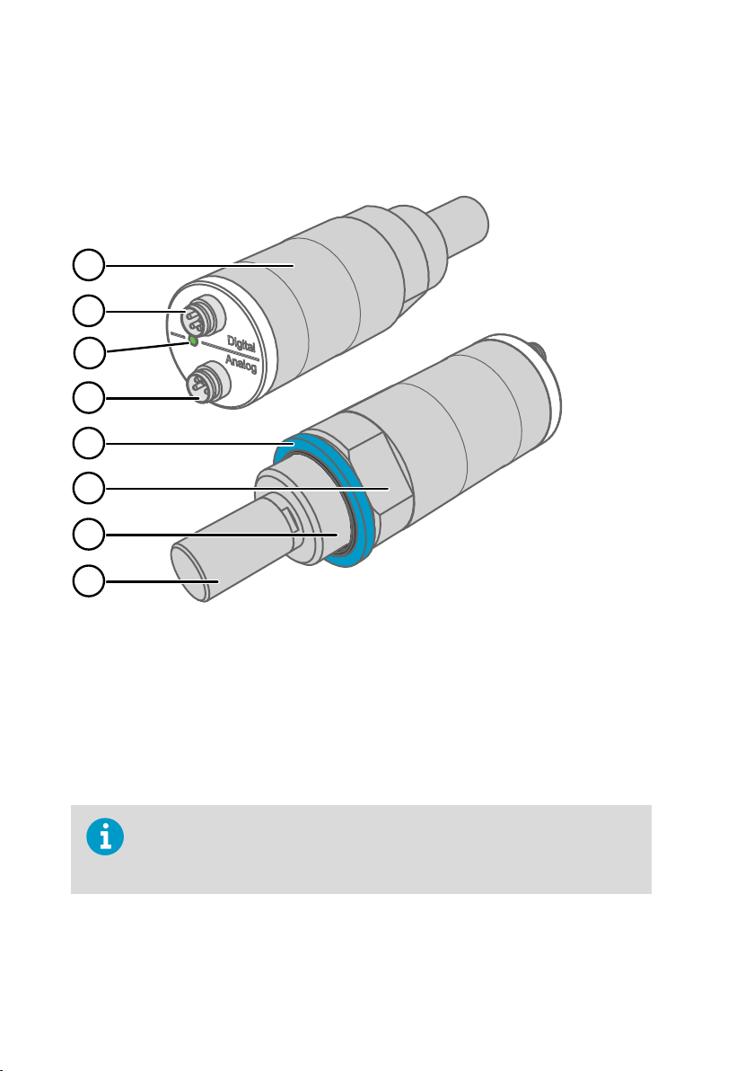
2.3.1 DMT143 with G1/2” ISO228/1 Thread
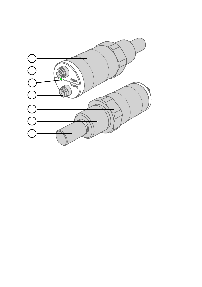
Figure 1 DMT143 Parts – Model with ISO Thread
Transmitter body. Type label is applied here.
1
2 Digital output: non-isolated RS-485
3 Alarm LED
4 Analog output
5 Sealing ring. Must be used with the G1/2” ISO228/1 connection thread.
6 24 mm nut
7 Connection thread: G1/2" ISO228/1
8 DRYCAPâ 180D sensor protected with sintered filter
When the transmitter is delivered, the filter is protected by a yellow transport
protection cap that keeps the sensor dry. The transport protection cap should be
left on the transmitter during storage. Remove the transport protection cap
before installing the transmitter.
12
Page 15
2.3.2 DMT143 with NPT Thread
1
2
3
4
5
6
7
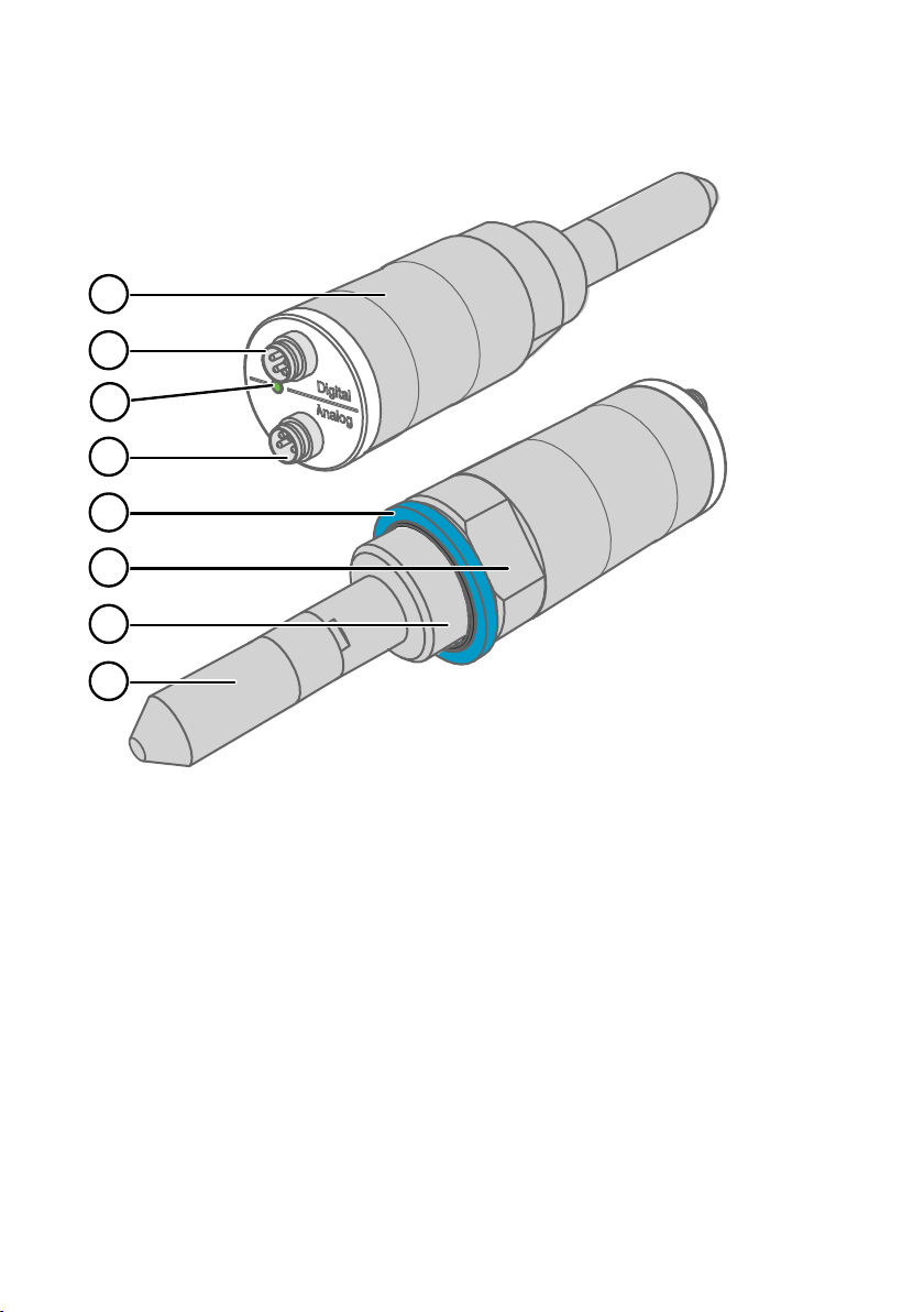
Figure 2 DMT143 Parts – Model with NPT Thread
Chapter 2 – Product Overview
1 Transmitter body. Type label is applied here.
2 Digital output: non-isolated RS-485
3 Alarm LED
4 Analog output
5 30 mm nut
6 Connection thread: NPT 1/2"
7 DRYCAPâ 180D sensor protected with sintered filter
13
Page 16
1
2
3
4
5
6
7
8
DMT143 User Guide M211435EN-J
2.3.3 DMT143L with G1/2” ISO228/1 Thread
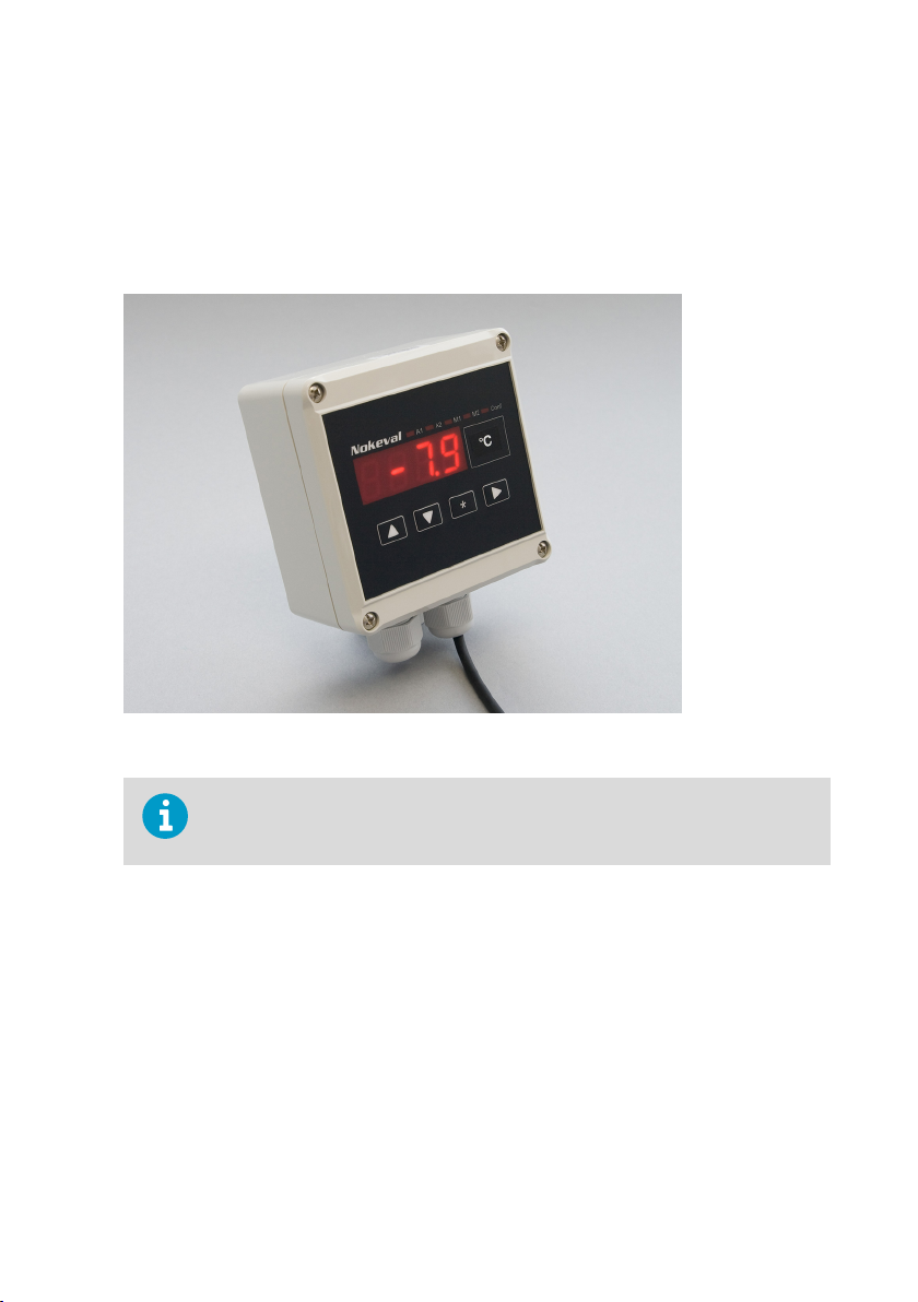
Figure 3 DMT143L Parts
Transmitter body. Type label is applied here.
1
2 Digital output: non-isolated RS-485
3 Alarm LED
4 Analog output
5 Sealing ring. Must be used with the G1/2” ISO228/1 connection thread.
6 24 mm nut
7 Connection thread: G1/2" ISO228/1
8 DRYCAPâ 180M or DRYCAPâ 180S sensor protected with sintered filter
2.4 Loop-powered Display
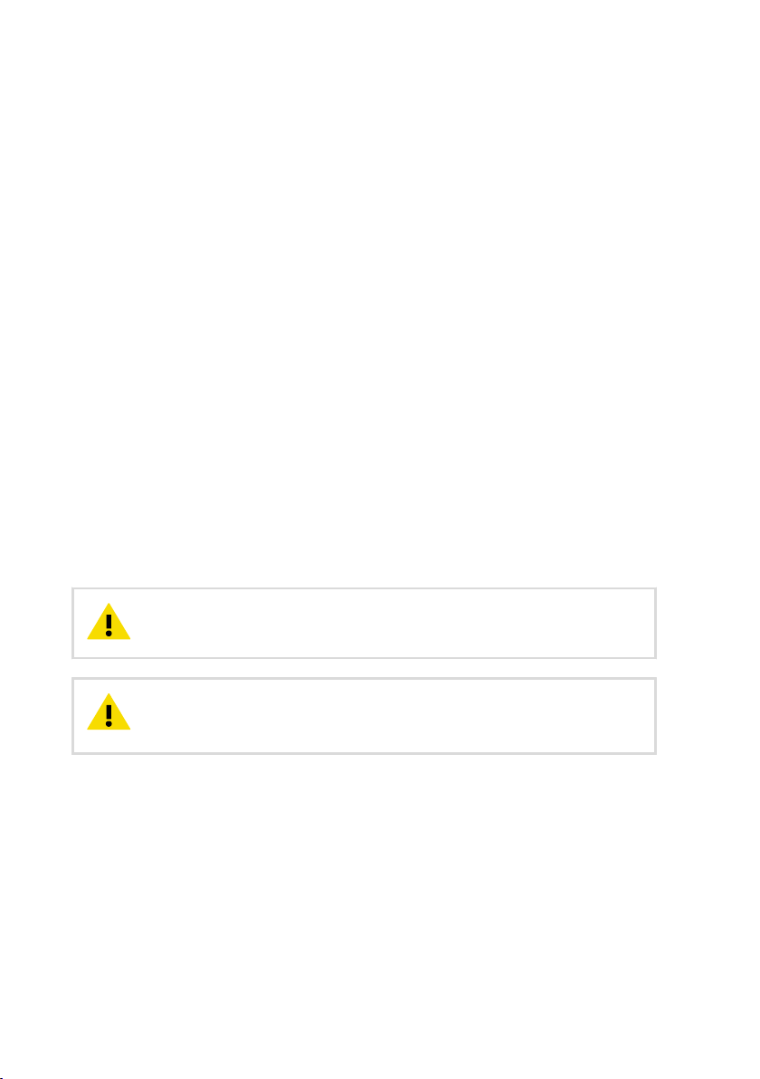
DMT143 can be connected to a loop-powered external LED display. The display provides a
reading of the output parameter. The display is powered by the 4 ... 20 mA current signal, so
there is no need for an external power supply.
14
Page 17
Chapter 2 – Product Overview
Two models are available:
• Nokeval 301
• Nokeval 302 (with alarm relays)
The display is delivered at its default settings. Configure the display functions and scaling
according to the documentation delivered with the display. For a wiring example, see Nokeval
301/302 Display Wiring Diagram (document code M211634EN).
Figure 4 Nokeval 301 Loop-powered Display
The loop resistance of the display must be included in the loop resistance
calculation for the complete current loop. For the loop resistance of the display,
refer to the manufacturer’s documentation.
More Information
‣
Spare Parts and Accessories (page 73)
2.5
Connection Cables
Vaisala supplies shielded cables with M8 female straight threaded connector. Standard cables
are available in four lengths:
• 0.3 m (1.0 ft)
• 3 m (9.8 ft)
• 5 m (16.4 ft)
• 10 m (32.8 ft)
15
Page 18
DMT143 User Guide M211435EN-J
Heavy duty cables are available in two lengths:
• 1.5 m (4.9 ft)
• 3 m (9.8 ft)
Also available are the following cables for service and field check use:
• USB service cable
• MI70 connection cable
More Information
‣
Spare Parts and Accessories (page 73)
2.6 Sampling Accessories
DMT143 is compatible with various sampling accessories.
More Information
‣
Sampling Accessories (page 28)
‣
Spare Parts and Accessories (page 73)
2.7
Safety
This product has been tested for safety. Note the following precautions:
CAUTION!
product or lead to malfunction.
CAUTION!
and is not designed to be opened. Opening the transmitter will void the
warranty.
Do not modify the unit. Improper modification can damage the
The transmitter body does not have user serviceable parts inside,
2.7.1 ESD Protection
Electrostatic Discharge (ESD) can damage electronic circuits. Vaisala products are adequately
protected against ESD for their intended use. However, it is possible to damage the product by
delivering electrostatic discharges when touching, removing, or inserting any objects in the
equipment housing.
To avoid delivering high static voltages to the product:
• Handle ESD-sensitive components on a properly grounded and protected ESD workbench
or by grounding yourself to the equipment chassis with a wrist strap and a resistive
connection cord.
16
Page 19

Chapter 2 – Product Overview
• If you are unable to take either precaution, touch a conductive part of the equipment
chassis with your other hand before touching ESD-sensitive components.
• Hold component boards by the edges and avoid touching component contacts.
2.8 Regulatory Compliances
This product is in conformity with the provisions of the following EU directives:
• EMC-Directive
• RoHS-Directive
Conformity is shown by compliance with the following standards:
• EN 61326-1: Electrical equipment for measurement, control, and laboratory use – EMC
requirements – for use in industrial locations.
• EN 550022: Information technology equipment – Radio disturbance characteristics –
Limits and methods of measurement
17
Page 20

DMT143 User Guide M211435EN-J
3. Functional Description
3.1 DRYCAP Technology
Vaisala DRYCAPâ dew point measurement technology ensures accurate measurement with
excellent long term stability. This results in very low maintenance requirements for the
transmitter. The lasting performance is achieved with microprocessor technology and software
that automatically performs self-diagnostic functions in addition to the normal dew point
measurement. The self-diagnostic procedures that are conducted are called autocalibration,
sensor purge, and sensor warming.
DMT143 and DMT143L use dierent versions of the Vaisala DRYCAPâ sensor:
• DMT143 uses the DRYCAPâ 180D sensor designed for applications such as plastic dryers
and small industrial compressed air dryer (sensor filter length 22.5 mm, probe length 91.6
mm).
• DMT143L can be ordered with two versions of the DRYCAPâ180 sensor: either the 180M
sensor designed for standard dry gas and desiccant dryer applications, or the 180S sensor
designed for more humid applications such as refrigeration dryers. The sensor filter length
of both DMT143L variants is 51 mm, probe length 120 mm.
3.1.1 Autocalibration
The autocalibration feature of the DMT143 transmitter is an automatic procedure which greatly
reduces the possible drift in the dry end of the dew point measurement. It is performed at 1hour intervals, and when the power is switched on. When measuring very dry conditions, the
transmitter performs the autocalibration at shorter intervals. A significant change in dew point
or temperature may also trigger the autocalibration.
During autocalibration the sensor is warmed for a short period (< 1 min) and the sensor
capacitance values are evaluated at the elevated temperature. The possible dry end drift is
then corrected to correspond to the calibrated values. During the autocalibration the
transmitter outputs the Td value prior to the procedure.
Autocalibration is carried out only if several criteria for the measurement environment are
fulfilled. This ensures the reliability of the adjustments, and maintains the excellent long term
stability that the patented technology oers. These criteria include for example a stable
enough moisture level in the measured atmosphere. If the conditions are not fulfilled, the
autocalibration function is postponed until satisfactory conditions are reached.
3.1.2 Sensor Purge
Sensor purge is also an automatic procedure that minimizes the drift at the wet end readings
of the dew point measurement. Sensor purge is performed once a day or when the power is
switched on. The sensor is heated for several minutes which will then evaporate all excess
molecules out of the sensor polymer. This, together with autocalibration, results in a very small
drift of the sensor due to the very linear behaviour of the polymer technology. During the
sensor purge the transmitter outputs the Td value prior to the procedure.
18
Page 21

Chapter 3 – Functional Description
3.1.3 Sensor Warming in High Humidities and Freezing Conditions
DMT143 has a sensor warming feature that improves the sensor’s performance in high
humidities and freezing conditions. Sensor warming does not interrupt the transmitter’s T
value output.
In high humidity, sensor warming prevents the sensor and filter from becoming wet. High
humidity may be present when the dew point temperature rises close to the gas temperature.
Sensor warming is switched on automatically when the humidity in the measured gas
increases to a level where dew can start to form. The advantage of sensor warming is the rapid
response of dew point measurement. A wet sensor and filter would otherwise result in a dew
point equal to ambient temperature (that is, RH = 100 %).
If in spite of sensor warming the sensor gets soaked, it will recover fully back to normal
operation after it dries out.
In freezing conditions, DMT143 uses sensor warming to maintain the sensor temperature above
0 °C.
When measuring in temperatures below 0 °C, the supply voltage must be 24 ... 28
VDC.
More Information
‣
Power Supply Requirements (page 25)
d
3.2
DMT143 Startup Sequence
When the transmitter is powered up, it will perform the sequence (applicable from software
version 1.1.5 onward) shown in Figure 5 (page 20). After a 2-second startup, the transmitter
will measure normally for 40 seconds, after which it will perform the sensor purge and
autocalibration functions. This can take up to 5 minutes, during which time the output is
frozen: it will display the last measured values before the sensor purge began.
The autocalibration function may be postponed if the measurement environment is not
suitable. For example, the environment may be changing rapidly or have too high humidity.
Normal operation and output is typically achieved no later than 6 minutes after startup. The
sensor purge repeats every 24 hours (12 h default interval for the DMT143L variant with
DRYCAPâ 180S sensor if used with purge), and autocalibration every hour. The output will
again be frozen for their duration.
19
Page 22
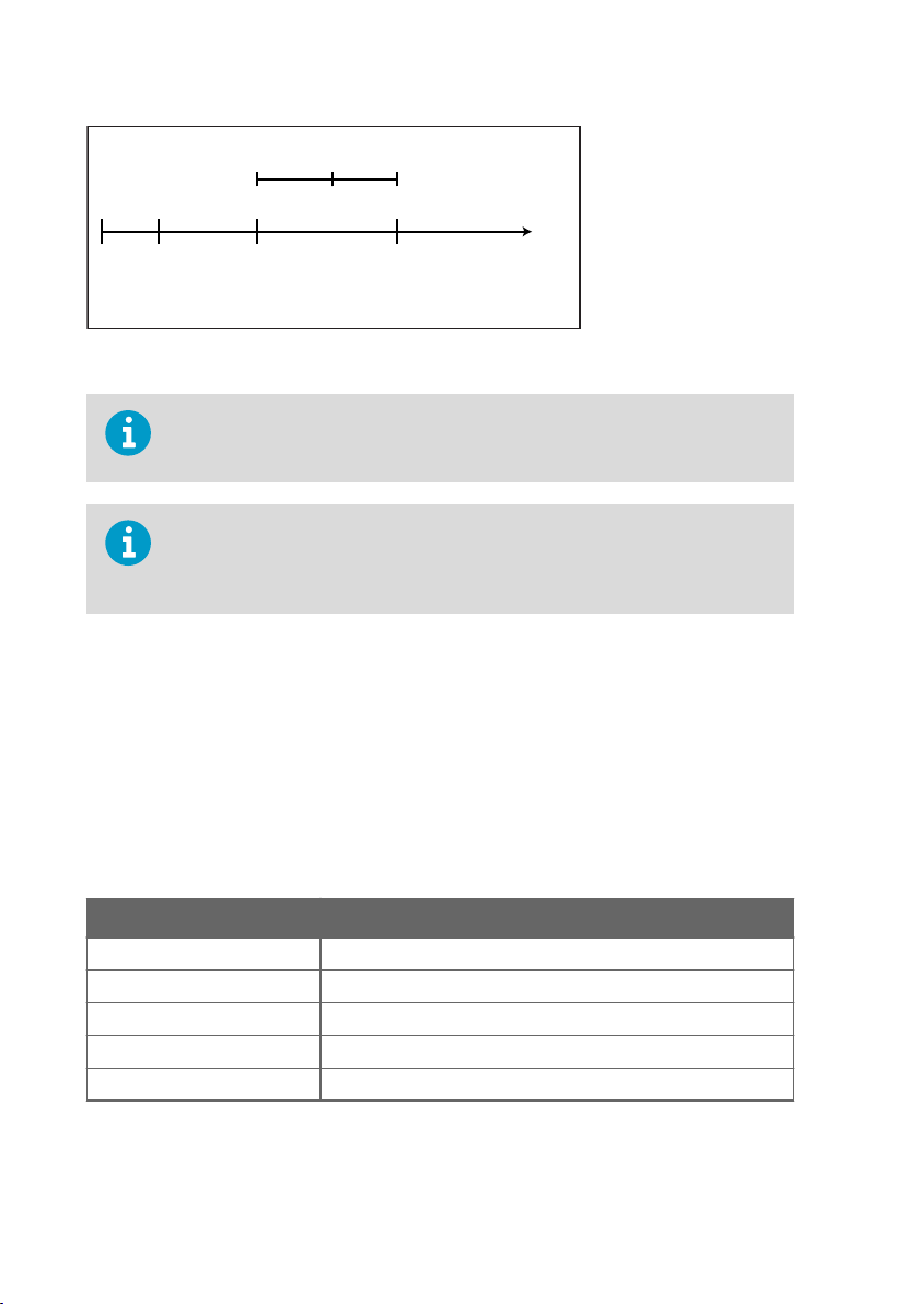
Normal output Normal output
2 s
Output frozen
40 s 3 ... 6 min
Time
Purge*
3 min
Autocal**
<3 min
* Purge will repeat every 24 hours (12-hour default purge interval for
DMT143L variant with DRYCAP® 180S if used with purge)
** Autocal will repeat every 60 minutes (postponed if environment is not suitable)
Startup
DMT143 User Guide M211435EN-J
Figure 5 DMT143 Startup Sequence
The transmitter always performs this sequence when starting up. Keep the
transmitter continuously powered to optimize its measurement performance and
availability.
The DMT143L variant with DRYCAPâ 180S sensor can be used as a replacement
of the DMT242 transmitter and ordered without the purge functionality. If you use
purge with the DMT143L variant with DRYCAPâ 180S, the default purge interval is
12 hours.
3.3 Alarm LED
The alarm LED at the back of the transmitter provides a visual indication of the transmitter's
status. The alarm LED functionality is preset at the factory according to order form. You can
configure it as follows:
• You can use Vaisala Insight software or the ALARM command on the serial line to change
the alarm limit, enable/disable the dew point alarm, or turn on/o the LED completely.
• You can change the alarm limit using the DM70 handheld dew point meter.
Table 4 Alarm LED States
LED Color Meaning
Not lit Power o or LED functionality disabled.
Green Power on, normal measurement.
Green and blinking Purge or autocalibration in progress, measurement frozen.
Red Dew point above limit.
Red and blinking Transmitter error.
20
Page 23

More Information
‣
Vaisala Insight Software (page 36)
‣
Operation with DM70 Handheld Dew Point Meter (page 38)
‣
Configure the Alarm LED (page 60)
Chapter 3 – Functional Description
21
Page 24

DMT143 User Guide M211435EN-J
4. Installation
4.1 Configuring Transmitter Before Installation
You may wish to configure your transmitter before physically installing it. For easy access to
configuration options, use either Vaisala Insight PC software with the USB service cable
(Vaisala order code 219690), or connect to the serial line using the USB service cable and a
terminal program on a PC.
Some configuration settings can also be changed using the DM70 handheld meter.
Examples of configurable settings for analog output:
1. Analog output parameter and scaling.
2. Analog output error level.
Examples of configurable settings for RS-485 output:
1. By default, DMT143 transmitters are configured for single transmitter operation. Serial
operation mode is STOP and address is 0.
To configure transmitters for operation on a common line, you must give each transmitter
a unique address (range 0 ... 255) and set their serial operation mode to POLL.
2. The default serial line settings may not be right for your RS-485 line.
3. You may need to change the transmitter’s serial output format to suit your needs.
More Information
‣
Vaisala Insight Software (page 36)
‣
Operation with DM70 Handheld Dew Point Meter (page 38)
‣
Connecting to the Serial Interface (page 41)
4.2
Selecting the Location
It is important that the point of installation represents well the gas to be measured.
Temperature changes do not aect the dew point measurement, but pressure changes will
have an eect on the measurement. All leaks in the system must be eliminated to avoid
ambient humidity aecting the measurement.
Direct installation to the measured gas is the recommended installation method if the
temperature of the gas is suitable for DMT143 and no additional filtering is needed due to very
dusty or oily gas. Oil as such is not harmful for the DRYCAPâ sensor, but response time may
be slower if there are oil particles in the system, or if oil is collected to the filter over a longer
period of time. The maximum measurement pressure is 50 bara / 725 psia (absolute pressure)
for direct measurement.
22
Page 25
Chapter 4 – Installation
If the gas temperature is higher than the specified maximum operating temperature of the
transmitter, gas sampling and cooling it to ambient temperature (for example, 20 °C / 68 °F) is
recommended. Note that the dew point temperature must be clearly lower than the ambient
temperature to avoid condensation in the sampling line. Sampling from the process is easy by
using Vaisala sampling cell options.
The DMT143 is light in weight, which means that it can be installed in a sample pipeline in the
sampling cells without the need of any additional mechanical support. You can use a standard
G1/2" T-shaped pipe fitting (not available from Vaisala) when installing DMT143 into a pipeline.
More Information
‣
Sampling Accessories (page 28)
4.3 Installing the Transmitter
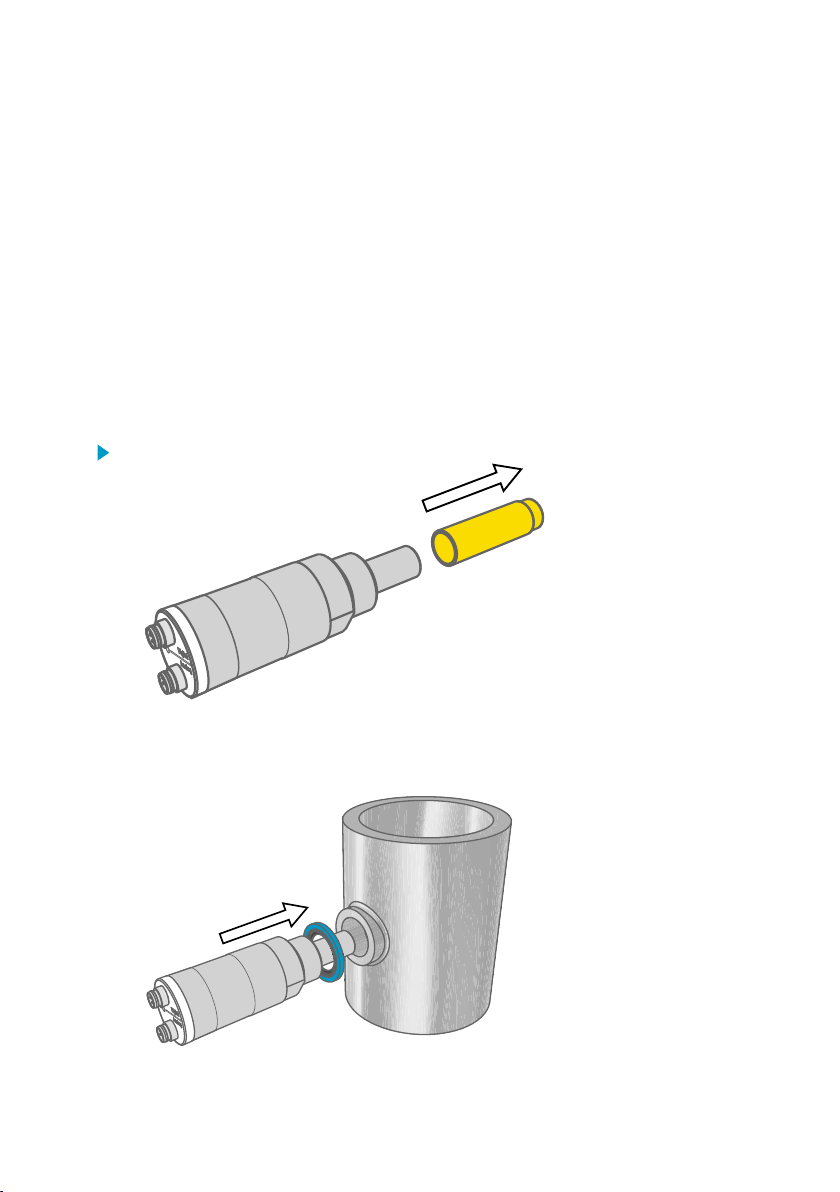
1. Remove the yellow transport protection cap from the transmitter.
2. The DMT143 models with a parallel thread (G1/2" ISO 228/1) require a sealing ring for a
tight connection. Use the sealing ring that is provided with the transmitter. Make sure the
threads on the mounting point match your transmitter.
For the model with NPT thread, do not use a sealing ring.
23
Page 26
DMT143 User Guide M211435EN-J
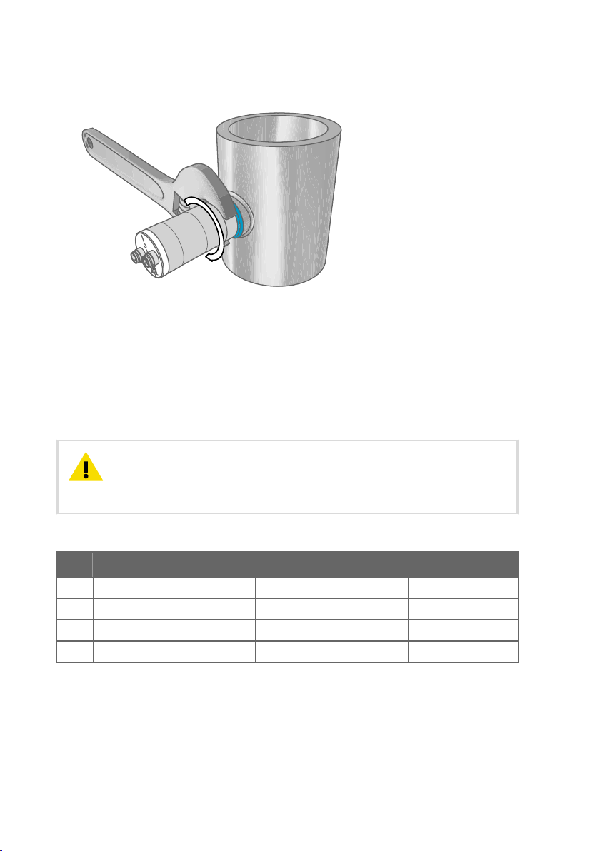
3. Tighten the connection by turning with a wrench (max. 50 Nm). Wrench size is 24 mm for
ISO threaded transmitters, 30 mm for NPT threaded model.
4. Connect the signal and power cable to the DMT143.
More Information
‣
Wiring (page 24)
‣
Power Supply Requirements (page 25)
4.4
Wiring
CAUTION!
one of them, but do not connect more than one supply voltage in permanent
installations. Temporary simultaneous use with the USB service cable or DM70
handheld dew point meter (which also provides power) is fine.
Table 5 Connector Pinouts
Pin Analog connector Digital connector Wire color
1 VDC supply+ VDC supply+ Brown
2 Ch- RS-485 D0- White
3 GND GND Blue
4 Ch+ RS-485 D1+ Black
24
The power supply lines are internally connected. You can use either
Page 27
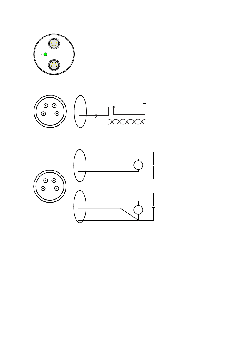
Digital
Analog
Figure 6 DMT143 Digital and Analog Connectors
2
4
1 3
12 ... 28 V D C
RS -4 85 +
RS -4 85 -
GN D
1
2
3
4
+
-
+
-
1
3
4
2
mA
+
-
1
3
4
2
V
18 . .. 2 8 VDC
12 . .. 2 8 VDC
2
4
1 3
+
-
+
-
Figure 7 Wiring the Digital Connector
Chapter 4 – Installation
Figure 8 Wiring the Analog Connector
4.4.1 Power Supply Requirements
The minimum supply voltage required by the DMT143 transmitter depends on the analog
output type that is used:
• For voltage output: 12 ... 28 VDC.
• For current output: 18 ... 28 VDC. The maximum load is 500 Ω.
The power supply should maintain the voltage for all load conditions.
If measuring in pressures above 20 bara (290 psia) or temperatures below 0 °C, the supply
voltage must be 24 ... 28 VDC.
25
Page 28
250 mA
Duration 50 s
Duration 5 s
0 mA
250 mA
0 mA
DMT143 User Guide M211435EN-J
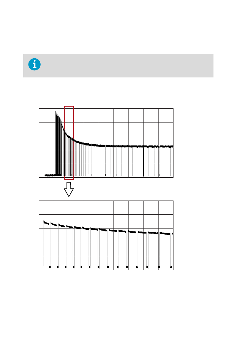
Current consumption during normal operation is <10 mA. The consumption increases during
the sensor self-diagnostics (autocalibration and sensor purge). Typical
current consumption
is 220 mA pulsed current.
The DMT143 can be powered by the MI70 indicator or the USB service cable. You
can plug in the MI7
0 indicator or the USB service cable to the digital port while
the transmitter is powered from the analog port.
The following figur
e shows a typical duty cycle during sensor purge at room temperature with
24 VDC supply voltage. Sensor purge current varies with supply voltage and operating
temperature. The peak value is the highest in the lowest temperature.
Figure 9 Example of Current Consumption During Purge
26
Page 29
250 mA
Duration 16 s
Duration 200 ms
0 mA
250 mA
0 mA
Chapter 4 – Installation
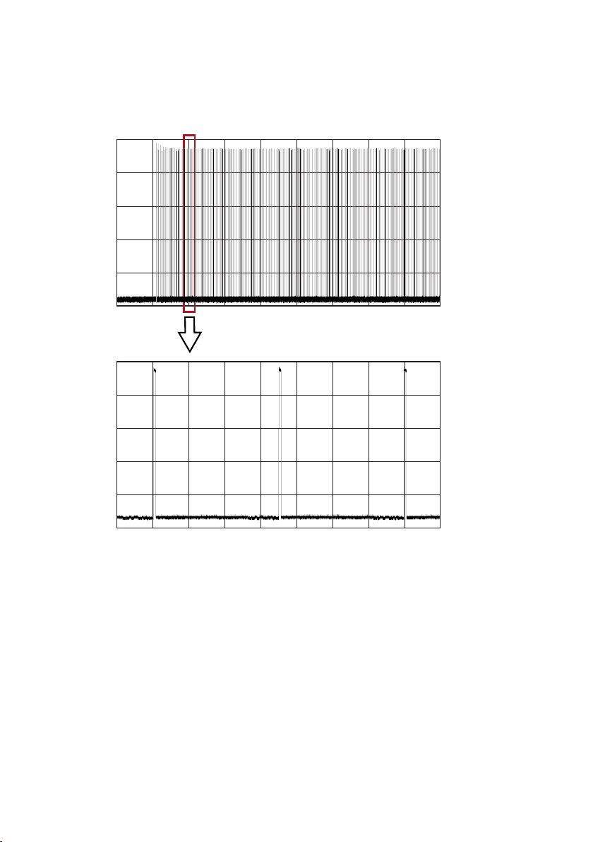
The following figure shows a typical duty cycle during autocalibration at room temperature
with 24 VDC supply voltage. Also the autocalibration current varies with supply voltage and
operating temperature.
Figure 10 Example of Current Consumption During Autocalibration
4.5
Sampling from a Process
Sampling is needed when direct measurement of the air or gas is not possible or desirable.
This may be related to, for example, a high process temperature, protecting the sensor from
water spikes, the need to easily detach the instrument from a pressurized process without
running the whole process down, or wanting to make the measurement at a more convenient
location.
It is important to keep in mind that changing the pressure of a gas changes the dew point
temperature of the gas. If the sensor is at a dierent pressure than the process itself, there may
be an error of several tens of degrees in the dew point measurement.
27
Page 30

DMT143 User Guide M211435EN-J
Make sure there is sucient flow of gas to the sensor (for example, 1 l/min) to give a
representative sample.
To simulate the eect of pressure change to dew point, you can use the Vaisala Humidity
Calculator at: www.vaisala.com/humiditycalculator.
4.6 Sampling Accessories
4.6.1 DMT242SC Sampling Cell
The DMT242SC is a basic sampling cell with only the main sampling cell body. The inlet and
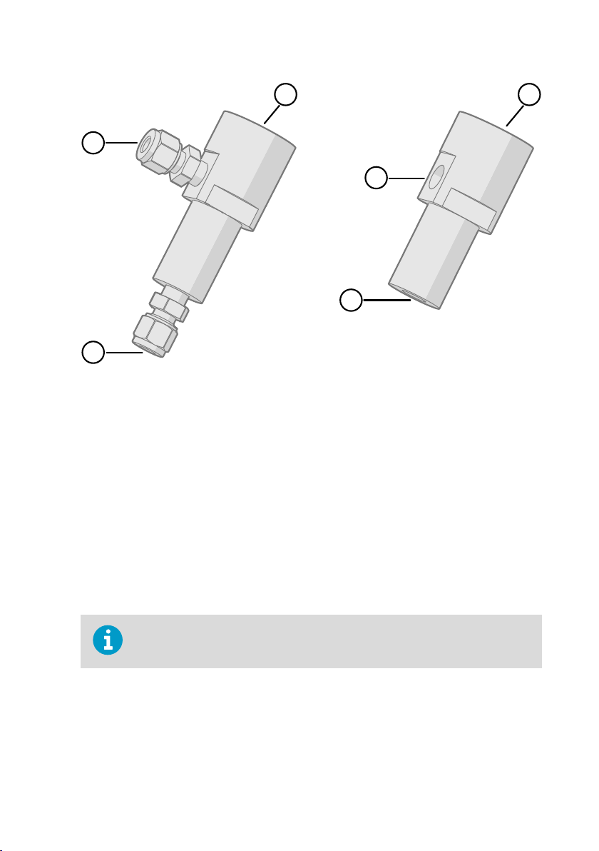
outlet are female threaded sample connectors (inlet G3/8", outlet G1/4" ISO).
The DMT242SC is suitable for users requiring only a sampling cell to fit the transmitter into and
doing further assembly (piping into inlet and outlet, valves, possible flow meter) by
themselves.
4.6.2 DMT242SC2 Sampling Cell with Swagelok Connectors
The DMT242SC2 is similar to DMT242SC, but connections are made easy. The sampling cell
includes welded swagelok connectors at both the inlet and outlet that fit directly to 1/4"
tubing.
To fit 6 mm tubing to the connectors, an adapter such as Swagelokâ Reducer SS-6M0-R-4
(not supplied by Vaisala) can be used.
DMT242SC2 is the suitable choice in, for example, plastics drying systems, where the
measurement is made by tapping o the dryer system and bringing a small air stream to the
sensor.
The Swagelok connectors of DMT242SC2 easily connect to a cooling coil or tubing providing
the essential function of cooling the dry air to ambient temperature before it reaches the
sensor.
28
Page 31
3
2
1
1
2
4
Figure 11 Sampling Cells DMT242SC2 (left) and DMT242SC (right)
1 Male pipe welded connector Swagelok 1/4"
2 G1/2"
3 G1/4"
4 G3/8"
Chapter 4 – Installation
4.6.3 DSC74 Sampling Cell with Quick Connector and Leak Screw
The DSC74 has been designed especially for compressed air lines. The sampling cell contains
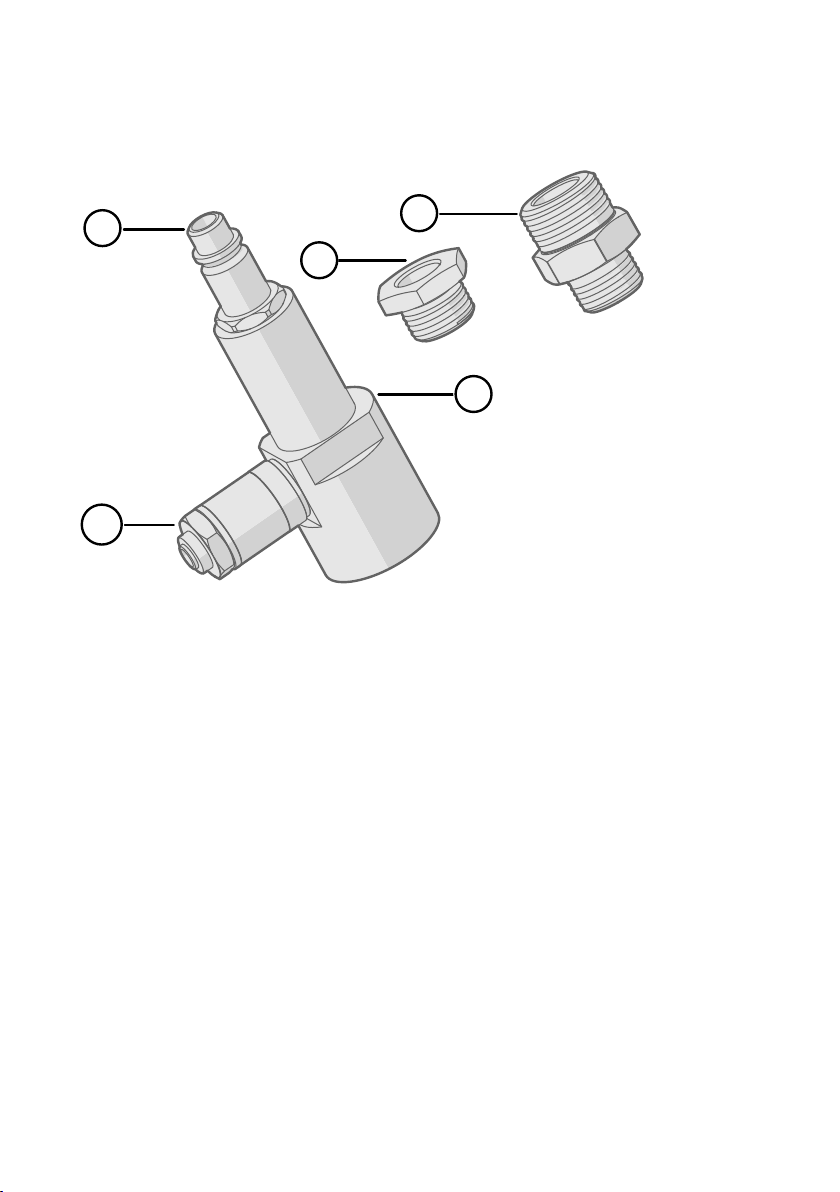
an adjustable leak screw that allows keeping up the pipeline pressure at the sensor. The leak
screw is opened and closed with a screwdriver. The leak screw should be 1/2 turn open. This
can be verified by first closing the leak screw, then turning 1/2 turn to open it. Then the air
coming out will make a barely audible little hiss and it can be lightly felt when putting a hand
in front of the air stream.
Do not open the leak screw more than 1/2 turn to avoid reducing the pressure in
the sampling cell.
The DSC74 comes with a quick connector that fits to industry standard compressed air line
connectors (suitable for type D, Quick08, NIP08). This allows for easy installation and
detachment of the dew point transmitter without having to shut down the process. Alternative
ways to connect are through the two dierent thread adapters (G3/8" to G1/2" and G3/8" to
G1/4" ISO) that are supplied with each DSC74 unit.
29
Page 32
4
3
1
2
5
DMT143 User Guide M211435EN-J
When using the DSC74, seal the threads of the quick connector or thread adapter carefully
with PTFE thread seal tape. Tighten with an open-end wrench.
Figure 12 DSC74 Sampling Cell with Accessories
1 Thread adapter type G3/8" - G1/2"
2 Thread adapter type G3/8" - G1/4"
3 Quick connector
4 Leak screw
5 Sampling cell body (DMT242SC)
4.6.4 DSC74B Two-Pressure Sampling Cell
The DSC74B and DSC74C sampling cells are enhanced versions of the DSC74. The body is
designed in a way that it is possible to measure at both system pressure and atmospheric
pressure.
The DSC74B limits the flow rate with a fixed leak screw. The flow is optimized for pressures 3 ...
10 barg. The fixed leak screw eliminates the risk of opening the leak screw fully by accident
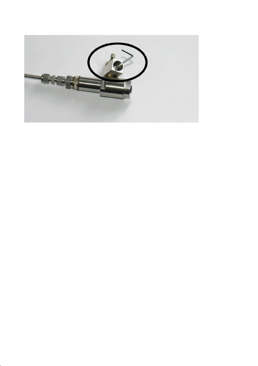
and this way emptying a gas vessel. The maximum flow can be increased, if needed, by
removing the leak screw and adjusting the flow manually with the valve. Harmful gases can be
recovered by connecting a collection system at the outlet (not available from Vaisala).
In the basic operation of the DSC74B, the gas flows to the sensor from the front and the outlet
is on the side. To have the measurement done at atmospheric pressure, the inlet and outlet are
reversed. Then the reducing parts supplied (G3/8" - G1/2" or G3/8" - G1/4") on the outlet side
help to protect the sensor from ambient humidity coming in.
30
Page 33
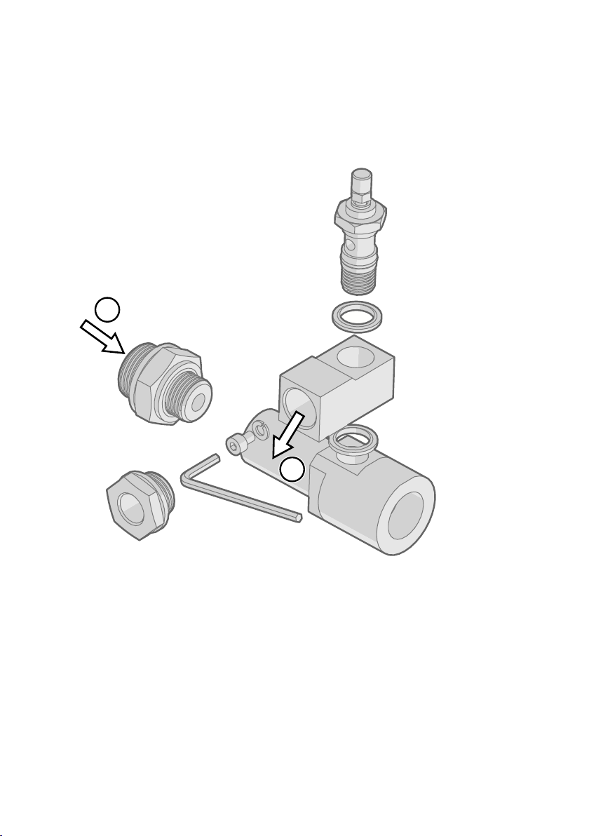
DSC74B parts are:
1
2
• Sampling cell, thread G3/8"
• Connection part with a needle valve and an integrated leak screw
• Reducing Nipple (thread adapter), G3/8" - G1/2"
• Reducing Adapter (thread adapter), G3/8" - G1/4"
Chapter 4 – Installation
Figure 13 DSC74B
Gas goes in
1
2 Gas comes out
31
Page 34
DMT143 User Guide M211435EN-J
Figure 14 Removing the Leak Screw
4.6.4.1 DSC74C Two-Pressure Sampling Cell with Coil
The DSC74C with an outlet coil is designed for the most critical measurements at atmospheric
pressure. In the DSC74C, the coil is connected to the sampling cell outlet to protect the sensor
from ambient humidity disturbing the measurement. The coil can also be used as a cooling coil
for sampling from high temperature processes.
DSC74C parts are:
• Sampling cell, thread G3/8"
• Connection part with a needle valve and an integrated leak screw
• Reducing Nipple (thread adapter), G3/8" - G1/2"
• Reducing Adapter (thread adapter), G3/8" - G1/4"
• Diusion coil (for measurements in atmospheric pressure)
32
Page 35
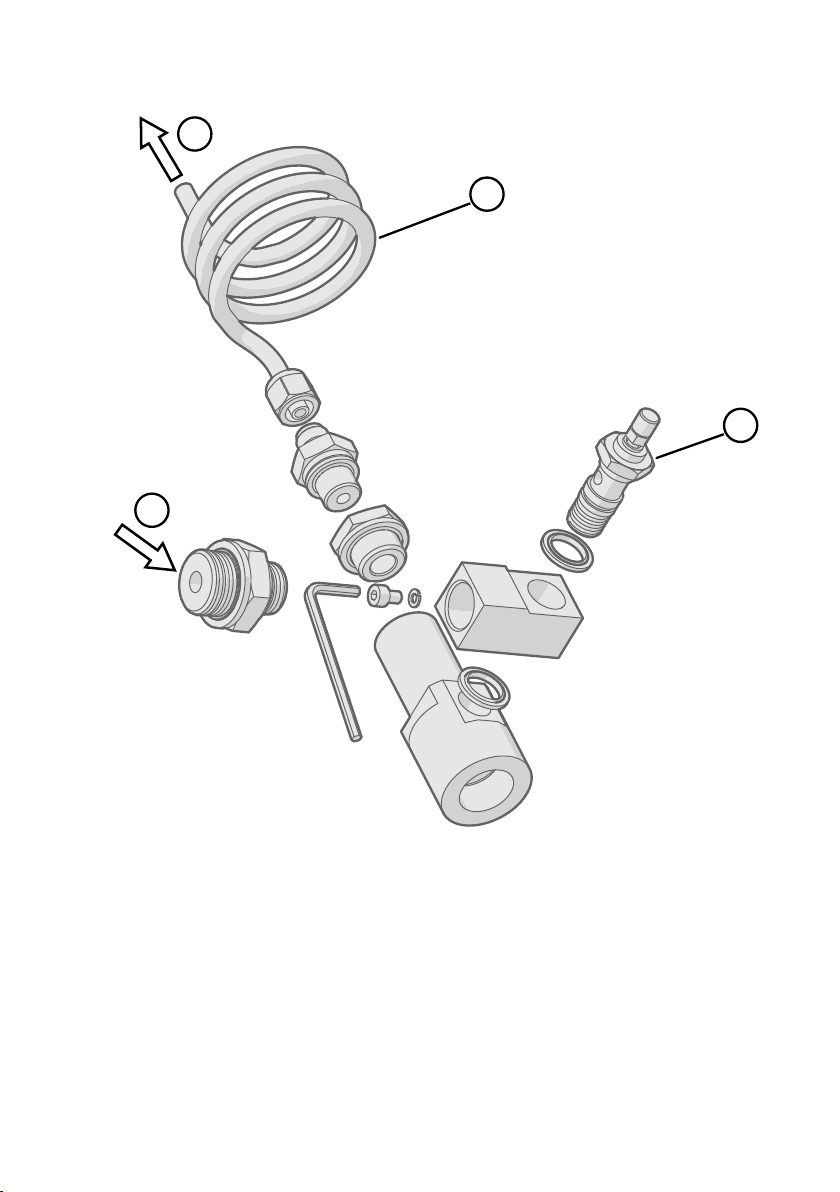
3
4
1
2
Chapter 4 – Installation
Figure 15 Default Assembly of DSC74C
Gas goes in. The coil can also be used here.
1
2 Gas comes out
3 Coil
4 Valve
33
Page 36
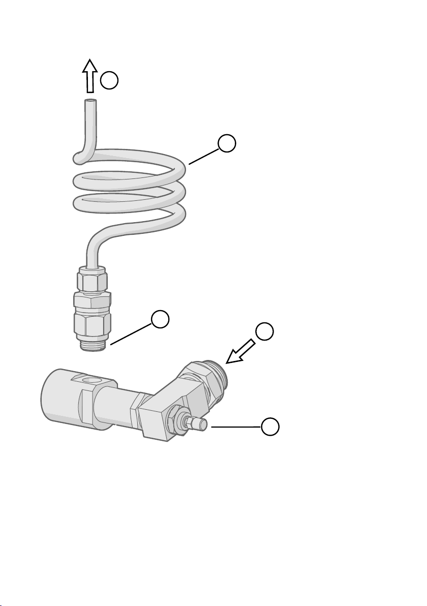
1
2
3
4
5
DMT143 User Guide M211435EN-J
Figure 16 Alternative Assembly of DSC74C (for Tight Spaces)
Gas comes out
1
2 Coil
3 Thread, max. size 7 mm
4 Gas goes in
5 Valve
The thread size cannot exceed 7 mm. Use the provided adapter to avoid damage to the
transmitter.
34
Page 37
1
2
3
4
Chapter 4 – Installation
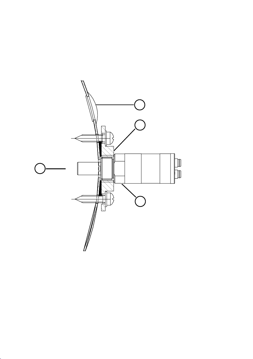
4.6.4.2 DM240FA Duct Installation Flange
DMT143 models with a G1/2” ISO228/1 connection thread can be installed directly in the
process wall through a DM240FA duct installation flange. When the transmitter is installed
directly on the process wall or pipe, note that a closing valve may be needed on both sides of
the installed transmitter so that the sensor head can be removed from the process for
calibration or maintenance.
Figure 17 DM240FA with DMT143
Measured gas
1
2 Recommended additional hole (plugged) for Td field check reference measurement probe
(for example, Vaisala DM70)
3 DM240FA flange (thread G1/2” ISO228/1)
4 DMT143 transmitter
35
Page 38

DMT143 User Guide M211435EN-J
5. Operation
5.1 Transmitter Start-up
When the transmitter is connected to power supply, there is a delay of 2 seconds as the
transmitter starts up. After the start-up is complete, the measurement data is available from
the analog output and serial line.
If serial line output is used, note that the transmitter will behave according to the configured
serial mode:
• In STOP mode, the transmitter outputs the transmitter model and software version. This is
the default mode.
• In RUN mode a measurement output starts immediately.
• In POLL mode the transmitter does not output anything after power-up.
• In MODBUS mode, the device does not output anything after power-up.
More Information
‣
DMT143 Startup Sequence (page 19)
‣
Power Supply Requirements (page 25)
‣
Set Serial Line Operating Mode (page 57)
5.2
Vaisala Insight Software
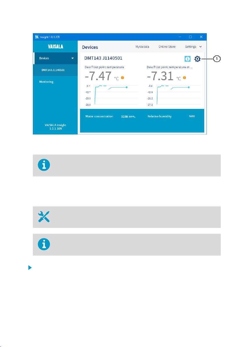
You can use Vaisala Insight PC software to check and configure DMT143 transmitters
intuitively, without typing any serial commands. The software guides you when changing the
settings on the transmitter. The transmitter can be connected to Insight software using a
Vaisala USB cable for computer connection (order code 219690).
With the Insight software, you can:
• See device information and status.
• See real-time measurement.
• Configure serial communication settings, filtering factor, alarm LED, and analog output
parameters and scaling.
36
Page 39
Chapter 5 – Operation
1 DMT143 settings are available through the settings wheel in the Insight Devices view.
DMT143 transmitters support Insight from transmitter software version 1.4.4
onwards.
Download Insight software at www.vaisala.com/insight.
5.2.1 Connecting to Insight Software
• Computer with Vaisala Insight software installed
• USB connection cable (order code 219690)
Before connecting the transmitter to a PC, disconnect the cables from both the
analog and digital ports of the transmitter.
1. Open the Insight software.
2. Connect the USB cable to a free USB port on the PC.
3. Connect the USB cable to the digital port of the transmitter.
4. Wait for Insight software to detect the transmitter.
If the transmitter is not detected, disconnect and reconnect the Vaisala USB cable to the
digital port connector of the transmitter.
37
Page 40
DMT143 User Guide M211435EN-J
5.3 Operation with DM70 Handheld Dew Point Meter
You can connect the DMT143 to the MI70 indicator (the handheld measurement display
included in the DM70 package) using the MI70 connection cable (order code 219980SP). This
allows you to view and use the measurement data with the MI70 indicator. You can, for
example, perform a field check of the measurement accuracy.
When connecting or disconnecting the MI70 indicator, always make sure the MI70 indicator is
powered o. Connecting or disconnecting the MI70 when it is powered on may cause incorrect
values to be displayed.
If you have altered the serial port settings of the DMT143, always make sure you switch o the
other power supply (disconnect the “Analog” cable if in use) before powering up the MI70
indicator.
When the transmitter's power supply is disconnected, it will carry out the startup
sequence when powered on again.
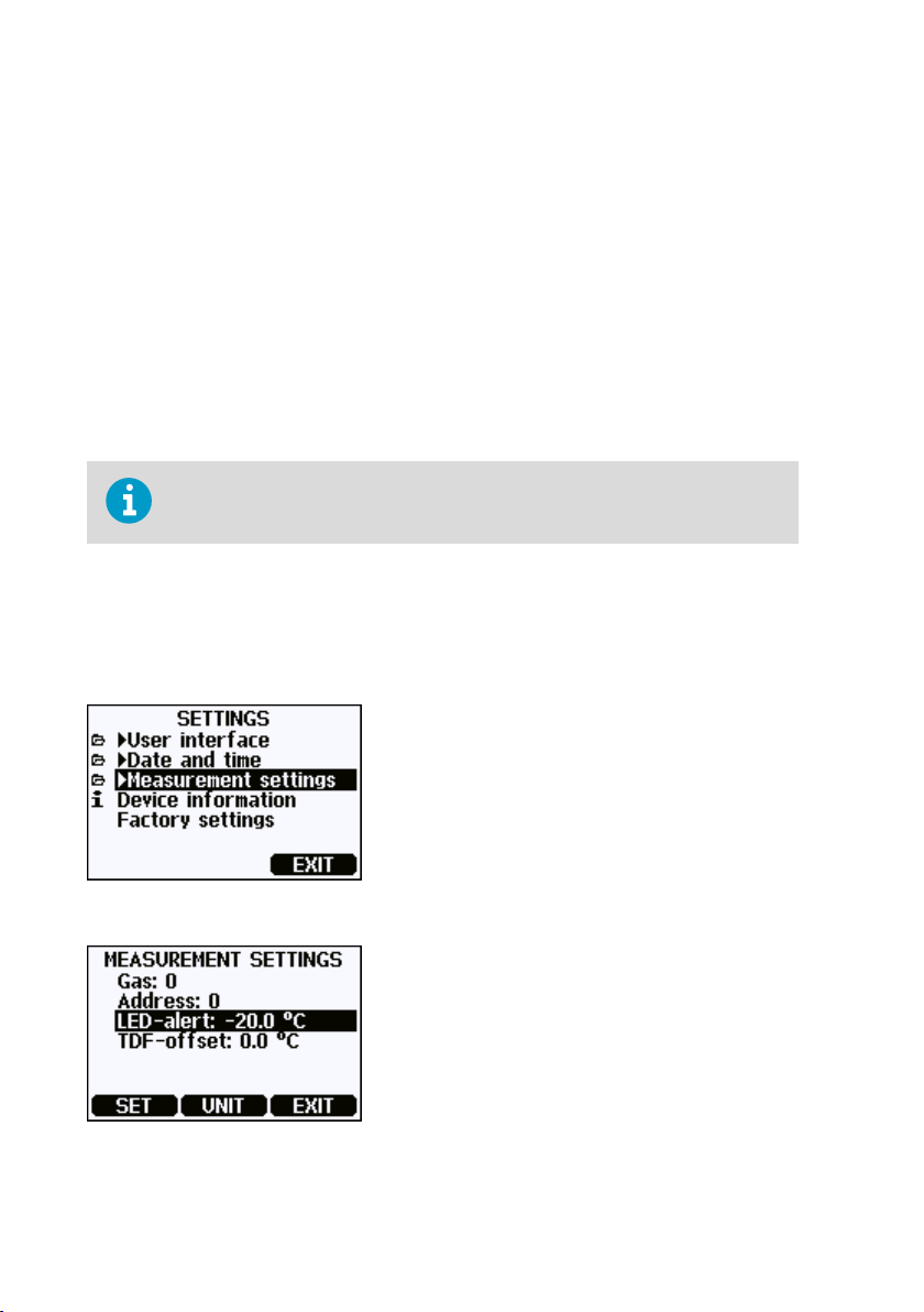
You can adjust the following DMT143 settings in the MI70
• Transmitter address in POLL mode.
• Alarm LED dew point limit (not shown if dew point alarm is disabled or LED is completely
turned o).
• Oset correction for dew point measurement. The maximum oset you can set is ±5 °C.
Figure 18 Settings Menu
Figure 19 Measurement Settings Menu
Measurement Settings menu:
38
Page 41

You can also return the DMT143 to its factory configuration by using the Factory
settings option in the Settings menu. This option is equivalent to using the
FRESTORE command on the serial line. Note that also the MI70 indicator will
revert to its factory configuration when using the Factory settings option on the
MI70.
More Information
‣
DMT143 Startup Sequence (page 19)
‣
Field Check Using DM70 Handheld Dew Point Meter (page 63)
Chapter 5 – Operation
39
Page 42

DMT143 User Guide M211435EN-J
6. Modbus Communication
Transmitters ordered with the Modbus configuration option are accessed using the Modbus
serial communication protocol. The supported Modbus variant is Modbus RTU (Serial Modbus)
over RS-485 interface.
The supported Modbus functions and registers are described in Modbus Reference
(page 75).
The following table lists the default Modbus serial settings of devices ordered with the Modbus
configuration option.
Table 6 Default Modbus Serial Communication Settings
Description Default Value
Serial bit rate 19200
Parity N
Number of data bits 8
Number of stop bits 2
Modbus device address 240
Serial delay 0
Communication mode Modbus RTU
Use Vaisala Insight software to change the Modbus serial communication settings if needed.
More Information
‣
Vaisala Insight Software (page 36)
40
Page 43
Chapter 7 – Serial Communication
7. Serial Communication
7.1 Connecting to the Serial Interface
To interface with DMT143 using Vaisala Industrial Protocol with a terminal application, the
transmitter can be connected to a PC using the RS-485 line on the Digital port. It is
recommended that you use the USB service cable (Vaisala order code 219690) for the
connection, since the cable also provides the operating power from the USB port. If you have
not used the USB service cable before, install first the driver that came with the cable.
7.2 Terminal Application Settings
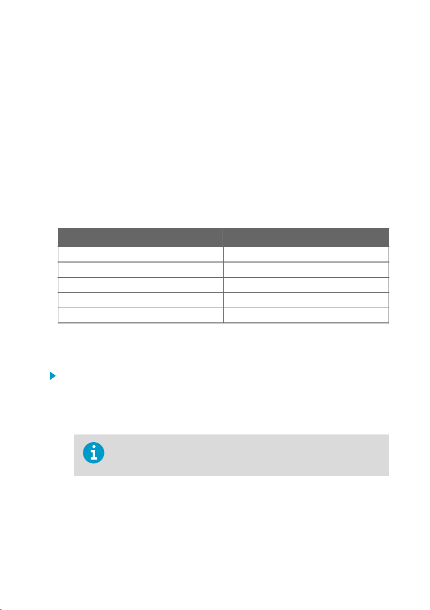
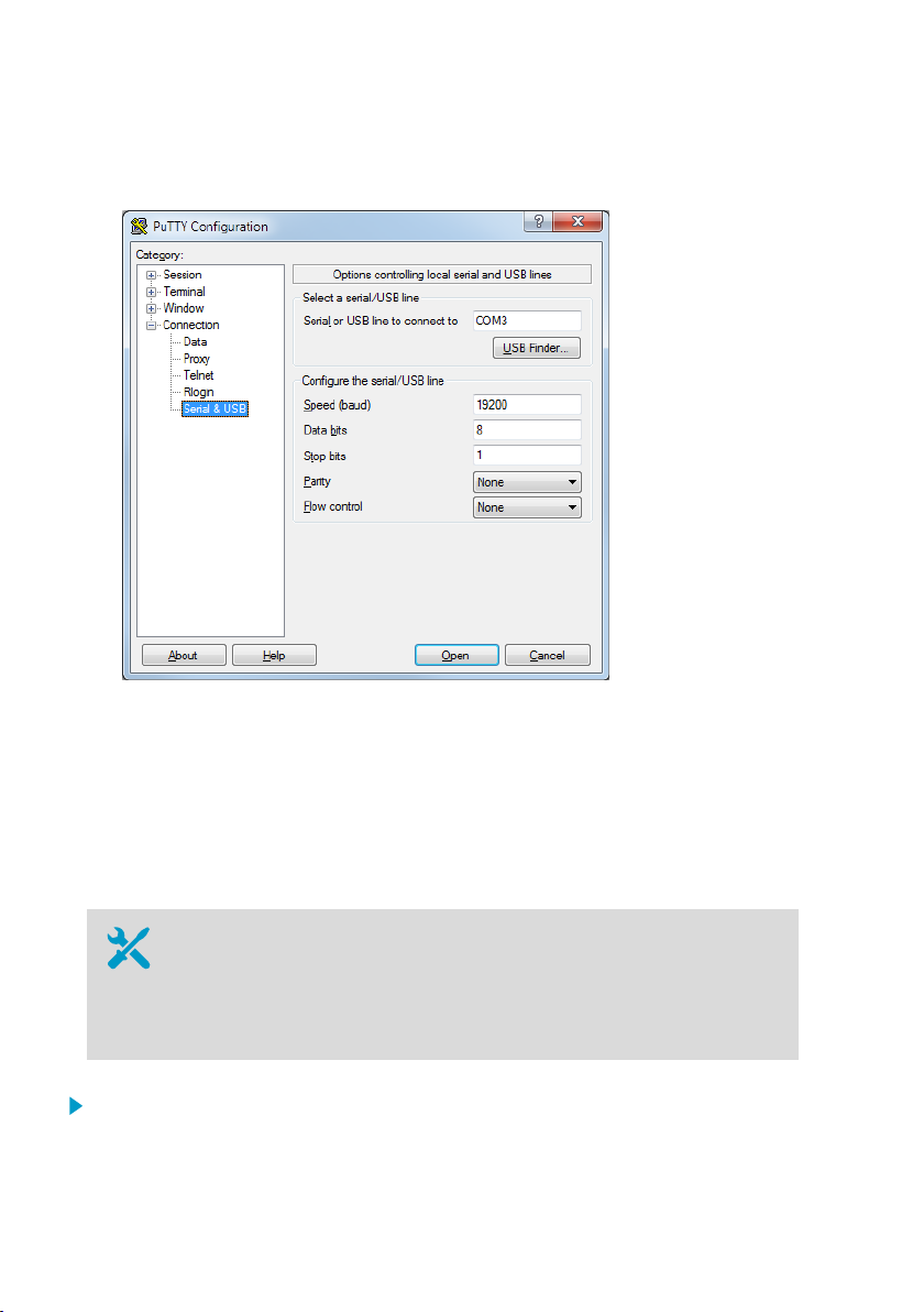
Table 7 Default Serial Interface Settings
Property Description / Value
Baud rate 19200
Parity None
Data bits 8
Stop bits 1
Flow control None
The following steps describe how to connect to the DMT143 using the PuTTY terminal
application for Windows (available for download at www.vaisala.com/software) and a USB
serial interface cable:
1. Connect the USB serial interface cable between your PC and the RS-485 port of the
DMT143 (Digital port).
2. Start the PuTTY application.
3. Select the Serial settings category, and check that the correct COM port is selected in the
Serial line to connect to field.
You can check which port the USB cable is using with the Vaisala USB
Instrument Finder program that has been installed in the Windows Start
menu.
4. Check that the other serial settings are correct for your connection, and change if
necessary. Flow control should be set to None unless you have a reason to change it.
5. Click the Open button to open the connection window and start using the serial line. If
PuTTY is unable to open the serial port you selected, it will show you an error message
instead. If this happens, restart PuTTY and check the settings.
41
Page 44
DMT143 User Guide M211435EN-J
6. You may need to adjust the Local echo setting in the Terminal category to see what you
are typing on the serial line. To access the configuration screen while a session is running,
click the right mouse button over the session window, and select Change Settings... from
the pop-up menu.
7.3 Accessing Serial Interface in Devices with Modbus Output
Follow the steps below to connect to the serial line with a transmitter with Modbus output. You
can also use the procedure to retrieve the communication settings of your device, if you do not
know them. You must use the Vaisala USB cable (Vaisala order code 219690) for the
connection.
• Computer with
• Windows operating system
• Terminal application
• Free USB port
• Driver for Vaisala USB cable installed
• Vaisala USB cable for computer connection (219690)
1. Connect the USB cable to the PC and install the driver, if necessary. Do not connect the
cable to the transmitter yet.
42
Page 45

Chapter 7 – Serial Communication
2. Open the terminal program and open a connection to the corresponding COM port using
the default settings 19200, 8, N, 1, no flow control.
3. Keep the Enter key pressed down and connect the other end of the USB cable to the
transmitter. This will cause the transmitter to start in serial mode, using the default serial
settings.
You can now use the transmitter with the terminal program.
To prevent Modbus mode from being restored on the next power-up, select a dierent serial
mode with the smode command.
7.4 List of Serial Commands
All commands can be issued either in uppercase or lowercase. In the command examples, the
keyboard input by the user is in bold type.
The notation <cr> refers to pressing the carriage return (Enter) key on your computer
keyboard. Enter a <cr> to clear the command buer before starting to enter commands.
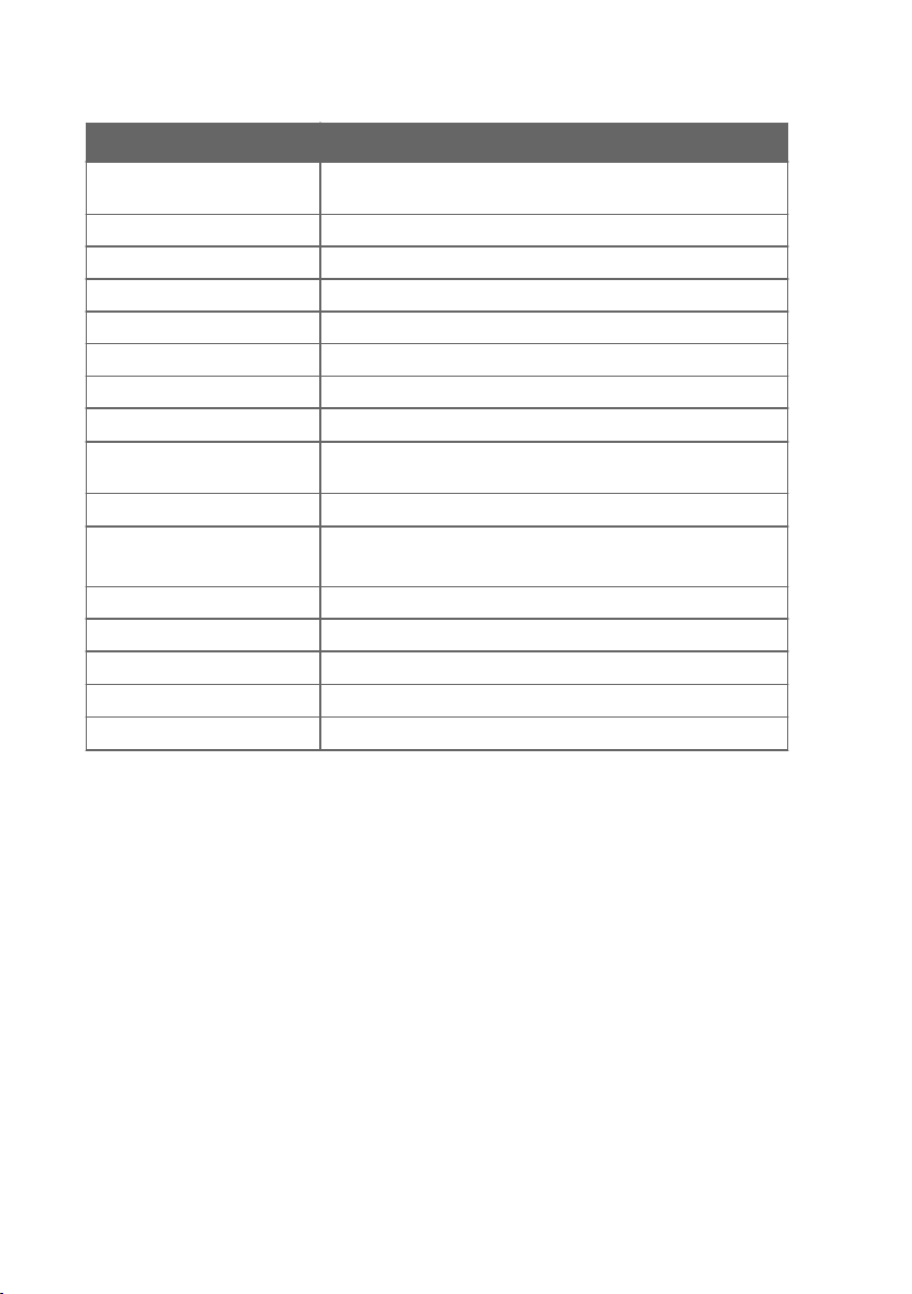
Table 8 List of Serial Commands
Command Description
<ESC>
?
??
ADDR [0 ... 255] Show or set transmitter address
AERR
ALARM
AMODE
AOUT [ON/OFF] Enable or disable analog output
AOVER [ON/OFF]
ASEL
ATEST
CLOSE
ERRS
FILT [0 ... 1] Set output filtering level
FORM [modifier string]
FRESTORE
HELP
Stop the continuous outputting of RUN mode or R command
Show device information
Show device information (overrides poll mode)
Set analog output error level
Set dew point level for LED alarm
Show analog output mode
Allow analog outputs to exceed their range 10 %
Set analog output parameter and scaling
Test analog output
Close the temporary connection and return the device to POLL
mode
Display the currently active errors
Set output format
Restore factory settings
Show list of currently available serial commands
43
Page 46
DMT143 User Guide M211435EN-J
Command Description
INTV [0 ... 255
S/MIN/H]
L
LI
OPEN [0 ... 255]
PRES [0.001 ... 50]
R
RESET
SDELAY [0 ... 255] Set response sending delay
SEND [0 ... 255] Output readings once (specify address for transmitters in POLL
SERI [baud p d s] Show or set the serial interface settings
SMODE [mode]
SNUM
SYSTEM
UNIT [m/n] Select metric or non-metric units
VERS
XPRES [0.001 ... 50] Set temporary pressure compensation value
Set the continuous output interval (for RUN mode and R
command)
Show user adjustment values
Set user adjustment values
Open a line to transmitter at defined address
Set permanent pressure compensation value
Start the continuous outputting
Reset the transmitter
mode)
Show or set startup serial mode:
RUN, STOP, POLL, or MODBUS
Display transmitter serial number
Show transmitter firmware information
Show transmitter firmware version
7.5 Device Information
7.5.1 Show Device Information
The ? command outputs a listing of device information.
?<cr>
Command ?? is similar to the ? command. It is designed to be used if the transmitter is in
POLL mode but its address is unknown. The transmitter will respond to the ?? command even
while in POLL mode. Do not use the ?? command if you have more than one transmitter on an
RS-485 line.
Example:
44
Page 47

?
DMT143 1.0.2
Serial number : H1220011
Batch number : H1210003
Sensor number : G3320000
Sensor model : DRYCAP180D
Cal. date : 20120412
Cal. info : VAISALA/HEL
Time : 01:38:00
Serial mode : STOP
SCI Baud P D S: 19200 N 8 1
Output interval: 1 S
Serial delay : 30
Address : 0
Pressure : 1.013 bar
Filter : 0.100
7.5.2 Show Analog Output Mode
Use the AMODE command to show the analog output mode:
AMODE<cr>
Example:
amode
Ch1 output : 4 ... 20 mA
7.5.3 Show Firmware Version
VERS<cr>
Example:
Chapter 7 – Serial Communication
vers
DMT143 1.0.2
7.5.4 Show Firmware Information
SYSTEM<cr>
Example:
system
Device Name : DMT143
Copyright : Copyright (c) Vaisala Oyj 2012. All rights reserved.
SW Name : DMT143
SW date : 2012-05-10
SW version : 1.0.2
45
Page 48
DMT143 User Guide M211435EN-J
7.5.5 Show Currently Active Errors
Use the ERRS command to display the currently active transmitter error messages.
ERRS<cr>
Example:
errs
No errors
Example (one active error, caused by physical damage to the sensor):
errs
T MEAS error
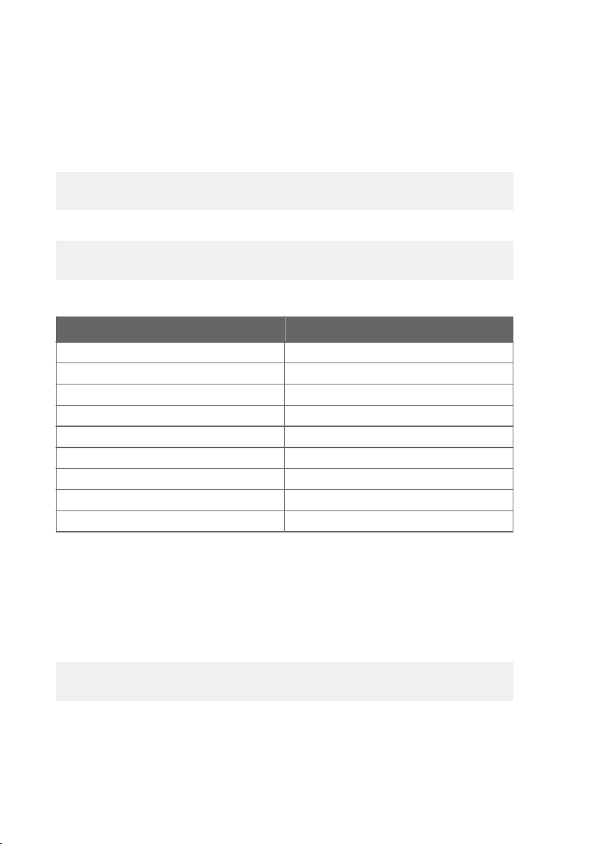
Table 9 Error Messages on ERRS Command
ERRS Command Response Corresponding Error
T MEAS error
F meas error
Flash crc failure
Parameter flash check sum error
INFOA check sum error
SCOEFS check sum error
CURRENT check sum error
Voltage error
General flash failure w/r
Temperature measurement error. [44]
Humidity measurement error. [45]
Firmware checksum mismatch. [49]
Device settings corrupted. [50]
Additional configuration settings corrupted. [51]
Sensor coecients corrupted. [52]
Main configuration settings corrupted. [53]
Supply voltage out of range. [55]
Non-volatile memory read/write failure. [57]
Refer to Error Messages in Insight Software (page 67) for more information about the error
states.
7.5.6 Show Serial Number
SNUM<cr>
Example:
snum
Serial number : G4060003
7.5.7 Show Command List
Use the HELP command to show a list of serial commands:
46
Page 49

HELP<cr>
Example:
help
?
ADDR
AERR
ALARM
AMODE
AOVER
AOUT
ASEL
ATEST
CLOSE
ERRS
FILT
FORM
FRESTORE
GAS
HELP
INTV
L
LI
OPEN
PRES
R
RESET
SDELAY
SEND
SERI
SMODE
SNUM
SYSTEM
TIME
UNIT
VERS
XPRES
Chapter 7 – Serial Communication
7.6
Configuring Analog Output
7.6.1 Set Analog Output Parameters and Scaling
Use the ASEL command to show or set the output parameter and the scaling of the analog
output.
ASEL [parameter] [lowlimit highlimit]<cr>
47
Page 50
DMT143 User Guide M211435EN-J
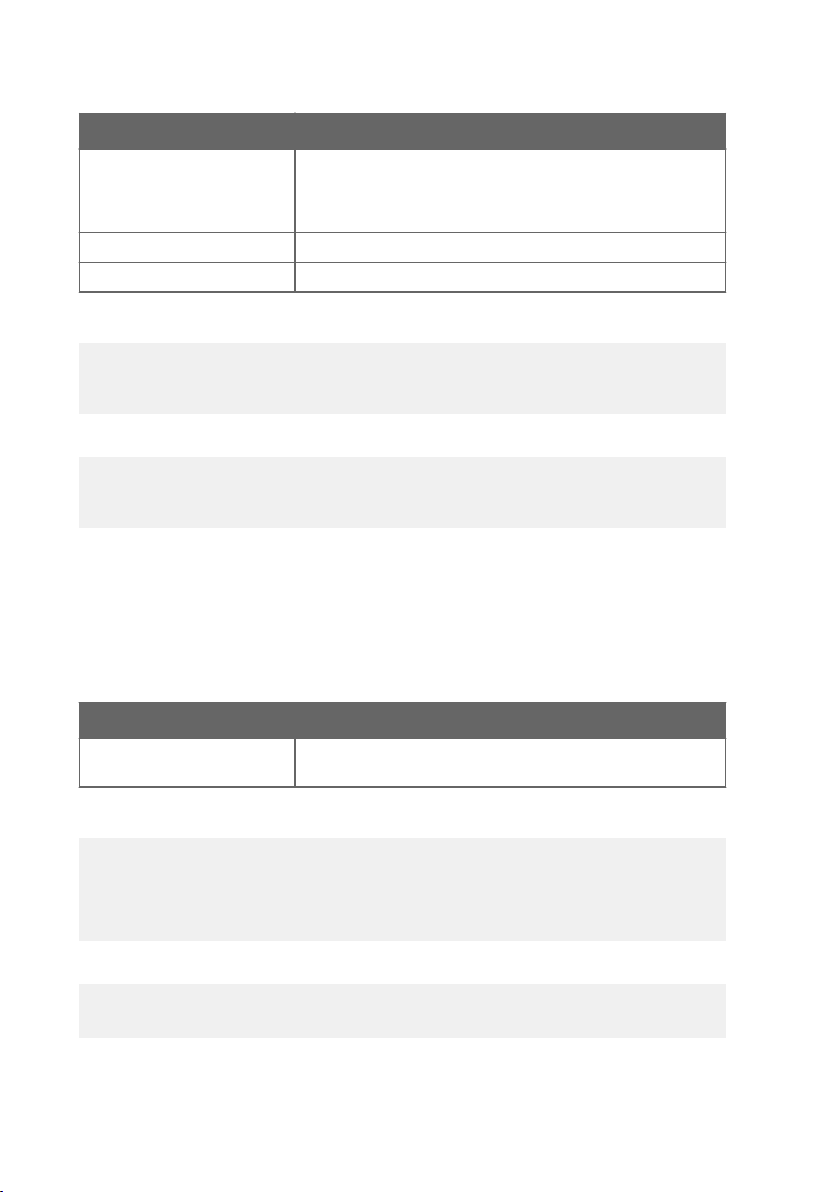
Syntax Description
parameter
Parameter that is output on analog channel. Available parameters
are TDF, TDFA, H2O. If the transmitter has been ordered from
Vaisala with a relative humidity output on the analog channel,
also parameter RH is available.
lowlimit
highlimit
Lower limit of parameter scaling.
Higher limit of parameter scaling.
Example (show current settings):
asel
Ch1 Tdf lo : -80.00 'C ?
Ch1 Tdf hi : 20.00 'C ?
Example (change output parameter to H2O, set low and high limits):
asel h2o 0 6000
Ch1 H2O lo : 0.00 ppm
Ch1 H2O hi : 6000.00 ppm
7.6.2 Set Analog Output Error Notification
If the transmitter is malfunctioning, the analog output is set to a specified level. This overrides
the normal measurement output of the channel. The default level is 0 mA or 0V, according to
the output type. You can set the level using the AERR command.
AERR [level]<cr>
Syntax
level
Description
Error level for the analog output channel. Available range
depends on the output type (check with AMODE command).
Example (check settings):
amode
Ch1 output : 4 ... 20 mA
aerr
Ch1 error out : 0.000 mA
Example (set analog channel error level to 20 mA):
aerr 20
Ch1 error out : 20.000 mA
48
Page 51

Chapter 7 – Serial Communication
The error output value is displayed only when there are minor electrical faults
such as a sensor damage. When there is a severe device malfunction, the error
output value is not necessarily shown.
7.6.3 Extend Analog Output Range
Use the AOVER command to allow the analog output channels to exceed their specified range
by 10 %. The scaling of the parameter remains as before; the extra range is used for additional
measurement range in the high end of the scale.
AOVER [ON/OFF]<cr>
Example (turning AOVER on):
aover on
AOVER : ON
The following example illustrates how the analog output is aected. The channel outputs T
d
with voltage output 0 … 5 V (-80 … -30 °C). After giving the AOVER ON command, the range is
0 … 5.5 V (-80 … -25 °C). Note that the -30 °C Td point is still at 5 V.
7.6.4 Test Analog Output
You can test the operation of the analog output with the ATEST command by forcing the
output to a given value. You can then measure the output with a calibrated multimeter. After
testing the output, give the ATEST command again to exit the test mode.
ATEST [level]<cr>
Syntax
level
The command output shows the test value of the analog output as well as diagnostic
information that may be useful to Vaisala Service Center if there is a problem with the analog
output.
Example (enabling analog output test mode, setting level to 20 mA):
atest 20
20.000 27407
Example (disabling analog output test mode, resuming normal output):
atest
0.000 15831
Description
Level for analog output channel. Analog output type determines
if the value is V or mA.
49
Page 52

DMT143 User Guide M211435EN-J
7.6.5 Enable or Disable Analog Output
Use the AOUT command to enable or disable the analog output channel.
AOUT [ON/OFF]<cr>
Example (turn analog output o):
aout off
AOUT : OFF
7.7 Serial Line Output Commands
7.7.1 Start Measurement Output
Use the R command to start the continuous outputting of measurement values as an ASCII text
string to the serial line. The format of the measurement message is set with the FORM
command.
R<cr>
Example (measurement message in default format):
r
Tdf= 17.75 'F Tdfatm= -5.25 'F H2O= 954 ppm
Tdf= 17.23 'F Tdfatm= -5.72 'F H2O= 930 ppm
Tdf= 17.06 'F Tdfatm= -5.88 'F H2O= 922 ppm
Tdf= 16.97 'F Tdfatm= -5.96 'F H2O= 918 ppm
...
Outputting the results continues in intervals issued with the command INTV until stopped.
7.7.2 Stop Measurement Output
You can stop the measurement output by pressing the ESC key.
7.7.3 Set Output Interval
Use the INTV command to change the output interval of the automatically repeating
measurement messages. The measurement messages are repeated in the RUN mode, or after
the R command has been given.
INTV [n xxx]<cr>
Syntax
n
xxx
50
Description
time interval, range 0 ... 255
time unit = "S", "MIN", or "H"
Page 53

Chapter 7 – Serial Communication
The shortest output interval (with n = 0) outputs the measurement messages as quickly as the
transmitter’s internal measurement cycle produces them, without additional delay.
Example:
intv 1 min
Output interval: 1 MIN
7.7.4 Output a Reading Once
Use the SEND command to output a single measurement message. The output message is sent
in the format that has been set using the FORM command.
SEND [address]<cr>
Syntax Description
address
Example:
send
Tdf= 16.71 'F Tdfatm= -6.19 'F H2O= 907 ppm
Address of the transmitter, range 0 ... 255.
Specifying the address is only necessary if the target transmitter
is in POLL mode, and has not been accessed with the OPEN
command.
7.8
Configuring Measurement Parameters
7.8.1 Set Measurement Output Format
Use the serial line command FORM to change the measurement message sent by the
transmitter. You can freely define the output message to include the desired parameters,
formatting options, text strings, and additional fields.
FORM [modifier string]<cr>
Syntax
modifier string
Description
String of parameters and modifiers that defines the output
format, length 1 ... 153 characters. Maximum length may be
shorter when text strings are used.
51
Page 54
DMT143 User Guide M211435EN-J
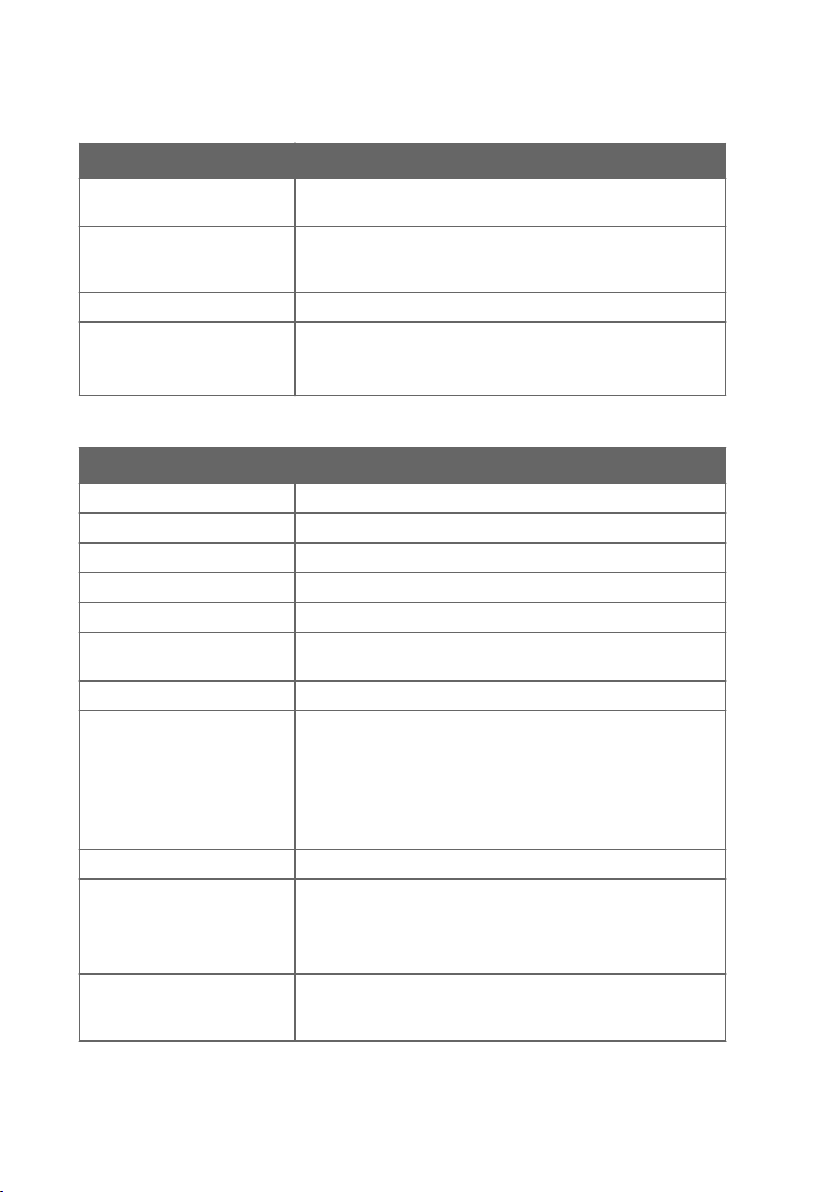
Table 10 FORM Command Parameters
Measured Parameter Abbreviation in FORM Command
Dew point/frost point
Tdf
temperature
Dew point/frost point
Tdfa
temperature, converted to
atmospheric pressure
ppm moisture, by volume
Relative humidity
H20
RH
RH is available only if transmitter has been ordered from Vaisala
with a relative humidity output on the analog channel.
Table 11 FORM Command Modifiers
Modifier Description
x.y
#t
#r
#n
""
#xxx
Length modifier (number of digits and decimal places)
Tabulator
Carriage return
Line feed
String constant, length 1 ... 15 characters
ASCII code value (decimal) of a special character; for example,
#027 for ESC
ADDR
ERR
Transmitter address (0 ... 255)
Currently active transmitter errors in a four-bit field:
bit0bit1bit2bit3bit4
• bit0 T MEAS error
• bit1 N/A
• bit2 Fmeas error
• bit3 Flash csum error
SN
STAT
Transmitter serial number
Transmitter status in a one-character field:
• h – sensor heating active
• H – purge active
• A – autocalibration active
Ux
Shows the name of the measurement unit using “x” number of
characters. For example, U3 shows the name of the measurement
unit with 3 characters
52
Page 55

Chapter 7 – Serial Communication
Modifier Description
CS2
Modulus-256 checksum of message sent so far, ASCII encoded
hexadecimal notation
CS4
Modulus-65536 checksum of message sent so far, ASCII encoded
hexadecimal notation
CSX
NMEA xor-checksum of message sent so far, ASCII encoded
hexadecimal notation
FORM Command Examples
You can return to the default format using the "FORM /" command.
Example of default output (continuous output from RUN mode):
Tdf= -9.80 'C Tdfatm= -9.80 'C H2O= 2618 ppm
Tdf= -9.80 'C Tdfatm= -9.80 'C H2O= 2617 ppm
...
Command to set output format as Tdf and ppm with Modulus-256 checksum:
form 3.2 "Tdf=" Tdf U3 6.0 "H2O=" H2O " " U5 CS2 \r \n
Output example:
Tdf= -9.74'C H2O= 2632 ppm C4
Tdf= -9.72'C H2O= 2636 ppm C6
...
Command to set output format as Tdf and ppm, with start of text (ASCII character 002)
and end of text (003) ASCII codes, and without line feed and carriage return at the end:
form #002 3.2 "Tdf="Tdf U3 6.0 "H2O=" H2O " " U5 #003
Output example (ASCII codes not visible here):
Tdf= -9.57'C H2O= 2671 ppm Tdf= -9.59'C H2O= 2666 ppm
Tdf= -9.61'C H2O= 2662 ppm Tdf= -9.62'C H2O= 2660 ppm
...
7.8.2 Set Measurement Filtering
Use the FILT command to view or set the speed at which the latest measurement result is
integrated into the output readings. The command aects both analog output and serial line
output.
FILT [a.aaaaa]<cr>
53
Page 56
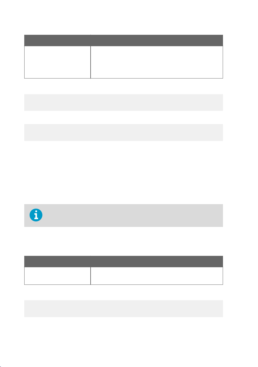
DMT143 User Guide M211435EN-J
Syntax Description
a.aaaaa
Range 0.00001 ... 1.0
1.0 = No filtering, latest measurement is output without averaging
0.5 = Average of last two measurements
0.1 = Average of approx. 16 measurements (default)
Example (show current setting):
filt
Filter : 0.10000 ?
Example (set filtering to 0.5):
filt 0.5
Filter : 0.50000
7.8.3 Set Pressure Compensation Value
The pressure of the measured system must be known for accurate dew point and ppm
measurement. The pressure compensation value has been set at the factory according to the
order form. You can view and set a new value using the PRES command.
Command XPRES should be used if the value is changed frequently. The value set using the
XPRES command overrides the PRES value, but it is not retained at reset. When the XPRES is
set to 0, the last value set with PRES is used instead.
It is enough to set an approximate pressure value (±1 bar) to meet the accuracy
specification of the DMT143.
PRES [pp.ppppp]<cr>
XPRES [pp.ppppp]<cr>
Syntax
pp.ppppp
Description
Absolute pressure (bara) in the measuring point.
Range 0.001 ... 50 bar.
Example (set pressure compensation value to 3 bar):
pres 3
Pressure : 3.000 bar
54
Page 57
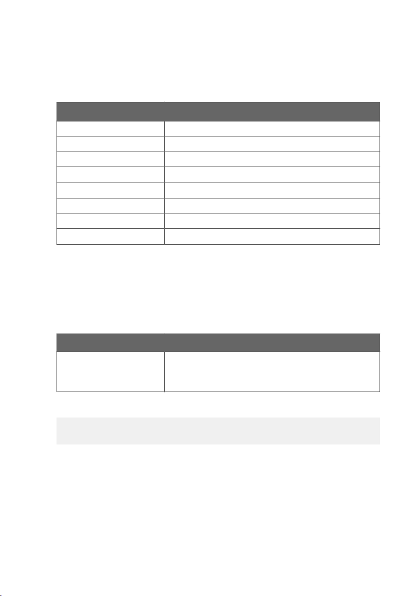
Chapter 7 – Serial Communication
The pressure conversion coecients from other pressure units to bars is given in the table
below.
Table 12 Pressure Conversion Coecients
From To bar
²
PaN/m
a
0.00001
mmHg torr 0.001333224
inHg 0.03386388
mmH2O 0.00009806650
inH2O 0.002490889
atm 1.01325
at 0.980665
psi
a
For example: 29.9213 inHg = 29.9213 × 0.03386388 = 1.01325 bar
0.06894757
a.
7.8.4 Select Unit
Use the UNIT command to select metric or non-metric output units.
UNIT [x]<cr>
Syntax
x
Description
Selects the unit type to output:
m = metric units, for example, Celsius
n = nonmetric units, for example, Fahrenheit
Example:
unit m
Units : Metric
7.8.5 View User Adjustment Parameters
Use the L command to view the current user adjustment parameters that are aected by the
LI command and the MI70 indicator (Tdf oset only). This command is useful for checking the
currently applied correction.
L<cr>
The output values are as follows:
55
Page 58
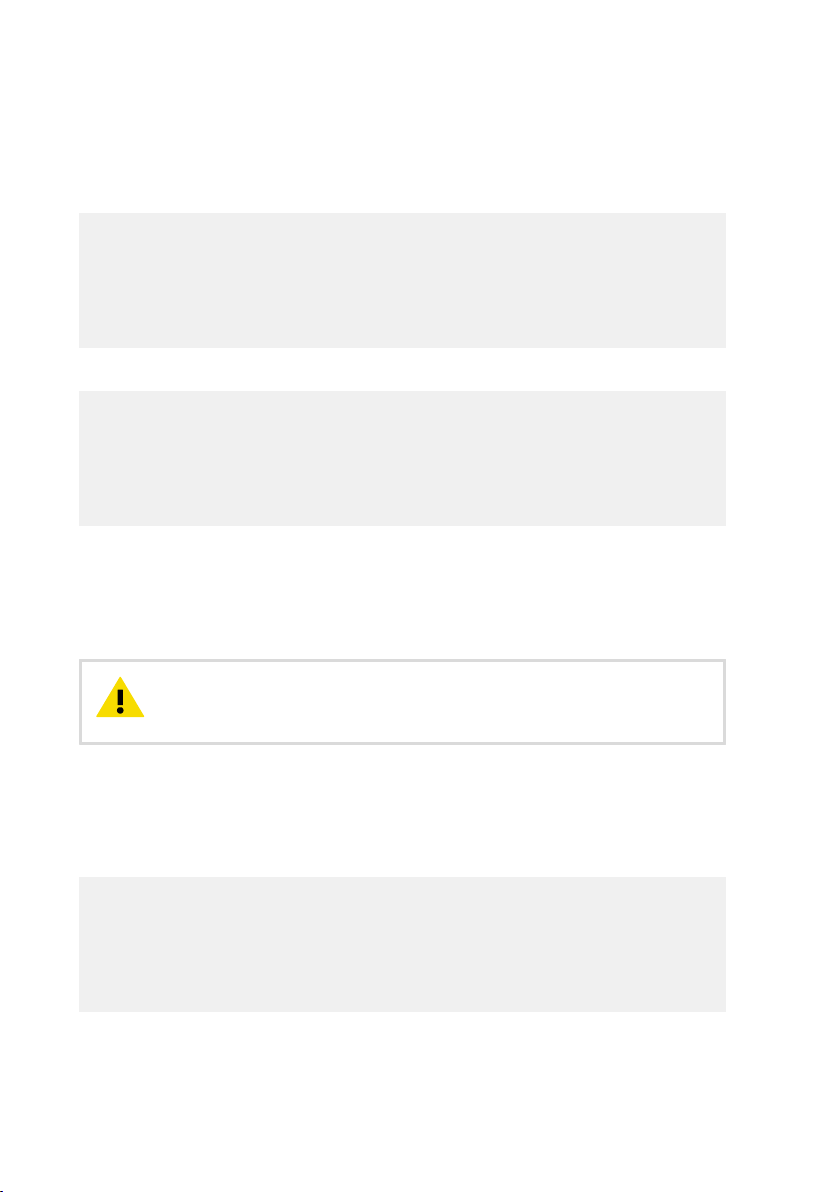
DMT143 User Guide M211435EN-J
• RH oset and gain
• T oset and gain
• Tdf oset and gain
Example (shows default values, no user adjustment done):
l
RH offset : 0.00000000E+00
RH gain : 1.00000000E+00
T offset : 0.00000000E+00
T gain : 1.00000000E+00
Tdf offset: 0.00000000E+00
Tdf gain : 1.00000000E+00
Example (shows that a -1.2 °C Tdf oset has been applied by the user):
l
RH offset : 0.00000000E+00
RH gain : 1.00000000E+00
T offset : 0.00000000E+00
T gain : 1.00000000E+00
Tdf offset: -1.20000000E+00
Tdf gain : 1.00000000E+00
7.8.6 Set User Adjustment Parameters
Use the LI command to set the user adjustment parameters directly. This command is useful
for restoring the desired adjustments, and removing the eects of user adjustment without
having to perform the factory reset.
CAUTION!
This command is provided primarily for applying an oset to the Tdf
measurement. Do not adjust the other parameters unless instructed to do so by
a Vaisala Service Center.
LI<cr>
After entering the command, you will be prompted to enter new values one at a time. Press
ENTER without giving a value to move to the next parameter.
Example (shows a +0.8 °C Tdf oset being applied):
li
RH offset : 0.00000000E+00 ?
RH gain : 1.00000000E+00 ?
T offset : 0.00000000E+00 ?
T gain : 1.00000000E+00 ?
Tdf offset: 0.00000000E+00 ?
Tdf gain : 1.00000000E+00 ?
56
Page 59
Chapter 7 – Serial Communication
7.9 Configuring Serial Line Operation
7.9.1 Set Serial Line Operating Mode
Use the SMODE command to set the start-up operating mode of the serial line.
SMODE [mode]<cr>
Syntax Description
mode
Table 13 Selection of Output Modes
Mode Measurement Output Available Commands
STOP Only with the SEND command. All (default mode).
RUN Automatic output. Only command S.
POLL Only with the SEND [addr]
command.
MODBUS No automatic output. Measurement outputs must be read from
STOP, RUN, POLL, or MODBUS.
SEND [addr] and OPEN [addr].
Other commands available after opening
a line to the transmitter using the OPEN
command.
Use with RS-485 buses where multiple
transmitters can share the same line.
the transmitter using the Modbus
protocol.
Selected output mode will be activated at next reset or power up.
Example:
smode poll
Serial mode : POLL
More Information
‣
Accessing Serial Interface in Devices with Modbus Output (page 42)
7.9.2 Set Serial Line Settings
Use the SERI command to set the serial line settings. The new settings will be taken into use
when the transmitter is reset or powered up.
57
Page 60
DMT143 User Guide M211435EN-J
If you have altered the DMT143 serial line settings and start using the MI70 handheld indicator, always switch o the other power supply (disconnect “Analog”
cable if in use) before powering up the MI70.
SERI [b p d s]<cr>
Syntax Description
b
p
d
s
baud rate (4800, 9600, or 19200)
parity (n = none, e = even, o = odd)
data bits (7 or 8)
stop bits (1 or 2)
Example (set serial line to 9600 baud, no parity, 7 data bits, and 1 stop bit):
seri 9600 e 7 1
SCI Baud P D S: 9600 E 7 1
More Information
‣
Operation with DM70 Handheld Dew Point Meter (page 38)
7.9.3 Set Transmitter Address
To operate in the POLL mode, the transmitter must have an address. If multiple transmitters
share the same serial line, each transmitter must have a dierent address.
ADDR [address]<cr>
Syntax
address
Description
Transmitter address, range 0 ... 255.
Example:
addr
Address : 0 ?
More Information
‣
Set Serial Line Operating Mode (page 57)
58
Page 61
Chapter 7 – Serial Communication
7.9.4 Set Serial Line Response Time
With the SDELAY command you can set delay (response time) of the serial line, or view the
currently set delay value.
SDELAY [delay]<cr>
Syntax Description
delay
Example (set delay to 120 milliseconds):
sdelay 30
Serial delay : 30
7.10
Other Commands
Serial line delay, range 0 … 255. One unit of delay corresponds to
4 milliseconds.
7.10.1 Opening the Transmitter in POLL Mode
Use the OPEN command to connect to a transmitter that is in POLL mode.
OPEN [address]<cr>
Syntax
address
Example (target transmitter in POLL mode, with address 5):
open 5
DMT143 5 line opened for operator commands
Description
Transmitter address, range 0 ... 255.
7.10.2 Closing the Connection to a Transmitter in POLL Mode
The CLOSE command closes the connection to a transmitter.
CLOSE<cr>
Example:
close
line closed
59
Page 62

DMT143 User Guide M211435EN-J
7.10.3 Configure the Alarm LED
Use the ALARM command to configure the alarm LED functionality.
ALARM [LED] [Alarm] [Level]<cr>
Syntax Description
LED
Alarm
Level
Example (show current settings):
alarm ?
LED display : OFF
Alarm display : OFF
Setpoint Td(°C): -10.00
Enable or disable the entire LED functionality.
Allowed values:
ON - Enable the LED functionality.
OFF - Turn o the LED completely.
Enable or disable the dew point alarm.
Allowed values:
ON - Enable the dew point alarm.
OFF - Turn o the dew point alarm.
Dew point temperature above which the alarm LED will turn red.
The LED will turn green when the measured dew point
temperature falls below this level.
Range -70 ... +60 °C Tdf.
Example (change values line by line, enter to skip line):
alarm
LED display : OFF ? on
Alarm display : OFF ? on
Setpoint Td(°C): -10.00 ? -40
Example (change alarm level to -40 °C Tdf):
alarm on on -40
LED display : ON
Alarm display : ON
Setpoint Td(°C): -40.00
Example (turn o the dew point alarm only):
60
Page 63

Chapter 7 – Serial Communication
alarm on off
LED display : ON
Alarm display : OFF
Setpoint Td(°C): -40.00
Example (turn o the LED completely):
alarm off
LED display : OFF
More Information
‣
Alarm LED (page 20)
7.10.4 Reset Transmitter
Use the RESET command to reset the transmitter.
RESET<cr>
When the RESET command is given, the transmitter will restart as if it had just been powered
on. All transmitter settings are retained. The serial line mode of the transmitter will be set to
the mode that was set using the SMODE command.
7.10.5 Restore Factory Settings
Use the FRESTORE command to restore the transmitter to its factory configuration. All user
settings will be lost.
FRESTORE<cr>
After using the FRESTORE command, reset the transmitter using the RESET
command.
61
Page 64
DMT143 User Guide M211435EN-J
8. Maintenance
8.1 Periodic Maintenance
8.1.1 Cleaning
You can clean the body of the transmitter by wiping with a moistened lint-free cloth. Do not
immerse the transmitter in liquid, and do not use cleaning agents or solvents.
8.1.2 Calibration
DMT143 is fully calibrated as shipped from the factory. The recommended calibration interval is
2 years. If there is a reason to believe that the device is not within the accuracy specifications,
you can perform a field check using the DM70 handheld dew point meter.
If the field check indicates that the DMT143 is not within its accuracy specifications, contact a
Vaisala Service Center or your local Vaisala representative to have the DMT143 adjusted.
8.1.3 Changing the Filter
Replace the filter if it is contaminated. New filters are available from Vaisala.
CAUTION!
sensor when the filter is removed.
CAUTION!
for vacuum applications installed, note that it has tapered threads and is not
meant to be removed on site. Trying to forcefully loosen the filter may damage
the transmitter instead. The filter replacement instructions below are for the
standard sintered filter DRW010335SP with parallel threads.
CAUTION!
sure that the pressure of the chamber is equalized with the ambient pressure
prior to removing the transmitter. When the transmitter is removed for
maintenance, cap the hole with a capped nut. This way, the chamber can be
pressurized although the transmitter is not in place.
Plugs are available from Vaisala for ISO and NPT threaded connections.
When replacing the filter, wear clean gloves to avoid depositing dirt or oil on the filter. Inspect
the sealing ring for damage (used with ISO thread only), and replace it if necessary.
62
Be careful when changing the filter, since it is easy to break the
If the transmitter has the optional stainless steel filter HM47453SP
If the transmitter is installed in a pressurized chamber, always make
Page 65
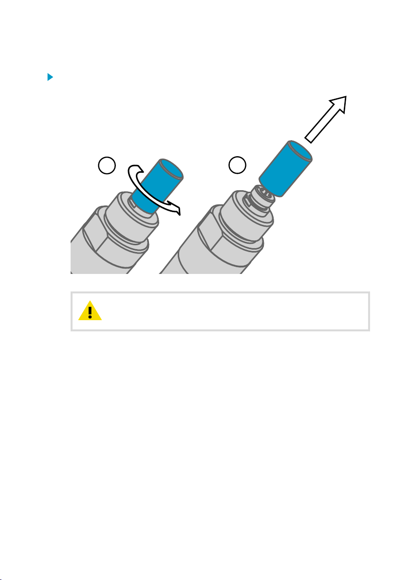
Replace the filter as follows:
1
2
1. Turn the filter counterclockwise until it is loose.
2. Pull the filter straight out carefully.
Do not damage the sensor.CAUTION!
Chapter 8 – Maintenance
3. Take the new filter, and insert it to the filter thread.
4. Tighten the new filter to 5 Nm by turning it clockwise.
More Information
‣
Spare Parts and Accessories (page 73)
8.1.4 Field Check Using DM70 Handheld Dew Point Meter
Vaisala recommends the following equipment for field checking:
• A fully charged MI70 indicator (the measurement display that is included in the DM70
package).
• A calibrated reference probe that is suitable for the intended measurement environment
and dew point range. The DMP74B probe is recommended for checking the dew point
temperature measurement accuracy.
• You also need a connection cable (Vaisala order code 219980SP) to connect the DMT143
to the MI70 indicator.
63
Page 66
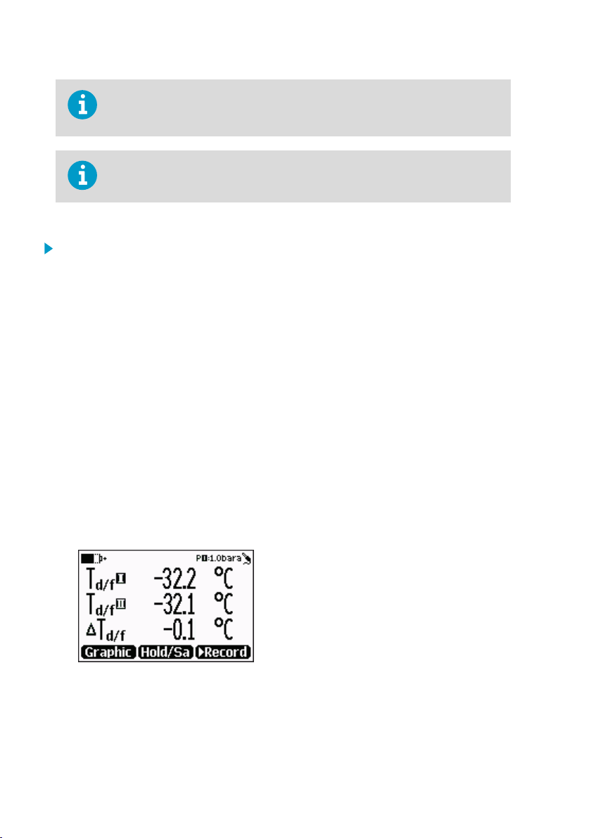
DMT143 User Guide M211435EN-J
In the following procedure, the readings of the transmitter and the reference
probe are checked simultaneously. You can also check the reference probe and
the DMT143 separately if they cannot be connected at the same time.
The messages from the transmitter will appear in English even if the MI70 has
been set to another language.
Perform the check as follows:
1. Place the reference probe and the DMT143 in the reference environment.
2. Connect the reference probe and the DMT143 to the MI70 indicator:
• Reference probe to Port I
• DMT143 to Port II
3. If you have altered the DMT143 serial port settings, switch o the other power supply
(disconnect “Analog” cable if in use) before powering up the MI70. Note that this powers
o the transmitter, and it will carry out the startup sequence when powered on again.
4. Turn on the MI70 indicator. Never connect or disconnect the MI70 indicator while it is
powered on, as this may cause incorrect values to be displayed.
5. Check and adjust the environment settings if prompted. Refer to the DM70 User’s Guide
for the settings of the DMP74B probe.
6. Disable the Auto power o function of the MI70 indicator to prevent the indicator from
powering o in the middle of the check. Check the setting in the Settings - User Interface
menu, and change if necessary.
7. The MI70 can display three parameters at one time. To compare the readings of the
DMT143 and the reference probe, select the desired parameter from the Display –
Quantities and Units menu of the MI70.
Select the same parameter from port I and II, and the delta parameter that shows the
dierence between the two. For example, ∆T
shows the dierence in dew point
d/f
between the two probes.
8. After the measurement has stabilized, check the dierence between the readings. It will
give you an indication of the approximate drift of the DMT143 and its need for calibration.
The dierence between the readings should be no greater than the combined
measurement uncertainty of the DMT143 and the reference probe.
9. Write down the results and repeat the comparison for each parameter you want to check.
64
Page 67

Chapter 8 – Maintenance
10. If adjustment is required, contact a Vaisala Service Center or your local Vaisala
representative to have the DMT143 adjusted.
More Information
‣
DMT143 Startup Sequence (page 19)
8.2 Repair Maintenance
CAUTION!
and is not designed to be opened. Opening the transmitter will void the
warranty.
If there is a problem with your transmitter that you are unable to solve yourself or with the
help of Vaisala Helpdesk, contact a Vaisala Service Center. In case of mechanical or electrical
failure, the Service Center may replace the transmitter with a new one.
More Information
‣
Troubleshooting (page 66)
‣
Technical Support (page 85)
The transmitter body does not have user serviceable parts inside,
65
Page 68

DMT143 User Guide M211435EN-J
9. Troubleshooting
9.1 Solving Typical Problems
Some problems can be solved by simply resetting the transmitter. You can reset the
transmitter by disconnecting the power or issuing the RESET command using the service port.
If resetting does not help, and if the problem is related to transmitter software or settings, you
can restore the factory configuration of the transmitter by issuing the FRESTORE command. If
you are unable to solve your problem with the transmitter, contact Vaisala.
Table 14 Troubleshooting Table
Problem Possible Causes and Solutions
One of the following occurs:
• Transmitter outputs stars "****" on serial line
instead of measurement data.
• Unavailable value in Modbus mode.
• Analog signal is at error level.
Unable to access transmitter on the RS-485 line. Possible causes: Incorrect wiring, unknown serial
Analog output seems to be stuck, the
measurement is not changing.
Dew point alarm LED is red even though the
measured dew point is not high.
Possible causes: damaged sensor, incorrect
supply voltage, and unsuitable measurement
environment.
Power cycle or reset the transmitter, and see if
the problem continues. Check the active errors
using Vaisala Insight PC software or the ERRS
command. Check the power supply.
settings, transmitter in POLL or MODBUS mode
with unknown address.
Check wiring. Check communication settings
with Vaisala Insight PC software. Try connecting
as instructed in section Accessing Serial
Interface in Devices with Modbus Output
(page 42).
Possible causes: Sensor diagnostics in progress
(autocal or purge), malfunction error active.
Check the active errors using Vaisala Insight PC
software or the ERRS command. Wait for the
diagnostics to complete.
Possible causes: the alarm limit may be set
incorrectly for your application.
Check and correct using Vaisala Insight PC
software, serial line, or MI70 indicator.
More Information
‣
Vaisala Insight Software (page 36)
‣
Connecting to the Serial Interface (page 41)
‣
Technical Support (page 85)
66
Page 69

Chapter 9 – Troubleshooting
9.2 Error Messages in Insight Software
Table 15 Error Messages in Insight Software
Error Likely Cause Suggested Solution
Temperature
measurement error.
[44]
Humidity
measurement error.
[45]
Supply voltage out of
range. [55]
Firmware checksum
mismatch. [49]
Device settings
corrupted. [50]
Additional
configuration settings
corrupted. [51]
Sensor coecients
corrupted. [52]
Main configuration
settings corrupted.
[53]
Non-volatile memory
read/write failure. [57]
Temperature sensor is
short circuited,
damaged, or missing.
Humidity sensor is wet,
damaged, or missing.
Supply voltage is too
low.
Internal transmitter
failure.
Check that the legs of the temperature sensor
are not short circuited. Contact a Vaisala Service
Center if the sensor is damaged.
Wait for the humidity sensor to dry, or remove
the filter and gently dry the sensor and the filter
with clean instrument air. Contact a Vaisala
Service Center if the sensor is damaged.
Check and correct the power supply and wiring.
Power-cycle the device, and if necessary, restore
the factory settings. If the error remains, contact
a Vaisala Service Center.
In case of constant error, contact a Vaisala Service Center.
More Information
‣
Technical Support (page 85)
9.3
Error Codes in MI70 Handheld Meter
If several errors are active at the same time, the MI70 shows the sum of currently active error codes.
The label "
" might not be displayed in MI70.
hex
67
Page 70

DMT143 User Guide M211435EN-J
Refer to Error Messages in Insight Software (page 67) for more information about the error states.
Table 16 Error Codes in MI70
Transmitter Error Code in MI70 Corresponding Error
1
hex
2
hex
40
hex
80
hex
100
hex
200
hex
800
hex
10000
20000
hex
hex
Temperature measurement error. [44]
Humidity measurement error. [45]
Device settings corrupted. [50]
Additional configuration settings corrupted. [51]
Sensor coecients corrupted. [52]
Main configuration settings corrupted. [53]
Supply voltage out of range. [55]
Non-volatile memory read/write failure. [57]
Firmware checksum mismatch. [49]
9.4 Unknown Serial Settings
You can check the current serial settings of your transmitter by connecting to the serial line, or
with Vaisala Insight software.
More Information
‣
Accessing Serial Interface in Devices with Modbus Output (page 42)
‣
Vaisala Insight Software (page 36)
68
Page 71
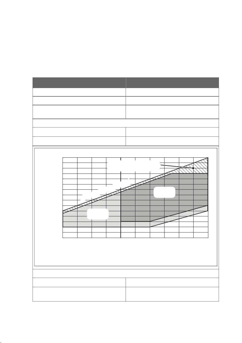
0 20
20
0
10
30
-10
-20
-30
10 30 40 50 60
40
Dew point temperature (°C)
Temperature of measured gas (°C)
-40 -30 -20 -10
-40
-50
-60
-70
50
60
-80
-90
Accuracy
±3 °C Td*
Not recommended for
continuous measurement
Accuracy
±2 °C Td
Water vapo
r saturation l
ine
* > 12 bar, accuracy ±4 °C Td
Chapter 10 – Technical Data
10. Technical Data
10.1 DMT143 Specifications
Table 17 Measurement Performance
Property Description/Value
Sensor Vaisala DRYCAPâ 180D
Sensor protection Stainless steel sintered filter
Recommended calibration interval to confirm
the specified accuracy
Dew Point Temperature
Measurement range (typical) -70 … +60 °C (-94 … +140 °F) T
Accuracy in air or N2
1)
2 years
±2 °C (±3.6 °F) Td (see graph below)
d
Analog output scalings:
Option 1 -80 … +20 °C (-112 … +68 °F) T
Option 2 -80 … +20 °C (-112 … +68 °F) Td dew point at
d
ambient pressure
69
Page 72
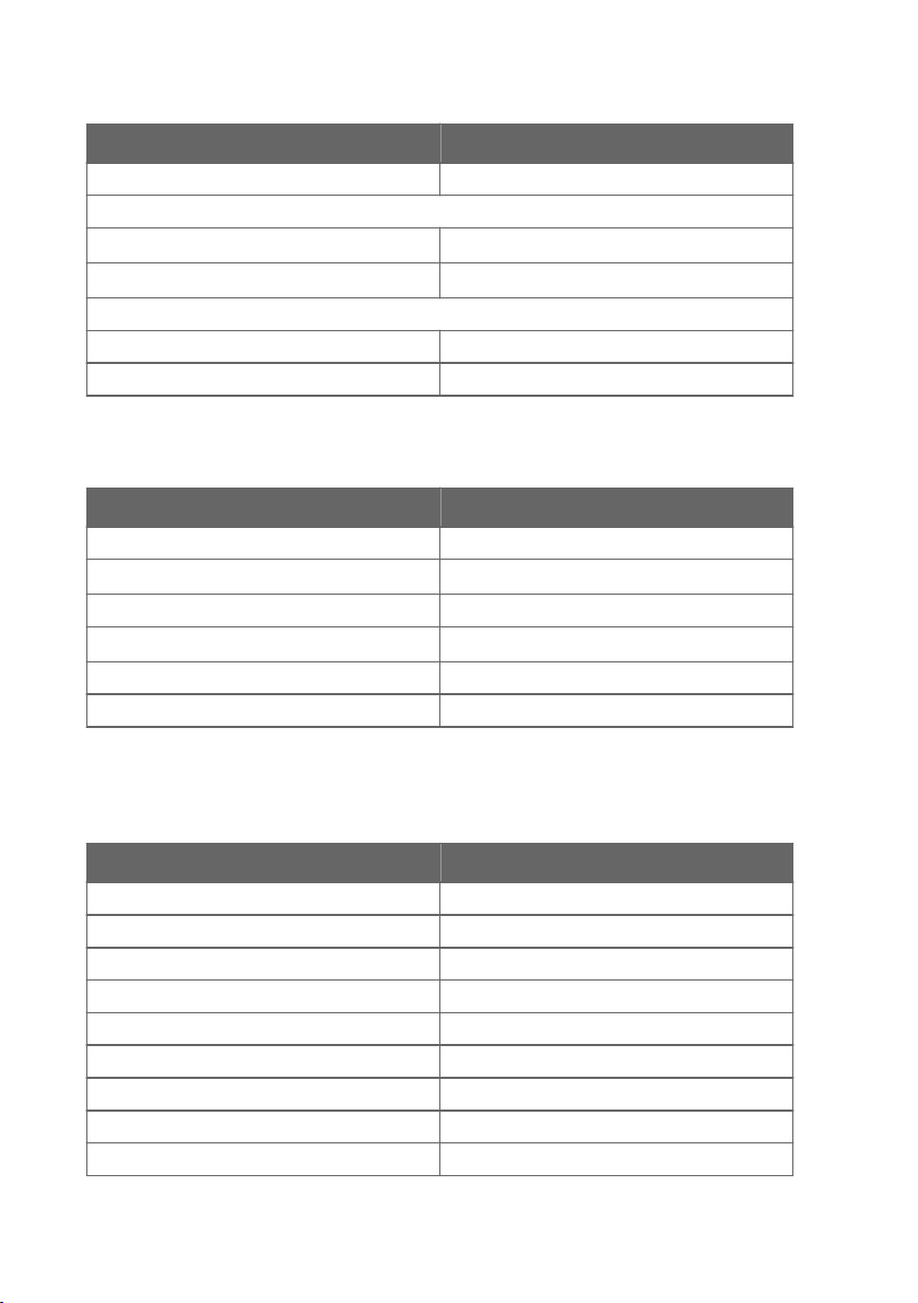
DMT143 User Guide M211435EN-J
Property Description/Value
Option 3 Free scaling
Response time 63 % [90 %] at +20 °C gas temperature and 1 bar pressure and 1 liter/min flow rate:
-70 → -20 °C Td (-94
→ -4 °F Td)
5 s [15 s] (typical)
-20 → -70 °C Td (-4 → -94 °F Td) 45 s [10 min] (typical)
Water Concentration by Volume (ppm)
Measurement range (typical) 10 … 40 000 ppm
Accuracy at +20 °C (+68 °F), 1 bar 1 ppm + 20 % of reading
1) When the dew point is below 0 °C (32 °F), the transmitter outputs frost point.
Table 18 Operating Environment
Property Description/Value
Measured gases Non-corrosive gases
Temperature
1)
-40 … +60 °C (-40 … +140 °F)
Relative humidity 0 … 100 % RH
Pressure
1)
0 … 50 bara (7
25 psia)
Sample flow rate No eect for measurement accuracy
Storage temperature -40 … +60 °C (-40 … +140 °F)
1) For extended temperature below 0 °C (+32 °F) or pressure above 20 bara (2
90 psia) the
supply voltage must be 24 … 28 VDC.
Table 19 Inputs and Outputs
Property Description/Value
Analog output (scalable) 4 … 20 mA (3-wire), 0 … 1 V / 5 V, 1 … 5 V
Resolution for current output 0.002 mA
Resolution for voltage output 0.3 mV
Accuracy for current output at +20 °C ± 0.05 mA
Accuracy for voltage output at +20 °C ± 0.01 V
Operating voltage with voltage output 12 … 28 VDC
Operating voltage with current output 18 … 28 VDC
Load for current output Max. 500 Ω
Load for voltage output Min. 10 kΩ
70
Page 73
Chapter 10 – Technical Data
Property Description/Value
Typical temperature dependence 0.005 % of span/°C
Digital output RS-485, non-isolated
Vaisala Industrial Protocol
Modbus RTU protocol
Connector 4-pin M8 (IEC 60947-5-2)
Supply Current at +20 °C (Uin 24 VDC)
Normal measurement Typical 10 mA + load current
During self-diagnostics Typical 220 mA pulsed
Table 20 Mechanical Specifications
Property Description/Value
Mechanical connection ISO G1/2 in or NPT 1/2
Housing material Stainless steel (AISI316L)
Weight G-thread version 90 g (3.2 oz)
NPT-thread version 100 g (3.5 oz)
Table 21 Compliance
Property Description/Value
IP rating IP66
NEMA rating NEMA 4
EMC compliance EN61326-1, Electrical equipment for
measurement, control and laboratory use - EMC
requirements - Industrial environment
71
Page 74
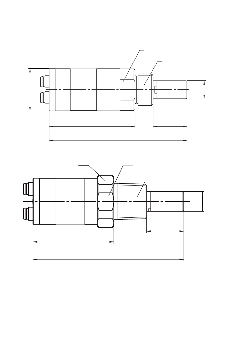
AW24
G1/2” ISO228/1
Ø28 [1.10]
Ø12
57 [2.24] 22.5 [0.89]
91.6 [3.61]
[0.47]
Ø32 [1.26]
AW30
NPT1/2”
Ø12
22.5 [0.89]
49.1 [1.93]
91.6 [3.61]
[0.47]
DMT143 User Guide M211435EN-J
10.2 Dimensions
Figure 20 DMT143 Dimensions – Model with ISO Thread
Figure 21 DMT143 Dimensions – Model with NPT Thread
72
Page 75
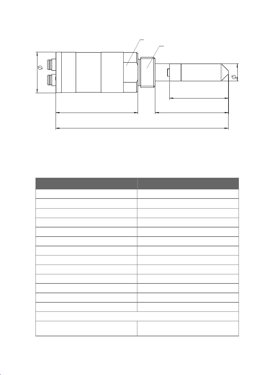
AW24
G1/2" ISO228/1
12
28
120
51
41
57
Chapter 10 – Technical Data
Figure 22 DMT143L Dimensions
10.3
Spare Parts and Accessories
Table 22 Spare Parts and Accessories
Item Order Code
Connection cable for DM70 219980SP
USB cable for PC connection
Loop powered external display 226476
Loop powered external display with relays 234759
Installation flange ISO ½ DM240FASP
Sintered filter (DMT143) DRW010335SP
Stainless steel filter (DMT143, DMT143L) HM47453SP
Stainless steel sintered filter (38 um) (DMT143L) HM47280SP
Mounting nut MOUNTINGNUTSP
Plug kit (ISO 1/2") 218773
Plug kit (NPT 1/2") 222507
Sealing ring set (3 pcs) 221525SP
NPT 1/2" adapter for models with ISO1/2" thread 210662SP
Output cables
0.3 m (1.0 ft) shielded output cable M8,
threaded connector
1)
219690
HMP50Z032SP
73
Page 76

DMT143 User Guide M211435EN-J
Item Order Code
3 m (9.8 ft) shielded output cable M8, threaded
HMP50Z300SP
connector
5 m (16.4 ft) shielded output cable M8, threaded
HMP50Z500SP
connector
10 m (32.8 ft) shielded output cable M8,
HMP50Z1000SP
threaded connector
1.5 m (4.9 ft) heavy duty cable 225777SP
3 m (9.8 ft) heady duty cable 225229SP
Sampling Cells
Basic sampling cell DMT242SC
With Swagelok 1/4 in male connectors DMT242SC2
With quick connector and leak screw DSC74SP
Two-pressure sampling cell DSC74BSP
Two-pressure sampling cell with coil DSC74CSP
Cooling/venting coil DMCOILSP
See the DSS70A product page at www.vaisala.com for further information about the sampling cells
available for DM70.
1) Vaisala Insight software for Windows is available at www.vaisala.com/insight.
74
Page 77
Appendix A – Modbus Reference
Appendix A. Modbus Reference
A.1 Default Communication Settings
The following table lists the default Modbus serial settings of devices ordered with the Modbus
configuration option.
Table 23 Default Modbus Serial Communication Settings
Description Default Value
Serial bit rate 19200
Parity N
Number of data bits 8
Number of stop bits 2
Modbus device address 240
Serial delay 0
Communication mode Modbus RTU
A.2 Function Codes
Table 24 Modbus Function Codes
Function Code (Decimal) Function Code (Hexadecimal) Name
03 03
16 10
43 / 14 2B
hex
hex
hex
/ 0E
hex
Read Holding Registers
Write Multiple Registers
Read Device Identification
A.3 Data Encoding
A.3.1 32-Bit Floating Point Format
Registers using "32-bit float" data format are encoded using the "binary32" encoding defined
in IEEE 754 (also known as "single-precision floating point format").
The least significant 16 bits of a floating point number are placed at the Modbus register listed
in the table, while the most significant 16 bits are placed in the register with number/
address + 1, as specified in Open Modbus TCP Specification, Release 1.0. This is also known as
"little-endian" or "Modicon" word order.
75
Page 78
DMT143 User Guide M211435EN-J
Despite the specification, some Modbus masters may expect "big-endian" word order (most
significant word first). In such a case, you must select "word-swapped" floating point format in
your Modbus master for the Modbus registers of the device.
Reading the measurement data registers with incorrect floating point format setting may
occasionally result in correct-looking values. It is highly recommended to first try reading the
register number 7938 (floating point test) to see that you have configured the floating point
format correctly on your Modbus host system.
A complete 32-bit floating point value should be read and written in a single
Modbus transaction.
A.3.2 16-Bit Integer Format
Some 16-bit integer values in the data registers are scaled to include the necessary decimals.
The scaling factors for those values are shown in the register tables.
Table 25 16-bit Signed Integer Format Details
Value Description
0000
7FFF
8002
8000
hex
hex
hex
hex
… 7FFE
… FFFF
hex
hex
Value in range 0 … 32766
Value is 32767 or larger
Value in range -32766 … -1 (2’s complement)
Value is not available (quiet NaN)
Some values may exceed the signed 16-bit range even in normal operation. To
access such values, use the floating point registers instead.
A.4 Modbus Registers
CAUTION!
addresses in actual Modbus messages (Modbus Protocol Data Unit (PDU)) start
from zero.
Please check the reference documentation of your Modbus host (PLC) for the
notation of Modbus register addresses.
76
Registers are numbered in decimal, starting from one. Register
Page 79

A.4.1 Measurement Data Registers
Table 26 Modbus Measurement Data Registers (Read-Only)
Appendix A – Modbus Reference
Register
Number
(Decimal)
1 0000
7 0006
11 000A
21 0014
257 0100
Address
(Hexadecimal)
hex
hex
hex
hex
hex
Register Description Data
Format
Unit
Relative humidity (RH) 32-bit float %RH
Dew/frost point temperature
(T
)
d/f
Dew/frost point temperature at
1 atm (T
d/fa
)
32-bit float °C
32-bit float °C
Water concentration (ppm) 32-bit float ppm
Relative humidity (RH*100) 16-bit
%RH
signed
integer
260 0103
262 0105
267 010A
hex
hex
hex
Dew/frost point temperature
(T
*100)
d/f
Dew/frost point temperature at
1 atm (T
d/fa
*100)
16-bit
signed
integer
16-bit
signed
integer
Water concentration (ppm) 16-bit
signed
°C
°C
ppm
integer
Accessing unavailable (temporarily missing) measurement data does not generate an
exception. “Unavailable” value (a quiet NaN for floating point data or 8000
for integer data)
hex
is returned instead.
A.4.2 Status Registers
Table 27 Modbus Status Registers (Read-Only)
Register
Number
(Decimal)
513 0200
514 0201
Address
(Hexadecimal)
hex
hex
Register Description Data
Error status 16-bit
Online status 16-bit
Format
integer
integer
Notes
1 = No errors
1 = Data available
0 = Outputs frozen due
to autocal or purge
77
Page 80
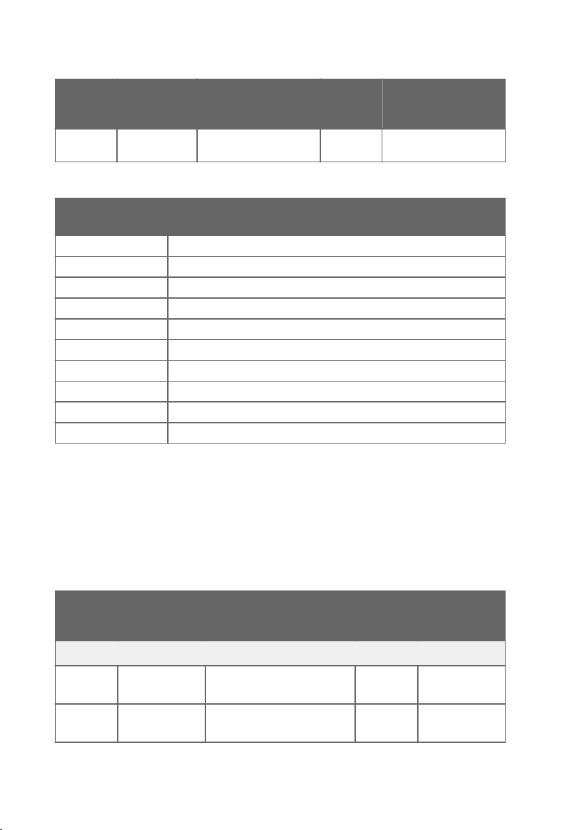
DMT143 User Guide M211435EN-J
Register
Number
(Decimal)
515 0203
Address
(Hexadecimal)
hex
Register Description Data
Format
Error code 32-bit
integer
Notes
0 = No errors
Table 28 Error Codes on Modbus Interface
Error Code Register
Value
Corresponding Error
0 No errors.
1 Temperature measurement error. [44]
2 Humidity measurement error. [45]
64 Device settings corrupted. [50]
128 Additional configuration settings corrupted. [51]
256 Sensor coecients corrupted. [52]
512 Main configuration settings corrupted. [53]
2048 Supply voltage out of range. [55]
65536 Non-volatile memory read/write failure. [57]
131072 Firmware checksum mismatch. [49]
If several errors are active at the same time, the Modbus Error Code register contains the sum
of currently active error codes.
Refer to Error Messages in Insight Software (page 67) for more information about the error
states.
A.4.3 Configuration Registers
Table 29 Modbus Configuration Data Registers (Writable)
Register
Number
(Decimal)
Settings
769 0300
771 0302
78
Address
(Hexadecimal)
hex
hex
Register Description Data
Pressure, power-up default
value
Pressure 32-bit float bar (absolute)
Format
Unit / Valid
Range
32-bit float bar (absolute)
0.001 ... 50
0.001 … 50
Page 81

Appendix A – Modbus Reference
Register
Number
(Decimal)
Settings
Address
(Hexadecimal)
795 031A
Communication
1537 0600
1538 0601
1539 0602
1540 0603
1541 0604
1542 0605
LED Alarm
3073 0C00
3074 0C01
3075 0C02
Factory Settings
7681 1E00
hex
hex
hex
hex
hex
hex
hex
hex
hex
hex
hex
Register Description Data
Format
Unit / Valid
Range
Filtering factor 32-bit float 0.00001 … 1
Address 16-bit
1 ... 247
integer
Bit rate (b/s) 16-bit
integer
Parity, data, stop bits 16-bit
integer
5 = 9600
6 = 19200
0 = N81
1 = N82
2 = E81
3 = E82
4 = O81
5 = O82
Response delay 16-bit
0 ... 1020 ms
integer
Interface mode 16-bit
6 = MODBUS
integer
Restart device 16-bit
integer
Indicator mode 16-bit
integer
1 = Restart the
device
0 = O
1 = Status only
2 = Alarm
Alarm parameter 16-bit
integer
6 = T
d/f
Alarm setpoint 32-bit float -70 °C ... +60 °C
Restore settings 16-bit
integer
1 = Restore
factory settings
79
Page 82
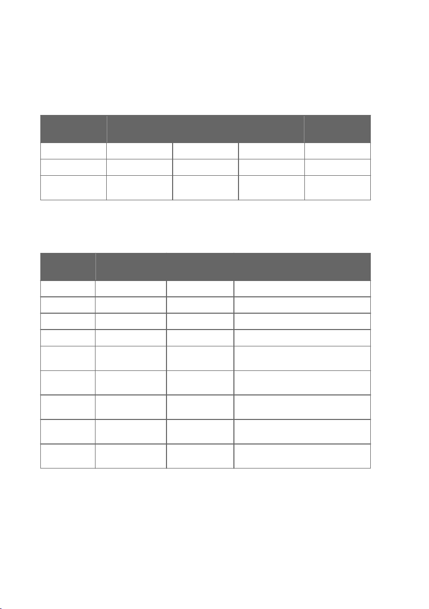
DMT143 User Guide M211435EN-J
A.4.4 Test Value Registers
Read the known test values from the test registers to verify the functionality of your Modbus
implementation.
Table 30 Modbus Test Registers (Read-Only)
Register Number
(Decimal)
7937 1F00
7938 1F01
7940 1F03
Address
(Hexadecimal)
hex
hex
hex
Register
Description
Signed integer 16-bit integer -12345
Floating point 32-bit float -123.45
Text string 7-character ASCII
A.4.5 Device Identification Objects
Table 31 Device Identification Objects
Object Id
(Decimal)
0 00
1 01
2 02
3 03
4 04
5 05
128 80
129 81
130 82
Object Id
(Hexadecimal)
hex
hex
hex
hex
hex
hex
hex
hex
hex
Object Name Example Contents
VendorName “Vaisala”
ProductCode DMT143
MajorMinorVersion Software version (for example “1.4.2”)
VendorUrl “http://www.vaisala.com/”
ProductName Vaisala DRYCAPâ Dewpoint
ModelName Configuration code (for example
SerialNumber
CalibrationDate
CalibrationText
Data Format Value
"-123.45"
string
Transmitter DMT143
"G1A1A1A0A0ASX")
1)
Serial number of the device (for
example “J1140501")
1)
Main calibration date in YYYY-MM-DD
format. Empty string if not set/valid.
1)
Main calibration information text.
Empty string if not set/valid.
1) Vaisala-specific device identification object.
80
Page 83
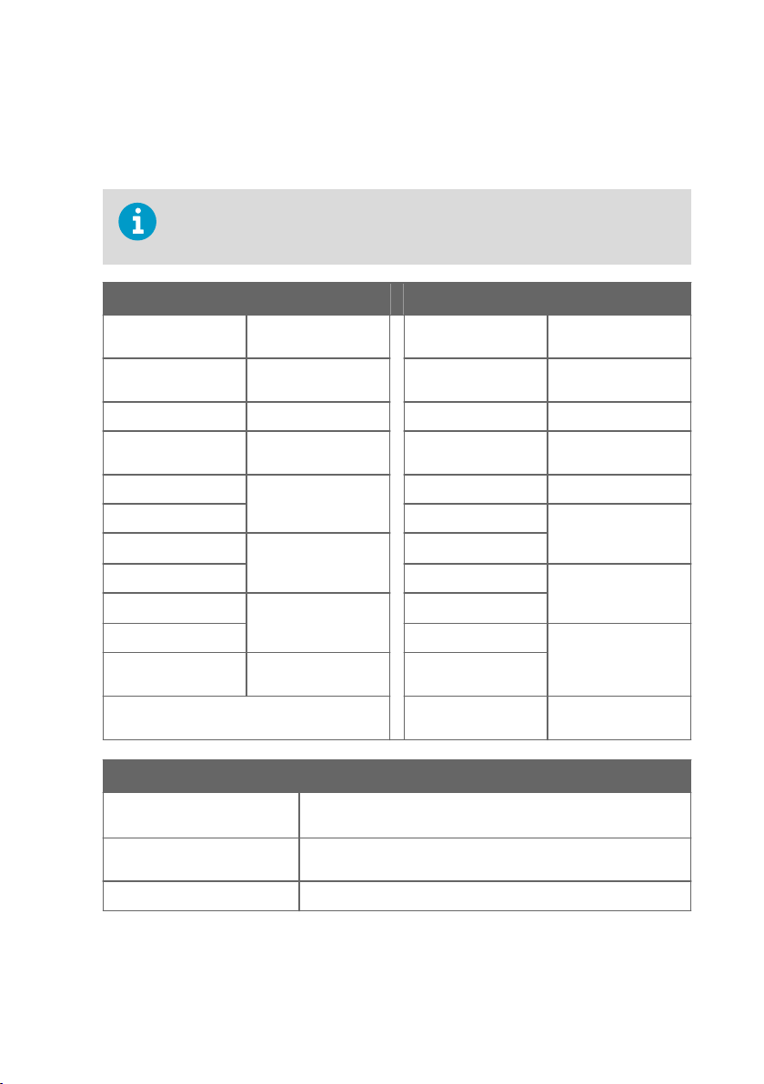
Appendix A – Modbus Reference
A.5 Modbus Communication Examples
Reading Dew Point/Frost Point Temperature Value
Device address used in the following examples is 240 (F0
hex
).
The values returned by the device dier depending on the ambient conditions
and/or device settings. Your device might not return exactly the same values.
Request Response
Bytes on the Line
(Hexadecimal)
(silence for 3.5 bytes) Start of Modbus RTU
F0
hex
03
hex
00
hex
06
hex
00
hex
02
hex
31
hex
2B
hex
(silence for 3.5 bytes) End of Modbus RTU
Description Bytes on the Line
(Hexadecimal)
(silence for 3.5 bytes) Start of Modbus RTU
frame
Transmitter address F0
Function (Read
Holding Registers)
Register address 04
Number of 16-bit
registers to read (2)
Modbus RTU
checksum
frame
03
F5
96
C0
E7
D9
56
hex
hex
hex
hex
hex
hex
hex
hex
hex
Description
frame
Transmitter address
Function (Read
Holding Registers)
Number of data bytes
Value of first register
(least significant
word)
Value of second
register (most
significant word)
Modbus RTU
checksum
(silence for 3.5 bytes) End of Modbus RTU
frame
Communication Description
Register number 7 (1-based Modbus register number) = address 0006
(0-based
hex
address used in actual communication).
Data format Two 16-bit Modbus registers interpreted as IEEE 754 binary32
floating point value, least significant word first.
Returned value C0E7F596
, which is binary32 representation of -7.25 (°C).
hex
81
Page 84
DMT143 User Guide M211435EN-J
Writing Filtering Factor Value
Request Response
Bytes on the Line
(Hexadecimal)
(silence for 3.5 bytes) Start of Modbus RTU
F0
hex
10
hex
03
hex
1A
hex
00
hex
02
hex
04
hex
CC
hex
CD
hex
3E
hex
4C
hex
DE
hex
E9
hex
(silence for 3.5 bytes) End of Modbus RTU
Description Bytes on the Line
(Hexadecimal)
(silence for 3.5 bytes) Start of Modbus RTU
frame
Transmitter address F0
Function (Write
Multiple Registers)
Register address 03
Number of registers to
write (2)
Number of data bytes 75
Value for the first
register (least
significant word)
Value for the second
register (most
significant word)
Modbus RTU
checksum
hex
10
hex
hex
1A
hex
00
hex
02
hex
hex
6A
hex
(silence for 3.5 bytes) End of Modbus RTU
The response to a write
function informs that the
function was correctly received
by the device. It does not
guarantee that the written
value was accepted by the
device (for example, in case of
frame
out-of-range values).
To verify that the value was
really accepted by the device,
read the register value after
writing.
Description
frame
Transmitter address
Function (Write
Multiple Registers)
Register address
Number of 16-bit
registers written (2)
Modbus RTU
checksum
frame
Communication Description
Register number 795 (1-based Modbus register number) = address 031A
hex
based address used in actual communication).
Data format Two 16-bit Modbus registers interpreted as IEEE 754 binary32
floating point value, least significant word first.
Value to write 0.2, in binary32 format 3E4CCCCD
hex
.
82
(0-
Page 85

Appendix A – Modbus Reference
83
Page 86

DMT143 User Guide M211435EN-J
84
Page 87

Warranty
For standard warranty terms and conditions, see www.vaisala.com/warranty.
Please observe that any such warranty may not be valid in case of damage due to normal wear
and tear, exceptional operating conditions, negligent handling or installation, or unauthorized
modifications. Please see the applicable supply contract or Conditions of Sale for details of the
warranty for each product.
Technical Support
Contact Vaisala technical support at [email protected]. Provide at least the
following supporting information:
• Product name, model, and serial number
• Name and location of the installation site
• Name and contact information of a technical person who can provide further
information on the problem
For more information, see www.vaisala.com/support.
Recycling
Recycle all applicable material.
Follow the statutory regulations for disposing of the product and packaging.
85
Page 88

DMT143 User Guide M211435EN-J
86
Page 89

Page 90

www.vaisala.com
 Loading...