

Page 1

r
USER'S GUIDE
Vaisala DRYCAP® Dewpoint
Transmitte
DMT142
M210397EN-D
Page 2

PUBLISHED BY
Vaisala Oyj Phone (int.): +358 9 8949 1
P.O. Box 26 Fax: +358 9 8949 2227
FIN-00421 Helsinki
Finland
Visit our Internet pages at http://www.vaisala.com/
© Vaisala 2006
No part of this manual may be reproduced in any form or by any means, electronic or
mechanical (including photocopying), nor may its contents be communicated to a third
party without prior written permission of the copyright holder.
The contents are subject to change without prior notice.
Please observe that this manual does not create any legally binding obligations for
Vaisala towards the customer or end user. All legally binding commitments and
agreements are included exclusively in the applicable supply contract or Conditions of
Sale.
Page 3

_________________________________________________________________________________
Table of Contents
CHAPTER 1
GENERAL INFORMATION ............................................................................ 5
About This Manual ................................................................... 5
Contents of This Manual ....................................................... 5
Version Information ............................................................... 6
Related Manuals ................................................................... 6
General Safety Considerations ............................................. 7
Feedback............................................................................... 7
Product Related Safety Precautions ...................................... 7
Recycling .................................................................................. 8
Regulatory Compliances ......................................................... 8
Electromagnetic Compatibility ............................................... 8
Trademarks ............................................................................... 8
Warranty .................................................................................... 9
CHAPTER 2
PRODUCT OVERVIEW .................................................................................. 3
Introduction to Dewpoint Transmitter DMT142 ..................... 3
The Basic Features and Options ............................................ 3
CHAPTER 3
FUNCTIONAL DESCRIPTION ....................................................................... 5
Advanced DRYCAP® Technology ........................................... 5
Auto-Calibration .................................................................... 5
Sensor Purge ........................................................................6
Sensor Warming in High Humidities ..................................... 6
CHAPTER 4
INSTALLATION.............................................................................................. 7
Selecting Location ................................................................... 7
Wiring ........................................................................................9
Optional Connection Cable ................................................. 10
Power Supply Requirements............................................... 11
Mounting .................................................................................13
Direct Measurement in Process Pipeline ............................ 13
Sampling from Pressurized Processes ............................... 14
DMT242SC Sampling Cell ............................................. 14
DMT242SC2 Sampling Cell with Swagelok
Connectors.....................................................................
DSC74 Sampling Cell with Quick Connector and Leak
Screw .............................................................................
DSC74B Two-Pressure Sampling Cell .......................... 17
DSC74C Two-Pressure Sampling Cell with Coil ........... 18
DM240FA Duct Installation Flange ................................ 20
15
15
VAISALA_________________________________________________________________________ 1
Page 4

User's Guide _______________________________________________________________________
CHAPTER 5
SERIAL COMMANDS ..................................................................................21
Connecting Serial Interface ...................................................21
Commands for Basic Settings ..............................................22
Select Nonmetric Unit .......................................................... 22
Select Metric Unit ................................................................22
Scale Dewpoint Analog Output ...........................................22
Select Analog Output Quantity ............................................22
Set Analog Output Mode ..................................................... 23
DMT142 Firmware Version Output......................................23
Pressure Compensation ......................................................24
Test Analog Output Current ................................................ 25
Test Analog Voltage Output ................................................25
Restart Program ..................................................................25
Serial Line Output Commands ..............................................26
Start Measurement Output .................................................. 26
Stop Measurement Output ..................................................26
Set Output Interval............................................................... 26
Polling Mode for DMT142 Transmitter.................................. 27
Set Transmitter Address ...................................................... 27
Set Serial Interface Mode ....................................................27
OPEN Opening the Transmitter in POLL-State................... 28
SEND Outputting a Reading Once...................................... 28
CHAPTER 6
MAINTENANCE............................................................................................29
Calibration and Adjustment...................................................29
Filter Change...........................................................................29
Vaisala Service Centers .........................................................30
CHAPTER 7
TROUBLESHOOTING..................................................................................31
Error States ............................................................................. 31
Technical Support ..................................................................31
CHAPTER 8
TECHNICAL DATA ......................................................................................33
Specifications .........................................................................33
Spare Parts and Accessories ................................................ 36
Dimensions in mm (inches)................................................... 37
Wiring Quick Reference .........................................................37
2 ____________________________________________________________________ M210397EN-D
Page 5

_________________________________________________________________________________
List of Figures
Figure 1 Dewpoint Transmitter DMT142 Components............................. 4
Figure 2 Mounting Dewpoint Transmitter DMT142 .................................. 8
Figure 3 Wiring of Voltage Output Version............................................... 9
Figure 4 Wiring of Current Output Version ............................................... 9
Figure 5 Pin Order of DMT142 Connector (Transmitter Side) ............... 10
Figure 6 Snap-On Type Cable................................................................ 11
Figure 7 Screw Fitting Type Cable ......................................................... 11
Figure 8 Example Of Sensor Purge Current (at Room Temperature with
24 VDC)....................................................................................
Figure 9 Example of Auto-Calibration Current (at Room Temperature
with 24 VDC) ............................................................................
Figure 10 DMT142 Installed Directly to Pipeline ...................................... 13
Figure 11 DMT242SC Sampling Cell ....................................................... 14
Figure 12 DMT242SC2 Sampling Cell with Swagelok Connectors.......... 15
Figure 13 DSC74 Sampling Cell with Accessories................................... 16
Figure 14 DSC74B.................................................................................... 17
Figure 15 Removing the Leak Screw ....................................................... 17
Figure 16 Default Assembly of DSC74C .................................................. 18
Figure 17 Alternative Assembly of DSC74C (for Tight Spaces)............... 19
Figure 18 DM240FA with DMT142 ........................................................... 20
Figure 19 DMT142 Dewpoint Measurement Accuracy Graph ................. 34
Figure 20 DMT142 Dimensions ................................................................ 37
12
12
List of Tables
Table 1 Manual Revisions ....................................................................... 6
Table 2 Related Manuals ........................................................................ 6
Table 3 Wiring Table ............................................................................... 9
Table 4 Description of DMT142 Connection Cable............................... 10
Table 5 DMT142 Serial Interface Setting .............................................. 21
Table 6 Pressure Conversion Coefficients............................................ 24
Table 7 Measured Variable ...................................................................33
Table 8 Operating Environment Specifications ..................................... 34
Table 9 Output Specifications ............................................................... 34
Table 10 General Specifications ............................................................. 35
VAISALA_________________________________________________________________________ 3
Page 6

User's Guide _______________________________________________________________________
This page intentionally left blank.
4 ____________________________________________________________________ M210397EN-D
Page 7

Chapter 1 _________________________________________________________ General Information
CHAPTER 1
GENERAL INFORMATION
This chapter provides general notes for the manual and the product.
About This Manual
This manual provides information for installing, operating, and
maintaining Dewpoint Transmitter DMT142.
Contents of This Manual
This manual consists of the following chapters:
- Chapter 1, General Information, provides general notes for the
manual and the product.
- Chapter 2, Product Overview, introduces the features and
advantages of Dewpoint Transmitter DMT142.
- Chapter 3, Functional Description, describes the advanced
functionality of Dewpoint Transmitter DMT142, including the
auto-calibration, sensor purge and sensor warming functions.
- Chapter 4, Installation, provides you with information that is
intended to help you install Dewpoint Transmitter DMT142.
VAISALA_________________________________________________________________________ 5
Page 8

User's Guide _______________________________________________________________________
- Chapter 5, Serial Commands, contains the operating instructions
for the serial interface of Dewpoint Transmitter DMT142.
- Chapter 6, Maintenance, provides information that is needed in
basic maintenance of Dewpoint Transmitter DMT142, and contact
information for Vaisala Service Centers.
- Chapter 7, Troubleshooting, describes the error states and provides
contact information for technical support.
- Chapter 8, Technical Data, provides the technical data of Dewpoint
Transmitter DMT142.
Version Information
Table 1 Manual Revisions
Manual Code Description
M210397EN-A Vaisala DRYCAP® Dewpoint
Transmitter DMT142 Advanced User
Manual, April 2003
M210397EN-B Vaisala DRYCAP® Dewpoint
Transmitter DMT142 User's Guide,
October 2005
Td measurement and operating
pressure range specification revised
New sampling cell, installation flange
and connection cable options added
M210397EN-C Vaisala DRYCAP® Dewpoint
Transmitter DMT142 User's Guide,
March 2006; this manual
Corrected wiring diagrams
Related Manuals
Table 2 Related Manuals
Manual Code Manual Name
M210396EN-A Vaisala DRYCAP® Dewpoint
Transmitter DMT142 Quick
Reference Guide
6 ____________________________________________________________________ M210397EN-D
Page 9

Chapter 1 _________________________________________________________ General Information
General Safety Considerations
Throughout the manual, important safety considerations are
highlighted as follows:
WARNING
CAUTION
NOTE
Warning alerts you to a serious hazard. If you do not read and follow
instructions very carefully at this point, there is a risk of injury or
even death.
Caution warns you of a potential hazard. If you do not read and
follow instructions carefully at this point, the product could be
damaged or important data could be lost.
Note highlights important information on using the product.
Feedback
Vaisala Customer Documentation Team welcomes your comments
and suggestions on the quality and usefulness of this publication. If
you find errors or have other suggestions for improvement, please
indicate the chapter, section, and page number. You can send
comments to us by e-mail: manuals@vaisala.com
Product Related Safety Precautions
The Dewpoint Transmitter DMT142 delivered to you has been tested
for safety and approved as shipped from the factory. Note the
following precautions:
CAUTION
VAISALA_________________________________________________________________________ 7
Do not modify the unit. Improper modification can damage the
product or lead to malfunction.
Page 10

User's Guide _______________________________________________________________________
Recycling
Recycle all applicable material.
Dispose of batteries and the unit according to statutory regulations.
Do not dispose of with regular household refuse.
Regulatory Compliances
Vaisala DRYCAP® Dewpoint Transmitter DMT142 complies with
the following performance and environmental test standards:
Trademarks
Electromagnetic Compatibility
EN 61326-1:1997 + Am1:1998, Electrical equipment for
measurement, control and laboratory use - EMC requirements Industrial environment.
[CISPR16/22 Class B, EN/IEC 61000-4-2, EN/IEC 61000-4-3,
EN/IEC 61000-4-4, EN/IEC 61000-4-5, EN/IEC 61000-4-6]
DRYCAP® is a registered trademark of Vaisala.
8 ____________________________________________________________________ M210397EN-D
Page 11

Chapter 1 _________________________________________________________ General Information
Warranty
Vaisala hereby represents and warrants all Products
manufactured by Vaisala and sold hereunder to be
free from defects in workmanship or material
during a period of twelve (12) months from the date
of delivery save for products for which a special
warranty is given. If any Product proves however to
be defective in workmanship or material within the
period herein provided Vaisala undertakes to the
exclusion of any other remedy to repair or at its
own option replace the defective Product or part
thereof free of charge and otherwise on the same
conditions as for the original Product or part
without extension to original warranty time.
Defective parts replaced in accordance with this
clause shall be placed at the disposal of Vaisala.
Vaisala also warrants the quality of all repair and
service works performed by its employees to
products sold by it. In case the repair or service
works should appear inadequate or faulty and
should this cause malfunction or nonfunction of the
product to which the service was performed Vaisala
shall at its free option either repair or have repaired
or replace the product in question. The working
hours used by employees of Vaisala for such repair
or replacement shall be free of charge to the client.
This service warranty shall be valid for a period of
six (6) months from the date the service measures
were completed.
This warranty does not however apply when the
defect has been caused through
a) normal wear and tear or accident;
b) misuse or other unsuitable or unauthorized use
of the Product or negligence or error in storing,
maintaining or in handling the Product or any
equipment thereof;
c) wrong installation or assembly or failure to
service the Product or otherwise follow
Vaisala's service instructions including any
repairs or installation or assembly or service
made by unauthorized personnel not approved
by Vaisala or replacements with parts not
manufactured or supplied by Vaisala;
d) modifications or changes of the Product as well
as any adding to it without Vaisala's prior
authorization;
e) other factors depending on the Customer or a
third party.
Notwithstanding the aforesaid Vaisala's liability
under this clause shall not apply to any defects
arising out of materials, designs or instructions
provided by the Customer.
This warranty is however subject to following
conditions:
a) A substantiated written claim as to any alleged
defects shall have been received by Vaisala
within thirty (30) days after the defect or fault
became known or occurred, and
b) The allegedly defective Product or part shall,
should Vaisala so require, be sent to the works
of Vaisala or to such other place as Vaisala may
indicate in writing, freight and insurance
prepaid and properly packed and labelled,
unless Vaisala agrees to inspect and repair the
Product or replace it on site.
This warranty is expressly in lieu of and excludes
all other conditions, warranties and liabilities,
express or implied, whether under law, statute or
otherwise, including without limitation any implied
warranties of merchantability or fitness for a
particular purpose and all other obligations and
liabilities of Vaisala or its representatives with
respect to any defect or deficiency applicable to or
resulting directly or indirectly from the Products
supplied hereunder, which obligations and
liabilities are hereby expressly cancelled and
waived. Vaisala's liability shall under no
circumstances exceed the invoice price of any
Product for which a warranty claim is made, nor
shall Vaisala in any circumstances be liable for lost
profits or other consequential loss whether direct or
indirect or for special damages.
VAISALA_________________________________________________________________________ 9
Page 12

User's Guide _______________________________________________________________________
This page intentionally left blank.
2 ____________________________________________________________________ M210397EN-D
Page 13

Chapter 2 ___________________________________________________________ Product Overview
CHAPTER 2
PRODUCT OVERVIEW
This chapter introduces the features and advantages of Dewpoint
Transmitter DMT142.
Introduction to Dewpoint Transmitter DMT142
Vaisala DRYCAP® dewpoint transmitter DMT142 is designed for a
wide range of OEM applications. The excellent stability and reliability
of its performance is based on advanced DRYCAP® polymer sensor
technology. The DRYCAP® technology has low maintenance needs
due to its excellent long term stability and durability against
condensation. The DMT142 transmitter is easy to install and the
mechanics have been designed for harsh environments requiring
protection against dust, dirt and splashed water.
The Basic Features and Options
- Small size to fit in tight installations.
- Analog outputs: 4 ... 20 mA or 0 - 1 V/0 - 5 V versions.
- Low maintenance requirements due to excellent long term stability.
- DRYCAP® polymer sensor with automatic auto-calibration and
sensor purge ensures long term stability.
- Sensor warming keeps the sensor dry in abnormally high humidity
situations.
- Field check suitability with DM70 hand-held meter.
VAISALA_________________________________________________________________________ 3
Page 14
User's Guide _______________________________________________________________________
- RS232 serial line connection for service use with DMT142RS
cable.
- Optional sampling cells with different installation options available
as DMT142 installation accessories.
3
4
2
1
5
678
0507-093
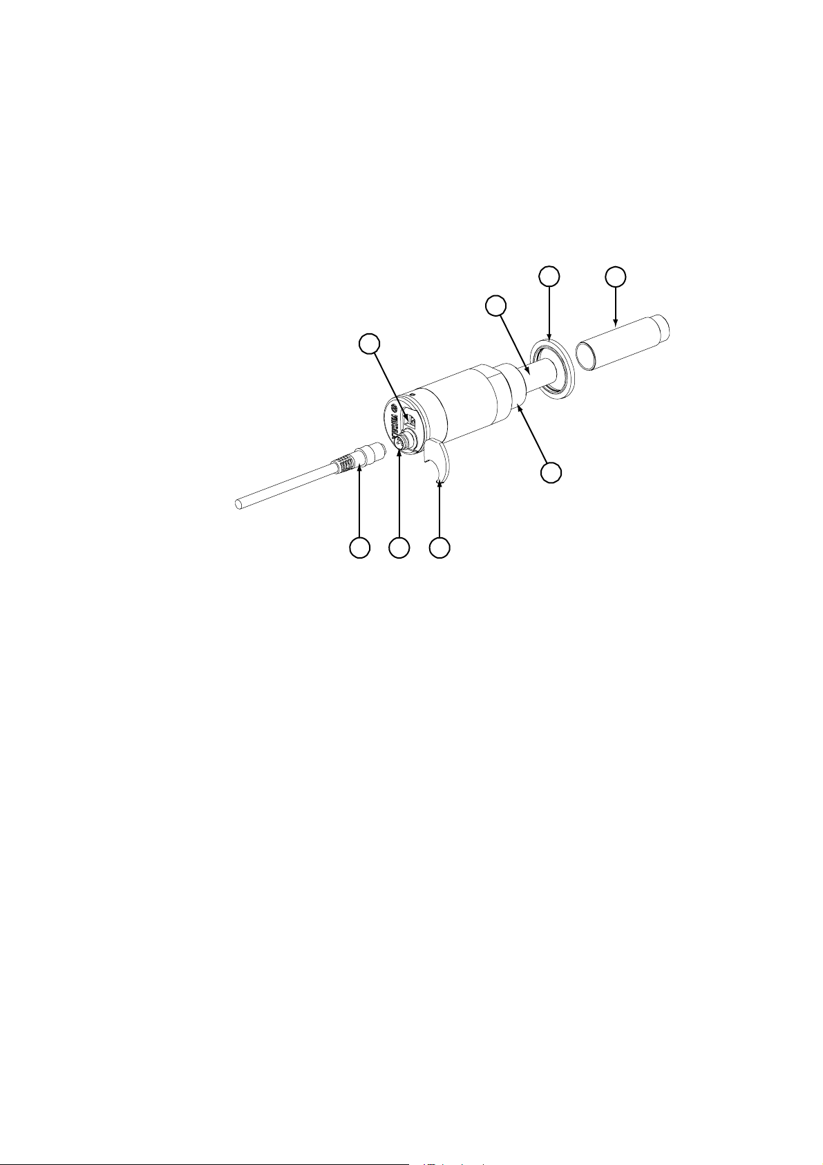
Figure 1 Dewpoint Transmitter DMT142 Components
The following numbers refer to Figure 1 above:
1 = Serial line connector (for service use)
2 = DRYCAP® sensor protected with sintered filter
3 = Sealing washer
4 = Protective cap for probe
5 = G1/2" ISO 228/1
6 = Protection plug for serial line connector
7 = Cable connector
8 = Connection cable (optional)
4 ____________________________________________________________________ M210397EN-D
Page 15

Chapter 3 _______________________________________________________ Functional Description
CHAPTER 3
FUNCTIONAL DESCRIPTION
This chapter describes the advanced functionality of Dewpoint
Transmitter DMT142, including the auto-calibration, sensor purge and
sensor warming functions.
Advanced DRYCAP® Technology
Dewpoint Transmitter DMT142 utilizes an advanced, patented
measurement technology to ensure accurate measurement with
excellent long term stability. This results in very low maintenance
requirements for the transmitter. The lasting performance is achieved
with microprocessor technology and software that automatically
performs self-diagnostic functions in addition to the normal dewpoint
measurement. The self-diagnostic procedures that are conducted are
called auto-calibration, sensor purge and sensor warming.
Auto-Calibration
The auto-calibration feature of the DMT142 transmitter is an
automatic procedure which greatly reduces the possible drift in the dry
end of the dewpoint measurement. It is performed at one hour
intervals, and when the power is switched on. During auto-calibration
the sensor is warmed for a short period (< 1 min) and the sensor
capacitance values are evaluated at the elevated temperature. The
possible dry end drift is then corrected to correspond to the calibrated
values. During the auto-calibration the transmitter outputs the Td value
prior to the procedure.
VAISALA_________________________________________________________________________ 5
Page 16

User's Guide _______________________________________________________________________
Auto-calibration is carried out only if several criteria for the
measurement environment are fulfilled. This ensures the reliability of
the adjustments, and maintains the excellent long term stability that
the patented technology offers. These criteria include for example a
stable enough moisture level in the measured atmosphere. If the
conditions are not fulfilled, the auto-calibration function is postponed
until satisfactory conditions are reached.
Sensor Purge
Sensor purge is also an automatic procedure that minimizes the drift at
the wet end readings of the dewpoint measurement. Sensor purge is
performed once a day or when the power is switched on. The sensor is
heated for several minutes which will then evaporate all excess
molecules out of the sensor polymer. This, together with the autocalibration results in a very small drift of the sensor due to the very
linear behaviour of the polymer technology.
Sensor Warming in High Humidities
Additionally the DMT142 transmitter has a warming feature which
prevents the sensor and filter from becoming wet in high humidities.
High humidity may be present when the dewpoint temperature rises
close to the gas temperature.
Sensor warming is switched on automatically when the humidity in
the measured gas increases to a level where dew can start to form. The
advantage of sensor warming is the rapid response of dewpoint
measurement. A wet sensor and filter would otherwise result in a
dewpoint equal to ambient temperature (that is RH = 100 %).
If in spite of sensor warming the sensor gets soaked, it will recover
fully back to normal operation after it dries out.
6 ____________________________________________________________________ M210397EN-D
Page 17

Chapter 4 ________________________________________________________________ Installation
CHAPTER 4
INSTALLATION
This chapter provides you with information that is intended to help
you install Dewpoint Transmitter DMT142.
Selecting Location
In the mounting of Dewpoint Transmitter DMT142 it is important that
the point of installation represents well the gas to be measured.
Temperature changes do not affect the dewpoint measurement, but
pressure changes will have an effect on the measurement. All leaks in
the system must be eliminated to avoid ambient humidity affecting the
measurement.
VAISALA_________________________________________________________________________ 7
Page 18

User's Guide _______________________________________________________________________
0507-094
Figure 2 Mounting Dewpoint Transmitter DMT142
The numbers in the following list refer to Figure 2 above:
1. Select a proper location to mount the DMT142 and remove the
yellow sensor protective cap.
2. Fit the sealing washer onto the probe.
3. Mount the transmitter to the measurement point. The transmitter
has parallel thread G1/2" ISO 228/1.
4. Connect the wires of the connection cable. When using the cable
provided with DMT142 refer to the following wiring section.
See the power supply requirements on page 11.
5. Plug in the cable to the transmitter and turn on the power supply.
6. Self diagnostics performed at start-up freeze the output during
the first minutes of operation. Typical warm-up time is about 5
minutes before normal operation.
8 ____________________________________________________________________ M210397EN-D
Page 19

Chapter 4 ________________________________________________________________ Installation
Wiring
Table 3 Wiring Table
Pin Number Wire Colour
(in supplied cables
EN50044)
1 Brown + VDC supply voltage
2 White - analog output signal
3 Blue - VDC supply voltage
4 Black + analog output signal
1
Name
sense
(voltage output versions
only)
4
+
2
3
0507-095
-
+
12-28VV
-
Figure 3 Wiring of Voltage Output Version
The numbers below refer to Figure 3 above:
1 = Brown
2 = White
3 = Blue
4 = Black
1
4
+
2
3
mA
-
+
18-28V
-
0507-096
Figure 4 Wiring of Current Output Version
Note the three wire connection. The numbers below refer to Figure 4
above:
1 = Brown
2 = White
3 = Blue
4 = Black
VAISALA_________________________________________________________________________ 9
Page 20

User's Guide _______________________________________________________________________
3
1
24
0507-097
Figure 5 Pin Order of DMT142 Connector (Transmitter
Side)
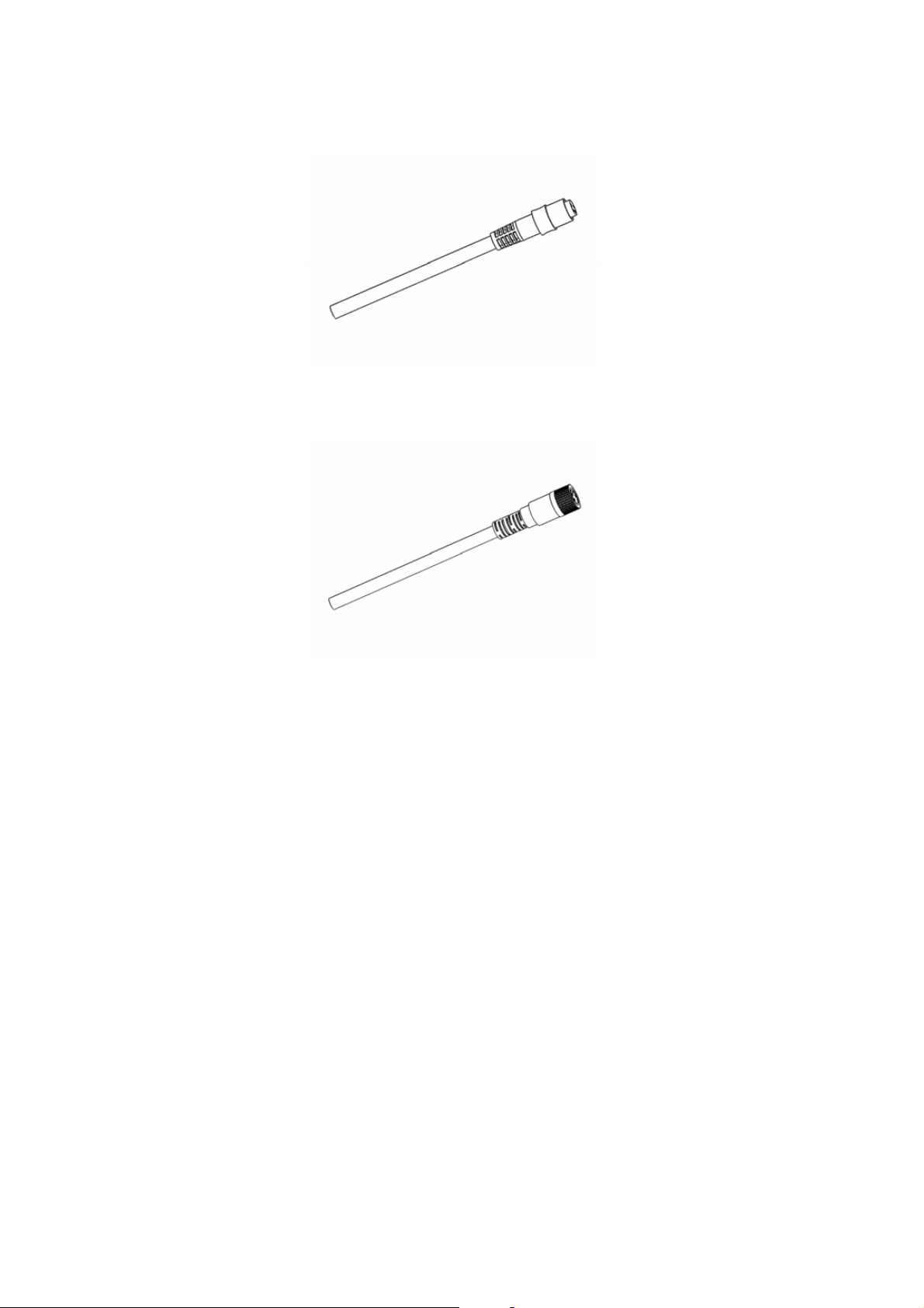
Optional Connection Cable
DMT142 is delivered optionally with two types of connection cables,
snap-on type or with screw fitting/locking.
Table 4 Description of DMT142 Connection Cable
Property Description / Value
M8 Female, straight connector, molded sensor cable, IEC 60947-5-2
Color Black
Number of contacts 4
Conductors 0.25 mm² (× 4) /
0.00039 inch² (× 4)
Insulation PVC
Cable diameter 5.0 mm / 0.2 inch
Protection class IP67 / NEMA 4
Wire color code EN50044
Snap-on type
Cable length 2 m / 6.6 ft
Screw fitting type
Shielded cable
0.3 m / 1 ft
3 m / 9.8 ft
5 m / 16.4 ft
10 m / 32.8 ft
10 ___________________________________________________________________ M210397EN-D
Page 21
Chapter 4 ________________________________________________________________ Installation
0510-036
Figure 6 Snap-On Type Cable
0510-037
Figure 7 Screw Fitting Type Cable
Power Supply Requirements
The DMT142 transmitters are designed to operate with a supply
voltage of 12 ... 28 VDC (voltage output version) or 18 ... 28 VDC
(current output version).
When measuring in pressures 20 ... 50 bar
temperatures -40 ... 0 °C (-40 ... 32 °F), a supply voltage of
24 ... 28 VDC is required.
The power supply should maintain the voltage for all load conditions.
Current consumption during normal operation is 10 mA. The
consumption increases during the sensor self-diagnostics (autocalibration and sensor purge). The maximum current consumption is
220 mA pulsed current (see the pictures
(290 ... 725 psia) or
a
on page 4).
VAISALA________________________________________________________________________ 11
Page 22

User's Guide _______________________________________________________________________
150 mA
500 ms/div
0507-098. 0507-099
Figure 8 Example Of Sensor Purge Current (at Room
Duration 60 seconds
Temperature with 24 VDC)
↓
Typical duty cycle. Sensor purge current varies with supply voltage
and operating temperature. The peak value is the highest in the lowest
temperature.
150 mA
100 ms/div
0507-100, 0507-101
Figure 9 Example of Auto-Calibration Current (at Room
Duration ~30 seconds
Temperature with 24 VDC)
↓
Typical duty cycle. Auto-calibration current varies with supply
voltage and operating temperature.
12 ___________________________________________________________________ M210397EN-D
Page 23

Chapter 4 ________________________________________________________________ Installation
Mounting
The recommended installation is directly to the measured gas pipeline,
chamber etc. If the gas temperature is higher than the specified
maximum operating temperature of the transmitter, gas sampling and
cooling it to ambient temperature is recommended. Note that the
dewpoint temperature must be clearly lower than the ambient
temperature to avoid condensation in the sampling line. Sampling
from the process is easy by using Vaisala sampling cell options.
Direct Measurement in Process Pipeline
Direct installation to the measured gas is the recommended
installation method if the temperature of the gas is suitable for
DMT142 and no additional filtering is needed due to very dusty or
oily gas. Oil as such is not harmful for the DRYCAP
response time may be slowed down if the sintered filter becomes
clogged up with oil. The maximum measurement pressure is
50 bara / 725 psia (absolute pressure) for direct measurement.
®
sensor, but
Max 50 bar
0507-102
Figure 10 DMT142 Installed Directly to Pipeline
In addition, due to the small size of DMT142 you can use a standard
G1/2" T-shaped pipe fitting (not available from Vaisala) when
installing DMT142 into a pipeline.
VAISALA________________________________________________________________________ 13
Page 24

User's Guide _______________________________________________________________________
Sampling from Pressurized Processes
The maximum measurement pressure is 50 bara / 725 psia (absolute
pressure) for sampling cell use. Pressure change between the process
and sampling point will change the dewpoint temperature resulting in
incorrect dewpoint reading. When sampling pressurized processes
above 50 bar, the pressure must be regulated to 50 bar or below and
the effect of the pressure difference between the process and the
measurement cell must be taken into account in calculating the
dewpoint.
The dewpoint measurement with the DRYCAP® sensor is not flow
sensitive but the flow rate affects the response time. The optimal flow
rate depends of the application but a minimum flow rate of 0.2 l/min is
recommended.
The DMT142 is very light in weight which means that it can be
installed in a sample pipeline in the sampling cells without the need of
any additional mechanical support.
Five different sampling cell options and an installation flange are
available.
DMT242SC Sampling Cell
0507-103
Figure 11 DMT242SC Sampling Cell
The following numebrs refer to Figure 11 above:
1 = G1/4"
2 = G3/8"
DMT242SC is the basic sample cell with G3/8" ISO gas inlet thread
and G1/4" ISO gas outlet thread.
14 ___________________________________________________________________ M210397EN-D
Page 25

Chapter 4 ________________________________________________________________ Installation
DMT242SC2 Sampling Cell with Swagelok Connectors
DMT242SC2 is mechanically similar to DMT242SC but has welded
Swagelok connectors for 1/4" tubing/pipeline. Welded connectors
eliminate the possibility of leakage in the connectors.
0507-104
Figure 12 DMT242SC2 Sampling Cell with Swagelok
Connectors
The following number refers to Figure 12 above:
1 = Swagelok 1/4" connectors
DSC74 Sampling Cell with Quick Connector and Leak Screw
Vaisala DSC74 sampling cell allows quick and easy connection of the
transmitter into pressurized processes. The quick connector allows the
transmitter to be plugged in to the pipeline in seconds. The leak screw
maintains the process pressure in the sampling cell but allows a small
flow through the sampling cell. The DSC74 includes the following
parts:
- DMT242SC sampling cell
- adjustable leak screw, thread 3/8"G
- quick connector (type D, NIP08, Quick 08)
- thread adapter, type male- male 3/8"G-1/2"G
- thread adapter, type male-female 3/8"G-1/4"G
VAISALA________________________________________________________________________ 15
Page 26

User's Guide _______________________________________________________________________
0507-105
Figure 13 DSC74 Sampling Cell with Accessories
The following numbers refer to Figure 13 above:
1 = Thread adapter type 3/8"G-1/2"G
2 = Thread adapter type 3/8"G-1/4"G
3 = Quick connector
4 = Leak screw
5 = Sampling cell DMT242SC
When using the DSC74, seal the threads of the quick connector or
thread adapter carefully with PTFE thread seal tape. Tighten with a
fork spanner. Ensure that the leaking screw of the sampling cell is
open but not too much as to cause a pressure drop inside the sampling
cell. Close the screw fully first, then turn 1/2 turn to open it.
16 ___________________________________________________________________ M210397EN-D
Page 27
Chapter 4 ________________________________________________________________ Installation
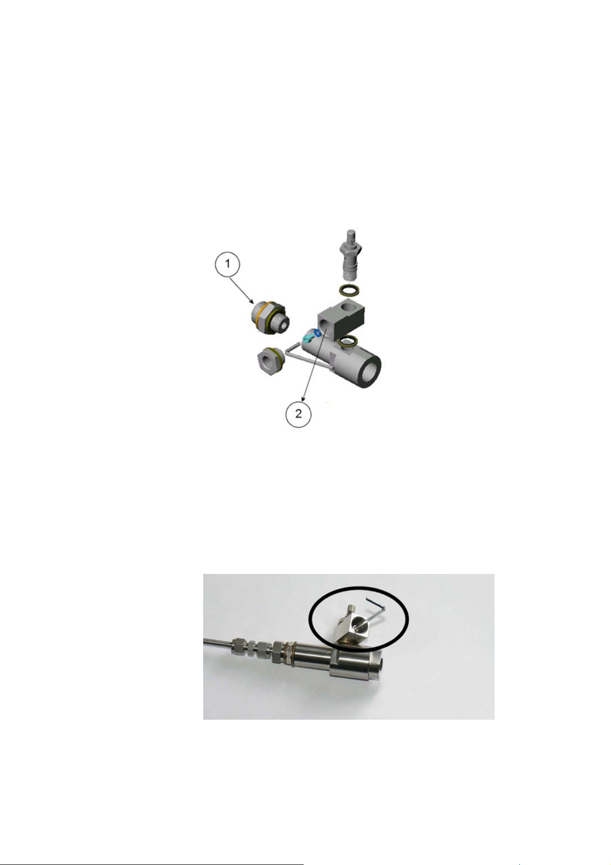
DSC74B Two-Pressure Sampling Cell
The DSC74B can be used as the DSC74 for measurements in process
pressure. DSC74B limits the flow rate with a leak screw. The
maximum flow can also be increased by removing the leak screw and
adjusting the flow manually with the valve. To remove the leak screw,
see Figure 15 below.
0510-032
Figure 14 DSC74B
The following numbers refer to Figure 14 above:
1 = Gas goes in
2 = Gas comes out
0510-033
Figure 15 Removing the Leak Screw
VAISALA________________________________________________________________________ 17
Page 28
User's Guide _______________________________________________________________________
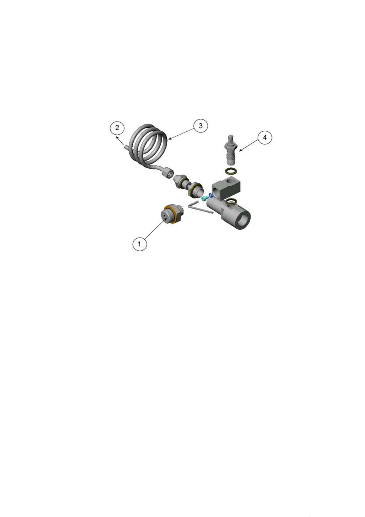
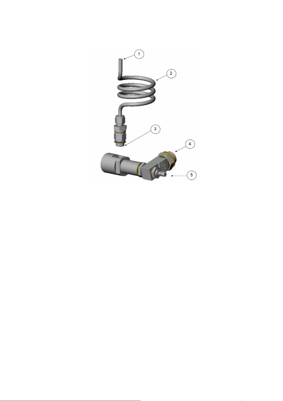
DSC74C Two-Pressure Sampling Cell with Coil
The DSC74C is mechanically like the DSC74B, but it is supplied with
a coil for measurements in atmospheric pressure. The coil can also be
used as a cooling coil for sampling from high temperature processes.
0510-034
Figure 16 Default Assembly of DSC74C
The following numbers refer to Figure 16 above:
1 = Gas goes in. Also the coil can be used here.
2 = Gas comes out
3 = Coil
4 = Valve
18 ___________________________________________________________________ M210397EN-D
Page 29
Chapter 4 ________________________________________________________________ Installation
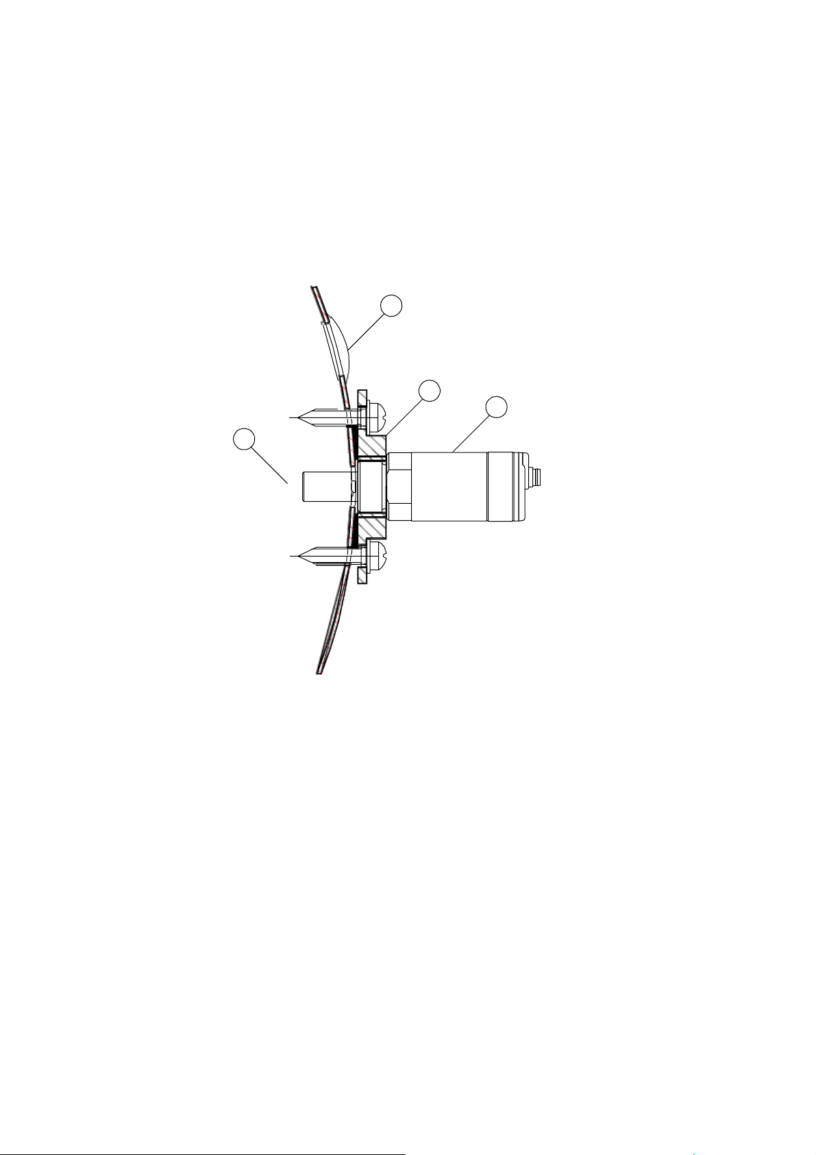
0403-113
Figure 17 Alternative Assembly of DSC74C (for Tight Spaces)
The following numbers refer to Figure 17 above:
1 = Gas comes out
2 = Coil
3 = Thread, max. size 7 mm
4 = Gas goes in
5 = Valve
The thread size cannot exceed 7 mm. Use the provided adapter to
avoid damage to the probe.
VAISALA________________________________________________________________________ 19
Page 30
User's Guide _______________________________________________________________________
DM240FA Duct Installation Flange
The transmitter can be installed directly in the process wall through
DM240FA duct installation flange. When the probe is installed
directly on the process wall or pipe, note that a closing valve may be
needed on both sides of the installed probe so that the sensor head can
be removed from the process for calibration or maintenance.
4
3
2
1
0510-035
Figure 18 DM240FA with DMT142
Numbers refer to Figure 18 above:
1 = Measured gas
2 = DMT142 transmitter
3 = DM240FA flange (thread G1/2" ISO)
4 = Recommended additional hole (plugged) for Td field check
reference measurement probe (for example, Vaisala DM70)
20 ___________________________________________________________________ M210397EN-D
Page 31

Chapter 5 ___________________________________________________________Serial Commands
CHAPTER 5
SERIAL COMMANDS
This chapter contains the operating instructions for the serial interface
of Dewpoint Transmitter DMT142.
Connecting Serial Interface
The use of the DMT142 via the serial bus requires a DMT142 serial
interface cable (Vaisala order code: DMT142RS).
1. Connect the serial cable between your PC and DMT142 serial
port.
2. Open the terminal program.
3. Set the serial settings, see the following table.
Table 5 DMT142 Serial Interface Setting
Property Description / Value
Baud rate 2400
Parity none
Data bits 8
Stop bits 1
Flow control Xon/X
The commands function as described when the serial interface is in
full duplex mode. All commands can be issued either in upper or
lower case letters.
(none)
off
The notation <cr> refers to pressing the carriage return (Enter) key on
your computer keyboard.
VAISALA________________________________________________________________________ 21
Page 32

User's Guide _______________________________________________________________________
Commands for Basic Settings
Select Nonmetric Unit
The DMT142 Transmitter outputs dewpoint temperature Td in either
Celsius or Fahrenheit degrees depending on the unit selection.
Syntax: UNIT n<cr>
Select Metric Unit
Syntax: UNIT m<cr>
Scale Dewpoint Analog Output
Syntax: ASCL x yy zz<cr>
where
x = 0 (zero)
yy = the lower limit of the scaling (given in °C or °F)
zz = the upepr limit of the scaling (given in °C or °F)
Select Analog Output Quantity
Syntax: ASEL c zzz<cr>
where
c = channel number
zzz = channel output quantity = RH, ppm or TD
Example:
>asel 0 rh
RH lo : -30.00 %RH
RH hi : 60.00 %RH
>
22 ___________________________________________________________________ M210397EN-D
Page 33

Chapter 5 ___________________________________________________________Serial Commands
Set Analog Output Mode
The AMODE command can be used to change the analog output
mode of the voltage output version of the transmitter between 0 ... 1 V
and 0 ... 5 V modes. The analog output mode of a current output
version of the transmitter is always 4 ... 20 mA.
Syntax: AMODE n0 n1<cr>
where
n0 = channel 0 analog output mode = 0 or 1
0 = 0 ... 1 V
1 = 0 ... 5 V
n1 = 0 (channel 1 analog output mode = always zero)
Example:
NOTE
>amode 0 0
AMODE CH0: 0
AMODE CH1: 0
>
Even though the software of the transmitter supports two channels,
the transmitter only has one analog output channel (channel 0). The
output mode of channel 1 is always set to 0 in the AMODE command
syntax.
DMT142 Firmware Version Output
Syntax: VERS<cr>
Example:
>vers
DMTS142C / 1.01
>
VAISALA________________________________________________________________________ 23
Page 34

User's Guide _______________________________________________________________________
Pressure Compensation
In pressurized environments, in order to optimize the accuracy of the
DMT142, the actual process pressure can be set to the DMT142 if the
pressure setting is not configured when ordering the product. In a
worst case scenario, an incorrect pressure setting may result in an
additional uncertainty of 1.5 °C in the dewpoint measurement. The
worst case is considered to be the dewpoint temperature Td at its
lowest limit with the widest possible pressure setting difference.
Syntax: PRES pppp.pp<cr>
where
pppp.pp = absolute pressure (bara) in the measuring point
Example:
>pres 1.01325
Pressure : 1.013
in use : 1.013
>
The pressure conversion coefficients from other pressure units to bars
is given in the table below.
NOTE
Table 6 Pressure Conversion Coefficients
From To bara
PaN/m² 0.00001
mmHg torr 0.001333224
inHg 0.03386388
mmH2O 0.00009806650
inH2O 0.002490889
atm 1.01325
at 0.980665
psia 0.06894757
Example:
29.9213 inHg = 29.9213 × 0.03386388 = 1.01325 bara
Conversions from mmHg and inHg are defined at 0 °C and from
mmH2O and inH2O at 4 °C.
24 ___________________________________________________________________ M210397EN-D
Page 35

Chapter 5 ___________________________________________________________Serial Commands
Test Analog Output Current
The operation of the analog current output can be tested by forcing the
output to a given value which can then be measured with a current
meter from the analog output.
Syntax: ITEST aa.aaa x<cr>
where
aa.aaa = current (mA)
x = 0 (zero)
Example:
>itest 4.56 0
4.56000 D78 0.00000 0
Test Analog Voltage Output
The operation of the analog voltage output can be tested by forcing the
output to a given value which can then be measured with a voltage
meter from the analog output.
Syntax: UTEST aa.aaa x<cr>
where
aa.aaa = voltage (V)
x = 0 (zero)
Example:
>utest 1.23 0
1.23000 310 0.00000 0
Restart Program
Restarts the program. All changed settings stay in the memory after
reset or power shutdown.
Syntax: RESET<cr>
VAISALA________________________________________________________________________ 25
Page 36

User's Guide _______________________________________________________________________
Serial Line Output Commands
Start Measurement Output
The transmitter outputs continuous measurement values as an ASCII
text string to the PC.
Syntax: R<cr>
Example:
>r
58.289 23.051 14.424
58.276 23.058 14.426
58.278 23.035 14.406
. . .
where
in the first column: relative humidity (%RH)
in the second column: ambient temperature (°C or °F)
in the third column: dewpoint (°C or °F)
Outputting the results continues in intervals issued with the command
INTV. Stop the output with the command S.
Stop Measurement Output
Syntax: S<cr>
Set Output Interval
Syntax: INTV n xxx<cr>
where
n = time interval = 0 ... 255
xxx = time unit = "S", "MIN", or "H"
Example:
>INTV 10 MIN
Output interval: 10 MIN
>
The shortest output interval (with n = 0 [zero]) is approximately one
second due to the internal measurement cycle.
26 ___________________________________________________________________ M210397EN-D
Page 37

Chapter 5 ___________________________________________________________Serial Commands
Polling Mode for DMT142 Transmitter
The polling mode can be used when more than one transmitter is
connected to one serial bus. When set to POLL state, the transmitters
communicate one at a time when the specific transmitter address is
called on the serial line.
Note that using the DMT142 serial output requires the DMT142RS
serial line cable.
Set Transmitter Address
Syntax: ADDR n<cr>
where
n = address (0 ... 99)
Set Serial Interface Mode
Syntax: SMODE xxx<cr>
where
xxx = STOP, RUN, or POLL
In STOP mode: outputting only when command is issued, any
command can be used.
In RUN mode: outputting automatically, only command S can be used
In POLL mode: outputting only with command SEND.
Examples:
>smode stop
Output mode : STOP
>
>smode run
Output mode : RUN
>
>smode poll
Output mode : POLL
>
VAISALA________________________________________________________________________ 27
Page 38

User's Guide _______________________________________________________________________
OPEN Opening the Transmitter in POLL-State
Syntax: OPEN nn<cr>
where
nn = address (0 ... 99)
Resulting (only in POLL-state):
>DMT nn line opened for operator commands<CR>
= ASCII 7 ( CTRL-G )
SEND Outputting a Reading Once
Syntax: SEND<cr>
Syntax in POLL-state: SEND nn<cr>
where
nn = address (0 ... 99)
28 ___________________________________________________________________ M210397EN-D
Page 39

Chapter 6 _______________________________________________________________ Maintenance
CHAPTER 6
MAINTENANCE
This chapter provides information that is needed in basic maintenance
of Dewpoint Transmitter DMT142, and contact information for
Vaisala Service Centers.
Calibration and Adjustment
The DMT142 is fully calibrated as shipped from factory. The
recommended calibration interval is 2 years. However, calibration
should be done if there is a reason to believe that device is not within
the accuracy specifications.
A simple field-checking operation can be performed by comparing the
readings of the DMT142 and the DM70 hand-held dewpoint meter
with a calibrated reference probe. For the comparison you need a
connection cable, Vaisala order code: 211917ZZ.
If there is need for calibration or adjustment contact Vaisala Service
Center or your local Vaisala representative.
Filter Change
The DRYCAP® sensor in the DMT142 transmitter is protected with a
stainless steel sintered filter. The filtering grade is 34 μm.
The filter is recommended to be changed whenever it looks dirty or as
a part of the periodical maintenance procedure. The recommended
replacement interval depends heavily on the application and can vary
from less than a year up to several years.
VAISALA________________________________________________________________________ 29
Page 40
User's Guide _______________________________________________________________________
A dirty or corroded filter may cause increased response times. In case
the DMT142 transmitter is used in a drying system with silica gel (or
other drying agent) the dust from the dryer may collect on the sensor
slowing the response but also generating a micro climate around the
sensor altering the dewpoint at the sensor. This is easily corrected by
changing or cleaning the filter.
CAUTION
Touching the sensor may damage it. Take special care to avoid
touching the sensor when removing and replacing filters.
To replace the filter:
1. Unscrew the existing filter from the sensor head and remove it
very carefully. Avoid touching the sensor.
2. Screw a new filter onto the sensor head.
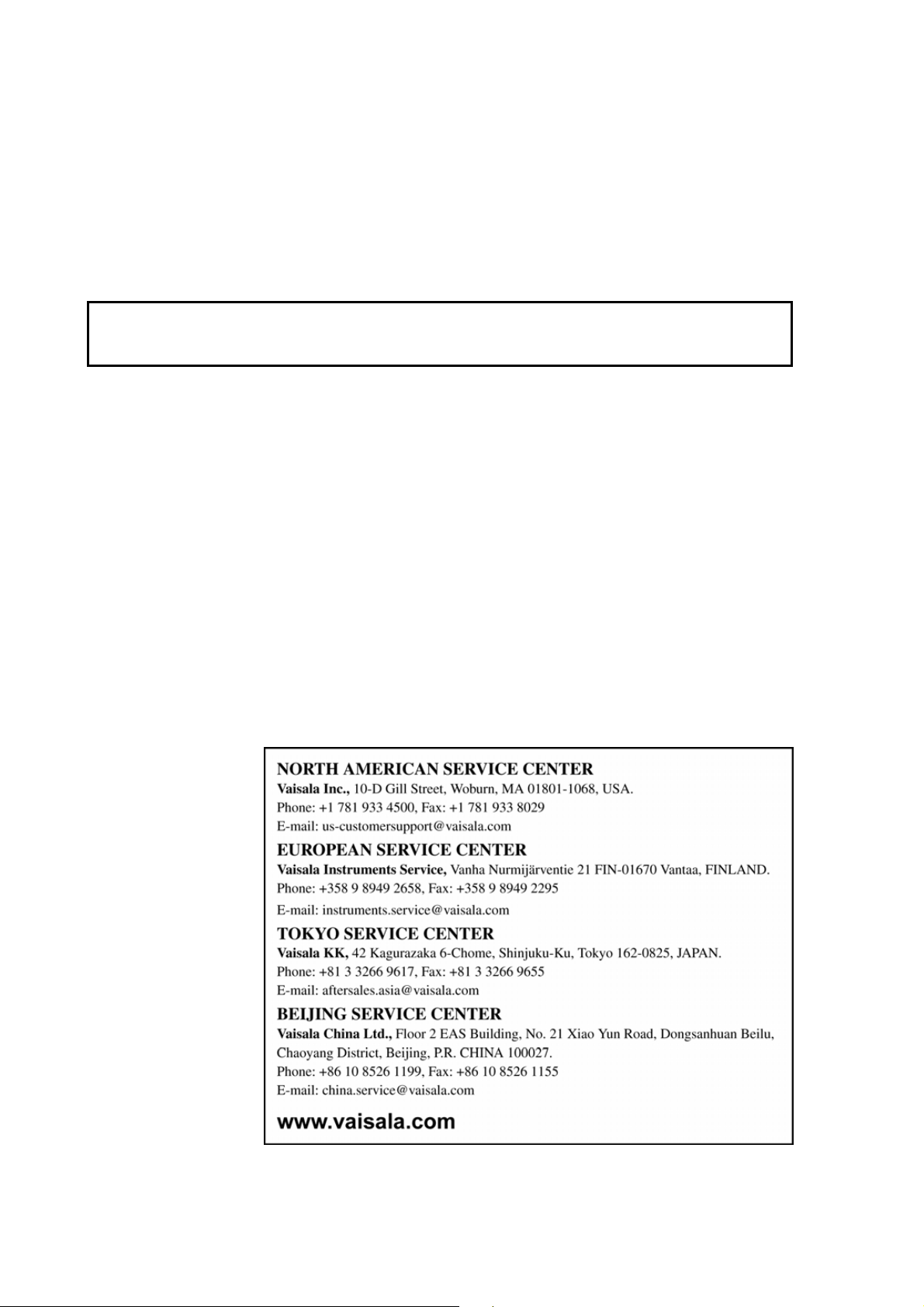
Vaisala Service Centers
Send the device to Vaisala Instruments Service Centre for calibration
and adjustment, see contact information below.
If the product needs repair, please contact Vaisala Instruments Service
Center in your region. Follow the instructions given to you to speed
up the process and to avoid extra costs.
30 ___________________________________________________________________ M210397EN-D
Page 41

Chapter 7 ____________________________________________________________ Troubleshooting
CHAPTER 7
TROUBLESHOOTING
This chapter describes the error states and provides contact
information for technical support.
Error States
- Analog 4-20 mA current output in error state: error state value for
the analog current output is 0 mA.
- Analog voltage output in error state: error state value for the
analog voltage output is 0V.
- Serial output in error state: serial line outputs asterisk characters
(*** **) to indicate an error sate.
In the case of an error, reset the transmitter by disconnecting the
power or issuing the RESET command on the serial line. If the source
of error is not found and the transmitter does not return to the normal
state with the reset, please contact Vaisala Instruments Service or
local Vaisala representative, see section Vaisala Service Centers on
30.
page
Technical Support
For technical questions, contact the Vaisala technical support:
E-mail helpdesk@vaisala.com
Fax +358 9 8949 2790
VAISALA________________________________________________________________________ 31
Page 42

User's Guide _______________________________________________________________________
This page intentionally left blank.
32 ___________________________________________________________________ M210397EN-D
Page 43

Chapter 8 _____________________________________________________________ Technical Data
CHAPTER 8
TECHNICAL DATA
This chapter provides the technical data of Dewpoint Transmitter
DMT142.
Specifications
Table 7 Measured Variable
Property Description / Value
Dewpoint temperature
Measurement range -80 ... +60 °C (-112 ... +140 °F) Td
Standard version -60 ... +60 °C (-76 ... +140 °F) Td
Analog output scalings
option 1
option 2
option 3
Accuracy
(-60 … +60 C / -76 ... +140 °F)
Standard version (-50 … +60 C)
When the dewpoint is below 0 °C
(32 °F) the transmitter outputs
frostpoint
Response time 63% [90%] at
+20 °C gas temperature and 1 bar
pressure
-60 → -20 °C Td (-76 → -4 °F Td) 5 s [10 s]
-20 → -60 °C Td (-4 → -76 °F Td) 45 s [10 min]
ppm volume concentration
Measurement range 70 … 200 000 ppm
Accuracy at +20 °C (+68 °F),
1013 mbar
see graph on page
-80 ... +20 °C (-112 ... +68 °F) T
-60 ... +40 °C (-76 ... +104 °F) T
free scaling
± 3 °C (± 5.4 °F) T
7.3 ppm + 9.2 % of reading
34
d
d
d
VAISALA________________________________________________________________________ 33
Page 44
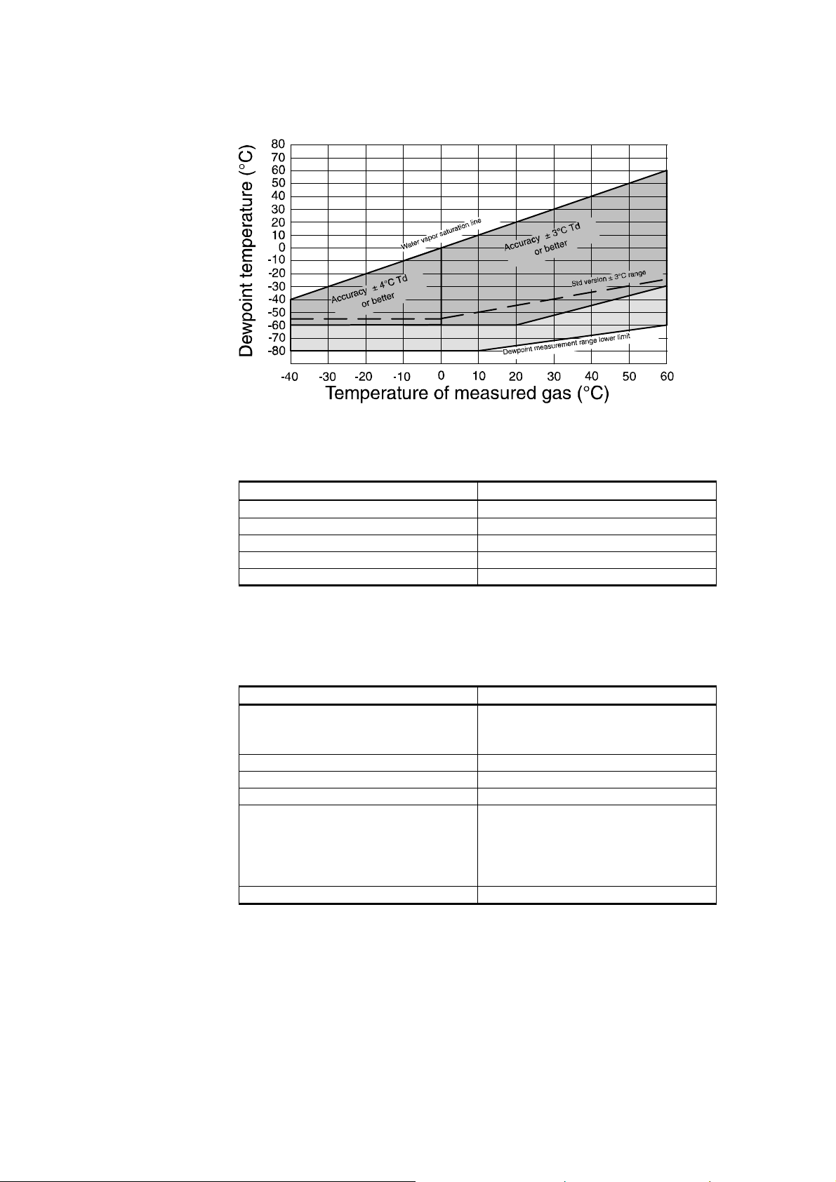
User's Guide _______________________________________________________________________
0610-073
Figure 19 DMT142 Dewpoint Measurement Accuracy Graph
Table 8 Operating Environment Specifications
Property Description / Value
Temperature 1) 0 … +60 °C (+32 ... +140 °F)
Relative humidity 0 ... 100 %RH
Pressure 1) 0 ... 50 bara (0 ... 725 psia)
Sample flow rate no effect on measurement accuracy
Measured gases noncorrosive gases
1) For extended temperature down to -40 °C (-40 °F) or pressure up to 50 bar
supply voltage must be 24 … 28 VDC
(725 psia) the
a
Table 9 Output Specifications
Property Description / Value
Analog output (scalable) 4 ... 20 mA (three-wire)
0 ... 1 V
0 ... 5 V
Resolution for current output 0.002 mA
Resolution for voltage output 0.3 mV
Typical temperature dependance 0.005 % of span/°C
Connector 4-pin M8 (IEC 60947-5-2)
AERO AE65-221-FA35PN (DMT142
PALL OEM model)
2 m connection cable with snap-on
or thread locking available
RS232 serial line for service use with DMT142RS cable
34 ___________________________________________________________________ M210397EN-D
Page 45

Chapter 8 _____________________________________________________________ Technical Data
Table 10 General Specifications
Property Description / Value
Sensor Vaisala DRYCAP®180D
Measured gases noncorrosive gases (SF6 gas with
special model)
Recommended calibration interval to
confirm the specified accuracy
Operating voltage
with current output
with voltage output
Supply current
during measurement
during auto-calibration
during sensor purge
Load for current output max 500 Ω
Load for voltage output min 10 kΩ
Housing material stainless steel (AISI 316L)
Mechanical connection G1/2" ISO 228/1 thread with bonded
Housing classification IP65 (NEMA 4)
Storage temperature range -40 ... +80 °C (-40 ... +176 °F)
Weight 118 g (4.16 oz)
2 years
18 ... 28 VDC
12 ... 28 VDC
10 mA + load current
max 220 mA pulsed
max 220 mA pulsed
plastic cap (ABS/PC)
stainless steel sintered filter
(part no. DRW010335)
seal ring (U-seal)
VAISALA________________________________________________________________________ 35
Page 46

User's Guide _______________________________________________________________________
Spare Parts and Accessories
Order Code Description
211598 M8 output cable 2 m with snap-on
locking (IEC 60947-5-2)
HMP50Z032 Shielded M8 output cable 0.32 m
with thread locking
HMP50Z300 Shielded M8 output cable 3 m with
thread locking
HMP50Z500 Shielded M8 output cable 5 m with
thread locking
HMP50Z1000 Shielded M8 output cable 10 m with
thread locking
DMT142RS RS232 serial line service cable
211917ZZ Connection cable for DM70
DM240FA Installation flange
DRW010335 Stainless steel sintered filter, 32 µm
Sampling cells
DMT242SC Sampling cell
DMT242SC2 Sampling cell with 1/4" Swagelok
connectors
DSC74 Sampling cell with quick connector,
leak screw and thread adapters
DSC74B Two-pressure sampling cell
DSC74C Two-pressure sampling cell with coil
DMCOIL Separate cooling/venting coil for
sampling cells
36 ___________________________________________________________________ M210397EN-D
Page 47

Chapter 8 _____________________________________________________________ Technical Data
Dimensions in mm (inches)
0507-107
Figure 20 DMT142 Dimensions
Wiring Quick Reference
Wiring of the connector
1 = VDC supply + (brown)
2 = signal sense – (voltage output only) (white)
3 = VDC supply – (blue)
4 = signal + (black)
3
0507-097
1
24
VAISALA________________________________________________________________________ 37
Page 48

Page 49

Page 50

www.vaisala.com
 Loading...