

Page 1

CEILOMETER
CT25K
User’s Guide
CT25K-U059en-2.1
26 February 1999
Vaisala 1999
Page 2

© Vaisala 1999
No part of this manual may be reproduced in any form or by any means,
electronic or mechanical (including photocopying), nor may its contents be
communicated to a third party without prior written permission of the
copyright holder.
The contents of instruction manuals are subject to change without prior
notice.
Page 3

Ceilometer CT25K
CT25K-U059en-2.1 User’s Guide
Contents
LIST OF FIGURES............................................................................................................ IV
INTRODUCTION TO M ANUAL ........................................................................................ VII
VALIDITY OF T HIS M ANUAL.........................................................................................VIII
SAFETY SUMM ARY.........................................................................................................IX
1. GENERAL INFORMATION....................................................................................... 1
1.1 Product Overview.......................................................................................... 1
1.2 Specifications................................................................................................ 3
1.2.1 Mechanical................................................................................... 3
1.2.2 External Connector J1 - Window conditioner ................................ 3
1.2.3 External Connector J2 - Power inpu t ............................................ 3
1.2.4 Output Interface ........................................................................... 4
1.2.4.1 External Connector J3 - Data line................................................. 4
1.2.4.2 External Connector J4 - Mainte nanc e li ne .................................... 6
1.2.5 Modem Options ............................................................................ 6
1.2.5.1 Modem board DMX5 5................................................................... 6
1.2.5.2 Modem board DMX5 0................................................................... 7
1.2.5.3 ANet Interface DMX611............................................................. 7
1.2.6 Transmitter................................................................................... 8
1.2.7 Receiver....................................................................................... 8
1.2.8 Optical System ............................................................................. 9
1.2.9 Performance ................................................................................. 9
1.2.10 Environmenta l Con ditio ns............................................................. 9
2. INSTALLATION ...................................................................................................... 10
2.1 Unloading and unpacking........................................................................... 10
2.2 Foundation................................................................................................... 11
2.3 Assembling the Unit.................................................................................... 12
2.4 Using the Tilt Feature.................................................................................. 14
2.5 Cable Connections...................................................................................... 15
2.6 Grounding.................................................................................................... 16
2.7 Connection of Maintenance Terminal ........................................................ 17
3. START UP.............................................................................................................. 19
3.1 Start up procedure ...................................................................................... 19
3.1.1 Mobile operation aspects............................................................ 21
3.2 Verification of Proper Op eration ................................................................ 21
3.3 Settings for Normal Operation.................................................................... 22
3.4 Factory settings of user progra mmable p arameter s................................. 22
4. OPERATION........................................................................................................... 25
4.1 Operation Modes ......................................................................................... 25
4.2 Serial Lines. Open and Closed Port ........................................................... 25
4.3 User Commands .......................................................................................... 27
4.4 Data Messages ............................................................................................ 33
i
Page 4

Ceilometer CT25K
User’s Guide CT25K-U059en-2.1
4.4.1 Data Message No. 1 ...................................................................33
4.4.2 Data Message No. 2 ...................................................................36
4.4.3 Data Message No. 3 ...................................................................38
4.4.4 Data Message No. 4 ...................................................................39
4.4.5 Data Message No. 5 ...................................................................39
4.4.6 Data Message No. 6 ...................................................................39
4.4.7 Data Message No. 7 ...................................................................40
4.4.8 (Spare) .......................................................................................41
4.4.9 (Spare) .......................................................................................41
4.4.10 DMX611 operation ( optio n) .........................................................41
4.4.11 Status Message "S" .................................................................... 42
4.4.12 Manual Message .........................................................................45
4.5 Polling mode ................................................................................................45
4.6 Prevailing parameter settings .....................................................................46
4.7 Manual angle setting ...................................................................................47
5. FUNCTIONAL DESCRIPT ION ................................................................................49
5.1 Theory of Operation.....................................................................................49
5.2 Technical Description..................................................................................53
5.2.1 General .......................................................................................53
5.2.2 LIDAR Measurement ...................................................................55
5.2.3 Internal Monitorin g and Co ntrol...................................................58
5.3 Module Descriptions....................................................................................58
5.3.1 Optical Subassem bly CTB22.......................................................58
5.3.2 Laser Transmitter CT T 21............................................................59
5.3.3 Receiver CTR21 .........................................................................60
5.3.4 Optics Monitor CTL21 .................................................................61
5.3.5 Board Frame DMF51 ..................................................................62
5.3.6 Processor Board DMC50B ..........................................................63
5.3.7 DC Converter DPS52.................................................................. 67
5.3.8 Ceilometer Interface Board DCT 51 .............................................69
5.3.9 Line and Power Int erface S ubas sem bly CT P241 ........................70
5.3.10 Internal Heaters Subas sem bl y CT25039.....................................72
5.3.11 Tilt Angle Sensor CT3675 ...........................................................73
5.3.12 Window Conditioner CT 2614 / CT2688 .......................................74
5.3.13 Maintenance Term inal PSION 3 (Optio n) .....................................75
5.3.14 Modem DMX55 (Opti on) .............................................................76
5.3.15 Modem DMX50 (Opti on) .............................................................78
5.3.16 DMX611 ANet Interface (Option)..............................................80
5.4 Sky Condition Algorithm .............................................................................83
5.4.1 General.......................................................................................83
5.4.2 Option code ................................................................................83
5.4.3 Activation.................................................................................... 83
5.4.4 Algorithm overvie w......................................................................84
6. PERIODIC M AINTENANCE ....................................................................................87
6.1 Alarms and warnings...................................................................................87
6.2 Window Cleaning .........................................................................................87
6.3 Battery check ...............................................................................................88
6.4 Storage.........................................................................................................88
7. TROUBLESHOOTING ............................................................................................89
7.1 Normal Operation .........................................................................................89
7.1.1 Equipment ..................................................................................89
ii
Page 5

Ceilometer CT25K
CT25K-U059en-2.1 User’s Guide
7.1.2 Instructions ................................................................................. 89
7.2 Troubleshooting.......................................................................................... 93
7.2.1 Warnings.................................................................................... 93
7.2.2 Alarms........................................................................................ 96
7.2.3 Miscellaneous............................................................................. 97
7.3 Failure Diagnosis ........................................................................................ 98
8. REPAIR.................................................................................................................. 99
8.1 General......................................................................................................... 99
8.2 Writing conventions used........................................................................... 99
8.3 Start-up procedure for replacem ent (all parts).........................................100
8.4 Transmitter CTT21......................................................................................101
8.4.1 Removal....................................................................................101
8.4.2 Replacement .............................................................................102
8.4.3 Compensation a djustm ents .......................................................105
8.5 Receiver CTR21 ..........................................................................................108
8.5.1 Removal....................................................................................108
8.5.2 Replacement .............................................................................109
8.5.3 Coaxial Cable Rep lacem ent ......................................................111
8.5.3.1 Removal....................................................................................111
8.5.3.2 Replacement .............................................................................112
8.6 Compensation Fiber...................................................................................113
8.6.1 Compensation Fi ber re placem ent..............................................113
8.7 Optics Monitor CTL21 ................................................................................114
8.7.1 Removal....................................................................................114
8.7.2 Replacement .............................................................................115
8.8 Boards of Board Fram e DM F51 .................................................................116
8.8.1 Removing boards ......................................................................116
8.8.2 Replacing boards ......................................................................117
8.8.2.1 Parameter settings of Ceilom eter I nterfac e bo ard DCT5 1 .......... 117
8.9 Line & Power Subassembly CTP241 .........................................................117
8.9.1 Removal....................................................................................117
8.9.2 Replacement .............................................................................119
8.9.3 Internal Heater S ubas sem bly CT25 03 9 Rep lacem ent ................ 120
8.9.4 Battery 4592 replac em ent instruc tions.......................................121
INDEX.......................................................................................................................... ... 123
iii
Page 6

Ceilometer CT25K
User’s Guide CT25K-U059en-2.1
LIST OF FIGURES
Figure 1-1 Ceilometer CT25K ..........................................................................................1
Figure 1-2 Data Line Connection Options......................................................................... 5
Figure 2-1 Measurement Unit Handle.............................................................................10
Figure 2-2 Foundation Construction ...............................................................................11
Figure 2-3 Mounting the Pedestal ................................................................................... 12
Figure 2-4 Attaching the Measurement Unit and the Shield............................................13
Figure 2-5 External Connectors (bottom view) ...............................................................15
Figure 2-6 Termination Box Wire Connections .............................................................. 16
Figure 3-1 CT25K Switches and LEDs...........................................................................20
Figure 4-1 Operation Modes........................................................................................... 25
Figure 4-2 Open and closed port.....................................................................................26
Figure 5-1 Typical Measurement Signal .........................................................................49
Figure 5-2 Measurement Unit Components .....................................................................53
Figure 5-3 Subassembly Interconnections.......................................................................54
Figure 5-4 Block Diagram of Operational Units ............................................................. 56
Figure 5-5 Optical Subassembly CTB22 with Optics Monitor, Transmitter and Receiver
Subassemblies ............................................................................................... 58
Figure 5-6 CTT21 Block Diagram ..................................................................................59
Figure 5-7 CTR21 Block Diagram..................................................................................60
Figure 5-8 CTL21 Block Diagram ..................................................................................61
Figure 5-9 DMF51 Frame...............................................................................................62
Figure 5-10 DMC50B Block Diagram ............................................................................63
Figure 5-11 DIP Switch Settings of the DMC50............................................................. 66
Figure 5-12 DPS52 Block Diagram................................................................................. 67
Figure 5-13 DCT51 Block Diagram................................................................................69
Figure 5-14 CTP241 Wiring ...........................................................................................71
iv
Page 7

Ceilometer CT25K
CT25K-U059en-2.1 User’s Guide
Figure 5-15 CT25039 Wiring Diagram .......................................................................... 72
Figure 5-16 CT3675 Tilt Angle Sensor.......................................................................... 73
Figure 5-17 Window Conditioner CT2614/CT2688 ....................................................... 74
Figure 5-18 RS Cable..................................................................................................... 75
Figure 5-19 DMX55 Block Diagram.............................................................................. 76
Figure 5-20 DMX50 Block Diagram.............................................................................. 78
Figure 5-21 DMX611 Block Diagram............................................................................ 80
Figure 8-1 Board Connectors of the DMF51 Board Frame............................................101
Figure 8-2 Removing the Laser Transmitter..................................................................102
Figure 8-3 Adjusting the compensation.........................................................................106
Figure 8-4 Adjusting the compensation.........................................................................107
Figure 8-5 Removing the Receiver ................................................................................ 109
Figure 8-6 Removing the Optics Monitor ......................................................................115
Figure 8-7 Boards of the DMF51 Board Frame.............................................................116
Figure 8-8 Removing Line and Power Interface Subassembl y CTP241 .........................119
Figure 8-9 Internal heater replacement..........................................................................121
Figure 8-10 Battery replacement...................................................................................122
v
Page 8

Ceilometer CT25K
User’s Guide CT25K-U059en-2.1
This page intentionally left blank.
vi
Page 9

Ceilometer CT25K
CT25K-U059en-2.1 User’s Guide
INTRODUCTION TO MANUAL
The purpose of this User’s Guide is to be a general information source as well
as a detailed operational guide for the user of Ceilometer CT25K.
This document is divided into 8 chapters. Chapter 1 offers an overview and
technical specifications of the CT25K Ceilometer. The following chapters 2
and 3 contain installation and start up instructions. Operational instructions
with user commands and data messa ges are included in chapter 4. Chapter 5
includes functional description of the Ceilometer and chapters 6, 7 and 8
instructions for maintenance, troubleshooting and repair.
vii
Page 10

Ceilometer CT25K
User’s Guide CT25K-U059en-2.1
VALIDITY OF THIS M ANUAL
This manual covers ceilometer CT25K in all its configurations as defined by
the parts and options listed in section 1.1, running under software re vision
CT25K- 2.01 or 2.01a
Table 1-1 lists the revision history that may apply in comparison to other units
in use:
Software revision s Description
CT25K-1.01 First Release
CT25K-1.02 Intermediate release (not in us e)
CT25K-1.03 Intermediate release (not in us e)
CT25K-1.04 Production rev. 95-05-15...97-02-03
CT25K-1.04h Special rev. with Qualimetrics and
DR21 messages
CT25K-1.05 Production rev. 97-02-03...
CT25K-2.00 Production rev. 97-11-01...
CT25K-2.01 Production rev. 98-03-17...
CT25K-2.01a Production r ev. 99-02-09…
Table 1-1 Software Revisions
Table 1-2 lists the hardware history that may apply in comparison to other
units in use:
Hardware history Description
CT25K model A First Release
CT25K model B Enclosur e CT1669 replaced with CT15035.
Model A pedestal CT2665 (Fiberglass) is option
New Metal Pedestal CT25106 is standard.
Line and Power Interface Subassembly CTP21
changed to CTP241.
Internal Heaters Subassembl y CT2690 replaced
with CT25039.
CTB22 Replaces CTB21 since 97-05-26
DMC50B Replaces DMC50A since 97-11-05
DPS52 Replaces DPS51
Table 1-2 Hardware Hi sto ry
viii
Page 11
Ceilometer CT25K
CT25K-U059en-2.1 User’s Guide
SAFETY SUMMARY
The following safety precautions must be observed during all phases of
operation, service, and repair of this instrument. Failure to compl y with these
precautions or with specific wa rnings elsewhere in this manual violat es safety
standards of design, manufacture, and intended use of the instrument.
VAISALA assumes no liability for the customer’s failure to comply with these
requirements.
LASER SAFETY
The CT25K is officially certified as a Class 1 laser device in accordance with
European standard EN 60 825-1:1994. It is also classified in accordance w ith
U.S. regulation 21 CFR 1040 as a Class 1 laser device. This means that a
CT25K Ceilometer installed in a field environment with instrument covers on
and pointed vertically or near-vertically poses no established biological
hazard to humans.
The device is equipped with the following label:
The instrument is intended for operation in an area restricted from public
access, and to be pointed vertically or near-vertically up. The following
precautions are to be noted and followed during service and maintenance of
the instrument:
• Never look directly into the Laser Transmitter with magnifying optics
(glasses, binoculars, telescopes, etc.)
• When operating, avoid looking at the ceilometer unit from the beam
direction. When tilting the unit, make sure that it is not being viewed from
the beam direction with magnifying optics.
• Only trained personnel should perform maintenance fun ctions. Work area
access by unauthorized persons during service operations must be
prevented.
ix
Page 12

Ceilometer CT25K
User’s Guide CT25K-U059en-2.1
GROUND THE INSTRUMENT
To minimize shock hazard, the instrument chassis and cabinet must be
connected to an electrical ground. The instrument is equipped with a
three-conductor AC power connector. The power cable must either be
plugged into an approved three-contact electrical outlet or the instrument must
be carefully earthed to a low-resistance sa fet y ground.
DO NOT OPERATE IN AN EXPLOSIVE ATMOSPHERE
Do not operate the instrument in the presence of flammable gases or fumes.
Operation of any electrical instrument in such an environment constitutes a
definite safety hazard.
DO NOT SERVICE OR ADJUST ALONE
Do not attempt internal service or adjustment unless anothe r person, capable
of rendering first aid and resuscitation, is pres ent.
DO NOT SUBSTITUTE PARTS OR MODIFY INSTRUMENT
Because of the danger of introducing additional hazards, do not install
substitute parts or perform any unauthorized modification to the instrument.
Return the instrument to a VAISALA office or authorized Depot for service
and repair to ensure that safety features are maintained.
KEEP AWAY FROM LIVE CIRCUITS
Operating personnel must not remove instrument covers. Component
replacement and internal adjustments must be made by qualified maintenance
personnel. Do not replace components with power cable connected. Under
certain conditions, dangerous voltages may exist even with the power cable
removed. To avoid injuries, always disconnect powe r and discharge circuits
before touching them.
High voltage will be readily accessible when the transmitter (CTT21) or
receiver (CTR21) covers are removed and they are connected to a powered
unit. High voltage is present in the Line and Power Interface Subassembly
(CTP241), the Internal Heaters subassembly, the Frame (DMF51) Mother
Board, and the Window Conditioners at the top of the Shield.
Transmitter (CTT21), Receiver (CTR21), and Line and Power Input
Subassembly (CTP241) have the following warning label:
WARNING! +,*+9 2/7$*(, 16,' (7+,6( 1&/26 85(
x
Page 13
Ceilometer CT25K
CT25K-U059en-2.1 User’s Guide
Internal Heaters Subassembly can be hot and has the following warning
labels:
DANGEROUS PROCEDURE WARNINGS
Warnings, such as the example below, precede potentially dangerous
procedures throughout this manual. Instructions contained in the warnings
must be followed:
WARNING
Dangerous voltages, capable of causin g death, are present
in this instrument. Use extreme caution when handling,
testing, and adjusting.
CAUTION
The equipment contains parts and assemblies sensitive to
damage by Electrostatic Discharge (ESD). Use ESD
precautionary procedures when touching, removing or
inserting.
xi
Page 14

Ceilometer CT25K
User’s Guide CT25K-U059en-2.1
This page intentionally left blank.
xii
Page 15
Ceilometer CT25K
CT25K-U059en-2.1 User’s Guide
1. GENERAL INFORMATION
1.1 Product Overview
Ceilometer CT25K measures cloud heights and vertical visibilities. The small
and lightweight measurement unit suits well for mobile operation.
The CT25K Ceilometer employs pulsed diode laser LIDAR technology
(LIDAR = Light detection and ranging), where short, powerful laser pulses
are sent out in a vertical or near-vertical direction. The reflection of light backscatter - caused by haze, fog, mist, virga, precipitation and clouds is
measured as the laser pulses traverse the sky. The resulting backscatter
profile, i.e. signal strength versus height, is stored and processed and the
cloud bases are detected. Knowing the speed of light, the time dela y between
the launch of the laser pulse and the detection of the backscatter signal
indicates the cloud base height.
The CT25K is able to detect three cloud layers simultaneously. Besides cloud
layers it detects whether there is precipitation or other obstructions to vision.
No adjustments in the field are needed. The embedded software includes
several service and maintenance functions and gives continuous status
information from internal monitoring. The software is designed to give the
full backscatter profil e.
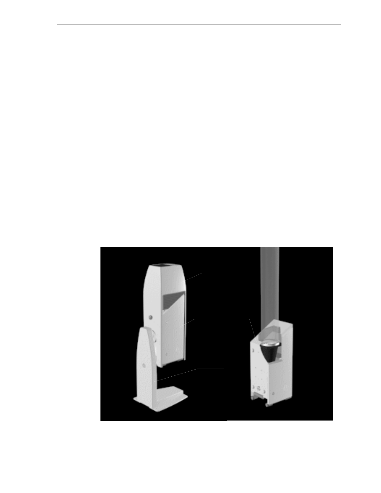
SHIELD
MEASUREMENT UNIT
PEDESTAL
9412-026
Figure 1-1 Ceilometer CT25K
1
Page 16

Ceilometer CT25K
User’s Guide CT25K-U059en-2.1
Ceilometer CT25K consists of three main parts (Figure 1-1):
1. Measurement Unit including
- Optical Subassembly CTB22
- Laser transmitter CTT21
- Receiver CTR21
- Optics Monitor CTL21
- Frame DMF51 including
- Processor Board DMC50B
- DC Converter DPS52
- Ceilometer Interface Board DCT51
- Modem (optional)
- Line and Power Interface Subassembl y CTP241
- No-Break Battery
- Internal Heaters Subassembly CT25039
- Tilt Angle Sensor CT3675
- Internal Cables etc.
2. Shield including
- Built-in Window Conditioner CT2614/CT2688 (warm air blower)
options - 220...240 VAC (CT2614)
- 100...115 VAC (CT2688)
3. Pedestal
- Metal pedestal CT25106 is standard. For off-shore applications it is
recommended to use fiberglass pedestal CT26 65.
The complete delivery also includes mating cables with connectors for power
and communication, installation hardware, an Allen key, a triangle ke y for the
Measurement Unit door and this CT25K User’s Guide.
In addition, the following options may be included in the delivery:
- Maintenance Terminal (Palmtop compute r) PS ION3
- connected to Measurement Unit at the external conn ector J4 via RS232 interface
- Termination Boxes (2) for Line Power CT3709 (external connector J2)
and Communication Cable CT3707 (external connecto r J 3) connections
- Tropics Window CT35043 on Measurement Unit instead of Standard
Window to protect the laser from direct sun radiation.
- Optical Termination Hood CT25184 for indoor service us e
2
Page 17

Ceilometer CT25K
CT25K-U059en-2.1 User’s Guide
- Shock Absorber CT35022 for ship installations
- PC Terminal cable CT35198 to connect the connector of the RS-232 p ort
of the PC to the maintenance port
1.2 Specifications
1.2.1 Mechanical
Dimensions:
Measurement unit 760 x 280 x 245 mm
(30 x 11 x 10 in.)
Height with shield and pedestal 1320 mm (52 in.)
Weight:
Measurement unit 17 kg (37 lb.)
Shield 10 kg (22 lb.)
Metal pedestal 8 kg (17 lb.)
Fiberglass pedestal (option) 13 kg (28 lb.)
Cardboard transport container size 1170 x 740 x 430 mm (46 x 29 x 17 in.)
Cardboard transport container weight 51 kg (111 lb.)
Plywood transport container size 1240 x 760 x 450 mm (49 x 30 x 18 in.)
Plywood transport container weight 70 kg (152 lb.)
1.2.2 External Connector J1 - Window conditioner
Connector J1: Type Binder series 693, 09-4228-00-07
(female)
Mating connector type: Type Binder series 693, 99-4225-70-07
7-pin (male) elbow
1.2.3 External Connector J2 - Power input
At nominal line voltage 115 V or 230 V
Power consumption (typical)
Total 365 W
Measurement unit 15 W
Internal heater 120 W
Window conditioner heater 200 W
Window blower 30 W
Frequency 45-65 Hz
3
Page 18

Ceilometer CT25K
User’s Guide CT25K-U059en-2.1
Power connector (J2): Type Binder series 693, 09-4223-00-04
4-pin (male)
Mating connector type: Type Binder series 693, 99-4222-70-04
(female) elbow
No-break power supply 12V Sealed Lead Acid Battery, 2 Ah
Overvoltage Protection Low-press filter , VDR
1.2.4 Output Interface
The data port can operate according to the following serial line standards :
RS-232
RS-422
RS-485, multidrop, 2-wire / 4-wire
The data port can also be operated through DMX55 and DMX50 modems or
ANet Bus interface DMX611.
The maintenance port is an RS-232 serial line, ex cept when the data line is set
to RS-422 or RS-485; then the maintenance line voltage levels become 0 and
+5 V.
1.2.4.1 External Connector J3 - Data line
The data line is intended to be used for measurement data communi cation, but
it can also be used with Ceilometer Maintenance Terminal, PC or other
terminals.
Connector (J3): Type Binder series 693, 09-4227-00-07
7-pin (male)
Mating connector type: Type Binder series 693, 99-4226-70-07
(female) elbow
Baud Rate: 2400 baud standard with RS-232
300, 4800 and 9600 baud available
300 bit/s with modem DMX55
2400 bit/s standard with modem DMX50
300, 1200, 2400 bit/s available
Data compression allows up to 9600 bit/s
throughput
Max. Distance to Operate: 300m (1000 ft) with RS-232,
4
1.2 km (4000 ft) with RS-422 and RS-485,
all at 2400 baud with typical communication
cables
16 km (10 mi) with Modem
Page 19
Ceilometer CT25K
CT25K-U059en-2.1 User’s Guide
Standard Character F rame: 1 Start Bit
7 Data Bits
Even Parity
1 Stop Bit
Standard Character Code: USASC II
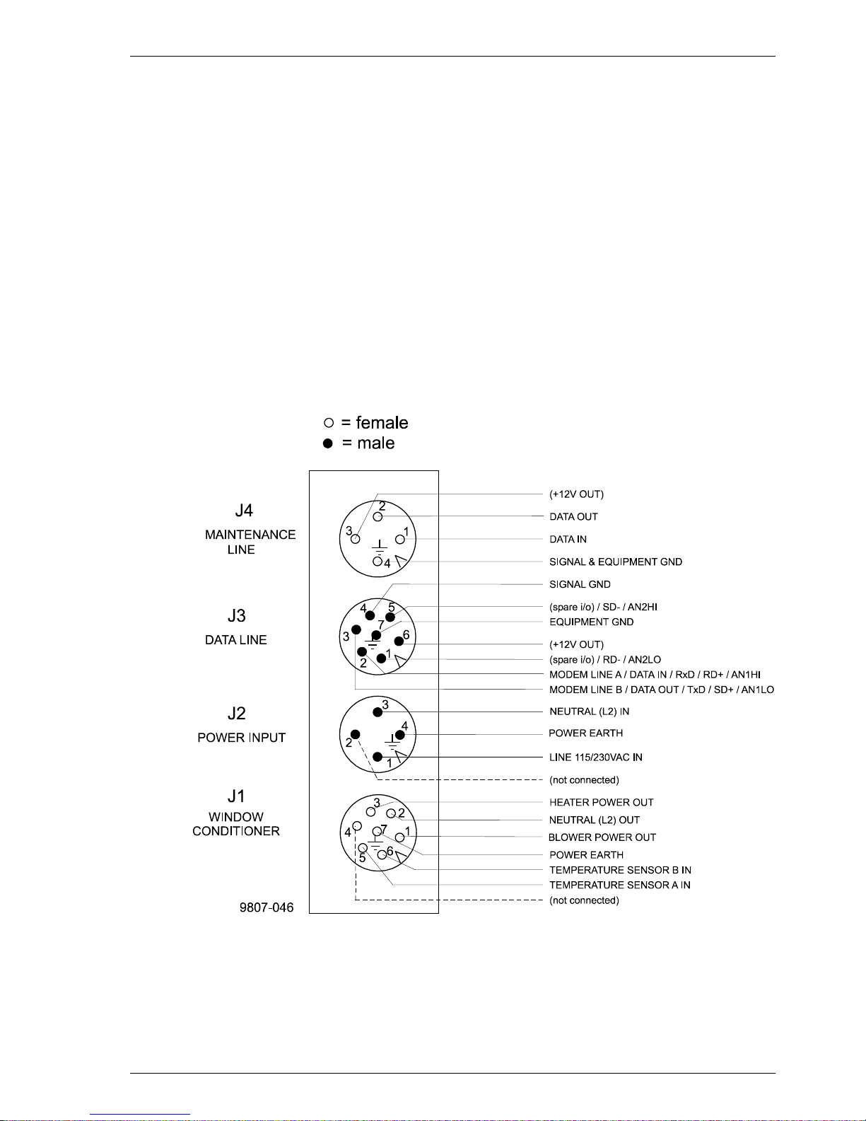
Pin Connections 1 RD- / AN2Lo
2 Modem Lead A / RxD / RD+ / AN1Hi
3 Modem Lead B / TxD / SD+ / AN1Lo
4 Signal Ground
5 SD- / AN2Hi
6 +12 V DC supply (200 mA max for 1
hour, 100 mA continuous, for external
equipment)
Modem circuits are non-polar and symmetrical. All modem circuits are
electrically floating to overvoltage protection ratin g (300V-500 V).
Overvoltage Protection in each circuit:
Primary Noble Gas Surge Arrester
Secondary VDRs, Transient Zener Diodes
or normal Diodes
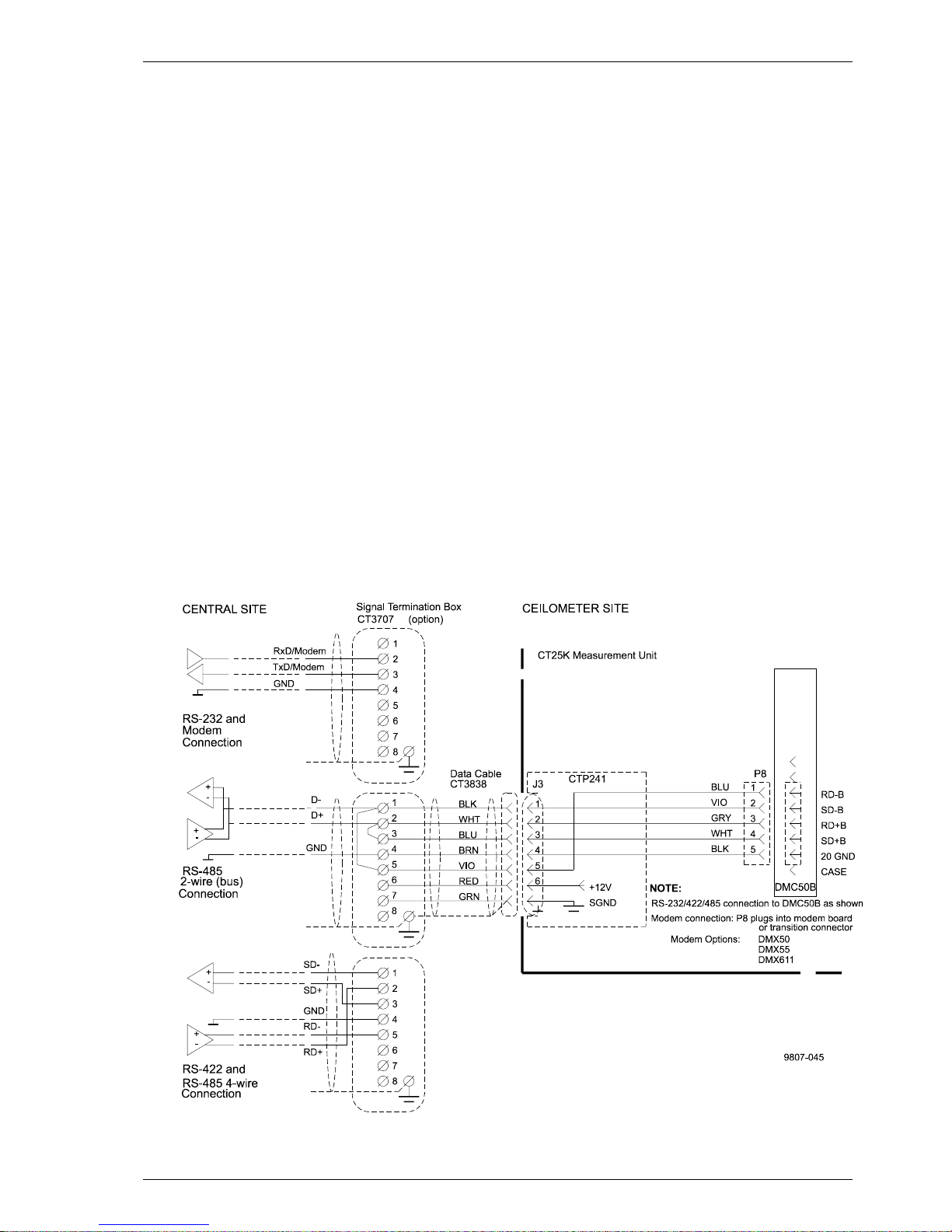
Figure 1-2 Data Line Connection Options
5
Page 20

Ceilometer CT25K
User’s Guide CT25K-U059en-2.1
1.2.4.2 External Connector J4 - Maintenance line
Maintenance line is intended for on-site maintenance and can be used with
Ceilometer Maintenance Terminal, PC or other terminal.
Connector (J3): Type Binder series 693, 09-4224-06-04
4-pin (male)
Mating connector type: Type Binder series 693, 99-4221-70-04
(female) elbow
Baud Rate: 2400 baud standard and default
300, 4800, 9600 baud available
Distance to Operate: 300 m (1000 ft) at 2400 baud with typical
communication cables
Standard Character F rame: 1 Start Bit
7 Data Bits
Even Parity
1 Stop Bit
Standard Character Code: USASC II
Pin Connections 1 RxD / RD+ (0...5 V)
2 TxD / SD+ (0...5 V)
3 +12 V DC supply from internal battery
(100 mA continuous, 200 mA max.)
4 Signal Ground / Equipment Ground
Overvoltage Protection in each circuit:
Primary Noble Gas Surge Arrester
Secondary VDRs, Transient Zener Diodes or
normal Diodes
1.2.5 Modem Options
1.2.5.1 Modem board DMX55
ITU-T V.21 / Bell 103 full duplex modem interface for serial asynchronous
data interchange
Data Rate: 300 bit/s
Modulation method: FSK
6
Page 21

Ceilometer CT25K
CT25K-U059en-2.1 User’s Guide
Answer Mode Standard Frequencies:
V.21 Bell 103
Mark (1) 1650 Hz 2225 Hz
Space (0) 1850 Hz 2025 Hz
Originate Mode Optional
Signal Level: -10 dBm (0.3 V) into 600 Ohm standard
(Jumper selectable)
Max. Distance to Operate 0...16 km (0...10 miles)
with 22 AWG (0.35 mm2) unshielded
twisted pair
The signal circuit is electrically floating to overvoltage protection rating
(300V-500V).
1.2.5.2 Modem board DMX50
Processor: Intel 80C32 custom version
Modem: Signal Processor Chip Silicon Systems SSI
73K224L
Modem standards supported: V.21/ V.22/ V.22bis and Bell 103, Bell 212
Modulation method: 300 FSK/ 1200 DPSK/ 2400 QAM
Compression & error correction: V. 42, V.42bis and MNP 2-5
Adaptive equalization for optimum performance over all lines.
1.2.5.3 ANet Interface DMX611
The DMX611 serves as an interface between the CT25K and Vaisala
proprietary ANet and INet busses.
Baud Rate 2400
Signal Level 0 dBm
Max. Distance to Operate 0…5 km multi-drop network
Standard Character Frame 8 Bit synchronous
Character Code Binary
iNet protocol Packet format.
Twisted pair 22 AWG
7
Page 22

Ceilometer CT25K
User’s Guide CT25K-U059en-2.1
1.2.6 Transmitter
Laser Source: Indium Gallium Arsenide (InGaAs) Diode
Laser
Center Wavelength: 905 ± 5 nm at 25 °C (77 °F)
Operating Mode: Pulsed
Nominal Pulse Properties at Full R ange Measu rem ent:
Energy: 1.6 µWs ± 20% (factory adjustment)
Peak Power: 16 W typical
Width, 50%: 100 ns typical
Repetition Rate: 5.57 kHz
Average Power: 8.9 mW (full range measurement)
Max Irradiance: 170 µW/cm ² measured wit h 7 mm aperture
Laser Classification: Officially certified as Class 1 laser device in
accordance with EN 60 825-1:1994
Class 1 in compliance with FDA CFR
1040.10 (Subsection e,3)
Laser Source Geometry: Five-stack, 0.4 mm (16 mil) square
Beam Divergence: ± 0.53 mrad edge, ± 0.75 mrad diagonal
1.2.7 Receiver
Detector: Silicon Avalanche Photodiode (APD)
Responsivity at 905 nm: 65 A/W
(factory adjustment)
Surface Diameter: 0.5 mm (0.02 in.)
Interference Filter: Center wavelength 908 nm typical
50% Pass Band: 35 nm at 890-925 nm typical
Transmissivity at 905 nm: 80 % typical, 70 % minimum
Field-of-View Divergence: ± 0.66 mrad
8
Page 23

Ceilometer CT25K
CT25K-U059en-2.1 User’s Guide
1.2.8 Optical System
Optics System Focal Length: 377 mm (14.8 in.)
Effective Lens Diameter: 145 mm (5.7 in.)
Lens Transmittance: 96 % typical
Window Transmittance: 98 % typical, clean
1.2.9 Performance
Measurement Range: 0...25,000 ft. (0...7.5 km)
Resolution: 50 ft
25,000 ft. Acquisition Time: min. 15 s
max. 120 s
Receiver Bandwidth: 3 MHz (-3db)
1.2.10 Environmental Conditions
Ambient Temperature: -50...+60 °C (-60 ...+140 °F)
Humidity: to 100 %RH
Wind: to 100 kt (50 m/s)
Vibration: 0.5 g 5 - 500 Hz
9
Page 24
Ceilometer CT25K
User’s Guide CT25K-U059en-2.1
2. INSTALLATION
NOTE
Before the installation, make sure that the CT25K
configuration, especially line voltage setting, is in
compliance with local circumstances. Information about
the CT25K configuration in question is included in the
delivery.
2.1 Unloading and unpacking
The CT25K is shipped in one container containing the Measurement Unit,
Shield and Pedestal, and all equipment, accessories an d docum entation ne eded
for carrying out the installation. Store the original packagin g for possible later
transport need.
For opening, the package is t o be placed on a flat surface with t he indicated
top side up. The container is opened from the top side and the ceilometer
including all other parts are carefull y removed.
• Use proper gloves for protection against sharp edges, et c.
• Avoid touching the window or lens surfaces unless cleaning according to
instructions.
• Maintain the integral protective caps on the unus ed external connectors (J3
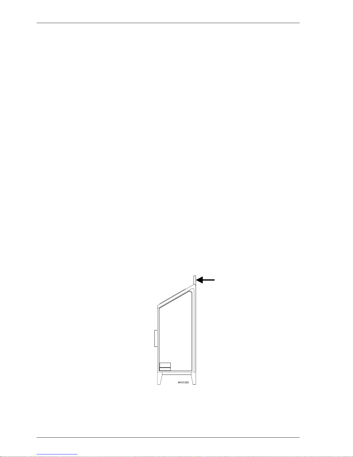
Data line or J4 Maintenance line).
• Use the measurement unit handle fo r lifting and carr ying (Figure 2-1).
If mishandling occurs during transit or installation, the instrument should be
returned to a VAISALA office or authorized Depot for insp ection.
10
Figure 2-1 Measurement Unit Handle
Page 25
Ceilometer CT25K
CT25K-U059en-2.1 User’s Guide
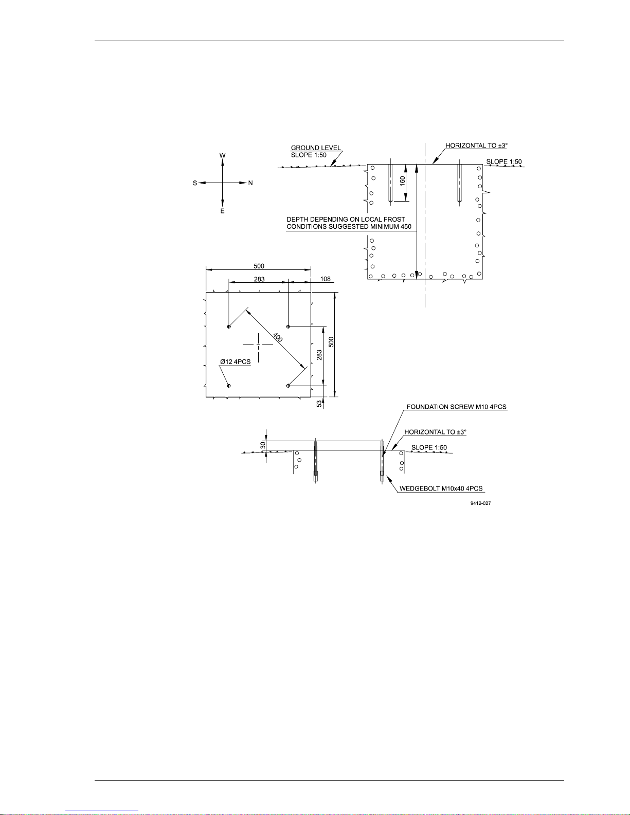
2.2 Foundation
The standard foundation for the CT25K ground installation is a concrete
foundation. The minimum dimensions suggested are present ed in Figure 2-2.
Mounting hardware is included with the delivery.
There are two alternative ways to make a foundation: to cast a new or to use
an existing foundation.
- If a new foundation is laid, the M10x40 Wedge Bolts and Foundation
Screws (4 each), are suggested to be cast into the concrete so that
approx. 30 mm (1.25 in.) of the foundation screw threads stand above
the surface.
- If an existing foundation is used, four holes of diameter 12 mm and
depth 165 mm (0.5 x 6.5 in.) are drilled into the concrete. The Wedge
Bolt and Foundation Screw combinations are placed in the holes, with
Wedge Bolts down; the protruding threads are alternately hammered
and tightened a few times so that the Wedge Bolts attach to the hole
walls.
In case the CT25K replaces a CT12K Ceilometer, the ex isting foundation and
screws can be used.
Figure 2-2 Foundation Construction
11
Page 26
Ceilometer CT25K
User’s Guide CT25K-U059en-2.1
If the tilt feature will be used (see section 2.4), observe this in the la yout of
the foundation screws and pedestal placement.
2.3 Assembling the Unit
The CT25K Ceilometer is assembled in four stages:
1. Mount the pedestal on the foundation.
2. Attach the measurement unit to the pedestal.
3. Mount the shield on the measurement unit.
4. Connect the external cabl es.
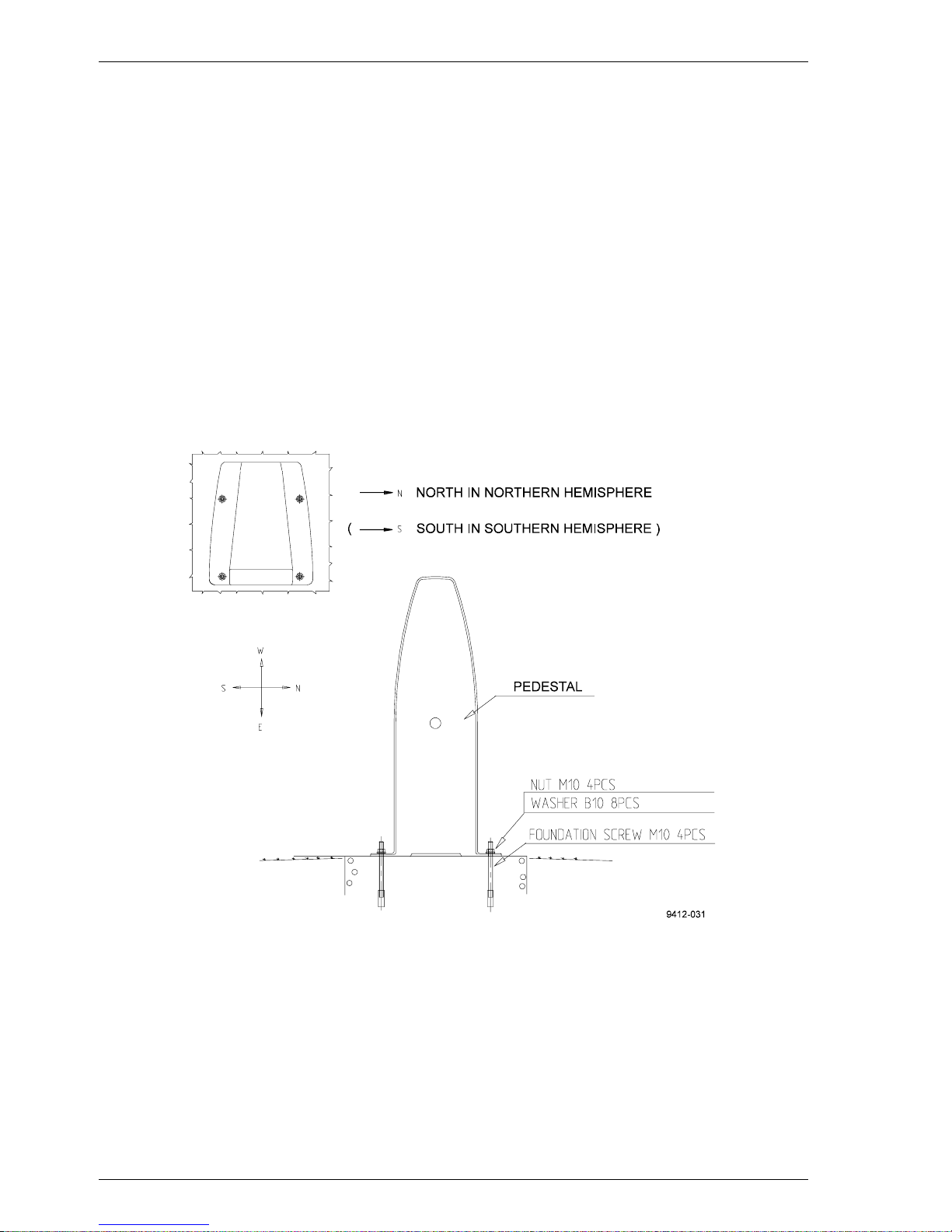
1. Place the Pedestal on the foundation (or equivalent installation place) so
that the vertical leg of the pedestal faces East in the Northern hemisphere,
and West in the Southern hemisphere.
If the tilt feature will be used (see section 2.4.), observe this in the layout of
the foundation screws and pedestal placement. Place the flat washers on the
foundation screws and fix the nuts (Figure 2-3).
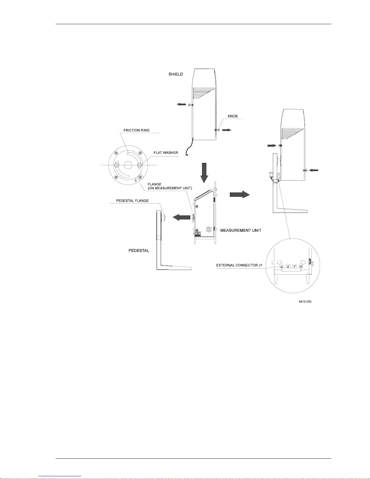
2. Start mounting the measurement unit by rotating the friction ring of the
flange to the position shown in Figure 2-4 (the screw h oles horizontally).
Remove the Allen head screws (2 pcs) and flat w ashers.
12
Figure 2-3 Mounting the Pedestal
Page 27
Ceilometer CT25K
CT25K-U059en-2.1 User’s Guide
Place the measurement unit on the pedestal flange. Attac h the pedestal flange
to the measurement unit by the two Allen head screws with flat washers. An
Allen key is included in the delivery.
Figure 2-4 Attaching the Measurement Unit and the Shield
3. Before placing the shield pull the knobs (pidgeon blue) on the shield
outwards. Place the shield carefully on the Measurement Unit; be careful
with the Window Conditioner cable. Tighten the two attachment knobs
(Figure 2-4).
Before connecting the Window Conditioner cable check that the voltage
rating of the Window Conditioner (written at its connector) is correct.
Connect the Window Conditioner cable plug of the shield to the
measurement unit external connector J1 .
Connect external cables according to section 2. 5.
13
Page 28

Ceilometer CT25K
User’s Guide CT25K-U059en-2.1
2.4 Using the Tilt Feature
The Measurement Unit and Pedestal of Ceilometer CT25K are designed so
that the unit can operate in a tilted direction. The built-in tilt angle sensor
CT3675 detects the tilt angle, i.e. deviation from the vertical. The tilt angle
ranges from -15 to +90 degrees from vertical; the angle is positive when the
measurement unit door turns towards the ground. The cosine of the tilt angle
is used for automatic correction of the detected cloud base height, which
enables accurate cloud base measurements also in a tilted direction.
Several advantages can be realized with the aid of this feature:
• Heavy weather conditions
Using a slight tilt angle for instance 15 degrees, the measurement unit
window is kept better protected from precipitation, thus enhancing the
availability of correct measurements in heavy weather conditions.
• Aircraft approaches
The beam can be directed towards a direction, which better r epresents the
approach of an aircraft than th e straight vertical. Useful e.g. for helicopter
approaches, and sites where the ceilometer cannot be located exactl y at the
desired spot.
• Hard target and testing purposes
Tilting the unit down by 90 degrees permits verification of operation
against a hard target at a known distance. Useful in connection with
installation and maintenance. Enables real backscatter signal detection
when there are no clouds in the sky.
WARNING
Make sure that nobody is viewing the unit from th e beam
direction with magnifying optics!
• Maintenance
By tilting the unit back -15 degrees, better access is gained to the interior
during maintenance.
• In the tropics
Between the latitudes of ± 25 degrees, where the sun can be straight above
the unit, a slight tilting prevents the laser from direct sun radiation, which
would otherwise destroy the laser. The other alternative is to use a tropics
window on the measurement unit instead of a stand ard window.
14
Page 29
Ceilometer CT25K
CT25K-U059en-2.1 User’s Guide
As these advantages are partly contradictory and cannot or need not all be
realized, the user must decide the final installation direction. In doing so, the
following must be observed:
NOTE
Unless a tropics window is used, the unit must never be
directed so that the sun shines directly into the optics,
because the lens will focus all radiation into a very hot
spot.
2.5 Cable Connections
All external connectors to the Measurement Unit are located at th e bottom left
edge as seen from the door direction. Figure 2-5 shows the external
connectors J1, J2, J3 and J4.
• The Window Conditioner (warm air blower) mounted in the Shield is
permanently connected to J 1.
• Line Power input is connected to J2.
Figure 2-5 External Connectors (bottom view)
15
Page 30

Ceilometer CT25K
User’s Guide CT25K-U059en-2.1
• Remote communication is normally connected to J3.
• A local maintenance terminal, for example PSION3, is intended to be
connected to J4. A protective cap is included for covering J4 when not in
use.
External mating connectors with 2 m (7 ft.) cable are included for J2 and for
J3. The power plug of the J2 cable can be cut when the unit is permanentl y
installed at the final site.
The cables for J2 and J3 are intended to be drawn through the hole of the
pedestal to the connectors. Provide sufficient slack for permitting the unit to
be tilted later.
Figure 2-6 shows the connecting signal leads with optional Powe r and Signal
Termination Boxes.
Figure 2-6 Termination Box Wire Connections
Suggested wire dimensions for the external cablin g are:
Line Power Supply: 3 x 1.5 mm2 (AWG 16)
Remote Communication: 0.35 mm2 (AWG 22) twisted pair with shield
When permanent line power installation is made, the
maximum size of the fuse protecting the power line is 10 A
2.6 Grounding
The power supply connector J2 provides a standard protective ground for the
instrument chassis.
16
NOTE
Page 31

Ceilometer CT25K
CT25K-U059en-2.1 User’s Guide
The CT25K is equipped with a separate grounding screw o n the measurement
unit flange for external earthing (see Fi gure 2-4).
CONNECTION TO A SOLID EARTH GROUND AT THE
INSTALLATION SITE IS MANDATORY FOR ADEQUATE
LIGHTNING AND TRANSIENT PROTECTION.
2.7 Connection of Maintenance Terminal
Any terminal or PC with serial interface and terminal emulation program can
be used for operation and maintenance of the CT25K Ceilometer. A standa rd
Maintenance Terminal option is offered including the following components:
• Palmtop Computer PSION3
• RS cable (RS-232 Interface)
• Terminal Cable CT3840
• Technical Manuals for the Palmtop Computer
Setting up PSION3
To set up PSION3 for communication for the first time the following steps are
needed. These settings must be done with the RS cable attached to PSION3.
The PSION3 has two normal Mignon AA batteries, which enable operation
for twenty hours.
1. Connect the RS cable to th e PS ION3 comput er.
2. Press the System icon to start the computer.
3. Press the "Menu" key to get the menu on the screen.
4. Select the "Install" from the "Apps" menu.
5. Use cursor keys to move to the "Disk" line and to the "C" disk.
6. See that the "File: Name" line has "Comms.app" . If the line does not
have it add it by typing and press ENTER.
A new icon "Comms" is now installed and can be seen on the System screen.
The terminal emulation i s read y.
7. Choose "Comms" from System screen and press ENTER to start it.
8. Press the "Menu" ke y and set "Port " from "Sp ecial " menu as follo ws:
Baud rate 2400
Data bits 7
Stop bits 1
Parity Even
Ignore parity Yes
17
Page 32

Ceilometer CT25K
User’s Guide CT25K-U059en-2.1
9. Exit from "Comms" and select "Save the Setting" from "File" menu
by name "CT25K".
Now there should be the text "CT25K" under the "Comms" applic ation. From
now on PSION3 is ready to communicate with CT25K whenever "CT25K"
from the "Comms" application is chosen.
Connecting PSION3 to CT25K
Connect the cables as follo ws:
1. Connect the Terminal Cable CT3840 to the external connector J4 of
the Ceilometer.
2. Connect the RS cable to the Maintenance Cable
3. Connect the RS cable to the P SION3 com puter.
Operation
Turn on both equipments, the CT25K and the PSION3 computer.
4. PSION3 is turned on for normal operation b y pressing the key "Esc"
or by pressing the special "Psion" key (∪) together with "ON".
5. PSION3 is turned off by pressing the "Psion" key (∪) and "OFF"
Choose the configuration CT25K from the System screen and pr ess ENTER.
The terminal is now ready for dialogue communication with the ceilometer.
Start the program by pressing ENTER. The prompt "CT:"should appear on
the screen. If not, check the cables and port settings (see Setting up PSION3
above).
The port has to be opened by command "OPEN" for giving commands. The
prompt CEILO> should appear. See Chapter 4 Ope ration.
For more information about communication see PSION3 manual included in
the delivery.
18
Page 33

Ceilometer CT25K
CT25K-U059en-2.1 User’s Guide
3. START UP
3.1 Start up procedure
Open the unit door; the key is included in the delivery. Mak e a visual check o f
the internal connectors, subassemblies, etc. Figure 3-1 describes the switches
and LEDs needed to complete the start up procedure.
1. Turn the main circuit breaker F1 to "OFF" position.
2. Plug in the line supply cable to connector J2 after checking the voltage of
the power supply cable connector.
3. Turn the Main Circuit Breaker F1 and the Battery Switch to the "ON"
position. After initialization routines the following shall happen (LED =
Light Emitting Diode):
DC Converter DPS52 LED D2 stable green
LED D1 blinking yellow
In case the built-in battery is deeply discharged it m ay take hours before
LED D2 goes on.
4. Processor Board DMC50B LED STATUS blinking at regular intervals
(1 sec.)
5. Ceilometer Interface Board DCT51 green LED D4 goes on during the
laser pulse train for about 12 seconds and is repeated according to the
configuration in question. After power-up, it may tak e a couple o f minutes
before the unit starts normal operation.
If LEDs operate in a different way than described above, the unit may need
service or maintenance. Refer to Chapter 7 Troubleshootin g.
19
Page 34

Ceilometer CT25K
User’s Guide CT25K-U059en-2.1
20
Figure 3-1 CT25K Switches and LEDs
Page 35

Ceilometer CT25K
CT25K-U059en-2.1 User’s Guide
3.1.1 Mobile operation aspects
The small and lightweight CT25K Ceilometer is suitable also for mobile
operation. It has a built-in 12V battery, which enables operation without
external power supply for about an hour in normal room temper ature.
NOTE
For switching power to the CT25K fully OFF, turn also
the Battery Switch OFF in addition to the line power
switch. Having the unit ON with battery supply only will
drain the battery.
NOTE
Do not attempt to carry a fully assembled unit alone. Lift
the CT25K from Measurement Unit Base or Pedest al only
(not from the shield). The three main parts - Measurement
Unit, Shield and Pedestal - can be lifted and carried
separately by one person.
3.2 Verification of Proper Operation
Proper operation of the Ceilometer can be checked with help of the
maintenance terminal. Turn the power on. After 30-45 seconds ask for the
status message with the command GET STATUS. Information about
commands can be found in chapter 4 Operation. The message should not
contain any warnings or alarms. In the opposite case see Chapter 7
Troubleshooting.
If a solid, stable cloud base is present at a range of 1,000-5,000 ft., and no fog
or precipitation is present, a quick-check of the detection and the unit
sensitivity can be carried out by observing the variable SUM on the third line
of data message No.2. SUM indicates the sum of detected and normalized
backscatter and its value should be in the range 150...200 if parameter SCALE
has the standard value 100 %. See para graph 4.4.2 for details.
If suitable clouds are not present for proper operation verification, the unit
may be tilted towards a hard target at known distance. The minimum distance
to the hard target should be at least 300 meters (1,000 ft.). Unexpected
behavior is not totall y excluded if e. g. a stron g refl ector sat urates th e recei ver.
When tilting the unit, make sure that nobod y is wat ching it
with binoculars or other magnifying optics.
WARNING
21
Page 36

Ceilometer CT25K
User’s Guide CT25K-U059en-2.1
3.3 Settings for Normal Operation
Switch settings for normal operation are as follows:
Main circuit breaker F1 ON
Window conditioner circuit breaker ON
Battery switch ON
Data message and interface configuration and the configuration of measuring
interval and transmission speed are standard factory settings. When required,
the settings can be changed by giving commands with the terminal.
During the factory alignment procedur e, the optical adjustments are caref ully
carried out to fulfill the requirements and specifications of the device. Optical
adjustments have been made at factory or depot, thus there is no need to
readjust in the field.
3.4 Factory settings of user programmable parameters
Table 3-1 next page shows the standard factory settings of user programmable
parameters. The prevailing parameter settings can be seen by the command
GET parameter_group
Parameter groups are displayed as bold text in table 3-1. As response to the
command a list of parameters with prevailing parameter values is shown.
The standard factory-set param eter valu es, which ma y be ch anged b y the us er,
are collected in the second column in table 3-1. The values displayed in the
first column are factory settings that the user cannot change. For changing a
value to the desired content and function, depending on the particular
installation, the corresponding command is
SET parameter_group parameter
22
Page 37

Ceilometer CT25K
CT25K-U059en-2.1 User’s Guide
Table 3-1 Factory paramete r settin gs
Response to User’s Menu
commands...
CEILO>get...
...data_acq
AUTOADJUSTMENTS: ON
DATA-ACQ. INTERVAL: 15 SEC. 15... 120 seconds availa ble
RECEIVER
GAIN: H
BANDWIDTH: N
SAMPLING RATE: 10 MHz Constant
TRANSMITTER
LENGTH OF PULSE: L
POWER OF PULSE: 188 Varies with unit, temperature, and
QUANTITY OF PULSES: 64K Constant
COMPENSATION
COARSE COMPENSATION: 13 Varies with unit and
FINE COMPENSATION: 125 Varies with unit and
...message
MESSAGE
ANGLE CORRECTION: ON Shall be ON if unit is operated
HEIGHT OFFSET: 0 Insert i nstallati on heig ht if sig nifi-
MODE: AUTOSEND Option POLLING. Transmits date
NOISE H2 COMPENSATION: OFF Option: ON. Affects the visual
PROFILE SCALE: 100 % Scales backscatter values of
PORT: DATA Optional selecti on:
TYPE: MSG1 Message No. 1. Options: MSG2,
UNITS: FEET Option: METERS. Note also
WARNING DELAY: OFF Option ON. Sets a 5 minutes delay
Standard fac tor y
settings of User’s
Menu parameters
Notes
age
contamination
contamination
tilted. May be ON even if u nit is
operated vertical. Option OFF will
turn detected values into dista nces
rather than heights.
cantly different from reference
(zero) heig ht, i n re port ing unit s.
message only whe n polled.
appearance of message No. 2
graphical presentation. Selection
OFF gives less noisy appearance.
message No. 2 an d cor res pond in g
SUM value.
MAINTENANCE.
MSG3, MSG6, MSG7 and
Status (S).
HEIGHT OFFSET.
for warning
23
Page 38

Ceilometer CT25K
User’s Guide CT25K-U059en-2.1
...oper_mode
OPERATION MODE: CONTINUOUS Option STANDBY requires
command START for carrying out
each cycle.
…options
[MODEM NAME]
SKY CONDITION:
HUMITTER:
BLOWER:
INSTALLED
INACTIVE
INACTIVE
ACTIVE
Modem name is: DMX 55, DMX 50
or DMX611
ACTIVE
ACTIVE
INACTIVE
... port
MAINTENAN CE PO RT BAU DS: 2400, E71 Optional bau d rate s 300, 24 00,
4800, 9600.
DATA PORT BAUDS: 300, E71 Optional baud rate s 300, 12 00,
2400, 4800, 9600. NOTE: Reverts
to 300 if standard mode m DMX55
is plugged in. 2400 is factory
setting if this modem is not
present.
MODEM: CCITT (300)
If modem DMX 55 i nstalle d.
Options: Bell 103 a nd IT U-T
V.21.
DMX50 V42
BIS MODE
(1200-9600)
if modem DMX50 is installed.
Options: Bell 103, Bell 212A,
ITU-T V.21, ITU-T V.22, V42
MODE, V42 BIS MODE
MODEM STATUS: ON OFF
YOU ARE USING: DATA PORT Option: MAINTENANCE PORT
...unit_id
UNIT ID: 0 Insert 1...9, A...Z if polling or
message logg ing fr om se ver al
units requires separating
identifiers
24
Page 39

Ceilometer CT25K
CT25K-U059en-2.1 User’s Guide
4. OPERATION
4.1 Operation Modes
There are two operation modes, continuous i.e. normal and standby.
Commands OPER_MODE STANDBY and OPER_MODE CONTINUOUS
are used to switch between the modes. In NORMAL mode continuous
measurement and message transmission occurs according to chosen
parameters. In STANDBY mode the wearing parts are tu rned off and it ca n be
used e.g. during periods when measurement is not needed. It allows singlecycle measurement b y command START.
Figure 4-1 Operation Modes
4.2 Serial Lines. Open and Closed Port
Two serial lines are provided, termed "MA INTENANCE" (extern al connector
J4, Line/Port A at Processor Board) and "DATA" (external connector J3,
Line/Port B at Processor Board). Line B is intended to be used for
measurement data communication and can be operated through modem or
baseband. Line A is intended for on-site maintenan ce access, and is us ed only
baseband. However, functionally the operation of the lines is identical; the
same commands, operations and messages operate through any of the lines,
and the following description applies to both of them.
Factory default setting is 7 data bits, Even parity, 1 Stop bit, and for baseband
lines, 2400 baud. Baud rate is selectable in the user menu.
7-bit USASCII character format is used. Letter case UPPER/lowe r c an both b e
used; response will use the upper case.
Standard operation of the serial lines requires no handshake si gnals.
A communication port, i.e. serial line, has two internal states (Fi gure 4-2):
25
Page 40

Ceilometer CT25K
User’s Guide CT25K-U059en-2.1
CLOSED Measurement data message transmitting state. In this state messages
are transmitted automatically at predetermined intervals, or as a
response to a polling input string, depending on the corresponding
settings. User commands are not accepted, except command OPEN,
which turns the line into the OPEN state. No input is echoed but
ENTER inputs are responded to by character string CT:
OPEN User dialo g state. In this state the user commands are responded to.
Command input is echoed. A command prompt CEILO> is
displayed as an indication of readiness for command input from the
user. Command line termination and command execution is by key
and character ENTER = RETURN = CARRIAGE RETURN. No
automatic measurement data message transmission is executed in
the OPEN state. The port reverts into the CLOSED state by
command CLOSE. Automatic 2-minute time-out after last character
input is applied. A 2...60-minute time-out may be set by command
SET PORT TIME_OUT.
NOTE
Only one of the ports can be OPEN for commands at a
time. Only one of the ports transmits measurement
messages at a time. Additionally, in RS-485 mode a unit
ID must be given with the command OPEN.
26
Figure 4-2 Open and closed port
Page 41

Ceilometer CT25K
CT25K-U059en-2.1 User’s Guide
4.3 User Commands
User commands, command hierarchy and description are described in table 41 below. User commands are accessible after opening the line by command
OPEN (no password needed).
The command line interpreter provides interactive help support, so that the
exact format of commands doesn’t have to be remembered. At each level of
the menu, keying ENTER first provides an output of the menu available, the
second ENTER provides an eventual HELP text . Keying in a letter followed
by ENTER outputs all commands with the same first letter; keying in two
letters followed by ENTER outputs all commands with the same first two
letters, etc.; when only the one desired command is left, then it is executed
when ENTERed. This way one needs to know only approximately what one
wants to do, and the system provides the necessar y aid.
In addition to the user’s menu and command set there is a second in-depth
maintenance and service level menu and command set, which is intended for
more profound system changes and diagnostics. Password for this level is
"advanced". Commands on this level should be used only according to
instructions described in this manual.
27
Page 42

Ceilometer CT25K
User’s Guide CT25K-U059en-2.1
28
Table 4-1 List of user and advanced level commands. Advanced level commands are marked bold.
1st (TOP)
LEVEL
2nd LEVEL 3rd LEVEL 4th LE VEL 5th LEVEL DESCRIPTION
CLOSE Release port for message transmission, i.e. abort command dialog
BACK Back to normal user command set
RESET NO Do not reset
YES Make full reset
SET
ALGORITHM DEFAULTS Set default algorithm parameter settings
CONTROL BLOWER ON Turn window conditioner blower ON
OFF Turn window conditioner b lower OFF
BLOWER MANUAL Set window conditioner blower to manua l control
AUTO Set window conditioner blowe r to auto matic contro l
INHEATER ON T urn internal heater ON
OFF Turn interna l hea ter OFF
OUTHEATER ON Turn window conditioner hea ter ON
OFF Turn window conditioner hea ter OFF
DATA_ACQ
AUTOADJ ON Data Acquis ition parameters are software controlled
OFF Data Acquisition parameters are manual controlled
COMP COARSE Set internal crosstalk compensation setting coarse code value
FINE Set internal crosstalk compensation setting fine code value
INTERVAL 15...120 Data Acquisition: Set interval for measurement and message sending.
TRANSMIT POWER_OF_P Set pulse energy input code value
FACTORY INLASER Set pulse energy input code value (at start-up)
OUTLASER Set pulse energy target value for software adjustment
RECVALUE Set receiver test reference value
WIN_CLEAN Set clean window reference value
Page 43

Ceilometer CT25K
CT25K-U059en-2.1 User’s Guide
29
1st (TOP)
LEVEL
2nd LEVEL 3rd LEVEL 4th LE VEL 5th LEVEL DESCRIPTION
SET MESSAGE ANGLE_COR OFF Angle correction: Clo ud and vert ical visib ility hei ghts (dis tances) i n
messages are NOT corrected for the tilt angle
ON Angle correction: Cloud and vertical visibility heights (d ista nces) in
messages ARE corrected for the tilt angle
ANGLE_MEAS AUTO Automatic angle measurement for angle correction
MANUAL 0..89 Manual angle value (degrees) for angle correction
HGTH_OFFSET -1000... 1000 (ft)
or -304... 304 (m)
Height Offset: Cloud and vertical visibility values are corrected by
this offset val ue. P ositi ve v alue s add to, ne gat ive val ues su btr act fro m
measured height. Unit is m or ft. as set by UNITS command.
MANUAL_MSG "30 01000 02000
03000 12345678"
Sets test message (example)
"" Cancels manual message
MODE AUTOSEND Measurement messages are transmitted automatically as set b y
command INT ERV AL
POLLING Measurement messages are transmitted according given polling string
PORT DATA Message is directed to the Data port (default), non-volatile
MAINTENANCE Message is directed to the Maintenance port, non-volatile
PROFILE SCALE 0...999 Factor for scaling the range gate data items of Message No. 2.
Normal value: 100 (%)
NOISE_H2 OFF Range gates data is range normalized only if backscatter is contained
ON Range gates data is always range normalized , even noise
TYPE MSG1 Message No. 1 is transmitted
MSG2 Message No. 2 is trans mitted
MSG3 Message No. 3 is trans mitted
MSG6 Message No. 6 is trans mitted
MSG7 Message No. 7 is trans mitted
STATUS Status message is transmitted
UNITS FEET Reported heights unit is feet
METERS Reported heights unit is meters
WARN_DELAY OFF Warning character W is set in message immediately
ON Warning character W is set in message after 5 minutes dela y
VLIM 1...100 Set vertical visibility reporting limit (%) for sky condition
Page 44

Ceilometer CT25K
User’s Guide CT25K-U059en-2.1
30
1st (TOP)
LEVEL
2nd LEVEL 3rd LEVEL 4th LE VEL 5th LEVEL DESCRIPTION
SET OPER_MODE
COMP_MONIT Run internal crosstalk compensation monitor until ESC
CONTINUOUS Operation Mode: Continuous measurement mode
STANDBY Standby mode, no measurement unless commanded by START
(initiates one cycle)
OPTION SKY_COND ON CODE Activate sky condition option
OFF Deactivate sky condition option
HUMITTER ON Enable humitter option
OPTION HUMITTER OFF Disable humitter option
BLOWER ON Enable blower related status and warning information, needs reset
OFF Disable blower related status and warning information
PORT TIMEOUT 2...60 Timeout for automatic CLOSE of dialog mode. Value in minutes.
Default: 2 minutes
MAINTENANCE B300 Set maintenance port bit rate to 300 bits/s
B2400 Set maintenance port bit rate to 2400 bits/s
B4800 Set maintenance port bit rate to 4800 bits/s
B9600 Set maintenance port bit rate to 9600 bits/s
DATA MODEM BELL_103 300 bits/s modem mode
V21 300 bits/s modem mode
BELL_212A 1200 bits/s modem mode
V22 1200 bits/s modem mode
V42_NORMAL 1200-2400 bits/s modem mode, with error correction (V.22bis + V.42)
V42_BIS 1200-9600 bits/s modem mode, with error correction and data
compression (V.22bis + V.42bis)
OFF Sw itch mode m off and use s erial line co mmunicatio n
INTERFACE RS232 Use RS232 serial line
RS422 Use RS422 4-wire serial line
RS485_2W Use RS485 2-wire serial line
RS485_4W Use RS485 4-wire serial line
Page 45

Ceilometer CT25K
CT25K-U059en-2.1 User’s Guide
31
1st (TOP)
LEVEL
2nd LEVEL 3rd LEVEL 4th LE VEL 5th LEVEL DESCRIPTION
SET BAUD B300 Set data port serial line baud rate to 300
B1200 Set data port serial line baud rate to 1200
B2400 Set data port serial line baud rate to 2400
B4800 Set data port serial line baud rate to 4800
B9600 Set data port serial line baud rate to 9600
SW_STATUS OK Set report / algorithm conflict status bit ok
UNIT_ID 0...Z Unit Identifier: Alphanumerical character for message and polling
identification
GET ALGORITHM Print values of Algorithm parameters
DMC_SN Print DMC50 board serial number
DATA_ACQ Print settings of Data Acquisi tion
FACTORY Print values of Factory settings
INFO Print identifying infor mation for t his equip ment con figuratio n
MESSAGE Print Message Setting
OPER_MODE Print Operating Mode
OPTIONS Print installed modem and active options
PORT Print values of Port settings
STATUS Print STATUS message
SW_STATUS Print report / algorithm conflict status bit
UNIT_ID Print Unit Identification string
VALUE OTHERS ANGLE Print value of tilt angle sensor, range -15...+90 degrees from vertical
POWER_OF_P Print measured value of laser pulse po wer, units: mV at A-to -D
converter input
RECVALUE Print measured receiver test values
RADIANCE Print measured value of background radiance, units: mV at A-to-D
Converter input
WINDOW Print measured value of Window Contamination Monitor, units: mV
at A-to-D Converter input
Page 46

Ceilometer CT25K
User’s Guide CT25K-U059en-2.1
32
1st (TOP)
LEVEL
2nd LEVEL 3rd LEVEL 4th LE VEL 5th LEVEL DESCRIPTION
GET VALUE TEMPERATURE BLOWER Print value of measured blower temperature, units: °C
CPU Print value of measured CPU board temperature, units: °C
LASER Print value of measured laser temperature, units: °C
LENS Print value of measured temperature adjacent to lens, units: °C
OUTSIDE Print value of measured outside temperature, units: °C
VOLTAGE BCIRCUIT Print status of battery circuit, connected / disconnected = 1/0
BATTERY Print value of battery voltage, approx. +13V
CHARGE P rint value o f battery charge volta ge, approx. +13 V
VCA Pri nt value of i nter nal r aw volta ge, a pp rox. +25 V
PHV Print value of Receiver high voltage, approx. +200V
PFB Print value of Receiver switcher internal feedback voltage, appr +2V
VALUE VOLTAGE P65 Print value of Transmitter high voltage, approx. +65V
P18 Pr int value o f ge nera l interna l sup ply vo ltage +18V
P13 Pr int val ue o f Rece iver supp ly vo ltage +13V
P12 Pr int value o f ge nera l interna l sup ply vo ltage +12. 5V
P5G Print value of g enera l inter nal s uppl y volta ge +5V
P5R P rint val ue o f Rec eive r sup pl y volta ge +5V
M13 Print value o f Rec eive r s uppl y volta ge -13 V
M12 Print value of g enera l inte rnal supp ly vo ltage -12 .5V
M5R Print value o f Rec eive r s uppl y volta ge -5V
M5G Print va lue o f gene ra l inter nal s uppl y volta ge -5V
VERSION Print identifier for Software version
VLIM Print sky condition vertical visibility reporting limit (%)
START Start single-cycle measurement in operatio n mode ST ANDBY. Refer
to command SET OPER_MODE STANDBY.
STOP Stop internal compensation routine
Page 47

Ceilometer CT25K
CT25K-U059en-2.1 User’s Guide
4.4 Data Messages
The following standard messages are provided:
Data message No. 1, 2, 3, 6 and 7.
ANet / INet communication with DMX611.
Status message S.
Each port can be set to transmit a specified message automatically.
Alternatively the port can be set to transmit the set message only when polled
by a predetermined polling string of characters, or the polling string can
contain the message identification.
NOTE
All characters are 7-bit USASC II.
↵ symbolizes Carriage Return+Line Feed (2 characters)
throughout this document.
Start-of-Header, Start-of-Text, End-of-Text, Carriage
Return and Line Feed are non-printing characters in most
practical terminal use.
4.4.1 Data Message No. 1
This message is intended for cloud height/vertical visibility measurement
when no other measurement information is desi red. The message includes th e
most elementary status information, which enables a host system or operato r
to see that no warnings or alarms are present. An example of data message
no.1 is presented below:
CTA2010J↵ 1st line 11 char.
(
30 01230 12340 23450 FEDCBA98↵ 2nd line 31 char.
↵ 3rd line 3 char.
L
-----------------total 44 characters
Transmission time and size :
0.18 s at 2400 baud (10-bit char.)
10.6 kbytes/h, 253 kbytes/d, 7.6 Mbytes/mo. at 4 msg./min., uncompressed.
33
Page 48

Ceilometer CT25K
User’s Guide CT25K-U059en-2.1
Interpretation of the message is as follows :
1ST LINE
Example: (CTA2010 J↵
where
( St art-of-He ading char acter
CT Ceilometers’ identification string; always CT
A Unit number 0...9, A...Z
20 Software level id 00...99
1 Message numbe r; this message is al wa ys = 1
0 Spare character for futur e subclasses o f message
J Start-of-Text C haracte r
2ND LINE
Example: 30 01230 12340 23450 FEDCBA98↵
where
3 First digit of line: detection status as follows:
0 No significant backscatter
1 One cloud base detected
2 Two cloud bases detected
3 Three cloud bases detected
4 Full obscuration determined but no cloud base detected
5 Some obscuration detected but determined to be transparent
/ Raw data input to algorithm missing or suspect
0 Second digit of line: Warnings and Alarm information as follows:
0 Self-check OK
W At least one Warning active, no Alarms
A At least one Alarm active
01230 If detection status is 1, 2 or 3: Lowest cloud base height
If detection status is 4: Vertical Visibility as
calculated
If detection status is 0 or 5: /////
12340 If detection status is 2 or 3: Second lowest cloud base
If detection status is 4: Highest signal detected
If detection status is 0, 1 or 5: /////
23450 If detection status is 3: Highest cloud base height
If detection status is 0, 1, 2, 4, 5: /////
34
height
Page 49

Ceilometer CT25K
CT25K-U059en-2.1 User’s Guide
FEDCBA98 Alarm (A), Warning (W), and internal status information. Each character
is a hexadecimal representation of four bits, altogether 32 bits (b00-b31),
with the following breakdown. Interpretation as follows:
F: b31 Laser temperature shut-off (A)
b30 Laser failure (A)
b29 Receiver failure (A)
b28 Voltage failure (A)
E: b27 (spare) (A)
b26 (spare) (A)
b25 (spare) (A)
b24 (spare) (A)
D: b23 Window contaminated (W)
b22 Battery low (W)
b21 Laser power low (W)
b20 Laser temperature high or low (W)
C: b19 Internal temperature high or low (W)
b18 Voltage high or low (W)
b17 Relative Humidity is > 85 % (option) (W)
b16 Receiver optical cross-talk
compensation poor (W)
B: b15 Blower suspect (W)
b14 (spare) (W)
b13 (spare) (W)
b12 (spare) (W)
A: b11 Blower is ON
b10 Blower heater is ON
b09 Internal heater is ON
b08 Units are METERS if ON, else FEET
9: b07 Polling mode is ON
b06 Working from battery
b05 Single sequence mode is ON
b04 Manual settings are effective
8: b03 Tilt angle is > 45 degrees
b02 High background radiance
b01 Manual blower control
b00 (spare)
For example, if the battery voltage is too low, the internal heater is on and
units are meters, a warning is given and the s econd line appe ars as
0W ///// ///// ///// 00400300.
3RD LINE
L↵ End-of-Text and CRLF
35
Page 50

Ceilometer CT25K
User’s Guide CT25K-U059en-2.1
4.4.2 Data Message No. 2
Data message no. 2 contains the range and sensitivity normalized backscatter
profile within a range of 0..25000 ft, which makes it suitable for e.g. graphical
plotting of the atmosphere.
Data resolution is 100ft = 30 m with distance, and 16 bits (four hex-ASCII
characters) with si gnal magnitude.
NOTE
Message no. 2 should not be used with slow baud rate and
short data acquisition interval; this may lead to overflow
of the transmit buffer. E.g. 300 baud rate requires 45 sec.
data acquisition interval with message 2. In case the buffer
is filling up, the response time to user command may
extend to minutes.
An example of data message no. 2 is presented be low:
(
CTA2023
30 01230 12340 23450 FEDCBA98↵ 2nd line 31 char.
100 N 53 +34 204 146 +2 621 LF7HN1 139↵ 3rd line 44 char.
00047F200000000000000000000000000000000000000050D010000000000000000↵
01600FFFFFFFFFFFFFFFFFFFFFFFFFFFFFEFEFEFEFEFEFEFEFEFEFEFDFDFDFDFDFD↵
03200FFFFFFFFFFFFFFFFFFFFFFFFFFFFFEFEFEFEFEFEFEFEFEFEFEFDFDFDFDFDFD↵
048FDFDFDFDFDFCFCFCFCFCFCFCFCFBFBFBFBFBFBFBFAFBFAFBFBFAFAFBFAF9FAF9↵
064FDFDFDFDFDFCFCFCFCFCFCFCFCFBFBFBFBFBFBFBFAFBFAFBFBFAFAFBFAF9FAF9↵
080F9FAF9F9F9F9F9F9F9F8F7F8F7F9F8F7F7F8F6F7F7F7F6F6F7F6F7F6F6F6F6F6↵
096F9FAF9F9F9F9F9F9F9F8F7F8F7F9F8F7F7F8F6F7F7F7F6F6F7F6F7F6F6F6F6F6↵
112F5F5F5F6F5F2F4F5F6F5F5F4F4F4F4F3F4F3F4F5F3F5F4F4F2F3F3F3F3F4F4F3↵
128F5F5F5F6F5F2F4F5F6F5F5F4F4F4F4F3F4F3F4F5F3F5F4F4F2F3F3F3F3F4F4F3↵
144F2F2EFF1F4F1F2F2F1F3F2F2EFF1EFF0F0EFF1EFF0F1EFF0F0F2F0EFF0EFEFF0↵
160F2F2EFF1F4F1F2F2F1F3F2F2EFF1EFF0F0EFF1EFF0F1EFF0F0F2F0EFF0EFEFF0↵
176EEF1EFEDEFEEEFEEEEF0EDF0F2EFEDEFEFEFF0EFECECECEEEAF0EDEDECEAEAEA↵
192EEF1EFEDEFEEEFEEEEF0EDF0F2EFEDEFEFEFF0EFECECECEEEAF0EDEDECEAEAEA↵
208EEF1EFEDEFEEEFEEEEF0EDF0F2EFEDEFEFEFF0EFECECECEEEAF0EDEDECEAEAEA↵
224F0ECEFEDF0ECEBEEEDEEE9EAEFF0EEECEAEDECEBEAEEE7EDEAEAEAEBECEAEAEA↵
240F0ECEFEDF0ECEBEEEDEEE9EAEFF0EEECEAEDECEBEAEEE7ED0000000000000000↵
L
↵
J
1st line 11 char.
4...19 line:
16 * 69 = 1104 char.
12th line 3 char.
-----------------total 1193 char.
Transmission time and size :
5.0 s at 2400 baud (10-bit char.)
143 kbytes/h, 3.44 Mbytes/d, 103 Mbytes/mo. at 2 msg./min., uncompressed.
36
Page 51

Ceilometer CT25K
CT25K-U059en-2.1 User’s Guide
Interpretation of the message is as follows:
1ST LINE
Identical to that of message no. 1 except that the second to last digit which
identifies the message number is always 2.
2ND LINE
Identical to that of message no. 1
3RD LINE
Example: 100 N 53 +34 204 146 +2 621 LF7HN1 1 39↵
Measurement parameters are mostly in engineering units. Plus and minus
signs are possible. Out-of-Range is indicated by slashes (/////). Contents:
100 Parameter SCALE, 100 (%) is normal (0...999 possible)
N measurement mode; N = Normal,
(C = Close range, not available in CT25K)
53 laser pulse energy, % of nominal factory setting (0...999)
+34 laser temperature degrees C (-50...+99)
204 receiver sensitivity, % of nominal factory setting (0...999)
146 window contamination, millivolts at internal ADC input (0...2500)
+2 tilt angle, degrees from vertical (-15...+90)
621 background light, millivolts at internal ADC input (0...2500)
LF7HN1 measurement parameters (pulse Long/Short, freq F (const.), pulse qty
7+1
4
, gain High/Low, bandwidth Narrow/Wide, sampling 10/20 MHz)
139 SUM of detected and normalized backscatter, 0...999.
Multiplied by scaling factor times 104. At scaling factor 100 the
SUM range 0...999 corresponds to integrated backscatter
0...0.0999 srad
-1
4TH...19TH LINE
Backscatter profile, sensitivity and range normalized, at 100 ft = 30 m
resolution, normally scaled to units of (10000·srad·km)
Example of 8th line:
064FDFDFDFDFDFCFCFCFCFCFCFCFCFBFBFBFBFBFBFBFAFBFAFBFBFAFAFBFAF9FAF9↵
where:
064 is start distance (height) of line backscatter data items;
FDFC, FBFA, ... are 16 four-character data items per line, at 100ft =
-1
decimal, unit is 100ft = 30m = 200ns (two-way)
30m = 200ns resolution; 16-bit HEX-ASCII; msb
nibble and bit first. 2's complement. Data is range
and sensitivity normalized backscatter, units
(10000·srad·km)-1 unless otherwise scaled by
parameter SCALE
37
Page 52

Ceilometer CT25K
User’s Guide CT25K-U059en-2.1
20TH LINE
L↵ End-of-Text and CRLF.
4.4.3 Data Message No. 3
This message contains a line which has one bit for each range gate at 100 ft
resolution. It is intended for printer-type black-an d-white graphical recorders
such as Vaisala DR21, DR23, DD50 with printer, etc. The message is derived
from Message no. 2 by setting a threshold for the range and sensitivity
normalized backscatter profile and reporting signal exceeding this threshold
as a 1, and otherwise as a 0. The bit line gets split into groups of four
successive range gates, which are then transmitted as a string of 64
hexadecimal characters 0...F.
Message format example:
CTA2033J↵ 1st line 11 char.
(
30 01230 12340 23450 FEDCBA98↵ 2nd line 31 char.
00002204FFEFFF8C00000000627EEFFF310000000335A0BFFFFF100000000000↵
3rd line 66 char.
↵ 4th line 3 char.
L
------------------total 111 characters
Transmission time and size :
0.46 s at 2400 baud (10-bit char.)
26.64 kbytes/h, 639 kbytes/d, 19.18 Mbytes/mo. at 4 msg./min.,
uncompressed.
Message interpretation:
1ST LINE
Identical to that of Message No. 1 except that the second to last digit which
identifies the message number, is always 3.
2ND LINE
Identical to that of Message No. 1
3RD LINE
Example:
00002204FFEFFF8C00000000627EEFFF310000000335A0BFFFFF100000000000↵
64 hexadecimal characters 0...F, each bit in its binar y format representing one
of four subsequent range gates at 100 ft (30 m) resolution. Bit is s et to "1" if
its internal unscaled value (in units of (10,000 km srad)-1, ref. message no. 2)
exceeds 1,000 *
38
100
/
SCALE
, i.e. maximizing the value of parameter SCALE to
Page 53

Ceilometer CT25K
CT25K-U059en-2.1 User’s Guide
999 minimizes the threshold, and thus, maximizes recording sensitivity to a
backscatter value of 100 / (10,000 km srad).
4TH LINE
Identical to the 3rd line of message no. 3.
4.4.4 Data Message No. 4
Data message no. 4 is not in use.
4.4.5 Data Message No. 5
Data message no. 5 is not in use.
4.4.6 Data Message No. 6
Message number 6 is similar to message number 1 but extended with a sky
condition line (section 5.4.). For interpretation, see paragraph 4.4 .1.
Message number 6 format example:
CTA2060J↵ 1st line 11 char.
(
30 01230 12340 23450 FEDCBA98↵ 2nd line 31 char.
3 055 5 170 0 /// 0 ///↵ 3rd line 30 char.
↵ 4rd line 3 char.
L
-----------------total 75 characters
Transmission time and size :
total 75 characters
=> 0.31 s at 2400 baud (10 bit ch ar.)
=> 18.0 kBytes/h, 432 kBytes/d, 12.7 MBytes/mo. at 4 msg/min,
uncompressed
Message interpretation :
LINES 1 and 2 are indentical to that of Message number 1.
LINE 3
Example: 3 055 5 170 0 /// 0 // /
where
3 The first number of line: dete ction status as follows:
0 ... 8 Cloud amount of the first layer in oktas
9 Vertical visibility
-1 Data missing or the ceilometer is in standby mode
99 Not enough data (after st art-u p)
39
Page 54

Ceilometer CT25K
User’s Guide CT25K-U059en-2.1
055 The second numb er of line: Hei ght of the 1st cloud la yer (5 500 ft
or 550 m depending on feet or meter selection)
5 The third number o f line: Cloud amount of th e 2nd layer in oktas
170 The fou rth number of line: Hei ght of the 2nd cloud layer (17 000
ft or 1 700 m depending on feet or meter selection)
0 The fifth number of line: Cloud amount of the 3rd la yer in oktas
/// The six th number of line: Hei ght of the 3rd cloud layer
0 The seventh numb er of line: Cloud amount of the 4th layer in oktas
/// The ei ghth number of line: Height of the 4th cloud la yer
The reporting resolution is 100 ft or 10 m depending on feet or meter
selection. If the cloud amount is zero the corresponding la yer height is "///".
4.4.7 Data Message No. 7
Message number 7 is similar to message number 2 but extended with a sky
condition (section 5.4) line. The sky condition line is identical to that of
message number 6. For interpretation, see paragraphs 4.4.2 and 4.4.6. Below
is an example of message number 7.
(CTA2070J↵
50 ///// ///// ///// 00000200↵
100 N 101 +19 90 200 +6 21 LF7HN1 27↵
0000003000400030003000300020003000300030001000100010000000000000000↵
0160000000000000000000000000000FFFF00010000000200000001FFFFFFFE0000↵
032FFFC0000FFFE00000001FFFF000000010000FFFE000000020000000000000004↵
0480000FFFE00030007FFFE0000FFFEFFFE000100050011FFFF000000000000FFFE↵
0640001FFFEFFFF0000000000020000000100000000FFFF00010003FFFEFFFE0000↵
08000010000FFFF0002FFFEFFFEFFFEFFFD000000020001FFFEFFFD000000000001↵
0960002000300000000000000010000FFFF000000000000FFFC0000FFFFFFFEFFFF↵
1120000000000000001FFFCFFFF00000002FFFE00000000FFFFFFFF00010000FFFE↵
128000000000000000000010000FFFFFFFF00000000FFFE00000000000300000001↵
144000200010000FFFFFFFFFFFEFFFEFFFFFFFF00000000FFFE0001FFFFFFFF0000↵
160FFFE0000FFFE0015004300B200B300E300540022000C0030FFFF000000000001↵
176FFFF000000000001FFFC00000000000000000001FFFF0000000100000001FFFD↵
192000000000000FFFE00000000000100010001000000000001FFFFFFFFFFFFFFFE↵
2080000FFFE0000FFFE00000001FFFF000000020000000000010000FFFFFFFF0001↵
22400000000FFFE000000020001FFFEFFFFFFFEFFFF000000000001000100010001↵
240FFFE0000FFFE0000FFFFFFFD0000000400000001FFFF00000000000000000000↵
1 028 5 135 0 /// 0 ///↵
L↵
Transmission size and time for Msg7 is :
total 1223 characters
=> 5.1 s at 2400 baud (10 bit char.)
=> 147 kBytes/h, 3.52 MBytes/d, 106 MBytes/mo. at 2 msg/min,
uncompressed
40
Page 55

Ceilometer CT25K
CT25K-U059en-2.1 User’s Guide
NOTE
"Not enough data", i.e. detection status 99, is reported after a start-up until the
unit has operated for 25 minutes. "Data missing", i.e. detection status -1, is
reported if more than 25% of gathered data is considered invalid due to a
hardware failure.
4.4.8 (Spare)
4.4.9 (Spare)
4.4.10 DMX611 operation (option)
The DMX611 serves as an interface between CT25K buss structure and
Vaisala proprietary ANet and INet busses.
The DMX611 converts CT25K data into binary format. After receiving a poll
request, the DMX611 sends an answer packet containing the requested
CT25K data. While both the poll and answer messages are in hexadecimal
binary format, the user interface is offered by the Testset. The Testset may be
a hand held device or a software application. Refer to AWOS 2000
Maintenance manual for operational instructions.
41
Page 56

Ceilometer CT25K
User’s Guide CT25K-U059en-2.1
4.4.11 Status Message "S"
The Status Message displays internal monitoring of the whole unit including
prevailing parameter values for voltages, receiver and transmitter,
temperatures, environmental factors, and internal heating. The message is
meant mainly for testing and maintenance purposes. The Status Message is
displayed by the command GET STATUS.
An example of the status message is presented belo w:
CTA38S0J↵
(
0W ///// ///// ///// 00400200↵
VOLTAGES (UNIT 0.1V)↵
P12 125 M12 -126 P5G 54 M5G -54 VCA 225↵
P13 128 M13 -124 P5R 50 M5R -50 BAT
P18 178 PHV 2306 PFB 17 P65 674 CHA 144↵
↵
RECEIVER TRANSMITTER↵
GAIN H PLEN L↵
BAND N PQTY 64K↵
SAMP 10MHz OUT 1416mV↵
SENS OK SENS 101%↵
COMP 013 125 IN 190↵
↵
TEMPERATURES ENVIRONMENT↵
BLOWER +20C WINDOW 210mV 102%↵
CPU +34C RADIANCE +60mV↵
LASER +29C ANGLE +3DEG (M)↵
LENS +34C HUMIDITY NONE↵
OUTSIDE +23C↵
INHEATER ON OUTHEATER OFF BLOWER OFF↵
↵
L
*098↵
An asterisk (*) in front of a variable indicates that an
alarm or warning limit of that vari able is exceeded. In the
example above the battery voltage is too low.
(M) is shown after the ANGLE value only if the manual
angle setting is used.
Interpretation of the status message is as follows:
1ST LINE
Identical to that of message no. 1 except that the second to last character
which identifies the message number, is always S.
2ND LINE
Identical to that of message no. 1
42
NOTE
Page 57

Ceilometer CT25K
CT25K-U059en-2.1 User’s Guide
LINES 3...6
Measured internal voltages in units of 0.1V, as follows:
BAT Battery voltage, e.g. 098
CHA Battery charge voltage, e.g. 144
VCA Internal raw voltage, e.g. 225
PHV Receiver high voltage, e.g. 2306
PFB Rec. switcher feedback voltage, e.g. 17
P65 Transmitter high voltage, e.g. 674
P18 General internal supply voltage, e.g. 178
P13 Receiver supply voltage, e.g. 128
P12 General internal supply voltage, e.g. 125
P5G General internal supply voltage, e.g. 54
P5R Receiver supply voltage, e.g. 50
M13 Receiver supply voltage, e.g. -124
M12 General internal supply voltage, e.g. -126
M5R Receiver supply voltage, e.g. -50
M5G General internal supply voltage, e.g. -54
LINES 8...13
Prevailing Receiver and Transmitter settings and variables as follows:
RECEIVER GAIN H or L Gain is High or Low
TRANSMITTER PLEN L or S Pulse length is Long or
BAND N or W Bandwidth is Narrow or
Wide
SAMP 10MHz Sampling rate is 10 MHz
SENS OK Receiver sensitivity OK
compared to factory
setting
COMP 13 125 Internal crosstalk
compensation setting
codes, coarse (013) and
fine (125)
Short
PQTY 64K Pulse quantity is 64x1024
OUT 1416mV Laser pulse energy
measured by Optics
Monitor is 1416 mV at
Monitoring A-to-D
Converter input.
SENS 101% Measured pulse energy is
101 % of nominal value
IN 190 Pulse energy control
input code is 190
43
Page 58

Ceilometer CT25K
User’s Guide CT25K-U059en-2.1
LINES 15...20
Temperature and environm ent variabl es as follo ws:
TEMPERATURE BLOWER +20C Temperatue measured at the
CPU +34C Temperature on the
LASER +29C Temperature measured at the
LENS +34C Temperature measu red
OUTSIDE +23C Temperature measured by the
ENVIRONMENT WINDOW 210mV
102%
RADIANCE +60mV Value of background radiance
ANGLE +3DEG Value of tilt angle relative
HUMIDITY NONE (Relative Humidity in per
Window Conditioner blower
airfow exit, e.g. +20 deg C
microprocessor (CPU) Board,
e.g. +34 deg C
laser diode, e.g. +29 deg C
adjacent to the lens, e.g.
+34 deg C
external sensor (at
connectors), e.g. +23 deg C
Value of window
contamination measurement,
e.g. 210 mV, and ratio in
per cent compared to factory
setting, e.g. 102 %
measurement, e.g. 60 mV
to vertical, e.g. +3
degrees. Positive value
means that door of the unit
tilts towards ground.
cent inside the ceilometer
if sensor is furnished)
LINE 21
Status of Internal Heater (INHEATER ON/OFF), Window Conditioner Heater
(OUTHEATER ON/OFF), Window Conditioner Blower (BLOWER
ON/OFF).
LINE 22
L↵ End-of-Text and CRLF
44
Page 59

Ceilometer CT25K
CT25K-U059en-2.1 User’s Guide
4.4.12 Manual Message
The ceilometer can be set to transmit user defined cloud heights and status
information. The user can set a cloud messa ge in the format of line 2 of any
real cloud message (e.g. Msg 1). The message must be between quotation
marks, see example. This message is volatile. The manual message command
is behind the password "advanced". Below is an example of a manual
message:
CEILO>ADVANCED
PASSWORD ACCEPTED !
CEILO>set message manual_msg "30 00200 01000 05000 00000000"
MANUAL MESSAGE: 30 00200 01000 05000 00000000
If the given message does not have the correct format, it is not accepted and
an error message will follow. To return to the normal measurement mode,
give an empty string :
CEILO>SET MESSAGE MANUAL_MSG " "
MANUAL MESSAGE NOT ACCEPTED
USE FORMAT: "30 00100 02000 15000 00000000"
MESSAGE MODE IS NORMAL MEASUREMENT MODE
The manual message is intended for testing purposes. After reset the normal
cloud detection mode takes effect.
4.5 Polling mode
A port can be set to transmit a message only when polled by a predetermined
polling string of characters. The polling string can contain the message
identification.
The CT25K unit can be assigned an identification of one character digit or
letter. The factory setting is 0 (zero). The polling mode is activated with the
command:
CEILO>SET MESSAGE MODE POLLING
and return to normal autosend mode is done with command
CEILO>SET MESSAGE MODE AUTOSEND.
The polling string format is
<Enq> CT id no ↵
45
Page 60

Ceilometer CT25K
User’s Guide CT25K-U059en-2.1
where
Enq is character ENQUIRE = ASCII 05H = control-E
CT is fixed ceilometer identifier
id is identification character, 7-bit printable ASCII character.
No is optional message identifier 1, 2, 3, 6, 7, S
↵ ENTER (Carriage Return) + Line Feed
Polling command examples :
< Enq > CT11<Enter> Message 1 from ceilometer nr.1
< Enq > CT12<Enter> Message 2 from ceilometer nr.1
< Enq > CT1S<Enter> Status message from ceilometer nr.1
NOTE
If the id character in a polling string is replaced with a
blank space, all ceilometers on the line will respond.
Accordingly, if No is a blank space, CT25K sends the
default message.
4.6 Prevailing parameter settings
The prevailing control and parameter settings that chiefly determine operation
can be seen by the following GET commands. Shown parameter values are
equal to standard factory settings but may vary depending on installation in
question. Operator input is marked in CAPITAL (Times) letters after the
command prompt CEILO> and the Ceilometer response under the operator
input as COURIER font.
In case you want to change parameter values see paragraph 3 .4 for settings of
user programmable parameters.
CEILO>GET ALGORITHM
NOISE SCALE: 1.7
MINIMUM SUM: 30
MINIMUM EXTCO: 6.0
CEILO>GET DATA_AQC
AUTOADJUSTMENTS: ON
DATA-ACQ. INTERVAL: 15 SEC.
RECEIVER
GAIN: H
BANDWIDTH: N
SAMPLING RATE: 10 MHz
TRANSMITTER
LENGTH OF PULSE: L
POWER OF PULSE: 188 *
QUANTITY OF PULSES: 64K
COMPENSATION
COARSE COMPENSATION: 12
FINE COMPENSATION: 109 *
*
*
*
46
Page 61

Ceilometer CT25K
CT25K-U059en-2.1 User’s Guide
CEILO>GET FACTORY
FACTORY
BEAMSPLITTER: 96%
IN LASER: 185 **
OUT LASER: 1200 **
COARSE COMP.: 13 **
FINE COMP.: 125 **
RECEIVER TEST VALUE: 350 **
CLEAN WINDOW: 200mV **
GET MESSAGE
CEILO>
MESSAGE
ANGLE CORRECTION: ON
HEIGHT OFFSET: 0
NOISE H2 COMPENSATION: OFF
PROFILE SCALE: 100%
PORT: DATA
TYPE: MSG1
UNITS: FEET
MODE: AUTOSEND
CEILO>GET OPER_MODE
OPERATION MODE: CONTINUOUS
**
CEILO>GET PORT
MAINTENANCE PORT BAUDS: 2400, E71
DATA PORT BAUDS: 300, E71
MODEM: CCITT (300)
MODEM STATUS: ON
YOU ARE USING: MAINTENANCE PORT
CEILO>GET UNIT_ID
UNIT ID: 0
* Individual values are automatically adjusted by the
software.
**Individual original factory settings or updated original
settings in conjunction with subassembly replacement.
4.7 Manual angle setting
The automatic tilt angle measurement can be disabled and replaced with a
manual value. To set the manual angle value type :
NOTE
CEILO>ADVANCED
PASSWORD ACCEPTED !
CEILO>SET MESSAGE ANGLE_MEAS MANUAL 5
MANUAL ANGLE: 5
To check the current state of tilt angle setting, get the status message :
47
Page 62

Ceilometer CT25K
User’s Guide CT25K-U059en-2.1
CEILO>GET STATUS
VOLTAGES (UNIT 0.1V)
P12 130 M12 -122 P5G 53 M5G -54 VCA 220
P13 126 M13 -121 P5R 49 M5R -48 BAT 121
P18 176 PHV 2755 PFB 20 P65 769 CHA 121
RECEIVER TRANSMITTER
GAIN H PLEN L
BAND N PQTY 64K
SAMP 10MHz OUT 1270mV
SENS OK SENS 100%
COMP 013 125 IN 190
TEMPERATURES ENVIRONMENT
BLOWER +20C WINDOW 200mV 100%
CPU +32C RADIANCE 60mV
LASER +28C ANGLE +5DEG (M)
LENS +32C HUMIDITY NONE
OUTSIDE +20C
INHEATER OFF OUTHEATER OFF BLOWER OFF
(M) after the angle v alue i ndicates th e us e of a manu al val ue.
48
Page 63

Ceilometer CT25K
CT25K-U059en-2.1 User’s Guide
5. FUNCTIONAL DESCRIPTION
5.1 Theory of Operation
Basic Principle of O peratio n
The operating principle of the CT25K Ceilometer is based on measurement of
the time needed for a short pulse of light to traverse the atmosphere from the
Transmitter of the Ceilometer to a backscattering cloud base and back to the
Receiver of the Ceil om eter.
With the speed of light being:
c = 2.99 x 10⁸ m/s (= 186 000 miles per second)
A reflection from 25,000 ft will be seen by the receiver after
t = 50.9 µs
The general expression connecting time delay (t) and backscattering height (h) is
h = ct/2
where c is the speed of li ght.
Practical Measurement S ignal
Generally, particles at all heights backscatter light, and so the actual return
signal may look like that shown in Figure 5-1.
The instantaneous magnitude of the return signal will provide information on
the backscatter properties of the atmosphere at a certain height. From the
return signal, information about fog and precipitation, as well as cloud, can be
derived. Since fog and precipitation attenuate the light pulse, the cloud b ase
signal will appear lower in magnitude in the return echo. However, the fog
and precipitation information also provides data for estimating this attenuation
and computing the necessary compensation, up to a limit.
Figure 5-1 Typical Measurement Signal
49
Page 64

Ceilometer CT25K
User’s Guide CT25K-U059en-2.1
In its normal full-range operation the CT25K ceilometer digitally samples the
return signal every 100 ns from 0 to 50 µs, providing a spatial resolution of 50
feet from ground to 25,000 feet distance. This resolution is adequate for
measuring the atmosphere, since visibility in the densest clouds is in the order
of 50 feet.
Noise Cancellation
For safety and economic reasons, the laser power used is so low that the noise
of the ambient light exceeds the backscattered signal. To overcome this, a
large number of laser pulses a re used, and the retu rn signals are sum med. The
desired signal will be multiplied by the number of pulses, whereas the noise,
being random, will partially cancel itself. The degree of cancellation for white
(Gaussian) noise equals the square root of the number of samples; thus, the
resulting signal-to-noise ratio improvement will be equal to the square root of
the number of samples. However, this processing gain cannot be extended ad
infinitum since the environment changes. For example, clouds mov e.
Return Signal Strength
The instantaneous return signal strength is in general form (the Lidar
equation):
z
′′
zdz
)(2
σ
−
Eoz
)(P
r
Ac
β
2
z
2
∫
0
⋅⋅⋅⋅=
ez
)(
where
Pr(z) is the instantaneous power received from distance z [W = Watt].
E
O
is the effective pulse energy (taking all optics attenuation into
account) [J = Joule = Ws = W att - second] .
c is the speed of light [m/s = met ers per s econd].
A is the receiv er ape rture [ m2].
z is the distance in question [m] .
ß(z) is the volume backscatter coefficient at distance z [m-1srad-1,
srad = steradian].
z
zdz
−′′
2
σ
()
∫
0
e
is the two-way atmospheric transmittance and accounts for the
attenuation of transmitted and backscattered power by
extinction at various distances (z') between transceiver and
distance in question (z). The expression equals 1 in a clear
atmosphere (i.e., no attenuation).
50
Page 65

Ceilometer CT25K
CT25K-U059en-2.1 User’s Guide
Height Normalization
Assuming a clear atmosphere, it can be seen that the power is inversely
proportional to the square of the distance or height i.e., the st rength o f a signal
from 10,000 ft is generally one-hundredth of that from l,000 ft.
The height-square dependence is eliminated by multiplying the value
measured with the square of the height (height normalization). However,
noise, being height-independent from a measurement point of view, will then
be correspondingly accentuated with increasin g height.
The Backscatter Coeffici ent
The volume backscatter coe fficient, ß(z), of the Lid ar Equation represe nts the
portion of light which is reflected back towards the Ceilometer from a
distance z (e.g., by water droplets). It is obvious that the denser a cloud is,
the stronger the reflection will be. The relationship can be expressed as:
ß(z) = k·σ(z)
where
k is a "constant" of proportionality.
σ(z) is the extinction coefficient (i.e., the attenuation factor in a
forward direction).
The extinction coeffi cient relates to visibility in a straightforward manner. If
visibility is defined according to a 5 % contrast threshold (World
Meteorological Organization definition for Meteorological Optical Range
MOR, equals daylight horizontal visibility), then
σ = 3 / V
where
σ is the extinction coefficient
V is MOR visibility (5 % contrast)
The "constant" of proportionality, k, also called the Lidar Ratio, has been
subjected to a lot of research. Although the Lidar Equation can be solved
without knowing its value, it must remain constant with height if accurate
estimates of the extinction (or visibility) profile are to be made.
It has been found that in many cases, k can be assumed to equal 0.03, t ending
to be lower in high humidities, to 0.02; and higher in low humidities, to 0.05.
However, in e.g. precipitation of various kinds, k will have a wider range of
values.
Assuming a value 0.03 (srad-1) for k and visibility in clouds being in the range
PIWJLYHVWKHUDQJHR IYDOXHIRU
= 0.0006...0.006 m-1srad
-1
= 0.6...6 km-1srad
-1
51
Page 66

Ceilometer CT25K
User’s Guide CT25K-U059en-2.1
Extinction Normalization and Vertical Visibility
Any fog, precipitation, or similar obstruction to vision between ground and
cloud base may attenuate the cloud base signal and produce backscatter p eaks
that far exceed that from the cloud. Virtually any backscatter height profile is
possible, up to some physical limits. To distinguish a significant cloud return
signal, the attenuation of fog, precipitation, etc., has to be taken into account
by normalizing with regard to extinction. The profile thus obtained is
proportional to the extinction coefficient at various heights, and enables the
use of fairly straightforward threshold criteria to determine what is cloud and
what is not.
By assuming a linear relationship between backscatter and extinction
coefficient accordin g to the previous formula and that t he ratio, k, is constant
over the range observed, it is possible to obtain an extinction coefficient
profile through a mathematical computation. This is also called inverting the
backscatter profile to obt ain the extincti on coefficie nt profil e, and answers the
question, "What kind of extinction coefficient profile would produce the
backscatter profile me asured? ".
No assumption as to the absolute value of the ratio, k, needs to be made if k is
constant with height. The assumptions that have to be made are fairly truthful,
and in any case accurate enou gh for the purpose of cloud det ection.
Likewise, the inversion is also independent of several instrumental
uncertainties including transmitted power and receiver sensitivity.
An estimate of Vertical Visibility can easily be calculated f rom the extinct ion
coefficient profile because of the straightforward extinction
coefficient-to-visibility relationship, provided that a constant contrast
threshold is assumed. Visibility will simply be that height where the integral
of the extinction coefficient profile, starting from ground, equals the natural
logarithm of the contrast threshold, sign disregarded.
Tests and research have, however, shown that the 5 % contrast threshold
widely used for horizontal measurement is unsuitable for vertical
measurement if values close to those estimated by a ground-based observer
are to be obtained.
The CT25K uses a contrast threshold value which, through many tests, has
been found to give Vertical Visibility values closest to those reported by
ground-based human observers. A wide safety margin is obtained with regar d
to pilots looking down in the same conditions since the contrast objects,
especially runway lights, are much more distinct on the ground.
52
Page 67

Ceilometer CT25K
DMF51 FRAME:
DMC50B PROCESSOR BOARD
CT25K-U059en-2.1 User’s Guide
5.2 Technical Description
5.2.1 General
Figure 5-2 below shows the internal layout of the Measurement Unit and the
following figure 5-3 the subassembly interconnections. Summary of part numbers and subassemblies is listed in Table 5-1. T he technic al description is split
into subparagraphs according to Unit Block Diagram illustrated in Fig. 5-4.
For more detailed block diagrams and descriptions, see corresponding subparagraphs.
CT35042 STANDARD WINDOW ASSEMBLY
CTL21
OPTICS MONITOR
CT3675
TIL T ANGLE SENSOR
CTB22 OPTICAL
SUBASSEMBLY
CTR21 RECEIVER
CTT21 LASER
TRANSMITTER
CTP241 LINE & POWER
INTERFACE SUBASSEMBLY, AC
CT25039
INTERNAL HEATERS
SUBASSEMBLY
DPS52
DC CONVERTER BOARD
MODEM BOARD
(OPTIONAL)
DCT51 CEILOMETER
INTERFACE BOARD
BAT TERY 4592 AND
CT3681
BAT TER Y SWITCH
SUBASSEMBLY
9412-035
Figure 5-2 Measurement Unit Components
53
Page 68

Ceilometer CT25K
User’s Guide CT25K-U059en-2.1
PART NO. DESCRIPTION NOTES
CT15035 ENCLOSURE
CT35042 STANDARD WINDOW
CT35043 TROPICS WINDOW Specified at order
CTP241 LINE & PWR INTERFACE
4592 BATTERY
54
Figure 5-3 Subassembly Interconnections
Table 5-1 Parts List
SUBASSEMBLY, AC
Page 69

Ceilometer CT25K
CT25K-U059en-2.1 User’s Guide
CT25039 INTERNAL HEATERS
SUBASSEMBLY
CT3675 TILT ANGLE SENSOR
CTB22 OPTICAL SUBASSEMBLY
CTT21 LASER TRANSMITTER
CTR21 RECEIVER
CTL21 OPTICS MONITOR
CT25015 COMPENSATION FIBER
DMF51 BOARD FRAM E
DMC50B PROCESSOR BOARD
DPS52 DC CONVERTER BOARD
DCT51 CEILOMETER INTERFACE BOARD
DMX55 MODEM BOARD Specified at order
DMX50 MODEM BOARD Specified at order
DM35945 DMX50 CONNECTION ADAPTER
DMX611 ANET BUS INTERFACE Specified at order
CT3681 BATTERY SWITCH SUBASSEMBLY
CT3696 COAXIAL CABLE
CT4697 OPTICS MONITOR CABLE
CT1679 SHIELD
CT2614 BLOWER 230 VAC Specified at order
CT2688 BLOWER 115 VAC Specified at order
CT25106 PEDESTAL, metal Specified at order
CT2665 PEDESTAL, fiberglass Specified at order
CT3839 POWER LINE CABLE
CT3838 DATA CABLE
CT3709 POWER TERMINATION BOX Specified at order
CT3707 SIGNAL TERMINATION BOX Specified at ord er
PSION3 MAINTENANCE TERM INAL Specified at order
CT3840 TERMINAL CABLE Specified at order
CT35198 PC TERMINAL CABLE Specified at order
17430 DOOR KEY SOUTHCO E3-3
CT45155 ALLEN KEY 6mm
CT25KWBK WEDGE BOLT KIT
CT25184 OPTICAL TERMINATION HOOD Specified at order
CT35022 SHOCK ABSORBER Specified at order
5.2.2 LIDAR Measurement
Refer to Block Diagram in Figure 5-4. Top level control resides in the
software of Processor Board DMC50B. This determines what settings are to
be used for the measurement. The settings are written by the software into
Ceilometer Interface Board DCT51, which then carries out the actual
measurement autonomously. When the measurement is compl ete, an interrupt
is issued from the DCT51 to the DMC50B, upon which the accumulated
measurement backscatter raw data profile is fetched by the DMC50B into its
RAM for the algorithmic processing.
55
Page 70

Ceilometer CT25K
User’s Guide CT25K-U059en-2.1
Normal (full range) mode characteristics:
Laser pulse 100 ns
Energy 1.6 µJ
Repetition rate 5.57 kHz
Number of pulses 65,536
Measurement time 11.7 s
Receiver on High Gain
Bandwidth 3 MHz
Sampling at 100 ns
500 useful samples per laser pulse,
Measurement range 0...25,000 ft. (0...7.5 km )
Figure 5-4 Block Diagram of Operational Units
In addition, there is another mode for carrying out a simulated measurement
without laser, with the Light Emitting Diode (LED) of the Optics Monitor
CTL21 acting as the simulated backscatter. This mode serves for testing the
whole receiver section.
56
Page 71

Ceilometer CT25K
CT25K-U059en-2.1 User’s Guide
When the measurement starts, the Timing and Control logic of the DCT51
starts issuing trigger pulses to the Laser Transmitter CTT21 at the specified
repetition rate. At each trigger pulse the transmitter sends out one laser pulse.
This laser pulse gets collimated by the lens into a near-parallel beam of light.
As this short laser beam traverses the atmosphere, particles cause scatter in
the backward direction, a part of which hits the lens and gets focussed by it.
The beamsplitter reflects a fixed fraction of it through the Infrared
Interference Filter onto the Avalanche Photodiode (APD) of the Receiver
CTR21. The Infrared Interference Filter eliminates all background light noise
outside the laser wavelength band.
The APD transforms the backscatter photons into electrical current at a fixed
ratio. This current gets amplified in the transimpedance-type Receiver
Amplifier to a voltage, which is fed into the Flash Analog-to-Digital
Converter (ADC) of the Ceilometer Interface Board DCT51. This ADC
converts the analog voltage to 8-bit digital bytes at the specified sampling
rate. These digital samples then get added into the First-In-First-Out (FIFO)
register of the DCT51. This FIFO is cleared to all-zeroes before start; its data
content is rotated so that a sample from a specific distance (specific delay
time after the laser pulse launch) always gets summed into the same rotating
and accumulating register location. Thus the sequential summing of new
samples gradually creates a high-resolution digital image of the backscatter
profile. Noise, being random, increases only in proportion to the square root
of the number of samples, whilst the effective signal increases in direct
proportion to the number of samples. Thus, the final digital profile will reveal
properties of the atmosphere that couldn’t be seen from an instantaneous
signal.
At the end of the set number of pulses the DCT51 issues an interrupt to the
DMC50B, upon which the software fetches the digital profile to its RAM for
the algorithmic processing. After processing, the measurement result is ready
for message transmission through the data link to the equipment it connects
to.
In conjunction with the backsc atter measur ement the l aser pulse en ergy is al so
measured by the Optics Monitor CTL21 photodiodes. The measured value is
used by the algorithm for normalizing the profile into the right magnitude, for
adjusting the laser voltage by the Digital-to-Analog Converter (DAC) placed
on the DCT51, and ultimately, for warning or alarming of loss of laser power.
During the exit of the laser pul se, a small fraction of energ y is also reflected
back into the receiver by the optics surfaces of the unit. Due to the
tremendous sensitivity of the receiver, this optical cross-talk could seriousl y
distort the profile, and therefore it needs to be neutralized. This is done b y a
secondary APD, which gets its input from an optical fiber light guide placed
so that it only sees the outgoin g laser pulse but not the backscatter. The two
APD’s are connected in a half-bridge configuration, whereby most of the
optics cross-talk signal is substracted from the measurement signal. For best
possible balancing of the bridge, the compensating APD gain is under
software control through the DAC of the DCT51. The backscatter
measurement sampling actuall y starts before the launch of th e laser pulse, and
57
Page 72

Ceilometer CT25K
User’s Guide CT25K-U059en-2.1
thus the resulting distortion is visible to the software in the raw measurement
profile, and this is iteratively kept within limits.
5.2.3 Internal Monitoring and Control
All essential subassembly functions are monitored continuously to ensure
measurement accuracy and reliability. Temperature, laser performance etc. is
measured by sensors and transferred to Pro cessor Board DMC50B, converted
from analog to digital by its Monitor A-to-D Converter and further analyzed
by the processor software.
Warning and Alarm limits are defined in software through parameter settings.
In case a malfunction has been detected, i.e. the limits have been exceeded,
the software sends warning and alarm messages which can be seen by the
STATUS message (Paragraph 4.4.11)
5.3 Module Descriptions
5.3.1 Optical Subassembly CTB22
Figure 5-5 Optical Subassembly CTB22 with Optics Monitor,
58
Transmitter and Receiver Subassemblies
Page 73

Ceilometer CT25K
CT25K-U059en-2.1 User’s Guide
Description
The optical subassembly consists of the following major units: the conical
optical tube with fixture for the lens, a precise beam integrator block at the
lower end including a beamsplitter and a narrow-band filter, and a connection
flange for the laser transmitter and receiver subassemblies.
The receiver and transmitter subassemblies are factory-aligned and focused to
the optimum. They can be replaced any time by new assemblies without need
for readjustment. The adjustment necessary for the compensation of the
optical crosstalk after replacement of the receiver or transmitter subassembl y
can be made by means of a graphical pr esentation on a mainten ance te rminal.
At the upper end of the optical tube is the Optics Monitor for control of the
laser performance, window contamination and temperature.
5.3.2 Laser Transmitter CTT21
Description
An unregulated supply voltage P65 is brought to the Laser Transmitter CTT21
and adjusted to a suitable level by means of an internal voltage regulator. The
laser diode of the subassembly is supplied with this regulated high voltage. A
trigger pulse is routed through a transformer to the trigger electrode of the
switching thyristor for driving a current pulse through the laser diode. A
special pulse-forming network makes this current pulse near-rectangular. A
Figure 5-6 CTT21 Block Diagram
59
Page 74

Ceilometer CT25K
User’s Guide CT25K-U059en-2.1
small control circuit with a temperature sensor and a heating element ensures
the correct laser temperature. The laser temperature is also routed to the
Ceilometer Interface Board DCT51 and Processor Board DMC50B for
internal monitoring.
WARNING
Dangerous voltages are present in this instrument. Use
extreme caution when handling, testing, and adjusting.
Laser safety
To guarantee the eye safety of the laser equipment, the cable connecting the
subassembly is short, permitting operation only when the installation is
complete. For removing the laser transmitter subassembly, the cable between
the transmitter and the laser interface board must be disconnected first.
5.3.3 Receiver CTR21
Figure 5-7 CTR21 Block Diagram
The Receiver subassembly CTR21 consists of two identical avalanche photo
diodes (APDs). The second APD compensates most of the optical cross-talk
appearing in the lens system through signal reflection by means of a halfbridge connection. The first APD receives the actual measuring signal and
sends the pulse current through a transimpedance amplifier with selectable
gain. At the output of this amplifier the signal is a voltage signal transferred
further through a filter with a frequency limit of 15 MHz to a second signal
amplifier. According to the operating mode the signal goes further to a new
amplifier stage or to a combined additional filter with a frequency limit of 3
MHz and an amplifier.
The amplifier gain is selected by the s ystem automaticall y so that the small est
noise signal appearing in the measurement signal is bigger than the resolution
of the flash AD converter of the Ceilometer Interface Board DCT51. The
biggest measurement signal must not exceed the full measurement range of
60
Page 75

Ceilometer CT25K
CT25K-U059en-2.1 User’s Guide
the flash AD converter. The gain control as well as the bandwidth selection
are automatic and controlled by the processor softw are and th e DCT51.
WARNING
Dangerous voltages are present in this instrument. Use
extreme caution when handling, testing, and adjusting.
5.3.4 Optics Monitor CTL21
The laser pulse train sent from the laser transmitter CTT21 is monitored by
two PIN photodiodes. After a corresponding amplification and AD c onversion
on the processor board, the signal is used as a control signal for the laser
output power. The pulses also give a start signal for a sample & hold circuit,
which, through a further photodiode, measures the light reflected back from
the window due to contamination. This signal is also transferred further to the
processor board A-to-D Converter and software, to give an indication of
window contamination. A Blink Timer controls an LED indicator which
indicates when the laser is switched on, i.e. sends las er pulses.
For testing of the complete receiver subsystem a short pulse is sent from a test
LED in the direction of the r eceiver. The control signal fo r triggering the test
LED is given from the ceilometer interface board DTC51. The optics is heated
in order to protect it against condensed humidity. A temperature sensor
Figure 5-8 CTL21 Block Diagram
61
Page 76

Ceilometer CT25K
User’s Guide CT25K-U059en-2.1
delivers a control signal for the heatin g via an amplifier, processor board Ato-D Converter, and software.
5.3.5 Board Frame DMF51
The frame DMF51 is a subassembly into which the Processor Board
DMC50B, Ceilometer Interface Board DCT51, DC Convert er DPS52 and the
optional modem are plugged. Its mechanical construction suits well for
housing printed circuit boards. Being fully metallic, it protects the electro nics
against electromagnetic disturbances (Figure 5-9) .
The printed circuit boards are of size 100 x 144 mm. Ea ch board is provided
with a front panel that is securely fastened with two screws to the frame,
simultaneously providing a good electrical ground connection.
62
Figure 5-9 DMF51 Frame
Page 77

Ceilometer CT25K
CT25K-U059en-2.1 User’s Guide
The connections between the sep arate plug-in boa rds are realized b y means of
a motherboard and multiple board connectors.
5.3.6 Processor Board DMC50B
Figure 5-10 DMC50B Block Diagram
63
Page 78

Ceilometer CT25K
User’s Guide CT25K-U059en-2.1
The DMC50B Processor Board is the central processin g unit of the CT25K. It
performs the following functions:
- A-to-D conversion of signals from various internal sensors
- Data processing under a powerful real-time operating system
- Serial communication with external devices
- Internal subassembly control
- Built-in tests of the whole system
Processor
The DMC50B has a fully static 16-bit CMOS processor t ype 80C188EB. This
processor is especially designed for ver y low power applications and it ca n be
switched by software to its low power idle mode between tasks.
FLASH EEPROM memory is used as storage for the real-time operating
system and application specific code files. The SRAM memory stores the
variables and serves as an in termedi ate datab ase.
A Watchdog timer is employed to assure a complete system reset in the event
of system malfunction.
A-to-D Converter
Analog data is digitized by a fast ± 12 bit A-to-D Converter located on the
DMC50B Board. The converted data is anal yzed by the processo r a nd used for
various purposes, e.g. internal monitoring.
Serial Communication Ports
A UART (Universal Asynchronous Receiver-Transmitter) controls the serial
communication of the system. The CT25K p rovides two serial communication
ports, "MAINTENANCE" (external connector J4, Line/Port A at Processor
Board) and "DATA" (external connector J3, Line/Port B at Processor Board).
Port B is intended to be used for measurement data communication an d Port A
for on-site maintenance. When desired, port settings can be changed by
corresponding software commands (paragraphs 3.4 and 4.3 for more
information). The communication to the DC Converter DPS52 is carried out
by I2C Bus, and to the Interface Board DCT51 by I2C Bus and by address and
data busses.
The DMC50B Processor Board is built using surface mount technology on both
sides, and has no jumpers or IC sockets. The DMC50B is conformal coated for
harsh conditions; its temperature range extends from -50 °C to +70 °C.
The DMC50B external communication connectors are located on the front
edge of the processor board. The cabl es can be disconn ected fo r maintenan ce.
64
Page 79

Ceilometer CT25K
CT25K-U059en-2.1 User’s Guide
Technical Information
Processor 16-Bit 80C188EB, Intel
Clock Speed 24 MHz (12 MHz Bus)
Memory
FLASH EEPROM 640 kB
STATIC RAM 256 kB
1 MB continuous memory addressing
A-to-D Converter ± 12 Bit
Accuracy 0.05 % of FSR
Speed 200 µs / Conversion
Gain control automatic and programmable
Full scale ranges ± 2.5 V, ± 250 mV , ± 25 mV,
± 7.5 mV
Filtering by Hardware, Software or both
Serial Communication Ports
Multistandard Ports 2 confi gurable ports to comply with:
RS-232D, RS-422, RS-423, and RS485 or MIL-STD-188-114 standards
Data Transfer Rate 110 to 19,200 baud
300 to 9600 baud used in CT25K
Programmable rate, frame, handshak e
and port standard
Electrostatic Discharge Protection 8 kV per each port pin
Overvoltage protection bipolar 30 A (1 ms) TRANSZORBS
Environmental specifications
Temperature MIL-STD-810D, 50 1.2 & 502.2
-50 °C to +70 °C
Humidity MIL-STD-810D, 507.2
0 to 100% RH., not-condensing
Vibration IEC-68-2-6 Fc
10 - 500 Hz, up to 2.2 g
Electromagnetic compatibility IEC-801-4
Conducted emissions MIL-STD-461C, CE03
Conducted susceptibility MIL-STD-461C, CS02 (power leads)
Conducted susceptibility IEC-801-4 (fast transient burst)
Radiated Emissions MIL-STD-461, RE02
Radiated susceptibility MIL-STD-461, RS03
65
Page 80

Ceilometer CT25K
User’s Guide CT25K-U059en-2.1
See Figure 5-11 and Table 5-2 for DMC50 DIP switch settings.
Figure 5-11 DIP Switch Settings of the DMC50
Table 5-2 DIP Switch Settings of the DMC50
Board Switch position Switch setting Function
DMC50 S2-1 OFF Disconnect di gital GND
from CASE
S2-2 ON Enable watchdog timer
S2-3 OFF Disable download of operating
system
S2-4 ON Enable SRAM battery back-up
66
Page 81

Ceilometer CT25K
CT25K-U059en-2.1 User’s Guide
5.3.7 DC Converter DPS52
The DPS52 DC Converter is an efficient and self-monitoring power
distributor board specially designed for the CT25K. Having five independent
switch-mode voltage converters the board is capable of delivering up to 20W.
Figure 5-12 shows the block diagram of DC Converter DPS52.
Totally 13 voltages are generated within five switching circuits. One stepdown switcher is reserved for both +5V and -5V outputs. One flyback
switcher produces +18V for CPU, +12V, -12V for optics monitor and 65V for
transmitter. Another isolated flyback switcher generates five receiver voltages
+13VR, -13VR, +5VR, -5VR and +400VR.
Figure 5-12 DPS52 Block Diagram
67
Page 82

Ceilometer CT25K
User’s Guide CT25K-U059en-2.1
All these voltages are normally supplied by two 18VAC windin gs. The second
supply rectified from two 10VAC windings is reserved for internal battery
charger, heating power for transmitter and inheater and outheater cont rol
relays.
All voltage and two temperature channel measurements along with several
internal and external functions are controlled by a two-wire serial I2C bus.
Identification and other board specific parameters are also saved in EEPROM
via this bus.
The internal battery charger keeps the sealed lead acid battery in maximum
charge and ready for power back-up. The battery is charged in four ph ases or
states:
- trickle charge, while battery voltage is below normal
- bulk charge, while battery is charged with maximum current
- over charge, while battery voltage is raised over its temperature
compensated level
- float charge, charge is complete and battery voltage is floating at the
temperature compensated level
LED functions
Two LEDs are located in the upper part of the f ront panel:
POWER OK LED (D2) is lit when battery circuit is connected and
charge is at least in bulk char ge state and all vol tages ar e ok.
ACCESS LED (D1) is lit every two seconds indicating a voltage
channel read cycle.
Internal switch settings
The following table describes the internal switch settings of DPS52. For
normal operation all switches shall be OFF.
Switch
position
S1/1 OFF not used ON not used
S1/2 OFF digital/analog volta ges ON ON digital/analog volta ges OFF
S1/3 OFF +/-5Vvoltages ON ON +/-5V volta ges OF F
S1/4 OFF receiver voltages OFF ON receiver voltages ON
Switch
setting
Function
s/w controlled
Switch
setting
Function
manual
Specifications
Input voltages:
Power Inputs: Voltage ranges:
I (AC): 10 .. 22VAC
I (DC): 11.5 .. 30VDC
II (AC): 9 .. 12VAC
II (DC): 9 .. 16VDC
68
Page 83

Ceilometer CT25K
CT25K-U059en-2.1 User’s Guide
Output voltages:
Signal name Acc eptable
Range (V)
+5V 5.0 .. 5.8 0.15
-5V -5.8 .. –5.0 0.05
+5VDISC 5.0 .. 5.8 0.45
+18V 16.0 .. 18.5 0.010
+12V 12.0 .. 13.5 0.1
-12V -13.5 .. - 11.5 0.1
+65V 60 .. 90 0.015
+13VR 12.0 .. 14.0 0.02
-13VR -14.0 .. -12.0 0.01
+5VR 4.8 .. 5.2 0.06
-5VR -5.8 .. -4.5 0.07
+400VR 360 .. 425 0.003
VBAT 11.5 .. 16.5 0 .. 0.5
5.3.8 Ceilometer Interface Board DCT51
Nominal
current(A)
The Ceilometer Interface Board DCT51 together with the Processor Board
DMC50B are the main components in obtaining the LIDAR backscatter
signal, controlling the laser transmitter as well as in real-time processing of
the backscatter signal from the receiver as described in Paragraph 5.2.2.
Additionally the ceilometer interface board DCT51 contains special circuitry
for the timing of all activities and a very fast flash A-to-D Converter. The
Figure 5-13 DCT51 Block Diagram
69
Page 84

Ceilometer CT25K
User’s Guide CT25K-U059en-2.1
backscatter signal detected by the photodiode in the receiver is sampled in
real-time in this subassembly at the speed equal to that of the light beam in
the atmosphere sent from the laser transmitter. All Range Gates are sampled
at each laser pulse and digitized by means of the 8-bit flash A-to-D converter.
They are stored in a First-In First-Out (FIFO) memory according to the height
profile (Figure 5-13).
For improving the Signal-to-Noise Ratio a large number of laser pulses is
utilized and the samples are added to the FIFO memory in digital format. This
way, a complete backscatter pro file is then available at the end of a complete
measurement cycle. The raw values are sent via a data bus directly to the
Random Access Memory on the processor board to be algorithmically
evaluated. A Digital-to-Analog converter outputs control signals to the laser
transmitter and receiver. The D-to-A converter is also controlled through the
data bus of the processor board.
A multiplexer contributes to the monitoring of different analog signals from
the optics monitor, for temperature measurement of the laser and for angle
measurement of the tilt angle. Controlled by the processor, it connects the
analog signals to the A-to -D convert er of th e processor bo ard.
The timing and control circuit takes care of the triggering and length of the
laser pulse and simultaneously for the selection of receiver gain and
bandwidth. The system parameters, as they are defined in the configuration
and factory settings, are stored in a special EEPROM on the DCT51 board.
The data transmission to and from the EEPROM is carried out through an I2C
Bus which is independent of the actual Data Bus.
5.3.9 Line and Power Interface Subassembly CTP241
Line AC power is connected to the Line Power and Interface Subassembly
CTP241, where it gets transformed down to low-voltage AC for supplying the
DC Converter DPS52. Further, the CTP241 contains relays for controlling the
Internal Heater (CT25039) and the external Window Conditioner blower
motor and airflow heater. Internal heating and windo w conditioning are under
software control via DC Converter DPS52.
WARNING
Line Power and Interface Subassembly CTP241, Internal
Heaters’ Subassembly CT25039 and Window Conditioner
CT2614 or CT2688 contain Line AC voltage, which may
be lethal.
70
Page 85

Ceilometer CT25K
CT25K-U059en-2.1 User’s Guide
Figure 5-14 CTP241 Wiring
Line voltage selection 100...115 VAC or 220...240 VAC is carried out in the
CTP241 by an internal switch, the setting of which is written on the label on
the subassembly. This setting also accomplishes the series vs. parallel
connection of Internal Heater resistors.
NOTE
For complete power disconnection, both the main switch
at CTP241 and the battery switch must be turned to
position "OFF". Otherwise the unit is still supplied
through the batteries and higher voltage levels inside the
unit are possible although the line voltage is disconnected.
For normal operation, both switches must be turned to
position "ON".
Some of the electronics subassemblies are provided with integral voltage
regulators, which internally regulate the actual voltage necessary for
operation.
71
Page 86

Ceilometer CT25K
User’s Guide CT25K-U059en-2.1
5.3.10 Internal Heaters Subassembly CT25039
Figure 5-15 CT25039 Wiring Diagram
The Internal Heaters subassembly CT25039 increases the temperature in the
area of the optical subassembly to prevent the lens and the measurement unit
window from becoming wet or misty. At the same time it also keeps the
whole interior above condensation temperature.
The heating subassembly consists of two power resistors with radiation
elements made of aluminium. This provides a good thermal contact with the
base plate and transmission of heat to the ambient air. Thermal switches
protect the system against overh eatin g.
At 230 V supply voltage the resistors are connected in series by the line
voltage selection switch in the subassembly CTP241 and at 115 V supply
voltage they are connected in parallel. A relay in the CTP241 switches power
on/off under software control via DPS52.
WARNING
The heating resistors can be very hot even after the
heating has been switched off! Be cautious when working
in the vicinity of the heating!
Specifications:
Maximum power 180W (115VAC +15%, 230 VAC +15%)
Max. surface temperature 130°C
Heating resistors (R1, R2):
- type HS100
- resistance 220Ω
- power 100W
72
Page 87

Ceilometer CT25K
CT25K-U059en-2.1 User’s Guide
Thermal switches (K1, K2):
- switch temperature 95 - 105°C
- nominal current 2.5A
- operating voltage 250VAC
5.3.11 Tilt Angle Sensor CT3675
The built-in tilt angle sensor CT3675 enables accurate cloud base
measurements in a tilted direction. See section 2.4 for information about
alternatives on how to use the tilt feature.
The tilt angle sensor CT3675 contains a silicon micromechanical acceleration
sensor. It measures the Earth’s gravitational force as projected on the
ceilometer axis. Every change in its position from vertical results in a
measurement signal dependent on the angle, which ranges from -15 to +90
degrees from vertical. Internal temperature compensation and linearization
circuits provide high stability. The output voltage of the angle sensor is
digitized through the processor board A-to-D converter and used for
automatic correction calculation, which enables accurate function in a tilted
direction. Automatic correction can be disabled with command SET
MESSAGE ANGLE_COR OFF. Tilt angle can also be set manually, as
described in section 4.7.
Figure 5-16 CT3675 Tilt Angle Sensor
73
Page 88

Ceilometer CT25K
User’s Guide CT25K-U059en-2.1
5.3.12 Window Conditioner CT2614 / CT2688
Figure 5-17 Window Conditioner CT2614/CT2688
74
Page 89

Ceilometer CT25K
CT25K-U059en-2.1 User’s Guide
The Window Conditioner consists of a blower motor, heating el ement and an
NTC temperature sensor inside an enclosure. The air st ream from the blower
is directed across the measurement unit window for clearing it from water
drops, condensed humidity, snow and particles.
The blower is automatically switched on when contamination or precipitation
is detected on the window surface or when the atmospheric measurement
indicates that a high risk of precipitation exists. The temperature sensor is
used for determining whether the heater should b e turned on or not. All o f this
is done under software control via DPS52 and CTP241.
Because the window of the measuring unit is declined and the blower air is
directed from up to down on its surface, water drops and snow are eff ectively
removed.
CAUTION
There are two different window conditioners for the two
supply voltages 230 V and 115 V. The plug fo r the correct
connection cable has a marking indicating its nominal
voltage.
WARNING
The heating resistors can be very hot even after the
heating has been switched off! Be cautious wh en handling
in the vicinity of the heating!
5.3.13 Maintenance Terminal PSION3 (Option)
The Palmtop computer PSION3 is offered as an optional light-weight
maintenance terminal. This is supplied with Series 3 Serial Link, RS232 serial
interface. PSION3 is a pocket-size terminal with high resolution display. It
includes RAM and FLASHRAM for data storage. Two standard Mignon A A
batteries enable operation for 20 hours.
The RS232 interface RS cable has a standard 9 pin connector illustrated in
figure 5-18. The RS cable is connected to Terminal cable CT3840 which is
connected to the CT25K’s mainten ance line conne ctor J4.
Figure 5-18 RS Cable
75
Page 90

Ceilometer CT25K
User’s Guide CT25K-U059en-2.1
Standard port settings are the following:
Baud rate 2400
Data bits 7
Stop bits 1
Parity Even
Ignore parity Yes
For setting up PSION3 see section 2.7 Connection of maintenance terminal.
For further information about PSION3 and Series 3 Serial Link see manuals
included in the delivery.
5.3.14 Modem DMX55 (Option)
Modem DMX55 is a universal modem primarily for fixed point-to-point
connections. The operation mode of the modem is set at the factor y.
Over a fixed point-to-point line the modem can be operat ed in an ANSWER
or an ORIGIN mode. The modem supports different standards such as V.21,
V.23 and Bell 103/202. The CT25K options are ITU-T V.21 and Bell 103.
76
Figure 5-19 DMX55 Block Diagram
Page 91

Ceilometer CT25K
CT25K-U059en-2.1 User’s Guide
Safety precautions
Before delivery, the DMX55 modem is tested at the factory for operation and
safety. The following safety precautions, however, must be taken into
account:
WARNING
Open data lines can have a static charge. Handle the
connection wires especially carefully, do not touch them
during a thunderstorm. The existing voltages can be
dangerous.
LED Indicators
The DMX55 Modem features the following front pan el LED indicato rs:
STATUS Modem operation status, blinking when the processor is
active
INT/RI Interrupt (Ring indicator)
COUT Transmitting data
CIN Receiving data
TXD Transmitted data (data onto modem line)
RXD Receiv ed data (d ata from mod em l ine)
SUPPLY Power supply
RELAY Indi cator rela y closed
MR Modem Ready
Connector layout
The internal signal routing of the CT25K connects the modem outputs to
connector J3. For further details, refer to th e wirin g diagrams.
The front panel is provided with the following connections.
6-pin RS232 Connector (P2)
1 CD Carrier Detection
2 RTS Request To Sen d
3 CTS Clear To S end
4 TXD Transmitted Data
5 RXD Received Data
6 GND Ground
77
Page 92

Ceilometer CT25K
User’s Guide CT25K-U059en-2.1
11-pin Connector (P1)
1 +INT +Interr upt
2 -INT - Interr upt
3 N.C. Normal Closed
4 COM. Rela y Common
5 N.O. Normal Open
6&7 LINE IN Line In - wh en separ ate transmission and
reception lines are used (4-wi re connecti on)
8&9 LINE OUT Line In/Out - when standard 2-wire connection is
used or only Line Out at separate wire for
transmission and reception
10 +LOOP Power suppl y + (not used in CT25K)
11 -LOOP Power supply - (not used in CT25K)
5.3.15 Modem DMX50 (Option)
Modem DMX50 is a universal modem for fixed or switched point-to-point
connections. The operation mode of the modem is set at the factor y.
The modem supports standards V.21, V.22, V22 bis and Bell 103 & 212.
78
Figure 5-20 DMX50 Block Diagram
Page 93

Ceilometer CT25K
CT25K-U059en-2.1 User’s Guide
Safety precautions
Before delivery, the DMX50 modem is tested at the factory for operation and
safety. The following safety precautions, however, must be taken into
account:
WARNING
Open data lines can have a static charge. Handle the
connection wires especially carefully, do not touch them
during a thunderstorm. The existing voltages can be
dangerous.
LED Indicators
The DMX50 Modem features the following front pan el LED indicato rs:
STATUS Modem operation status; blinking when the processor is
active
RI Ring Indicator
LINE Indicates that the modem is online (off-ho ok)
CD Carrier Detection (i s ON, whe n the car rie r signal is r eceived )
TXD Transmitted Data
RXD Received Data
SPEED Indicates that modem line speed is 2400 bits/sec (blank when
300 to 1200 bits/sec)
MR Modem Ready; blinking once per sec when Test Mode is
active
Connector layout
8-pin RS232C connector:
DSR Data Set Ready
DTR Data Termi nal R ead y
CD Carrier Detection
RTS Request to Send
CTS Clear to Send
TXD Transmitted Data
RXD Received Data
GND Ground
79
Page 94

Ceilometer CT25K
User’s Guide CT25K-U059en-2.1
4-pin connector:
This connector carries telephone line audio signals for special
applications, and SHALL NOT BE CONNECTED when the DMX5 0 is
to be used over public telephone lines.
6-pin connector:
For line connection. The attached modular telephone cable connector
shall be connected to this jack.
5.3.16 DMX611 ANet Interface (Option)
The DMX611 serves as an interface between the CT25K and Vaisala
proprietary Anet and Inet busses.
LED indicators
The front panel has four LEDs. They have labels RTR, ISI, RxD and TxD.
The definitions of these LEDs, during normal operation, are as f ollows:
RTR Router life. This LED will flash at one flash per second, indicating
the Router portion of the DMX611 is activel y executing code.
ISI iSi life. This LED will flash at two flashes per second, indicating the
iSi portion of the DMX611 is actively executin g code.
RxD This LED will flash as the DMX611 receives data from the CT25K
(or from any device attached to the front p anel Rx D input).
80
Figure 5-21 DMX611 Block Diagram
Page 95

Ceilometer CT25K
CT25K-U059en-2.1 User’s Guide
TxD This LED will flash whenever the DMX611 sends data to the CT25 K
(or to any device attached to the fr ont panel Tx D output).
Connector layout
Phone jack
The front panel has a six pin modular phone jack, that is labeled TEST. It is
designed for a hand held testset. The phone jack will allow communication to
the CT25K via the iSi. To verify proper operation of the DMX611, the phone
jack will also allow direct Inet communication to the Router, iSi and the front
panel isolated Inet con nection.
20-pin connector on the front panel
1 CASE Case Ground
2 ⊥ 5V and 12V Common
3 IS-HI Isolated RS485 High (Inet)
4 IS-LO Isolated RS485 Low (Inet)
5 IS ⊥ Isolated RS485 Common
6 TxD RS232 Input
7 PTT 2 Channel 2 Radio Link PTT
8 RxSH2 Radio Link/Wire Link Channel 2 High
9 RxSL2 Radio Link/Wire Link Channel 2 Low
10 CASE Case Ground
11 RxD RS232 TTL Level Output
12 PTT 1 Channel 1 Radio Link PTT
13 RxSH1 R adio Link/Wire Link Channel 1 High
14 RxSL1 Radio Link/Wire Link Channel 1 Low
15 CASE Case Ground
16 AN2HI Anet Channel 2 High
17 AN2LO Anet Channel 2 Low
18 AN1HI Anet Channel 1 High
19 AN1LO Anet Channel 1 Low
81
Page 96

Ceilometer CT25K
User’s Guide CT25K-U059en-2.1
20 CASE Case Ground
DIP Switch Settings
S1
(Router Node ID)
S2
(iSi Device ID)
S1:1 LSB - Node ID S2:1 LSB – Device ID
S1:2 | S2:2 |
S1:3 | S2:3 |
S1:4 | S2:4 MSB - Device ID
S1:5 |
S1:6 |
S1:7 |
S1:8 MSB - Node ID
S3 S4
S3:1 (keep closed) S4:1 (keep on)
S3:2 RFDAT A - iBi2 S4:2 RFDATA - iBi1
S3:3 Wire HI - iBi2 S4:3 Wire LO - iBi1
S3:4 Wire LO - iBi2 S4:4 Wire HI - iBi1
S4:5 (keep on)
Descriptions:
LSB Least Significant Bit
MSB Most Significant Bit
For switch S1: OPEN = Logic 0
For switch S2: OPEN = Logic 1
Switch 3 and 4 settings:
S3:2 – OPEN for wire link – CLOSED for radio link
S3:3 – CLOSED for wire link – OPEN for radio link
S3:4 – CLOSED for wire link – OPEN for radio link
S4:2 – OFF for wire link – ON for radio link
S4:3 – ON for wire link – OFF for radio link
S4:4 – ON for wire link – OFF for radio link
82
Page 97

Ceilometer CT25K
CT25K-U059en-2.1 User’s Guide
5.4 Sky Condition Algorithm
5.4.1 General
The CT25K sky condition algorithm uses a time series of ceilometer data to
calculate the cloud cover and the heights of different cloud layers. The
algorithm is based on so-called Larsson algorithm, developed by Swedish Air
Force and Swedish Hydrological Institute (SMHI), but further modified at
Vaisala. The sky condition information is included in data messages 6 and 7.
The algorithm updates sky condition information ev ery five minutes, based on
data gathered during the last 30 minutes. The algorithm reports up to four
different cloud layers below 25000 feet.
Sky condition information can be displayed with the DD50 Digital Displa y.
NOTE
The CTC21 Controller Unit, DR21 Data Recorder and
the CT-VIEW software version 1.05 or earlier, can
NOT display the sky condition information.
5.4.2 Option code
The sky condition algorithm is included in the 2.01 software. The user
activates the algorithm by giving an option code number to the ceilometer.
The option code number is based on the DMC50B Processor Board serial
number. If the CT25K ceilometer is purchased with the sky condition
activated, then this is done at the factory. In case the sky condition option is
purchased afterwards, the user can find out the processor board serial number
by giving the following commands:
CT:open
CEILO>advanced
PASSWORD ACCEPTED !
CEILO>get dmc_sn
DMC SERIAL NO.: 850509 (example)
CEILO>close
The processor board serial number is also written on top of the
microprocessor circuit, with a letter as the year code. Forward the DMC50B
serial number to Vaisala. In response, Vaisala will send the option code
needed, for the example below: 48612.
5.4.3 Activation
The sky condition option code is set into the ceilometer with commands:
CT:open
CEILO>advanced
PASSWORD ACCEPTED!
CEILO>set option sky_cond on 48612 (example)
Code OK. Sky Condition option activated.
83
Page 98

Ceilometer CT25K
User’s Guide CT25K-U059en-2.1
Then select the sky condition message t ype (msg6 or msg7) to be r eported:
CEILO>set message type msg6
MESSAGE TYPE: 6
CEILO>close
NOTE
It is recommended to use a 15 or 30 seconds data
acquisition interval with the sky condition option.
5.4.4 Algorithm overview
The sky condition algorithm collects data for 30 minutes. All cloud heights
are rounded to the nearest 50 ft or 10 m and a weight factor is assigned. Each
measurement has a total weight of five which is divided between different
cloud layers according to table 5-3.
1st layer 2st layer 3rd layer
1 layer detected 5 - -
2 layers detected 3 2 3 layers detected 3 1 1
Table 5-3 Weight factors
In addition, a weight factor of 2 is applied to the data collected durin g the last
10 minutes to make the algorithm more responsive to variations in cloudiness.
The weighted cloud hits, counts, are assigned to the cloud height categories or
bins (i.e. 0 ... 100 ft, 100 ft ... 200 ft etc.). The bin width inc reases with the
distance according to table 5-4.
Height Bin width
0-5000 ft 100 ft
5000-15000 ft 500 ft
84
15000-25000 ft 1000 ft
Table 5-4 Bin widths
Page 99

Ceilometer CT25K
CT25K-U059en-2.1 User’s Guide
The counts are summed startin g from the lowest bin. The bins whe re the sum
exceeds 1/33, 3/8, 5/8 and 7/8 of the maximum value are recorded as layer
heights. The corresponding cloud amounts for these layers are 1,3,5 and 7
oktas. In addition, the minimum number of counts (hits) for each layer has to
be exceeded:
1st layer 17 (3.4 hits)
2nd layer 10 (2 hits)
3rd layer 25 (5 hits)
4th layer 25 (5 hits)
Table 5-5 Minimum number of counts (hits) f or each layer
In case the minimum count is not exceeded in the assigned bin, the algorithm
seeks three bins upwards and then three bins downwards if one of these bins
has the required number of counts. However, if none of the bins contains
enough counts, the original bin is used as the layer height.
If the resulted layers are cl ose to each other, it is r easonable to combine them
rather than define them as sep arate layers. If the distance between t wo cloud
layers is less than the minimum distance shown in Table 3-4, the layers are
combined. The height of the combined layer is that of the lower layer and the
cloud amount of the combined layer is that of the upper l ayer.
Layer height Minimum distance
< 1 000 ft 100 ft
1 000 ... 2 000 200 ft
2 000 ... 3 000 300 ft
3 000 ... 4 000 400 ft
Table 5-6 Minimum di stance b etween dif feren t clou d layers
4 000 ... 5 000 500 ft
5 000 ... 15 000 1 000 ft
15 000 ... 25 000 5 000 ft
85
Page 100

Ceilometer CT25K
User’s Guide CT25K-U059en-2.1
Overcast (8 oktas) is reported if all the measurements during the last 30
minutes have a hit. Overcast height is assigned according to the bin where
14/15 of the total count value is exceeded.
However, overcast is not reported if there are "weak hits" during the latest 15
minutes period. A "weak hit" is defined as a backscatter signal which is less
than 80% of the reference. The reference value depends on the previous
measurements, i.e. it ’s a kind of sliding average valu e of si gnal stre ngth.
Vertical visibility (VV) hits are considered as cloud hits if higher than 1500
feet. The cloud height is defined as (VV + si gnal range)/2. Lower VV hits a re
assigned to a VV register. If the percentage of VV hits in the register during
the last 10 minute period exceeds the VLIM parameter value (see Table 4 -1),
the sky condition algorithm reports VV. The VV height is the average height
of VV hits. Otherwise the lower hits are also consid ered as normal cloud hits,
i.e. VV hits are assigned to cloud height catego ries (bins).
86
 Loading...