

Page 1
VRT-PZA
Art.-No. 9148
15...24 V-, 7 d-
Raumtemperaturregler
mit Wochen-Heizprogramm
Roomthermostat with clock
Thermostat d’ambiance à pro-
grammation hebdomadaire
Kamerthermostaat met
schakelklok
Termostato ambiente con
temporizzatore settimanale
Termostata ambiente con reloj
Page 2

2
Inhalt mit Informationen über
Kap.
01 Energiesparmöglichkeiten
02 Betriebsart, Programmierung
03 Uhreinstellung
04 Raumtemperaturen einstellen
05 Heizzeiten programmieren
06 Sonderfunktionen
07 Vorlauftemperatur
08 Montage
09 Elektro-Anschluß
10 Inbetriebnahme
11 Technische Daten
Fig. Abbildungen
Bedienungsanleitung
Raumtemperaturbegrenzung, Lüftung, Luftzirkulation
Betriebsart einstellen, allgemeine Programmierhinweise
Uhrzeit ablesen, Wochentag und Uhrzeit einstellen
Tagtemperatur und Nachttemperatur ansehen oder einstellen
Grundprogramm, Heizzeiten anschauen und eingeben
Party-Funktion, Frostschutz, Netzausfall
Einstellung am Vaillant Thermoblock
Montageanleitung
Einsatzbereich, Montagefolge
Anschluß am Thermoblock
Erstinbetriebnahme, Zweipunkt-/Analog-Regelung,12-h/24-h-Anzeige
Anschluß, Schaltleistungen, Schaltdifferenz
Abbildungen
Übersicht S. 3, Bedienung S. 112...119, Montage S. 120...127
D
Page 3
3
Bedienung - Operating - Emploi - Bediening - Servizio - So - Hoja resúmen de instrucciones
Fig. 1
VRT 99/1
Page 4
4
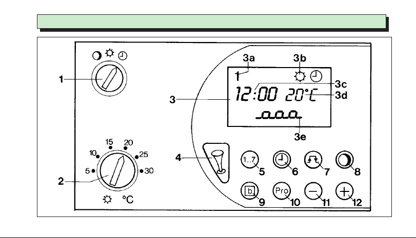
A Bedienungsanleitung
(Fig. 1, S. 3)
1 Betriebsartenschalter
zur Regelung auf
ständig Nachttemperatur bei
ständig Tagtemperatur bei
eingegebenem Heizprogramm bei
2 Tagtemperaturwähler
zur Einstellung der zur Heizzeit
gewünschten Raumtemperatur.
3 Display
mit Anzeige von Wochentag (3a), Betriebsart (3b),
Uhrzeit (3c), Raumtemperatur (3d), Heizzeiten (3e)
4 Party-Taste
zur Regelung auf Tagtemperatur
während der nächsten Absenkzeit
5 Wochentag-Taste 1..7
zur Eingabe des Wochentages
6 Uhrzeit-Taste
zur Eingabe der aktuellen Zeit und der
Schaltzeiten
7 Schaltpunkt-Taste
zum Anschauen und Programmieren
der Heiz- und Absenkzeiten
8 Nachttemperatur-Taste
zum Anschauen und Programmieren
der Nachttemperatur
9 Block-Taste b
zum gleichzeitigen Programmieren
mehrerer Wochentage bzw. Kopieren
eines Tagesheizprogrammes
10 Programmier-Taste Pro
zur Programmierung der durch die Tasten 5...9
eingegebenen Funktionen
11 Einstell-Taste –
zur Verkleinerung des eingestellten Wertes
12 Einstell-Taste +
zur Vergrößerung des eingestellten Wertes
Page 5
5
Inhalt - contents - nomenclature - inhoud - contenuto
D
GB
F
NL
I
int
D
F
NL
I
GB
Fig.
E
E
A Bedienungsanleitung Seiten 4...15
B Montageanleitung Seiten 16...21
A Operating instructions page 22...33
B Installations instructions page 34...39
A Mode d’emploi page 40...51
B Instructions d’installation page 52...57
A Bedieningsvoorschrift blz. 58...69
B Montagevoorschrift blz. 70...75
A Istruzioni d’uso pagina 76...87
B Istruzioni d’installazione pagina 88...93
A Instrucciones de uso Cap. 94...103
B y de instalación Cap. 104...111
C Abb., Fig., Af. Seite, side, page, blz., pag. 3, 112...127
Page 6
6
A Bedienungsanleitung – 1 Energiesparmöglichkeiten
1.1 Raumtemperatur begrenzen
Begrenzen Sie die Raumtemperatur auf den Wert, der
für Ihr Behaglichkeitsempfinden gerade ausreicht.
Jedes Grad darüber hinaus bedeutet einen unnötigen
Energieverbrauch von etwa 6%.
1.2 Raumtemperatur absenken
Senken Sie die Raumtemperatur für die Zeiten Ihrer
Nachtruhe und Abwesenheit ab.
1.3 Absenkzeiten ausdehnen
Die Heizung soll eine Stunde vor dem Zeitpunkt
einschalten, ab dem Sie die Wärme benötigen. Die
Heizung soll mindestens eine Stunde vor dem Zeitpunkt
abschalten, bis zu dem Sie es warm haben wollen.
Die Wärmeträgheit Ihres Gebäudes läßt die
Raumtemperatur nur allmählich absinken.
1.4 Lüften kurz aber kräftig
Öffnen Sie während der Heizperiode das Fenster nur
zum Lüften und nicht zur Temperaturregelung.
Eine kurze Stoßlüftung ist wirkungsvoller und energiesparender als lange offenstehende Kippfenster. Stellen
Sie während des Lüftens den Betriebsartenschalter (1)
auf , damit vermeiden Sie eine unnötige Heizungseinschaltung.
1.5 Raumtemperaturregler freihalten
Verdecken Sie Ihren Raumtemperaturregler nicht durch
Möbel, Vorhänge oder andere Gegenstände, damit er
ungehindert die zirkulierende Raumluft erfassen kann.
1.6 Heizkörperventile voll öffnen
Lassen Sie in dem Zimmer, in dem sich Ihr Raumtemperaturregler befindet, stets alle Heizkörperventile
voll geöffnet.
Page 7
7
A Bedienungsanleitung – 2 Betriebsart, Programmierung
(Fig. 1, 2)
2.1 Betriebsart einstellen
Mit dem Betriebsartenschalter (Fig. 2.1) können Sie die
Betriebsweise Ihrer Heizungsanlage Ihren Bedürfnissen
anpassen. Nach einer von Ihrem Gebäude und der
Außentemperatur abhängigen Zeit stellt sich allmählich
die gewünschte Raumtemperatur ein.
In Stellung wird die Raumtemperatur ständig ohne Berücksichtigung der Schaltuhr - nach der
Nachttemperatur (werkseitig auf 15°C eingestellt)
geregelt.
In Stellung wird die Raumtemperatur ständig
- ohne Berücksichtigung der Schaltuhr - nach dem am
Tagtemperaturwähler (2) eingestellten Wert geregelt.
In Stellung wird die Raumtemperatur selbsttätig
entsprechend dem nach Kap. 5 eingegebenen
Wochenheizprogramm geregelt.
2.2 Allgemeine Programmierhinweise
Mit der Taste Pro (10) wird der Programmierbetrieb
aktiviert. Im Display erscheint Pro (Fig. 2.2).
Von diesem Zustand aus können Sie die gewünschten
Einstellfunktionen aufrufen, indem Sie die zugehörigen
Funktionstasten (5...9) betätigen, z. B. Taste (6) für
die Uhrzeiteinstellung. Der Buchstabe p neben der
Einstellung zeigt an, daß Sie diese Werte ändern
können, siehe Fig. 2.3. Den Programmierbetrieb verlassen Sie, indem Sie die Taste Pro nach Ende der
Eingabe betätigen, die eingestellten Werte werden
damit übernommen. Falls Sie vergessen haben, diese
Taste Pro zu betätigen, schaltet der Raumtemperaturregler selbsttätig nach 5 Minuten auf Normalbetrieb
um. Im Normalbetrieb erkennen Sie auf der Anzeige:
Wochentag, Uhrzeit, Betriebszustand und Temperatur,
z. B. in Fig. 2.6:
5 5. Wochentag (Freitag)
Heizen nach „Tagtemperatur” bei
„Wochenheizprogramm”
19:58 aktuelle Uhrzeit: 19 Uhr, 58 Minuten
20 °C gemessene Raumtemperatur: 20 °C
D
Page 8
8
A Bedienungsanleitung – 3 Uhreinstellung
(Fig. 1, 3)
3.1 Uhrzeit ablesen
Im Display (3, Fig. 1) bedeuten:
1 1. Wochentag (Montag)
12:00 Aktuelle Uhrzeit: 12 Uhr und 0 Minuten
: blinkt, wenn die Schaltuhr läuft
20 °C Gemessene Raumtemperatur: 20 °C
3.2 Wochentag und Uhrzeit einstellen
Programmier-Taste Pro (10) drücken, der Raum-
temperaturregler schaltet in den Programmierbetrieb,
im Display (3) erscheint Pro (Fig . 3.1).
Uhrzeit-Taste (6) drücken im Display erscheint
die eingestellte Uhrzeit und ein p, in Fig. 3.2: 1,
12:00 p, das heißt Montag 12 Uhr,
Programmierbetrieb.
Wochentag-Taste 1..7 (5) drücken, sooft bis der
aktuelle Wochentag im Display (3a) steht, in Fig. 3.3:
5 (Freitag)
Mit der Einstell-Taste – (11) stellen Sie die Uhr
zurück.
Mit der Einstell-Taste + (12) stellen Sie die Uhr
vor, in Fig. 3.4 auf 19 Uhr und 58 Minuten.
Programmier-Taste Pro (10) drücken, damit
setzen Sie die Uhr mit der angezeigten Uhrzeit und 0
Sekunden in Gang. Im Display erscheint die
Normalanzeige, in Fig. 3.5:
5 5. Wochentag (Freitag)
Heizen nach „Tagtemperatur” bei
„Wochenheizprogramm”
19:58 aktuelle Uhrzeit: 19 Uhr, 58 Minuten
20 °C gemessene Raumtemperatur: 20 °C
Page 9

9
A Bedienungsanleitung – 4 Raumtemperaturen einstellen
(Fig. 1, 4)
4.1 Tagtemperatur wählen
Am Tagtemperaturwähler (Fig. 4.1) stellen Sie die
Raumtemperatur ein, die Ihnen während Ihres Aufenthalts im Wohnraum gerade ausreicht. Mit dieser
Tagtemperatur regelt Ihr Raumtemperaturregler dann
während der entsprechend Kap. 5 programmierten
Heizzeiten.
Empfehlung: Stellen Sie den Tagtemperaturwähler
zunächst zwischen 18...20 °C ein.
Bitte beachten: Der am Tagtemperaturwähler eingestellte Wert wird alle 30 Sekunden neu ausgewertet.
Dadurch können nach einer Verstellung des Tagtemperaturwählers max. 30 Sekunden vergehen, bis
die Veränderung wirksam wird.
4.2 Nachttemperatur anschauen
Nachttemperatur-Taste (3) drücken, im
Display erscheint die eingegebene Nachttemperatur
(Fig. 4.2). Sie ist werkseitig auf 15 °C programmiert.
Falls Sie diesen Temperaturwert ändern wollen,
verfahren Sie nach Kap. 4.3.
Eine der Tasten (5), (6), (9), (11) oder (12)
betätigen, im Display erscheint die Normalanzeige
(Fig. 4.6)
4.3 Nachttemperatur ändern
Die Raumtemperatur für die Absenkzeiten mit
„Nachttemperatur” stellen Sie so ein:
Programmier-Taste Pro (10) drücken, der
Raumtemperaturregler schaltet in den
Programmierbetrieb (Fig. 4.3).
Nachttemperatur-Taste (8) betätigen, im
Display erscheint ein p vor der eingestellten
„Nachttemperatur” (Fig. 4.4).
Mit der Einstell-Taste + (12) erhöhen Sie die
„Nachttemperatur” bis maximal 20 °C (in Fig. 4.5 auf
17 °C).
Mit der Einstell-Taste – (11) verringern Sie die
„Nachttemperatur” bis minimal 5 °C.
Programmier-Taste Pro drücken, damit gehen
Sie in den Regelbetrieb (Fig. 4.6).
D
Page 10
10
A Bedienungsanleitung – 5 Heizzeiten programmieren
(Fig. 1, 5)
5.1 Darstellung der Heizzeiten
Sie können für Ihren Raumtemperaturregler bis zu drei
Heizzeiten pro Tag eingeben. Dabei müssen Sie
lediglich den Zeitpunkt für den Beginn und das Ende
der jeweiligen Heizzeit einstellen. Die Heizzeiten
können Sie für jeden Wochentag unterschiedlich
programmieren. Die zeitliche Abfolge der Heizzeiten,
das Tagesprofil, wird im Display (3e, Fig. 1) symbolisch dargestellt. Dabei kennzeichnen die oberen
waagerechten Segmente die Heizzeiten, die unteren
die Absenkzeiten. Die senkrechten Segmente stellen
die Schaltpunkte dar. Eine Heizzeit besteht somit aus
einem senkrechten Segment für den Beginn der Heizzeit (Fig. 5.1), dem oberen waagerechten Segment für
die Dauer der Heizzeit und dem senkrechten Segment
für das Ende der Heizzeit (Fig. 5.2). Wollen Sie z. B.
von 6:00 bis 22:00 Uhr heizen, benötigen Sie nur
eine Heizzeit. Gelöschte Heizzeiten sind durch senkrechten Strich dargestellt (Fig. 5.3).
5.2 Heizzeiten anschauen
Schaltpunkt-Taste (7) drücken, im Display
erscheint das Tagesprofil des angezeigten Wochentages (Fig. 5.1). Zunächst wird die zu dem blinkenden
Segment gehörende Schaltzeit angezeigt in Fig. 5.1
der Beginn der Heizzeit am 5. Wochentag (Freitag)
um 6:00 Uhr.
Schaltpunkt-Taste (7) erneut betätigen,
im Display erscheint die Uhrzeit des nächsten Schaltpunktes (blinkt) in Fig. 5.2 das Ende der ersten
Heizzeit um 22:00 Uhr.
Wochentag-Taste 1..7 (5) drücken, damit
können Sie die Heizzeiten eines anderen Wochentages, z. B. für Sonntag (Fig. 5.4), ansehen. Falls Sie
diese ändern wollen, können Sie die Heizzeiten nach
Kap. 5.4 einstellen.
Eine der Tasten (6), (8), (9), (11) oder (12)
betätigen, im Display erscheint die Normalanzeige
(Fig. 5.5).
Page 11
11
A Bedienungsanleitung – 5 Heizzeiten programmieren
(Fig. 1, 5)
5.3 Grundprogramm
Falls Sie keine Änderung der Schaltzeiten vornehmen,
arbeitet der Raumtemperaturregler nach dem werkseitigen Grundprogramm:
Heizzeit mit Tagtemperatur: 06:00 bis 22:00
Absenkzeit mit Nachttemperatur: 22:00 bis 06:00
Nachttemperatur: 15°C
Der Raumtemperaturregler VRT-PZA regelt also bei
werkseitiger Voreinstellung die Raumtemperatur an
jedem der sieben Wochentage zwischen 6:00 und
22:00 Uhr auf den am Tagtemperaturwähler eingestellten Wert (siehe Kap. 4.1). In der Zwischenzeit von
22:00 bis 6:00 Uhr regelt er die Raumtemperatur auf
die Nachttemperatur von 15 °C (Kap. 4.2).
Diese Grundeinstellung ermöglicht bereits nach
Einstellung der Uhrzeit einen sinnvollen Regelbetrieb.
5.4 Heizzeiten eingeben
Sie können anstelle des Grundprogrammes individuelle
Heizzeiten eingeben:
Programmier-Taste Pro (10) drücken der
Raumtemperaturregler schaltet in den Programmierbetrieb (Fig. 5.6).
Schaltpunkt-Taste (7) drücken, die für den
angezeigten Tag programmierten Heizzeiten erscheinen im Display (Fig. 5.7). Das blinkende Segment stellt
den Schaltpunkt für den Beginn der ersten Heizzeit
dar.
Wochentag-Taste 1..7 (5) drücken bis im Display
der zu programmierende Wochentag erscheint, hier 7
- Sonntag - (Fig. 5.8). Die Uhrzeit für den blinkenden
Schaltpunkt können Sie (z. B. auf den in Fig. 5.9 dargestellten Wert) folgendermaßen einstellen:
Mit der Einstell-Taste – (11) stellen Sie den Zeitpunkt in 10-Minuten-Schritten zurück.
Mit der Einstell-Taste + (12) stellen Sie den Zeitpunkt in 10-Minuten-Schritten vor.
D
Page 12
12
A Bedienungsanleitung – 5 Heizzeiten programmieren
(Fig. 1, 5)
Durch längere Betätigung einer der Einstelltasten erfolgt
eine schnellere Zeitverstellung, zunächst in 10-MinutenSchritten, bei längerer Betätigung in 1-StundenSchritten.
Schaltpunkt-Taste (7) betätigen, bis der zu
verstellende Schaltpunkt blinkt (Fig. 5.10). Schaltpunkt,
wie beschrieben, verändern (Fig. 5.11).
Programmier-Taste Pro (10) drücken, damit
wird die Programmierung übernommen, im Display
erscheint die Normalanzeige (Fig. 5.5).
5.5 Beispiel für die Heizzeiteingabe
Aktueller Wochentag ist Freitag. Eingestellt ist das
Grundprogamm. Ihr Wunsch:
Sonntag: Heizzeit von 5:00 bis 9:00 Uhr
Programmier-Taste Pro drücken (Fig. 5.12)
Schaltpunkt-Taste betätigen (Fig. 5.13)
Wochentag-Taste1...7 2x betätigen (Fig. 5.14).
Einstell-Taste – betätigen bis 5:00 (Fig. 5.15)
Schaltpunkt-Taste betätigen (Fig. 5.16)
Einstell-Taste – betätigen bis 9:00 (Fig. 5.17)
Programmier-Taste Pro drücken, der Raum-
temperaturregler geht mit den veränderten Werten
in Betrieb. Im Display erscheint die Normalanzeige
(Fig. 5.5).
5.6 Löschen einer Heizzeit
Der Raumtemperaturregler berücksichtigt Heizzeiten
nicht, bei denen der Anfang und das Ende auf die
gleiche Zeit eingestellt sind. Der Absenkbetrieb wird
fortgesetzt. Im Display wird nur ein senkrechtes
Segment für den jeweiligen Schaltpunkt angezeigt
(Fig. 5.18). Um aus einer gelöschten Heizzeit wieder
eine wirksame Heizzeit zu machen, reicht es aus,
wenn Sie den Beginn der Heizzeit auf eine frühere
bzw. das Ende auf eine spätere Heizzeit einstellen.
Die Einstellung der wieder wirksamen Heizzeit kann
entsprechend Kap. 5.4 vorgenommen werden.
Page 13

13
A Bedienungsanleitung – 5 Heizzeiten programmieren
(Fig. 1, 5)
5.7 Heizzeiten für mehrereWochentage
programmieren bzw. kopieren
Sie können für mehrere Wochentage gleichzeitig Heizzeiten eingeben bzw. vorhandene Tages-Heizzeiten
auf einen oder mehrere Wochentage kopieren:
Programmier-Taste Pro (10) drücken, der
Raumtemperaturregler schaltet in den Programmierbetrieb (Fig. 5.19).
Schaltpunkt-Taste (7) betätigen, der verstell-
bare Schaltpunkt blinkt (Fig. 5.20).
Wochentag-Taste 1..7 (5) drücken, bis im
Display der Wochentag erscheint, dessen Heizzeiten
Sie übertragen möchten.
Block-Taste b (9) drücken, damit wird dieser Tag
als Quelltag festgelegt. Es erscheint cP (Fig. 5.20).
Wochentag-Taste 1..7 (5) drücken, damit
können Sie weitere Wochentage auswählen für die Sie
durch Betätigen der Block Taste b (9) gemeinsame
Heizzeiten übernehmen. Im Display werden für die
zum Block mit gemeinsamen Heizzeiten gehörenden
Wochentage feste Ziffern angezeigt, die Ziffer des
angewählten Tages blinkt (Fig. 5.21).
Soll ein Wochentag wieder aus dem Block herausgenommen werden:
Wochentag-Taste 1..7 (5) so oft drücken bis
die Ziffer des entsprechenden Wochentages blinkt
(Fig. 5.22).
Block-Taste b (9) betätigen, im Display wird b
gelöscht (Fig. 5.23).
Programmier-Taste Pro (10) drücken, die
Programmierung wird übernommen, die Normalanzeige im Display erscheint (Fig. 5.24).
D
Page 14

14
A Bedienungsanleitung – 6 Sonderfunktionen
(Fig. 1, 6)
6.1 Party-Funktion
Diese Funktion läßt sich nur bei Regelung nach Heizprogramm aktivieren.
Party-Taste , (4) drücken, im Display erscheint das
Symbol für Partybetrieb (Fig. 6.1). Dann wird auch
während der folgenden bzw. laufenden Absenkzeit
auf die eingestellte Tagtemperatur geregelt. Mit Beginn
der nächsten Heizzeit endet der „Partybetrieb”, das
Symbol erlischt.
Der Regler arbeitet jetzt wieder nach dem eingestellten
Heizprogramm.
Zum Abschalten der Party-Funktion die Party-Taste
erneut drücken, das Symbol erlischt.
6.2 Sommerbetrieb, Frostschutz
Soll lediglich während der Nacht eine zu starke
Auskühlung vermieden werden, brauchen Sie das
eingegebene Heizprogramm nicht zu ändern sondern
nur den Betriebsartenschalter (1) auf Stellung
drehen.
6.3 Betrieb bei Netzausfall
Bei Stromausfall läuft die Schaltuhr Ihres Raumtemperaturreglers über einen Kondensator einige Zeit
weiter (Gangreserve), das Wochenheizprogramm
bleibt erhalten. Alle Funktionen des Raumtemperaturreglers bleiben während dieser Zeit erhalten.
Bei Wiederkehr der Netzspannung läuft das Heizprogramm automatisch weiter.
6.4 Betrieb bei längerem Netzausfall
Bei längerem Spannungsausfall, der zur völligen Entleerung des Kondensators führt, werden eingegebene
Heizzeiten weiter gespeichert. Bei Wiederkehr der
Netzspannung muß dann nur noch Wochentag und
Uhrzeit aktualisiert werden, wie in Kap. 3 beschrieben.
Der Kondensator für die Gangreserve lädt sich selbsttätig wieder auf.
Page 15
15
A Bedienungsanleitung – 7 Vorlauftemperatur
Einstellung am Vaillant Thermoblock
Stellen Sie den Vorlauftemperaturregler an Ihrem
Vaillant Thermoblock entsprechend nachstehender
Empfehlung ein:
Bei Heizungsanlagen im Niedertemperaturbereich mit
Vorlauftemperaturen bis max. 75°C:
Stellung 7.
Bei Heizungsanlagen mit Vorlauftemperaturen bis
max. 90 °C:
Stellung 9.
D
Page 16
16
B Montageanleitung – 8 Montage
8.1 Vorsichtshinweis
Die Montage, der elektrische Anschluß, die Einstellungen im Gerät sowie die Erstinbetriebnahme sollen
nur durch einen anerkannten Fachhandwerksbetrieb
vorgenommen werden.
8.2 Einsatzbereich
Der Raumtemperaturregler VRT-PZA läßt sich problemlos an alle Vaillant Thermoblocks VC...bzw. VCW...
mit 15...24 V-Reglereingang (Klemmen 7, 8, 9)
anschließen. Ausführliche Informationen enthalten die
Vaillant Planungsunterlagen. Die Montageplatte läßt
sich auf die vorhandenen Befestigungslöcher eines
Vaillant Raumtemperaturreglers früherer Bauart
anschließen, aber auch anstelle eines Raumtemperaturreglers anderer Hersteller mit dem Befestigungsstichmaß 48...60 x 60...65 mm. Der Raumtemperaturregler VRT-PZA ist werkseitig als Zweipunktregler
eingestellt. Er kann vom Fachhandwerksbetrieb auf
analoge (stetige) Regelung umgestellt werden, wie in
Kap. 10.2 beschrieben.
8.3 Pumpenschaltung
Die Betriebsart „weiterlaufende Pumpe” beim Thermoblock ist nach Anschluß des Raumtemperaturreglers
VRT-PZA nicht mehr möglich. Wird die Pumpe auf
diese Betriebsart eingestellt, so ergibt sich aus funktionstechnischen Gründen automatisch die Betriebsart
„durchlaufende Pumpe”. Stellen Sie den PumpenBetriebsartenschalter auf „s” oder „II”.
8.4 Funk-Entstörung
Der Raumtemperaturregler ist gemäß VDE 0875 nach
Funkstörgrad „N” entstört. Wird er mit anderen
Geräten in einer Anlage verwendet, so hält dieser in
der Regel den Funkstörgrad „N” ein, wenn auch alle
übrigen Betriebsmittel den Funkstörgrad „N” einhalten.
Page 17

17
B Montageanleitung – 8 Montage
(Fig. 7)
8.5 Montageort
Der Raumtemperaturregler ist an einem für seine
Funktion geeigneten Ort anzubringen. Der günstigste
Montageort ist meistens im Hauptwohnraum an einer
Innenwand in ca. 1,5 m Höhe.
Dort soll der Raumtemperaturregler die zirkulierende
Raumluft - ungehindert von Möbeln, Vorhängen oder
sonstigen Gegenständen - erfassen können.
Der Anbringungsort soll so gewählt werden, daß
weder die Zugluft von Tür oder Fenster noch Wärmequellen wie Heizkörper, Kaminwand, Fernsehgerät
oder Sonnenstrahlen den Raumtemperaturregler direkt
beeinflussen können. Im Zimmer, in dem der Raumtemperaturregler angebracht ist, müssen alle Heizkörperventile stets voll geöffnet sein.
8.6 Montagefolge
Die elektrischen Leitungen zum Thermoblock werden
zweckmäßigerweise schon vor Anbringen des
Raumtemperaturregler-Oberteils (7) verlegt. Die
Befestigung wird folgendermaßen vorgenommen:
a) Den Hauptschalter des Thermoblocks auf „0”
stellen.
b) Eine Schraubendreherspitze in die Haltenocken (8)
leicht eindrücken und damit das Raumtemperaturregler-Oberteil von der Montageplatte (9)
abnehmen.
c) Zwei Befestigungsbohrungen (10) mit Ø 6 mm
entsprechend, Fig. 7, anbringen und die mitgelieferten Dübel einsetzen.
d) Montageplatte mit den beiden mitgelieferten
Schrauben an der Wand befestigen.
D
Page 18

18
B Montageanleitung – 9 Elektro-Anschluß
(Fig. 8, 9, 10)
Anschluß am Thermoblock
Bitte beachten: Der Raumtemperaturregler VRT-PZA
darf nur an die Kleinspannungsklemmen 7, 8, 9 eines
Vaillant Thermoblocks angeschlossen werden. Der
elektrische Anschluß soll von einem anerkannten
Fachhandwerksbetrieb vorgenommen werden. Die
Anschlußverdrahtung an die Klemmen 7, 8, 9 eines
Vaillant Thermoblocks VC... bzw. VCW... ist entsprechend Fig. 9 vorzunehmen.
Das Anschlußkabel durch die Kabeldurchführung (11),
legen.
Nach Anschluß an die Klemmleiste (12) den
Raumtemperaturregler auf die Montageplatte so aufsetzen, daß die Steckmesser (12b; Fig. 10) in die
Kontakte (12a) gesteckt werden. Den Raumtemperaturregler auf die Montageplatte aufdrücken und
einrasten.
Den Hauptschalter des Thermoblocks auf „I” stellen.
Page 19

19
B Montageanleitung – 10 Inbetriebnahme
(Fig. 10)
10.1 Erstinbetriebnahme
Die erste Inbetriebnahme des Raumtemperaturreglers
gemeinsam mit der Heizungsanlage sowie die erste
Eingabe entsprechend den Wünschen des Benutzers
soll von einem anerkannten Fachhandwerksbetrieb
vorgenommen werden, der die Verantwortung für die
Installation übernommen hat.
Dabei sind folgende Nähere
Maßnahmen durchzuführen Hinweise
Energiesparmöglichkeiten Kap. 1
Wochentag und Zeit einstellen Kap. 3
Heizzeiten eingeben Kap. 5
Funktionen prüfen Kap. 6
Vorlauftemperatur einstellen Kap. 7
10.2 Zweipunkt-/Analog
(Stetig)-Regelung
Werkseitig regelt der VRT-PZA im Zweipunktbetrieb.
Die Umstellung ist durch den Fachhandwerksbetrieb
möglich:
Hauptschalter des Thermoblocks auf „0” stellen
Raumtemperaturregler-Oberteil von der Montageplatte
entspr. Kap. 8.6 abnehmen.
Wenn die Leistung des Thermoblocks, z. B. um eine
größere Warmwasserleistung zu erzielen deutlich über
dem errechneten Wärmebedarf liegt, soll der
Zweipunkt-/Analog-Umschaltstecker (14) auf Stellung
PZ gesteckt werden.
In Anlagen, bei denen die Heizleistung dem errechneten Wärmebedarf angepaßt ist, empfiehlt sich die
Umschaltung auf Analog (Stetig)-Regelung. Dazu wird
der Zweipunkt-/Analog-Umschaltstecker (14) auf
Stellung PA gesteckt.
D
Page 20
20
B Montageanleitung – 10 Inbetriebnahme
(Fig. 10)
10.3 12-/24-Stunden-Anzeige
Die Umstellung ist durch den Fachhandwerksbetrieb
möglich:
Hauptschalter des Thermoblocks auf „0” stellen,
Raumtemperaturregler-Oberteil von der Montageplatte
entspr. Kap. 8.6 abnehmen.
Wird vom Benutzer eine 24-Stunden-Anzeige im
Display (3, Fig. 1) gewünscht, so ist der 12-/24Stunden-Umschaltstecker (15, Fig. 10) auf 24 h zu
stecken.
Wird vom Benutzer eine 12-Stunden-Anzeige im
Display (3, Fig. 1) gewünscht, so ist der 12-/24Stunden-Umschaltstecker (15) auf 12 h zu stecken.
Die Anzeige im Display schaltet nach längstens
30 Sekunden auf den neuen Anzeigemodus um.
10.4 Betriebsbereitstellung
Nach jeder dieser Einstellungen den Raumtemperaturregler auf die Montageplatte aufsetzen und den
Hauptschalter des Thermoblocks auf „I” stellen.
Mit der CE-Kennzeichnung wird dokumentiert, daß die VRT die
grundlegenden Anforderungen der Gasgeräterichtlinie
(Richtlinie 90/396/EWG des Rates) und die grundlegenden
Anforderungen der Richtlinie über die elektromagnetische
Verträglichkeit (Richtlinie 89/336/EWG des Rates) erfüllen.
Page 21
21
11 Technische Daten
Gerätetyp VRT-PZA
Art.-Nr. 9148
Betriebsspannung vom VC bzw. VCW 15...24 VStromaufnahme Ɱ30 mA
Temperatur-Einstellbereich Tagtemperatur 5...30°C
Nachttemperatur 5...20°C
Mögliche Heizzeiten 3 pro Tag
Proportionalbereich 2 K
Schaltdifferenz 1 K
Erfassung der Ist-/Solltemperatur alle 30 s
Gangreserve 10 min
Abmessungen Breite 148 mm
Höhe 85 mm
Tiefe 30 mm
Gewicht ca. 200 g
Anschlußleitungen 3 x 0,75 mm
Schutzart IP 30
Schutzklasse III
Betriebstemperatur +5...+40 °C
Zul. Lagertemperatur -20...+50 °C
Änderungen vorbehalten
D
Page 22
22
A Operating instructions
(Fig. 1, p. 3)
1 Operating mode switch
For control at
constantly night-time in position
constantly daytime temperature in position
entered heating programme in position
2 Temperature selector
For setting the required room temperature
3 Display
With reading of the day of the week (3a),
the operating mode (3b) the time (3c), the room
temperature (3d), the heating periods (3e)
4 Party key
For control at daytime temperature
5 Day key
For entering the day of the week
6 Time key
For entering the current time and the changeover times
7 Change-over key
For indicatlng and programming the heating periods
and the drop periods
8 Night-time temperature key
For indicating and programming the night-time
temperature
9 Block key
For simultaneously programming several days or for
copying a 24-h programme
10 Programming key
For programming the operations entered by the keys
5...9
11 Setting key –
For lowering the set value
12 Setting key +
For increasing the set value
Page 23

23
A Operating instructions – 1 Application
(Fig. 1, p. 3)
1.1 Operating conditions
With the room thermostat VRT-PZA, the temperature for
the heating periods „day” and the drop periods
„night” can be controlled independently of each other.
From the beginning to the end of a heating period, the
room is controlled at the „daytime temperature” set by
you. Between these heating periods, i. e., during the
drop periods, the room thermostat VRT-PZA controls
the room temperature at the „night-time temperature”
set by you.
Heating periods can be programmed individually for
every day and together for several days. In addition,
the factory-set basic programme can be readjusted at
any time.
With the party key (4), it is possible to continue the
heating operation during the following drop period
even if the current heating period is terminated. If, for
example, the party key was pressed during the last
heating period of a day, the heating system continues
operating at day-time temperature until the end of the
first heating period of the following day.
GB
Page 24
24
A Operating instructions – 1 Application
(Fig. 1, p. 3)
1.2 Possibilities for energy saving
Limiting the room temperature
Limit the room temperature to the minimum value at
which you still feel comfortable. Every degree above
this represents an unnecessary additional consumption
of energy by about 6%.
Lowering the room temperature
Lower the room temperation during the night or
periods of absence.
Extending the drop periods
The heating system is to start on hour before you will
have a demand of heat. The heating system is to shut
down at least one hour in advance of the time up to
which you would like to keep it warm. Due to the
hermal inertia of the building, the room temperature
will only drop gradually.
Ventilate briefly but thoroughly
During the heating period, open windows only for
airing and not for regulating the room temperature.
A brief but vigorous airing is more effective and more
economical than keeping windows slightly ajar for
longer periods. When airing, set the operating mode
switch (1) to , this will prevent your heating system
from switching on unnecessanly.
Keep the room thermostat clear
Do not obstruct your room thermostat with furniture,
curtains or other objects so that its sensor is fully exposed to the circulating room air.
Fully open the radiator valves
Always keep fully open all radiator valves in the room
in which your room thermostat is situated.
Page 25
25
A Operating instructions – 2 Operating mode - notes on programming
(Fig. 1, 2)
2.1 Setting the operating mode
With the operating mode switch (2, fig. 1), you can
adapt the operating mode of your heating system
according to your personal needs. After a period of
time determined by the inertia of the building and the
outside temperature, the required room temperature is
adjusted.
In position , the room temperature is kept constant
at the night-time temperature (factoryset to 15ºC) without considering the timer.
In position , the room temperature is kept constant
according to the value set at the temperature selector
(2) - without considering the timer.
In position , the room temperature is automatically
controlled according to the entered heating
programme (chap. 5).
2.2 General notes on programming
The programming mode is started by pressing the Pro
key (10). The display shows Pro (fig. 2.2) now it is
possible to indicate the required setting by pressing the
respective operation keys (5-9), for example, key (6)
for setting the time. The letter p next to the setting
indicates that these values can be altered, see fig. 2.3.
Exit the programming mode after entering the values
by pressing the Pro key - thus, the set values are
adopted. If you forget to press this Pro key, the room
thermostat will automatically change to normal
operation after 5 minutes. In normal operation, the
reading shows: day of the week, time, temperature
and operating mode, for example in fig. 2.6:
5 5. day of the week (Friday)
Heating according to 7-day programme
19:58 Actual time: 7 p. m. and 58 minutes
20°C Measured room temperature 20°C
GB
Page 26
26
A Operating instructions – 3 Setting the timer
(Fig. 1, 3)
3.1 Reading the time
Description of display (3, fig. 1):
1 1. day of the week (Monday)
12:00 Actual time
Flashes when the timer runs
20°C Measured room temperature 20 °C
3.2 Setting the day of the week
and the time
Press Pro programming key (10), the room
thermostat changes to the programming mode; the
display (3) shows Pro (fig. 3.1).
Press time-key (6), the display shows the set time
and a p, in fig. 3.2: 1, 12:00 p, i.e. Monday,
12.00 a.m., programming mode.
Press (5) day-key 1...7 until the current day of the
week is indicated on the display (3a), in fig. 3.4: 5
(Friday)
With the setting key – (11), the timer is set back.
With the setting key + (12), the timer is put
forward, in fig. 3.4 to 7 p.m. and 58 minutes.
Press Pro programming key (10) in order to start
the timer with the indicated time and 0 seconds. The
display shows the normal reading, in fig. 3.5:
5 5. day of the week (Friday)
Heating at „daytime temperature“ with
operating mode „Heating according to
7-day programme“
19:58 current time: 7 p. m. and 58 minutes
20°C Measured room temperature 20°C
Page 27

27
A Operating instructions – 4 Setting the room temperatures
(Fig. 1, 4)
4.1 Selecting the daytime temperature
With the temperature selector (fig. 4.1), set the room
temperature at which you still feel comfortable in your
living room. Every degree above this represents an unnecessary additional consumption of fuel by about 6%.
According to this daytime temperature, your room thermostat then controls the room temperature during the
heating periods programmed according to chapter 5.
Recommendation: Set the temperature selector (2)
initially to 18 to 18°C...20°C.
4.2 Indicating the night-time
temperature
Press night-time temperature key (8), the
display shows the entered night-time temperature
(fig. 4.2) which is factory-set to 15°C. If this value is to
be altered, proceed according to chapter 4.3.
Press one of the keys (5), (6), (9), (11) or (12), the
display indicates the normal reading.
4.3 Altering the night-time temperature
Set the room temperature for the drop periods with
„night-time temperature“ as follows:
Press Pro programming key (10), the room ther-
mostat changes to the programming mode (fig. 4.3).
Press night-time temperature key (8), the
displays shows a p before the set „night-timetemperature“ (fig. 4.4).
The night-time temperature can be increased up to
max. 20°C with the setting key + (in fig. 4.5 to
17°C).
The „night-time temperature“ can be decreased to
min. 5°C with the setting key –
Press Pro programming key for changing to
control mode (fig. 4.6).
GB
Page 28
28
A Operating instructions – 5 Programming heating periods
(Fig. 1, p. 3, 5)
5.1 Indicating the heating programme
Up to three heating periods per day can be entered in
your room thermostat. It is only necessary to set the
time for the beginning and the end of the respective
heating periods. The heating periods can be
programmed differently for every day of the week.
The chronological sequence of the heating periods, the
24-h programme, is indicated with symbols on the
display (3e, fig. 1). The upper horizontal segments
represent the heating periods, the lower segments the
drop periods. The vertical segments represent the
changeover points. Thus, one heating period consists
of a vertical segment for the beginning of the heating
period (fig. 5.1), the upper horizontal segment for the
duration of the heating period and of a vertical
segment for the end of a heating period (fig. 5.2). For
a heating period between 6.00 a.m. to 10.00 p.m.,
only one heating period is necessary. Deleted heating
periods are marked by a line (fig. 5.3).
5.2 Indicate the heating programme
Press change-over key (7), the display shows
the 24-hours programme of the indicated day of the
week (fig. 5.1). Then, the change-over time of the
flashing segment is shown, in fig. 5.1 the beginning of
the first heating period on the 5. day of the week
(Friday) at 6.00 a.m.
Press again change-over key (7), the display
shows the time of the next change-over point (flashing), in fig. 5.2 the end of the first heating period at
10.00 p.m.
Press day key 1..7 (5) to examine the heating
periods of another day, for example Sunday (fig. 5.4).
In case of altering, set these heating periods according
to chapter 5.4
Press one ofthe keys (6), (8), (9), (11) or (12), the
display shows the normal reading (fig. 5.5).
Page 29
29
A Operating instructions – 5 Programming heating periods
(Fig. 1, 5)
5.3 Basic programme
If the change-over times are not altered, the room
thermostat operates according to the factory-set basic
programme:
Heating period with daytime temperature:
6.00 a.m....10.00 p.m.
Drop period with night-time temperature:
10.00 p.m....6.00 a.m.
Night-time temperature: 15°C.
On each of the seven days of the week between
6.00 a.m. tp 10.00 p.m. the factory-set room
thermostat VRT-P2D controls the room temperature to
the value set at the temperature selector (see chapter
4.1). In the meantime, from 10.00 p.m. to 6.00 a.m.,
the thermostat sets the room temperature to the nighttime temperature of 15°C (chapter 4.2).
Thus, it is already possible sensibly to control the
temperature after setting the time.
5.4 Entering heating periods
It is possible to enter different heating periods Iinstead
of the basic programme:
Press Pro programming key (10), the room
thermostat changes to the programmingmode (fig. 5.6).
Press change-over key (7), the heating
periods entered for the indicated day are shown in the
display (fig. 5.7). The flashing segment represents the
change-over time for the beginning of the first heating
puriod.
Press day key 1...7 (5) until the day of the week to
be programmed is displayed, here7 (Sunday)(fig. 5.8).
The time for the flashing change-over point can be set
as follows (e.g. to the value shown in fig. 5.9):
With the setting key – (11), the time is set back in
10-min. steps.
With the setting key + (12), the time is put
forward in 10-min. steps.
GB
Page 30
30
A Operating instructions – 5 Programming heating periods
(Fig. 1, 5)
By pressing the + or – key without interruption,
the time is altered rapidly, first in 10-min. steps. then in
1-hour steps.
Press change-over key (7) until the changeover point to be altered flashes (fig. 5.10).
Proceed to altering as described (fig. 5.11).
Press Pro programming key (19) for adopting
the programmed time, the display shows the normal
reading (fig. 5.6):
5.5 Example for entering the heating
period
The current day is Friday. The basic programme is
preset. Your wish:
Sunday: Heating period from 5.00 a.m. to 9.00 a.m.
Press Pro programming key (fig. 5.12),
Press change-over key (Fig. 5.13),
Press day key 1..7 twice (Fig. 5.14),
Press setting key – until 5:00 (fig. 5.15) appears.
Press change-over key (fig. 5.16)
Press setting key + until 9:00 (fig. 5.17) appears.
Press Pro programming key, the room
thermostat starts operating with the altered values
(fig. 5.5).
5.6 Deleting a heating period
The thermostat does not consider heating periods set to
the same time for the beginning and the end of a
period. The drop period is continued. The display only
shows a vertical segment for the respective changeover point (fig. 5.18). To reactivate a deleted heating
period, it is sufficient to set the beginning of the
heating period to an earlier heating period or the end
to a later one resp. For this, prolong the deleted
heating period. The active heating period can be set
according to chapter 5.4.
Page 31

31
A Operating instructions – 5 Programming heating periods
(Fig. 1, 5)
5.7 Simultaneously programming
or copying resp. heating periods
for several days
Heating periods can be entered simultaneously for
several days of the week, or existing heating periods
for one day can be copied to one or several days.
Press Pro programming key (10), the room
thermostat changes to the programming mode
(fig. 5.19).
Press change-over key (7), the adjustable
change-over point flashes (fig. 5.20).
Press day key 1..7 (5) until the day with the
heating periods to be copied is displayed.
Press block key b (9) for fixing this day as source
day. cP is displayed (fig. 5.20).
Press day key 1..7 (5) to select further days for
which hoint heating periods are copied b pressing the
block key b (9). The display shows fixed numbers for
the days of the block with joint flashes (fig 5.21).
If one day is to be removed:
Press day key 1..7 (5) until the number of the
corresponding dav flashes (5.22).
Press block key b (9); the b in the display is
deleted (fig. 5.23).
Press Pro programming key (10), the
programme is adopted, the display shows the normal
reading (fig. 5.5).
GB
Page 32

32
B Installations instructions – 6 Special operating conditions
(Fig. 1, 6)
6.1 Party operation
This operating condition can only be activated if the
temperatures are controlled according to a heating
programme.
Press party key (4), the display shows the symbol
for party operation (fig. 6.1). In this case, the
thermostat is controlled at the set daytime temperature
even during the following or current drop period resp.
The „party operation“ is finished at the beginning of
the next heating period, the symbol disappears.
Then, the thermostat operates again according to the
entered heating programme.
Press party key again for terminating the party
operation. The symbol , disappears.
6.2 Summertime operation,
frost protection
If the rooms should not cool down too much over night,
you do not have to change the selected heating
programme, but only turn the operating mode switch
(1) to position .
6.3 Operation in the case of a power
failure
In the case of a power failure, the timer of your room
thermostat continues operating by means of a
capacitor for some time (power reserve)., the 7-day
heating programme is maintained.
All operating modes of the room thermostat are
preserved during this period. After the mains current is
re-estabished, the heating programme continues
automatically.
6.4 Operation in the case of a
long-term power failure
In the case of long-term power failures causing the
complete discharge of the capacitor, the entered
heating periods are preserved. After the mains current
returns, it is only necessary to update the weekday and
the time of day as described in chapter 3.
The capacitor for the power reserve is recharged
automatically.
Page 33

33
B Installations instructions – 7 Setting the flow temperature
Set the flow thermostat at your Vaillant
THERMOcompact/COMBlcompact according to the
below-mentioned recommendation:
In the case of heating installations at low temperatures
with flow temperatures up to max 75°C:
position 7.
In the case of heating installations with flow
temperatures up to max 90°C:
position 9.
GB
Page 34

34
B Installations instructions – 8 Installation
(Fig. 7)
8.1 Warning
The installation, electrical connection, settings in the
appliance as well as the initial taking into operation
shall only be carried out by an authorized installer.
8.2 Possible use
The room thermostat VRT-PZA can be connected
without difficulty to all Vaillant THERMOcompact/
COMBlcompact appliances VR... or VCW... with 24-V
thermostat input (terminals 7, 8, 9).
The mounting plate may be connected to the already
existing connections of a former type of Vaillant room
thermostats or even replace a room thermostat built
by another manufactorer with the 48...60 x 66...65
gauge.
The room thermostat VRT-PZA is factory-set to on/off
control. The setting may be changed by your
authorized installer to analog (continous) control as
described in chapter 10.2. It is not necessary to
change the electrical connections.
8.3 Pump setting
After the connection of the room thermostat VRT-PZA,
the pump cannot be operated „continously“ any longer.
If the pump is set to this mode, it will automatically
operate in the mode „permanent running“ for
functional reasons. Set the pump selector to „s“ or „II“.
8.4 Interference suppression
The room thermostat is interference-suppressed according to VDE 0875 with the suppression factor „N“.
In case it is used with other appliances together in one
installation, this suppression factor „N“ will be generally met provided that all other devices are factor „N“
interference-suppressed.
Page 35

35
B Installations instructions – 8 Istallation
(Fig. 7)
8.5 Positioning
The room thermostat must be installed in a position
which ensures a correct functioning. Generally, the
most suitable installation site is in the main living room,
at a height of 1.5 m. There, the room thermostat
is to be exposed to the circulating room aire without
obstruction by furniture curtains or other objects.
The room thermostat must be positioned so as to
ensure that neither draughts from windows or doors
not heat sources such as radiators, chimney breasts,
TV sets or sunlight can directly affect the room
thermostat. In the room in which the room thermostat is
installed, all radiator valves must always be fully open.
GB
8.6 Installation sequence
We recommend to install the connecting cable to the
THERMOcompact/COMBlcompact before mounting
the front casing of the room thermostat. To fix it,
proceed as follows:
a) Take off the front casing (1) of the room thermostat
by means of a screw driver, removing it out of the
retaining cams (3) on the mounting plate (2).
b) Drill two holes with a diameter of 6 mm as shown in
figure 8 and insert the attached plugs.
c) Fix the mounting plate to the wall with the two
supplied screws.
Page 36

36
A Installations instructions – 9 Electrical connection
(Fig. 8, 9, 10)
Connection to the
THERMOcompact/COMBlcompact
Please note:
The room thermostat VRT-PZA must only be connected
to the low-voltage terminals 7, 8, 9 of a Vaillant
THERMOcompact/COMBlcompact. The electrical
connection must be carried out by an authorized
installer. The connection to the terminals 7, 8, 9 of a
Vaillant THERMOcompact/COMBlcompact VC... or
VCW... is to be effected according to chap. 9.
The connection cable is introduced in the cable entry
(11).
After connecting the room thermostat to the
terminal strip (12), place it on the mounting plate
so that the blades (12b, fig. 1) are plugged into the
contacts (12a). Place the room thermostat on the
mounting plate and engage it. Set the main switch of
the THERMOcompact/COMBlcompact to „I“.
Page 37

37
B Installations instructions – 10 Initial taking into operation
(Fig. 10)
10.1 Check operation
The initial taking into operation of the room thermostat
together with the heating installation as well as the first
setting of the heating programme according to the
wishes of the user shallbe carried out by the authorized
installer who has assumed the responsibility for the
installation.
The following instructions Detailed notes
must be carried out in
Possibilities for energy saving chap. 1
Set the day and the time chap. 3
Enter the heating periods chap. 5
Check operation chap. 6
Set flow temperature chap. 7
10.2 On/off analog (continuous)
control
The VRT-PZA is factory-set to on/off control.
The authorized installer can change the setting Set the
main switch of the THERMOcompact/COMBlcompact
to „0“. Remove the front casing from the mounting
plate according to chap. 8.6.
If the output of the THERMOcompact/COMBIcompact
clearly exceeds the calculated heat demand, for
example to obtain a higher warm water output, the
on/off analog control switch (14) is set to „PZ“.
In the case of installations in which the heat output is
exactly adapted to the calculated heat demand, we
recommend to change to analog (continuous) control.
For this, move the on/off analog control switch (14) to
„PA“.
GB
Page 38

38
B Installations instructions – 10 Initial taking into operation
(Fig. 10)
10.3 12h/24 h reading
The change can be carried out by the authorized
installer:
Remove fuse from the heating appliance. Remove front
casing from the mounting plate acc. to fig. 8.
If a 24-h reading in the display is requested (3, fig. 1),
the 12 h/24 h switch (8, fig. 19) is to be set to 24 h.
If a 12-h reading in the display is requested (3, fig. 1),
the 12 h/24 h switch (8, fig. 10) is to be set to 12 h.
The display reading changes to the new display mode
after max. 30 seconds.
10.4 Make the room thermostat
ready for operation
After this setting, place the room thermostat on the
mounting plate. Switch on the heating appliance and
insert fuse at the heating appliance.
The VRT carries the “CE” Mark. This demonstrates that the
boiler fulfils the essential requirements of the Gas Appliance
Directive (Directive 90/396/EEC) and The Gas Appliances
(Safety) Regulations 1992.
Page 39

39
B Installations Instructions – 11 Technical data
Appliance type VRT-PZA
Article no. 9148
Operating voltage for VC or VCW 24VCurrent input < 30 mA
Temperature setting range daytime temperature 5...30°C
night-time temperature 5...20°C
Possible heating periods 3 per hour
Proportional range 2 K
Switching difference 1 K
Detection of actual/required temperature every 30 s
Power reserve 10 min
Dimensions: Width 148 mm
Height 85 mm
Depth 29 mm
Weight approx. 200 g
Connection cables 3 x 0,75 mm
2
Protection class IP 30
Type of enclosure III
Operating temperature +5...+40°C
Permissible storage temperature -20...+50°C
Subject to alteration
GB
Page 40

40
A Mode d’emploi
(Fig. 1, p. 3)
1 Commutateur du mode de
fonctionnement
pour régler
a la température „nuit“
en permanence en position
à la température „jour“
en permanence en position
au programme de chauffe réglé en position
2 Sélecteur de température „jour“
permet d’introduire la température désirée pendant la
période de chauffe.
3 Affichage
pour indiquer le jour de la semaine (3a), le mode de
fonctionnement (3b), I’heure du jour (3c), la température ambiante (3d), les périodes de chauffe (3e)
4 Touche „party“
pour réglage à la température diurne
5 Touche jour de la semaine
pour introduire le jour de la semaine
6 Touche „heure“
pour introduire l’heure exacte et les temps de
commutation
7 Touche „point de commutation“
pour indiquer et programmer les périodes de chauffe
et d’abaissement
8 Touche température „nuit“
pour indiquer et programmer la température „nuit“
9 Touche bloc
pour programmer plusieurs jours ou pour copier un
programme journalier en meme temps.
10 Touche „V“ proarammation
pour programmer les fonctions introduites par les
touches 5...9
11 Touche de réglage –
pour réduire la valeur réglée
12 Touche de réglage +
pour augmenter la valeur réglée
Page 41

41
A Mode d’emploi – 1 Applications
(Fig. 1, p. 3)
1.1 Fonctions
Votre thermostat d’ambiance VRT-PZA vous permet de
régler les températures pour les périodes de chauffe
„jour“ et les périodes d’abaissement „nuit“ indépendantes l’une de l’autre. Trois périodes de chauffe sont
possibles chaque jour. A partir du début jusqu’à la fin
d’une période de chauffe, la température ambiante est
réglée sur la „température jour“ ajustée par vous. Entre
ces périodes de chauffe, c’est-à-dire pendant les périodes d’abbaissement, le thermostat d’ambiance VRTPZA règle la température ambiante sur la „température
nuit“. Il est possible de programmer les périodes de
chauffe individuellement pour chaque jour ainsi que
conjointement. pour plusieurs jours.
De plus, le programme de base réglé en usine peut
toujours être ajusté.
Avec la touche „party“ (4) il est également possible
de continuer le service du chauffage également
pendant la période d’abaissement suivante. Si, par
exemple, la touche party est appuyée pendant la
dernière période de chauffe d’un jour, le service de
chauffage sera continu jusqu’à fin de la première
période de chauffage du jour suivant avec la
température „jour“.
F
Page 42

42
A Mode d’emploi – 1 Application
(Fig. 1, p. 3)
1.2 Possibilités d’économie d’énergie
Limiter la température ambiante
Limiter la température ambiante à une valeur suffisante
pour vous donner une sensation de confort. Chaque
degré en plus signifie une consommation supplémentaire et inutile d’environ 6%.
Abaisser la température ambiante
Diminuer la température ambiante la nuit et pendant
votre absence.
Prolonger la durée d’abaissement au
maximum
Du fait de l’inertie thermique du bˆatiment, programmer
l’abaissement de température au moins une heure
avant l’horaire de déclenchement, la température
ambiante ne diminuant que progressivement.
Aérer brièvement, mais énergiquement
Une ventilation brève et complète est plus efficace et
coûte moins d’énergie que des fenêtres qui restent
entre-ouvertes pendant une période prolongée.
Pendant l’aération, mettre le sélecteur du mode de
fonctionnement (2) sur la position .
Ne pas couvrir le thermostat d’ambiance
Le thermostat d’ambiance ne doit pas être couvert par
des meubles, des rideaux ou d’autres objets afin qu’il
puisse, sans entraves, mesurer la température de l’air
ambiant.
Ouvrir complément les robinets des
radiateurs
Dans la pièces équipée de votre thermostat
d’ambiance, les robinets des radiateurs doivent
toujours être ouverts complétement.
Page 43

43
A Mode d’emploi – 2 Mode de fonctionnement – informations sur la programmation
(Fig. 1, 2)
2.1 Régler le mode de fonctionnemet
Le commutateur de régime de fonctionnement
(fig. 2.1) vous permet de réaler le fonctionnement de
votre système de chauffage selon vos désirs. La température ambiante désirée est atteinte après une période
de temps déterminée par l’inertie thermique du bˆatiment et par la température extérieure.
En position , la température ambiante est réglée en
permanence - sans considérer l’horloge - sur la valeur
„nuit“ (réglée en usine à 15°C)
En position , la température ambiante est réglée en
permanence - sans considérer l’horloge - sur la valeur
„jour“ réglée au sélecteur de temperature (2).
En position , la température ambiante est automatiquement réglée conformément au programme de
chauffe Introduit selon le chap. 5.
2.2 Informations générales sur la
programmation
Le mode de programmation est activé en appuyant sur
la touche Pro (10).
L’affichage indique Pro (2.2). Maintenant, il est
possible de faire indiquer les réglages désirés à l’aide
de touches respectives (5-9), p. ex. touche (6) pour
le réglage de l’heure. La lettre p à coté de l’heure
indique que ces valeurs peuvent varier, voir fig. 2.3.
Le régime de programmation est terminé en appuyant
sur la touche Pro à la fin de l’introduction - les valeurs
introduites seront alors mémorisées. Si la touche Pro
n’est pas appuyée, le thermostat d’ambiance reviendra
automatiquement en service normal après 5 minutes.
Pendant le service normal, I’affichage indique le jour
de la semaine, l’heure, la température et le mode de
fonctionnement, p. ex. dans fig. 2.6:
5 5.ième jour de la semaine (vendredi)
Chauffer selon le programme
hebdomadaire
19:58 L’heure actuelle: 19 heures et 58 minutes
20°C Température ambiante mesurée: 20°C
F
Page 44

44
A Mode d’emploi – 3 Réglage de l’heure
(Fig. 3)
3.1 Lecture de l’heure
Les affichages signifient (3, fig. 1):
1 1er jour de la semaine (lundi)
12:00 L’heure actuelle: 12 heures et 0 minutes
: Clignote lorsque l’horloge est en service
20°C Température ambiante mesurée: 20°C.
3.2 Régler le jour de la semaine
et l’heure
Appuyer sur la touche de programmation Pro
(10), le thermostat d’ambiance est amené au service
de programmtion, I’affichage (3) montre Pro (fig. 3.1).
Appuyer sur la touche de l’heure (6); I’affichage
montre l’heure réglée ainsi qu’un p; dans fig. 3.2: 1,
12:00 p, c’est-à-dire, lundi, 12:00, mode de
programmation.
Appuyer sur la touche jour 1..7 (5) à plusieurs
reprises jusqu'à l’apparition du jour sur l’affichage
(3a), dans fig. 3.4: 5 (vendredi).
Pour retarder l’horloge, appuyer sur la touche de
réglage – (11).
Pour avancer l’horloge, appuyer sur la touche de
réglage + (12), dans fig. 3.4 à 19 heures et 58
minutes.
Appuyer sur la touche de programmation Pro
(10) pour mettre l’horloge en service avec l’heure indiquée. L’affichage montre l’indication normale, dans
fig. 3.5:
5 5ième jour de la semaine (vendredi)
Chauffage à la „température jour“ avec
régime de fonctionnement „chauffage avec
programme hebdomadaire de chauffe“.
19:58 L’heure actuelle: 19 heures et 58 minutes
20°C Température ambiante mesurée 20°C.
Page 45

45
A Mode d’emploi – 4 Réglages des températures ambiantes
(Fig. 1, 4)
4.1 Réglages des températures
ambiantes
Régler au sélecteur de température (4.1) la température
ambiante qui convient à votre confort dans la pièce
principale. Chaque degré en plus signifie une consommation supplémentaire et inutile d’environ 6%. C’est
cette température que le thermostat d’ambiance va
maintenir pendant les périodes de chauffe introduites
selon le chap. 5.
Recommandation: Placer le sélecteur de température (2) d’abord entre 18°...20°C.
4.2 Indiquer la température „nuit“
Appuyer sur la touche température „nuit“
(8); I’affichage indique la température réglée
(fig. 4.2). Cette température est préréglée en usine sur
15°C. Si cette valeur doit être modifiée, procéder au
changement de réglage selon chapitre 4.3. Appuyer
sur une des touches (5), (6), (9), (11) ou (12);
I’affichage montre l’indication normale (fig. 4.6).
4.3 Modifier la température „nuit“
La température ambiante pour les périodes
d'abaissement avec „température nuit“ est ajustée
comme suit:
Appuyer sur la touche de programmation
Pro (10) afin de régler le thermostat d'ambiance au
mode de programmation (fig. 4.3).
Appuyer sur la touche température, „nuit“
(8), I’affichage montre un p devant ia „temperature
nocturne“ réglée (fig. 4.4).
En appuyant sur la touche de réglage + (12),
la „temperature nocturne“ est augmentée jusqu’à 20°C
au maximum (fig. 4.5 à 17°C).
En appuyant sur la touche de réglage – (11),
la „température nuit“ est diminuee jusqu’à 5°C au
minimum.
Appuyer sur la touche de programmation
Pro afin de commuter au régime de réglage
(fig. 4.6).
F
Page 46

46
A Mode d’emploi – 5 Programmation des périodes de chauffe
(Fig. 1, 5)
5.1 Indication des périodes de chauffe
Votre thermostat d’ambiance vous permet de programmer trois périodes de chauffe par jour. Pour cela
il suffit de régler le temps pour le début et la fin de
la période de chauffe correspondante. Il est possible
de programmer différentes périodes de chauffe pour
chaque jour de la semaine. La séquence chronologique des périodes de chauffe, le programme journalier,
sont indiqués sur l’affichage (3e, fig. 1) par des symboles. Les segments horizontaux au-dessus marquent
les périodes de chauffe, ceux au-dessus les périodes
d’abaissement. Les segments verticaux signifient les
points de commutation.
Ainsi, une période de chauffe consiste en un segment
vertical pour le début d’une période de chauffe (fig. 5.1)
en un segment horizontal audessus pour la lurée d’une
période de chauffe et en un segment vertical pour la
fin de la période de chauffe (fig. 5.2). Pour chauffer
par exemple de 6:00 à 22:00, une période de chauffe
sera suffisante. Les périodes de chauffe effacées sont
indiquées par une ligne (fig. 5.3).
5.2 Indiquer le programme de chauffe
Appuyer sur la touche point de commutation
(7), I’affichage montre le programme journalier du
jour indiqué (fig. 5.1). D’abord, le temps de commutation du segment clignotant est indiqué, (dans fig. 5.1)
le début de la première période de chauffe au 5ième
jour de la semaine (vendredi) à 6:00.
Appuyer sur la touche point de commutation
(7) de nouveau, I’affichage montre l’heure de la
prochaine commutation (clignotant), dans fig. 5.2 Ia
fin de la première période de chauffe à 22:00.
Appuyer sur la touche „jour“ 1..7 (5) pour
indiquer les périodes de chauffe d’un autre jour de la
semaine, p. ex. dimanche (fig. 5.4). Si cette période
doit être modifiée, les périodes de chauffe pourront
être réglées selon le chap. 5.4.
Appuyer sur une des touches (6), (8), (9), (11) ou
(12); I’affichage montre l’indication normale (fig. 5.5)
Page 47

47
A Mode d’emploi – 5 Programmation des périodes de chauffe
(Fig. 1, 5)
5.3 Programme de base
Si les temps de commutation ne doivent pas ˆetre
modifiés, le thermostat d’ambiance fonctionne selon le
programme de base réglé en usine:
Période de chauffe à température „jour“:
6:00...22:00
Période d’abaissement à température „nuit“:
22:00...6:00
Température „nuit“: 15ºC.
Entre 6:00 et 22:00, le thermostat d’ambiance VRT-
PZA ajusté en usine règle la température ambiante
pour chaque jour de la semaine sur la valeur réglée au
sélecteur de température (voir chap. 4.1). Entre 22:00
et 6:00, le thermostat d’ambiance règle la température
ambiante sur la valeur de la température nocturne de
15ºC (chap. 4.2)
Ainsi, un réglage approprié est déjà possible après le
réglage de l’heure.
5.4 Introduire des périodes de chauffe
Il est possible d’introduire des périodes individuelles
de chauffe au lieu du programme de base:
Appuyer sur la touche de programmation
Pro (10), le thermostat d’ambiance est amené au
régime de programmation (fig. 5.6)
Appuyer sur la touche de commutation
(7), les périodes de chauffe introduites pour le jour
indiqué apparaissent sur l’affichage (fig. 5.7).
Le segment clignotant représente le temps de commutation pour le début de la première période de chauffe.
Appuyer sur la touche jour 1..7 (5) pour
indiquer le jour à programmer sur l’affichage, ici 7
(dimanche) (fig. 5.8).
L’heure pour le segment clignotant peut ˆetre réglée
comme suit (p. ex. sur la valeur indiquée dans fig. 5.9):
en appuyant sur la touche de réglage – (11),
retarder le temps par tranche de 10 minutes.
en appuyant sur la touche de réglage + (12),
avancer le temps par tranche de 10 minutes.
F
Page 48

48
A Mode d’emploi – 5 Programmation des périodes de chauffe
(Fig. 1, 5)
En appuyant plus longtemps sur la touche + ou –, vous
obtiendrez une plus grande vitesse de changement de
l’heure, d’abord par tranche de 10 minutes, ensuite
par tranche de 1 heure.
Appuyer sur la touche point de commutation
(7) jusqu’à ce que le point à modifier clignote
(fig. 5.10). Modifier le temps de commutation comme
décrit (fig. 5.11).
Appuyer sur la touche de programmation
Pro (10) pour mémoriser la programmation,
I’affichage montre l’indication normale (fig. 5.5).
5.5 Exemple d’introduction
d’une période de chauffe
Le jour actuel est vendredi. Le programme de base est
ajusté. Votre souhait:
Dimanche: période de chauffe de 5:00 à 9:00
Appuver sur la touche point de
programmation Pro (fig. 5.12)
Appuyer la touche de commutation (fig. 5.13)
Appuyer 2 fois sur la touche „jour“ 1..7
(fig. 5.14)
Appuyer sur la touche de réglage - jusqu’à
5:00 (fig. 5.15)
Appuyer sur la touche point de commutation
(fig. 5.16)
Appuyer sur la touche de réglage - jusqu’à
9:00 (fig. 5.17)
Appuyer sur la touche de programmation
Pro le thermostat d’ambiance est mis en service avec
les valeurs réglées (fig. 5.5).
5.6 Effacement d’une période
de chauffe
Le thermostat ne considère pas les périodes de chauffe
dont la valeur réglée est la même pour le début et la
fin. Le régime d’abaissement est continu. Seulement un
segment vertical est indiqué sur l’affichage pour le
point correspondant de commutation (fig. 5.18). Pour
réactiver une période de chauffe effacée, il suffit de
régler le début de la période de chauffe à une période
antérieure ou à la fin d’une période avancée. Pour
cela, tirer les périodes de chaufle effacées. Le réglage
de la période de chauffe s’effectue selon les indications du chapitre 5.4.
Page 49

49
A Mode d’emploi – 5 Programmation des périodes de chauffe
(Fig. 1, 5)
5.7 Programmer ou copier à la fois des
périodes de chauffe pour plusieurs
jours
Il est possible d’introduire à la fois les périodes de
chauffe pour plusieurs jours de la semaine ou de
copier les périodes de chauffe journalières déjà
existant sur un ou plusieurs jour(s) de la semaine.
Appuyer sur la touche de programmation
Pro (10) pour amener le thermostat d’ambiance au
régime de programmation (fig. 5.19).
Appuyer sur la touche de commutation (7)
pour faire clignoter le temps de commutation ajustable
(fig. 5.20)
Appuyer sur la touche „jour“ 1..7 (5) jusqu’à
l’apparition du jour sur l’affichage duquel les périodes
de chauffe doivent être copiées.
Appuyer sur la touche bloc b (9) pour fixer ce
jour comme jour de source. L’affichage montre CP
(fig. 5.20)
Appuyer sur la touche „jour“ 1..7 (5) afin de
choisir d’autres jours pour lesquelles des périodes de
chauffe communes peuvent ˆetre mémorisées en
appuyant sur la touche bloc b (9).
L’affichage montre des chiffres fixes pour les jours d’un
bloc de périodes de chauffe communes; le chiffre du
jour choisi clignote (fig. 5.21)
Appuyer sur la touche „jour“ 1..7 (5) à
plusieurs reprises jusqu’à ce que le chiffre du jour
correspondant clignote (fig. 5.22)
Appuyer sur la touche bloc b (9) pour éffacer le
b sur l’affichage (fig. 5.23).
Appuyer sur la touche de programmation
Pro (10) pour mémoriser la programmtion; l’affichage
montre l’indication normale (fig. 5.5).
F
Page 50

50
A Mode d’emploi – 6 Fonctions spéciales
(Fig. 1, 6)
6.1 Régime „party“
Ce régime peut seulement être activé en cas de
réglage selon le programme de chauffe.
Appuyer sur la touche (4), I’affichage montre
le symbole pour le régime party (fig. 6.1).
Alors, le thermostat d’ambiance est également réglé
sur la température „jour“ choisie pendant la période
d’abaissement suivante ou actuelle. Le „mode party“
est terminé au début de la prochaine période de
chauffe, le symbole disparaît.
Maintenant, le thermostat règle les températures selon
le programme de chauffe introduit.
Pour terminer le régime party, appuyer encore une fois
sur la touche party, le symbole disparaˆıt.
6.2 Régime d’été, protection anti-gel
Lorsqu’on veut éviter un trop fort abaissement de la
température pendant la nuit, il n’est pas nécessaire de
changer le programme de chauffe, mais il suffira
simplement de placer le commutateur de régime (1) sur
la position .
6.3 Fonctionnement en cas de panne
de courant (max. 1 heure)
En cas de panne de courant, l’horloge de votre thermostat d’ambiance peut gontinuer à fonctionner à l’aide
d’un condensateur (réserve de marche); le programme
hebdomadaire reste en service. Tousles régimes du
thermostat d’ambiance sont maintenus. Après le retour
de la tension du réseau, le programme de chauffe
continue automatiquement.
6.4 Coupure prolongée du réseau
En cas de coupure prolongée du réseau résultant
en une décharge complète du condensateur, les périodes
de chauffe introduites seront préservées. Après le
retour de la tension du réseau, il faudra simplement
actualiser le jour et l’heure comme décrit dans le
chap. 3. Le condensateur pour la réserve de marche
se charge automatiquement.
Page 51

51
A Mode d’emploi – 7 Régler la température de départ
Réglage de la chaudière
Thermotop/Thermocompact
Régler l’aquastat sur votre Thermocompact/Thermotop
comme suit:
pour des systèmes de chauffage à basse température
avec des températures de départ jusqu’à 75°C max:
position 7.
pour des systèmes de chauffage avec des températures
de départ jusqu’à 90°C:
position 9.
F
Page 52

52
B Instructions d’installation – 8 Installation
(Fig. 7)
8.1 Précaution
L’installation, le raccordement électrique, les réglages
dans l’appareil ainsi que la mise en service ne doivent
être effectués que par un professionnel qualifié.
8.2 Domaine d’application
Le thermostat d’ambiance VRT-PZA peut être raccordé
de façon simple à toutes les Thermotop/Thermocompact
VC et VCW équipées d’une entrée 24V- (bornes 7, 8, 9).
Pour de plus amples informations, consulter la notice
d’installation de la chaudiére. Le socle de fixation peut
ˆetre raccordé aux raccordements existants d’un thermostat d’ambiance Vaillant précédent mais aussi remplacer un thermostat d’ambiance d’un autre fabricant
avec un encombrement de 48...60 x 60...65 mm.
Le thermostat d’ambiance VRT-PZA est réglé en usine à
la régulation „tout ou rien“. L’ajustage peut être modifié
par l’installateur à une régulation à action progressive
comme décrit dans le chapitre 10.2. Une modifiaction
du raccordement électrique n’est pas nécessaire.
8.3 Régime de fonctionnement
de la pompe
Le choix de la commande de la pompe sur la pos. „I“
n’est plus possible lorsque le thermostat d’ambiance
VRT-PZA est raccordé. Si la pompe est réglée à ce
régime de fonctionnement, elle tournera automatiquement „en permanence“. Nous recommondans de
placer le commutateur de régime de la pompe sur „S“
ou „II“.
8.4 Antiparasitage
Le thermostat d’ambiance est déparasité selon la
norme VDE 0875 avec le facteur d’antiparasitage „N“.
En cas d’utilisation avec d’autres appareils dans un
système, ce facteur „N“ sera géneralement observé à
condition que tous les autres dispositifs répondent au
facteur „N”.
Page 53

53
B Instructions d’Installation – 8 Installation
(Fig. 7)
8.5 Emplacement
Le thermostat d’ambiance doit être placé à un endroit
approprié pour son fonctionnement. L’endroit le plus
favorable est en général une paroi intérieure de la
salle de séjour, à 1,5 m du sol. Dans cet endroit, le
thermostat doit mesurer l’air ambiant sans être gêné
par des meubles, des rideaux ou d’autres objets.
L’emplacement sera choisi de façon que le thermostat
ne soit pas influencé par les courants d’air provenant
des portes et des fenêtres, ni par une source de
chaleur, telle que radiateurs mur de cheminée, téléviseur ou rayons de soleil. Dans la pièce où se trouve
le thermostat d’ambiance, il ne faut pas équiper les
radiateurs de vannes thermostatiques, ceci afin d’éviter
les perturbations entre les deux systémes de réglage.
Toutefois, dans les cas où les radiateurs sont équipés
de robinets thermostatiques, ceuxci doivent être ouverts
au maximum.
8.6 Suite des opérations d’installation
Nous recommandons de poser les câblages
électriques avant d’installer le thermostat d’ambiance.
Pour la fixation, procéder comme suit:
a) enlever le boîtier du thermostat d’ambiance (1), qui
est fixé par des ergots (3) sur le socle de fixation
(9), à l’aide d’un tournevis.
b) percer deux trous de Ø 6 mm comme indiqué dans
fig. 8 et y placer les chevilles.
c) fixer le socle de fixation au mur à l’aide de deux vis
jointes.
F
Page 54

54
B Instructions d’installation – 9 Raccordement électrique
(Fig. 8, 9)
Raccordement à la chaudière
Thermotop/Thermocompact
A noter:
le thermostat d’ambiance VRT-QZA est seulement
raccordé aux bornes basse tension 7, 8, 9 de la
Thermotop/Thermocompact. Le raccordement électrique doit être effectué par un professionnel qualifié.
Le raccordement aux bornes 7, 8, 9 d’une Thermotop/
Thermocompact VC ou VCW est à effectuer selon fig. 9.
Le câble de raccordement est introduit dans le passecâble (11).
A l’issu du raccordement au bornier (12),
placer le thermostat d’ambiance sur le socle de
fixation de façon que les languettes (12b, fig. 1) soient
engagées dans les contacts (12a).
Mettre l’interrupteur principal de la chaudière sur la
position „I“.
Page 55

55
B Instructions d’installation – 10 Première muse en service
(Fig. 10)
10.1 Vérification du fonctionnement
La première mise en service du thermostat d’ambiance
selon les désirs du client, conjointement avec le système
de chauffage, doit être effectuée par un professionnel
qualifié que assume la responsabilité de l’installation.
Mesures Informations
à prendre: détaillées
Possibilités d’économie d’énergie chap. 1
Réglage du jour et de l’heure chap. 3
Introduction des périodes de chauffe chap. 5
Vérification du fonctionnement chap. 6
Réglage de la température de départ chap. 7
10.2 Régulation à action constante/
„tout ou rien“
Le thermostat d’ambiance est préréglé en usine à la
régulation „tout ou rien“.
L’installateur peut procéder à un changement:
Mettre l’interrupteur principal de la Thermocompact/
Thermotop sur „0“. Enlever le boˆıtier du thermostat
d’ambiance du socle de fixation selon chap. 8.6.
Si la puissance de la Thermocompact est nettement
supérieure au besoin de chaleur calculé, il faut
amener le commutateur pour la régulation (14) sur la
position Z.
Pour des systèmes dont la puissance de chauffage est
exactement adaptée au besoin de chaleur calculé,
mettre le commutateur (14) sur la position A.
A action constante thermostat.
F
Page 56

56
B Instructions d’installation – 10 Première muse en service
(Fig. 10)
10.3 Affichage12 h/24 h
l’installateur qualifié peut procéder au changement:
Enlever les fusibles devant l’appareil de chauffage.
Enlever le boîtier du thermostat d’ambiance du socle
de fixation selon chap. 8.
Pour un affichage 24 h (3, fig. 1), placer le
commutateur 12 h/24 h (8, fig. 10) sur 24 h.
Pour un affichage 12 h (3, fig. 1), placer le
commutateur 12h/24h (8, fig. 10) sur 12 h.
Après 30 secondes en maximum, I’affichage
commutera sur le nouveau mode d’affichage.
10.4 Préparation à la mise en service
Remettre le thermostat d’ambiance sur la socle de
fixation après ce réglage.
Enclencher l’appareil de chauffage et remettre les
fusibles en place.
Le marquage CE indique que les chaudières à gaz sont
conformes aux exigences essentielles de la directive concernant
les appareils à gaz (directive 90/396/CEE du conseil de
l’Union Européenne) et aux exigences essentielles de la directive
concernant la compatibilité électromagnétique
(directive 89/336/CEE du conseil de l’Union Européenne).
Page 57

57
B Instructions d’installation – 11 Caractéristiques techniques
Type d’appareil VRT-PZA
Référence 9148
Tension de service 24 V- du VC ou VCW
Consommation < 30 mA
Plage de réglage de la température
température„jour“ 5...30 °C
température„nuit“ 5...20°C
Mesure de la température actuelle de consigne toutes les 30 sec.
Périodes de chauffe possibles 3 par jour
Plage proportionnelle 2 K
Ecart entre enclenchement et déclenchement 1 K
Détection de la température actuelle/de consigne toutes les 20 s
Réserve de marche 10 min
Dimensions: Largeur 148 mm
Hauteur 85 mm
Profondeur 29 mm
Poids env. 200 g
Cˆables de raccordement 3 x 1,5 m2(0,75 mm2au min.)
Classe de protection III
Mode de protection IP 30
Température de service 5...+40°C
Température de stockage max admissible -20...+50°C
Sous réserve de toutes modifications
F
Page 58

58
A Bedieningsvoorschrift
(Fig. 1, blz. 3)
1 Voorkeuzeschakelaar
Voor het regelen van:
nachttemperatuur bij
dagtemperatuur bij
het ingestelde verwarmingsprogramma bij
2 Temperatuurinstelknop
Voor de gewenste kamertemperatuur tijdens de
verwarmingsperiode.
3 Display
Met indicatie van dag (3a), voorkeuze (3b), tijd (3c),
kamertemperatuur (3d) en programma (3e).
4 Party-knop
Voor het tijdelijk regelen op dagtemperatuur.
5 Dag-toets
Voor het instellen van de weekdagen.
6 Tijd-toets
Voor het instellen van de actuele tijd.
7 Schakelpunt-toets
Voor het instellen en controleren van de verwarmingsen nachtverlagingsperioden.
8 Nachttemperatuur-toets
Voor het instellen en controleren van de
nachttemperatuur.
9 Blok-toets
Voor het gelijktijdig programmeren van meerdere
dagen cq. het kopiëren van een dagprogramma.
10 Programma-toets
Voor het programmeren van de met toets 5...9
aangegeven functies.
11 Instel-toets –
Voor het verkleinen van de ingestelde waarde.
12 Instel-toets +
Voor het vergroten van de ingestelde waarde.
Page 59

59
A Bedieningsvoorschrift – 1 Toepassing
(Fig. 1, blz. 3)
1.1 Functies
De kamerthermostaat VRT-PZA maakt het u mogelijk de
dag- en nachttemperaturen (nachtverlaging), onafhankelijk van elkaar, te regelen. Hiervoor staan drie stookperioden per dag tot uw beschikking. Vanaf het begin
tot het einde van een verwarmingsperiode wordt de
kamer volgens de door u ingestelde (dag)temperatuur
geregeld. Tussen deze verwarmingsperioden, dus in
de nachtverlagingstijd, wordt de kamer op de (door u
ingestelde) nachttemperatuur geregeld. U kunt de verwarmingsperioden - zowel voor iedere dag afzonderlijk, alsmede voor meerdere dagen - gelijktijdig
programmeren.
Bovendien kunt u te allen tijde het basisprogramma
weer instellen.
De Party-knop (4) maakt het mogelijk om, na beëindiging van het programma, de verwarmingsperiode
voort te zetten. Indien deze toets wordt ingedrukt zal
de dagtemperatuur gehandhaafd blijven tot het eerstvolgende dagprogramma.
NL
Page 60

60
A Bedieningsvoorschrift – 1 Toepassing
(Fig. 1, blz. 3)
1.2 Mogelijkheden tot
energiebesparing
Het begrenzen van de kamertemperatuur
U kunt de kamertemperatuur begrenzen op de waarde
waarbij u het net behaaglijk vindt. Elke graad hoger
betekent een extra energieverbruik van ± 6%.
Het verlagen van de kamertemperatuur
Gedurende uw nachtrust of afwezigheid, kunt u de
kamertemperatuur verlagen.
Nachtverlagingstijd verschuiven
U dient de verwar-ming een uur voordat u het in de
woning warm wilt hebben in te schakelen. U bespaart
veel energie door de verwarming eerder uit te
schakelen dan op het tijdstip dat u de ruimte verlaat of
naar bed gaat. De meeste ruimten blijven zeker nog
een uur op temperatuur.
Kort, maar krachtig ventileren
Een volledige ventilatie gedurende een korte tijd
bespaart meer energie dan lang openstaande
klapramen. Gedurende het ventileren de temperatuur
ca. 5°C lager instellen. Zet tijdens de ventilatie de
voorkeuzeschakelaar (1) op , hiermee voorkomt u
dat het verwarmingstoestel onnodig in bedrijf komt.
Kamerthermostaat op een vrij
wandoppervlak
Om de kamerthermostaat ongehinderd de circulerende
lucht in de kamer te laten meten, raden wij u aan de
kamerthermostaat niet achter gordijnen of meubels te
plaatsen.
Radiatorkranen volledig openen
In de kamer waar de kamerthermostaat geïnstalleerd
is, moeten alle radiatorkranen steeds volledig
opengedraaid zijn.
Page 61

61
A Bedieningsvoorschrift – 2 Instelmogelijkheden – Programmeertips
(Fig. 1, 2)
2.1 Instelmogelijkheden
Met de voorkeuzeschakelaar (afb. 1.1) kunt u uw CVinstallatie naar uw persoonlijke wensen laten functioneren. Afhankelijk van de opwarmtijd van uw woning
en de buitentemperatuur zal na een bepaalde tijd de
door u gewenste (ingestelde) kamertemperatuur bereikt
worden.
In stand wordt de kamertemperatuur, onafhankelijk
van het ingestelde programma, opde nachttemperatuur
gehouden (af fabriek 15°C).
In stand wordt de kamertemperatuur, onafhankelijk
van het ingestelde programma, continu op de
ingestelde dagtemperatuur gehouden.
In stand wordt de kamertemperatuur automatisch
volgens het ingestelde verwarmingsprogramma
geregeld (zie hoofdstuk 5).
2.2 Algemene programmeertips
Met de Pro toets (10) wordt de programmeerfunctie
geactiveerd. In de display verschijnt Pro (afb. 2.2). In
deze stand kunt u de gewenste programmeerfuncties
oproepen door de bijbehorende functietoets (5-9) in te
toetsen. Bijv. toets (6) voor de tijdinstelling.
De hoofdletter P naast deze instelling, geeft aan dat
u deze kunt wijzigen (zie afb. 2.3). De programmafunctie kunt u uitschakelen door de toets Pro nogmaals in te drukken. Als u dit vergeten bent zal de
thermostaat na 5 minuten de normale werking (volgens
programma) hervatten. Dit is te herkennen aan de
display met dag, tijd, temperatuur en voorkeuzestand.
Bijv. Afb. 2.5:
5 vijfde dag van de week (vrijdag)
/ verwarmen volgens weekprogramma
19:58 actuele tijd 19 uur en 58 minuten
20°C gemeten kamertemperatuur 20°C
NL
Page 62

62
A Bedieningsvoorschrift – 3 Klokinstelling
(Fig. 3, blz. 95)
3.1 Het aflezen van de tijd
In display (3, afb. 1) betekent:
1 eerste weekdag (maandag)
12:00 actuele tijd: 12 uur
: knippert als de klok loopt
20°C gemeten kamertemperatuur 20°C
3.2 Dag- en tijdinstellen
Programma-toets Pro (10) indrukken; in de
display verschijnt Pro (afb. 3.1).
Tijd-toets (6) intoetsen; in de display verschijnt de
ingestelde tijd en een P.
In afb. 3.2: 1, 12:00 P, betekent:
maandag, 12 uur, programmeerbaar.
Dag-toets 1..7 (5) indrukken totdat de gewenste
dag in de display staat.
In afb. 3.4: 5 (vrijdag).
Met de instelknop – (11) zet u de tijd terug.
Met de instelknop + (12) zet u de tijd vooruit.
In afb. 3.4 op 19 uur en 58 minuten.
Programma-toets Pro (10) indrukken om de tijd
(met 0 seconden) te activeren. In de display verschijnt
de normale aanduiding in afb. 3.5:
5 vijfde dag (vrijdag)
/ voorkeuze: verwarmen, verwarming aan
19:58 actuele tijd 19 uur en 58 minuten
20°C gemeten kamertemperatuur 20°C
Page 63

63
A Bedieningsvoorschrift – 4 Kamertemperatuur instellen
(Fig. 4, blz. 96)
4.1 Dagtemperatuur instellen
Met de temperatuurinstelknop (afb. 4.1) kunt u de
kamertemperatuur instellen, die u tijdens uw verblijf in
de woonkamer net voldoende vindt.
Elke graad hoger geeft een onnodig extra verbruik van
± 6%. Met deze instelknop regelt de kamerthermostaat
de dagtemperatuur gedurende het ingestelde
programma.
Advies: zet deze instelknop tussen 18 en 20 °C.
4.2 Nachttemperatuur controleren
Nachttemperatuurtoets (8) indrukken. Nu ver-
schijnt de ingegeven nachttemperatuur op de display. Af fabriek is dit 15°C. Voor
wijziging van de tempe-ratuur zie hoofdstuk 4.3. Een
van de toetsen (5), (6), (9), (11) of (12) indrukken om
de normale display-functie te activeren (afb. 4.6).
4.3 Nachttemperatuur wijzigen
De kamertemperatuur voor de nachtverlaging stelt u
als volgt in:
Programma-toets Pro (10) indrukken; de kamer-
thermostaat schakelt nu op programmeerstand.
Nachttemperatuurtoets (8) indrukken. Nu
verschijnt voor de ingestelde
nachttemperatuur een P in de display (afb. 4.4).
Met de + knop verhoogt u de nachttemperatuur tot
maximaal 20°C.
Met de – knop kunt de nachttemperatuur verlagen
tot minimaal 5°C. Met de toets Pro kunt u het
programma bevestigen.
NL
Page 64

64
A Bedieningsvoorschrift – 5 Programmeren van verwarmingsperioden
(Fig. 5, blz. 97)
5.1 Aanduiding van verwarmingsprogramma’s
U kunt met deze thermostaat drie verwarmingsperioden
per dag instellen. Hierbij dient uitsluitend de start- en
eindtijd ingesteld te worden. De verwarmingsperioden
kunt u voor iedere dag verschillend programmeren.
Het verloop van de verwarmingsperioden - het dagprofiel - wordt in de display (3e, afb. 1) symbolisch
weergegeven.
Hierbij geven de bovenste horizontale streepjes de
verwarmingsperioden aan. De onderste horizontale
streepjes geven de nachtverlaging aan, de verticale
streepjes geven de schakelpunten aan. Een verwarmingsperiode bestaat hiermee dus uit een verticale streep
voor het begin van deze periode (afb. 5.1), een
horizontale streep voor de duur van de periode en een
verticale streep voor het einde van de
verwarmingsperiode (afb. 5.2).
Indien u bijv. van 06.00 uur tot 22.00 uur verwarming
wilt, dan heeft u hiervoor maar één verwarmingsperiode
nodig. Gewiste verwarmingsperioden zijn door een
streep aangegeven (afb. 5.3).
5.2 Verwarmingsprogramma aflezen
Als u de schakelpunt-toets (7) indrukt zullen in
de display de schakeltijden van de aangegeven dag
(afb. 5.1) verschijnen.
Vervolgens wordt de bij het knipperende segment
behorende schakelpunt aangegeven. In afb. 5.1 is dit
het begin van de eerste stookperiode op de vijfde dag
(vrijdag) om 06.00 uur.
Indien u de schakelpunt-toets (7) opnieuw
indrukt zal op de display de tijd van het volgende
schakelpunt, (knipperend) verschijnen. In afb. 5.2 is dit
het einde van de eerste stookperiode om 22.00 uur.
U kunt de schakeltijden van de overige dagen bekijken
door toets 1..7 (5) in te drukken (afb. 5.4). Indien
u de verwarmingsperiode wilt wijzigen, verwijzen wij
u naar hoofdstuk 5.4.
Door het indrukken van één van de toetsen
(6), (8), (9), (11) of (12) zal de normale display weer
verschijnen (afb. 5.5).
Page 65

65
A Bedieningsvoorschrift – 5 Programmeren van verwarmingsperioden
(Fig. 5, blz. 97)
5.3 Basisprogramma
Indien u geen wijzigingen aanbrengt in het programma, zal de kamerthermostaat iedere dag volgens
het basisprogramma werken:
verwarmingsperiode 06:00...22:00
nachtverlaging 22:00...06:00
nachttemperatuur 15°C
Op deze wijze is direct ná het aansluiten van de
thermostaat een zinvolle programmering aanwezig.
5.4 Verwarmingsprogramma instellen
U kunt, i.p.v. het basisprogramma, ook uw eigen
programmering instellen.
Programma-toets Pro (10) indrukken (afb. 5.6):
nu schakelt de thermostaat op de programmeerstand.
Als u de schakelpunt-toets (7) indrukt
verschijnt, voor de aangegeven dag, de geprogrammeerde verwarmingsperiode in de display (afb. 5.7).
Het knipperende segment geeft het schakelpunt aan
voor het begin van de eerste verwarmingsperiode.
Dag-toets 1..7 (5) indrukken tot de gewenste dag
in de display verschijnt; 7 (zondag) (afb. 5.8)
Met de + en – toetsen kunt u het tijdstip met
sprongen van 10 minuten vooruit respectievelijk
terugzetten.
NL
Page 66

66
A Bedieningsvoorschrift – 5 Programmeren van verwarmingsperioden
(Fig. 5, blz. 97, 99, 100)
Door de toetsen + of – langere tijd ingedrukt te houden
zal de tijdverstelling versnellen. Eerst in stappen van
10 minuten, later in stappen van 1 uur.
Schakelpunt-toets indrukken tot het gewijzigde
schakelpunt knippert.
Het schakelpunt wijzigen zoals eerder
beschreven (afb. 5.11).
Programma-toets Pro (10) indrukken om het
programma te bevestigen en de normale functie te
activeren (afb. 5.5).
5.5 Programmeringsvoorbeeld
Het basisprogramma is ingesteld. De actuele dag is
vrijdag. U wilt dat de verwarming op zondag van
05.00 uur tot 09.00 uur brandt.
Programma-toets Pro indrukken (afb. 5.12)
Schakelpunt-toets indrukken (afb. 5.13)
Dag-toets 1..7 2 x indrukken (afb. 5.14)
Instel-toets – indrukken tot 05.00 (afb. 5.15)
Schakelpunt-toets indrukken (afb. 5.16)
Instel-toets – indrukken tot 09.00 (afb. 5.17)
Programma-toets Pro indrukken ter bevestiging
en activering van het programma (afb. 5.5).
5.6 Wissen van een
verwarmingsperiode
De thermostaat houdt geen rekening met programma’s
met dezelfde begin- en eindtijd; de nachtverlaging
wordt voortgezet. In de display wordt alleen een
verticale streep voor de betreffende schakelpunten
(afb. 5.18) aangegeven.
Om van een gewiste verwarmingsperiode een actieve
verwarmingsperiode te maken, is het voldoende
wanneer u het begin van de verwarmingsperiode op
een vroeger tijdstip - respectievelijk het einde van de
verwarmingsperiode op een later tijdstip - zet. Het
instellen (activeren) van een verwarmingsperiode kan
volgens hoofdstuk 5.4 gedaan worden.
Page 67

67
A Bedieningsvoorschrift – 5 Programmeren van verwarmingsperioden
(Fig. 5, blz. 97, 99, 100)
5.7 Verwarmingsperioden
voor meerdere dagen tegelijk
programmeren/kopiëren
U kunt voor meerdere dagen tegelijk een
verwarmingsperiode instellen, respectievelijk een reeds
ingesteld dagprogramma voor een of meerdere dagen
kopiëren.
Hiervoor drukt u toets Pro (10) in; nu schakelt de
kamerthermostaat op de programmeerstand
(afb. 5.19).
Schakelpunt-toets (7) indrukken; het instelbare schakelpunt knippert (afb. 5.20).
Dag-toets 1..7 (5) indrukken tot in de display de
dag verschijnt met het programma dat u wilt kopiëren.
Blok-toets b (9) indrukken, zodat deze dag als
basisdag vastgelegd wordt. Er verschijnt nu cP
(afb. 5.20).
NL
Dag-toets 1..7 (5) indrukken, zodat u verde
dagen kunt selecteren en - door het indrukker van toets
b (9) - kopiëren.
In de display worden de bij het blok behorende dagen
met cijfers aangeduid, het cijfer van de geselecteerde
dag knippert (afb. 5.21).
Indien een dag uit het blok verwijderd dient te
worden:
Dag-toets 1..7 (5) zo vaak indrukken totdat de
gewenste dag knippert (afb. 5.22).
Blok-}oets b (9) indrukken; in de display wordt b
nu gewist (afb. 5.23).
Programma-toets Pro (10) indrukken.
De programmering zal nu bevestigd en geactiveerd
worden, waarna de normale display zal verschijnen.
Page 68

68
A Bedieningsvoorschrift – 6 Speciale functies
(Fig. 6, blz. 101)
6.1 Party-knop
Deze functie is alleen te activeren bij gebruik van het
verwarmingsprogramma .
Indien u de Party-knop (4) indrukt zal in de display
het symbool verschijnen (afb. 6.1).
De normale dagtemperatuur wordt nu, tot de start van
de volgende verwarmingsperiode, gehandhaafd. Voor
het uitschakelen van deze functie dient u de Party-knop
nogmaals in te drukken.
6.2 Vorstbeveiliging
Indien u bij langere afwezigheid een te sterke
afkoeling wilt voorkomen, dan hoeft het ingegeven
verwarmingsprogramma niet gewijzigd te worden.
U dient slechts de voorkeuzeschakelaar (1) op stand
te zetten.
6.3 Functioneren bij wegvallen
netspanning
Bij het wegvallen van de netspanning zal de schakelklok van de kamerthermostaat door middel van een
condensator enige tijd doorlopen (gangreserve).
Het verwarmingsprogramma blijft behouden. Tevens
blijven alle functies gedurende deze tijd behouden.
Nadat de spanning weer op uw verwarmingsapparaat
is aangesloten, zal het programma gewoon
doorlopen.
Bij het langdurig wegvallen van de spanning,
waardoor de gangreserve volledig ontlaadt, blijft het
programma behouden. Is de spanning weer beschikbaar, dan dienen slechts de dag en tijd opnieuw
ingesteld te worden.
De condensator (gangreserve) laadt zichzelf weer op.
Page 69

69
A Bedieningsvoorschrift – 7 Aanvoertemperatuur instellen
Instelling aan het toestel
Stel de ketelwaterthermostaat van uw Vaillant
verwarmingstoestel als volgt in:
Installaties geschikt voor een temperatuur tot 75°C;
stand 7
Installaties geschikt voor een temperatuur tot 90°C;
stand 9
NL
Page 70

70
B Montagevoorschrift – 8 Montage
(Fig. 7)
8.1 Veiligheidsadvies
De montage, het elektrisch aansluiten, de instellingen
aan de CV-installatie, alsmede de inbedrijfstelling voor
de eerste maal, dienen door een erkend installateur
uitgevoerd te worden.
8.2 Toepassing
De kamerthermostaat VRT-PZA kan probleemloos op
alle Vaillant Thermocompact VC/VCW toestellen aangesloten worden. De montageplaat past op de boorgaten van oudere typen Vaillant thermostaten. De VRTPZA kan ook gemonteerd worden op de plaats van
een thermostaat van een ander merk, met de bevestigingsmaten 48...60 x 60...65 mm.
De kamerthermostaat VRT-PZA is af fabriek ingesteld
als een tweepuntsregelaar (aan/uit). Het is echter
mogelijk om op proportioneelregeling over te
schakelen. Dit dient door een installateur gedaan te
worden.
8.3 Pompstand
De pompstand „doorlopende pomp“ is na aansluiting
van de VRT-PZA niet meer mogelijk. Indien de pomp
toch op deze stand staat, dan zal deze automatisch
als continu lopende pomp functioneren. Zet de pomp
op stand S of II.
8.4 Radio-ontstoring
De kamerthermostaat is voigens de norm VDE 0875
„N“ ontstoord. In combinatie met andere toestellen zal
de thermostaat deze norm behouden, mits de andere
toestellen ook minimaal aan deze norm voldoen.
Page 71

71
B Montagevoorschrift – 8 Montage
(Fig. 7)
8.5 Montageplaats
Om op een juiste wijze te kunnen functioneren dient
de thermostaat op een hiervoor geschikte plaats
gemonteerd te worden. De beste plaats is meestal de
binnenmuur van de woonkamer op een hoogte van
ca. 1,5 m. Om de circulerende lucht in de kamer te
kunnen meten, moet de kamerthermostaat niet achter
meubels, gordijnen of andere stofferingen gemonteerd
worden.
De montageplek dient zó gekozen te worden dat de
thermostaat niet beïnvloed wordt door tocht van een
deur of raam, directe zonnestraling of andere warmtebronnen (zoals radiator, schoorsteen, televisie). In de
kamer waar de kamerthermostaat is aangebracht
dienen alle radiatorkranen altijd volledig geopend te
zijn.
8.6 Montage volgorde
De elektrische bedrading naar het verwarmingstoestel
dient aangebracht te zijn, voordat de montageplaat
aangebracht wordt. Bevestiging:
a) Door een schroevedraaier in de bevestigingsnokken
te steken, wordt de kamerthermostaat (afb. 7.8)
losgenomen van de grondplaat.
b) Vervolgens twee gaten (Ø 6 mm) volgens afb. 8.10
boren en de meegeleverde pluggen aanbrengen.
c) De montageplaat m.b.v. de meegeleverde
schroeven op de muur bevestigen.
NL
Page 72

72
B Montagevoorschrift – 9 Elektrische aansluiting
(Fig. 8, 9)
De VRT-PZA mag uitsluitend op de laagspanningsklemmen 7, 8 en 9 van een Vaillant Thermocompact
VC/VCW aangesloten worden.
Dit dient door een erkend installateur gedaan te
worden. Alvorens met de aansluiting van de elektrische
bedrading te beginnen, dient de hoofdschakelaar van
de CV-ketel op „0“ gezet te worden.
De aansluitkabel wordt door de uitsparing (11)
gevoerd. De aansluiting op de klemmen 7, 8, 9 van
een Vaillant Thermocompact VC/VCW dient volgens
afb. 9 plaats te vinden.
Na aansluiting van de bedrading op de klemmenstrook
dient de kamerthermostaat zodanig op de montageplaat geplaatst te worden, dat de contactstrippen
(afb. 10, 12b) in de contacten (afb. 8, 12a) gestoken
worden.
De kamerthermostaat op de montageplaat vastklikken.
Hierna de hoofdschakelaar weer op „1“ zetten.
Page 73

73
B Montagevoorschrift – 10 Inbedrijfstelling
(Fig. 10)
10.1 Functietest
De inbedrijfstelling van de thermostaat (en installatie)
evenals de eerste programmering volgens de wensen
van de gebruiker, dienen door een erkend installateur
te geschieden, welke tevens de verantwoording voor
de installatie op zich heeft genomen.
Hierbij zijn de volgende handelingen
te verrichten
Energiebesparing Hoofdstuk 1
Dag- en tijdinstelling Hoofdstuk 3
Programmering Hoofdstuk 5
Functietest Hoofdstuk 6
Aanvoertemperatuur instellen Hoofdstuk 7
10.2 Omschakeling van Aan/
Uit naar Proportionele regeling
Af fabriek functioneert de VRT-PZA als aan/uit regelaar. Het omschakelen naar een proportionele regeling
dient door uw erkende installateur verricht te worden.
Nadat de hoofdschakelaar van de Thermocompact op
„0“ gezet is, kan volgens hoofdstuk 8 de thermostaat
van de montageplaat genomen worden. Op de achterzijde treft u een doorverbinding aan (afb. 10.14)
waarmee de functie van de kamerthermostaat van een
aan/uit- (PZ) naar een proportionele regeling (PA)
omgeschakeld kan worden. Indien het vermogen van
het verwarmingsapparaat duidelijk boven het
berekende noodzakelijke verwarmingsvermogen ligt,
moet de stekker op PZ blijven.
Bij installaties waar het verwarmingsvermogen en het
benodigde vermogen overeenkomen, adviseren wij de
stekker op PA om te zetten (zie afb. 10.14).
NL
Page 74

74
B Montagevoorschrift – Inbedrijfstelling
(Fig. 10)
10.3 Instelling 12-uurs/
24-uurs aanduiding
Deze instelling is door uw installateur te wijzigen.
Hiertoe dient eerst de hoofdschakelaar van de Vaillant
Thermocompact op „0“ gezet te worden. De afdekplaat van de kamerthermostaat verwijderen (zie hoofdstuk 8.5).
Voor een 24-uurs indicatie op de display moet de doorverbinding (15, afb. 10) op 24 h geplaatst worden.
Voor een 12-uurs indicatie op de display moet de
stekker (15, afb.10) op 12 h geplaatst worden.
De display schakelt na maximaal 30 seconden om op
de nieuwe aanduiding.
10.4 Aanduiding kamertemperatuur
Op de display wordt de actuele kamertemperatuur
aangegeven (afb. 1, 3d). Mogelijk veroorzaakt door
de montageplaats kan er een afwijking zijn t.o.v. de
werkelijke kamertemperatuur.
M.b.v. de potentiometer (15, afb.10) kan deze meetwaarde aangepast worden. Deze instelling dient
uitgevoerd te worden door uw erkende installateur.
Eerst dient de hoofdschakelaar van de Thermocompact
op „0“ gezet te worden.
Daarna de kamerthermostaat van de montageplaat
afnemen (hoofdstuk 8). Op de achterzijde vindt u de
potentiometer (15, afb. 10). Linksom betekent een
hogere waarde, rechtsom een lagere waarde.
Pas op!! Een verandering van waarde zal na
ca. 10 -15 seconden waar te nemen zijn.
10.5 Inbedrijfname
Na elke instellingswijziging dient de kamerthermostaat
op de montageplaat gemonteerd te worden (zie hoofdstuk 8.5).
Tenslotte de hoofdschakelaar van het verwarmingstoestel op „I“ zetten.
Page 75

75
Toesteltype VRT-PZA
Art. nummer 9148
Bedrijfsspanning 20 V= van VC/VCW
Stroomafname < 30 mA
Temperatuurinstelbereik: Dagtemperatuur 5...30°C
Nachttemperatuur 5...20°C
Kortste schakelbereik verwarmingsperioden 10 min.
Proportioneel bereik 2 K
Schakelverschil 1 K
Gangreserve 0,5 h
Afmetingen: Breedte 148 mm
Hoogte 85 mm
Diepte 29 mm
Gewicht ca. 200 gram
Aansluitleidingen 3 x 0,75 mm
2
Beveiligingsklasse IP 30
Bedrijfstemperatuur +5...+40°C
Toegestane opslagtemperatuur -20...+50°C
B Montagevoorschrift – 11 Technische gegevens
NL
Het aanmerk CE duidt aan dat de gaswandketels, gelijkvormig zijn aan de fundamentele eisen van de richtlijnen
betreffende gastoestellen (richtlijn 90/396/CEE van de Raad van de Europese Unie) en in overeenstemming met de
elektromagnetische Europese richtlijnen (richtlijn 89/336/CEE van de Raad van de Europese Unie).
Page 76

76
A Istruzioni d’uso
(Fig. 1, pag. 3)
1 Selettore modi operativi
per registrare a scelta i modi operativi
temperatura notturna continua con
temperatura diurna continua con
programma di riscaldamento impostato con
2 Selettore della temperatura diurna
per la regolazione della temperatura ambiente
desiderata durante una certa fase di riscaldamento
3 Display (indicatore digitale)
per l’indicazione del giorno (3a), del modo operativo
(3b), dell’ora (3c), della temperatura ambiente (3d),
delle fasi di riscaldamento (3e).
4 Tasto Party
per la regolazione alla temperatura diurna
5 Tasto programmatore giorno
per programmare il giorno della settimana
6 Tasto programmatore ora
per programmare l’ora attuale ed i momenti
d’intervento (di commutazione)
7 Tasto punti di commutazione
per verificare e programmare le fasi di riscaldamento
e d’abbassamento
8 Tasto temperatura notturna
per verificare e programmare la temperatura notturna
9 Tasto blocchi
per programmare nello stesso tempo vari giorni o per
copiare un programma giornaliero
10 Tasto programmatore
per programmare funzioni registrate tramite i tasti
5...9
11 Tasto d’impostazione –
per ridurre il valore registrato
12 Tasto d’impostazione +
per aumentare il valore registrato
Page 77

77
A Istruzioni d’uso – 1 Applicazione
(Fig. 1, pag. 3)
1.1 Funzioni
Il termostato ambiente VRT-PZA serve alla regolazione
separata delle temperature nelle fasi di riscaldamento
„giornaliero“ e delle temperature nell’abbassamento
„notturno“. Per ogni giorno sono disponibili 3 periodi
di riscaldamento.
Dall’inizio alla fine del periodo di riscaldamento si
ottiene nel locale la temperatura „giornaliera“ impostata da Voi. Fra queste fasi di riscaldamento, cioè
nelle fasi di abbassamento, il termostato ambiente
VRT-PZA regola la temperatura ambiente secondo la
temperatura „notturna“ impostata da Voi. È possibile
programmare le fasi di riscaldamento individualmente
per ogni giorno oppure per vari giorni insieme.
Inoltre potrete regolare in qualsiasi momento il
programma di base preregolato in fabbrica.
Grazie al tasto Party (4) è possibile prolungare il
riscaldamento durante il periodo d’abbassamento
seguente, passando cosí sopra la fine della fase di
riscaldamento corrente. Per esempio. se il tasto Party
viene usato durante l’ultima fase di riscaldamento
giornaliero, la regolazione avviene alla temperatura
giornaliera fino al termine della prima fase di
riscaldamento del giorno dopo.
I
Page 78

78
A Istruzioni d’uso – 1 Applicazione
(Fig. 1, pag. 3)
1.2 Possibilità per il risparmio
energetico
Limitare la temperatura ambiente
Limitate la temperatura ambiente impostandola sul
valore effettivamente necessario per il Vostro comfort.
Ogni grado in più significa un inutile spreco di
energia pari circa al 6%.
Abbassamento della temperatura ambiente
Ridurre la temperatura ambiente durante le ore
notturne ed in caso di Vostra assenza.
Prolungare le fasi di abbassamento
Il riscaldamento deve inserirsi un’ora prima dal
momento in cui Vi necessita il calore. Il riscaldamento
deve disinserirsi almeno un’ora prima dal momento in
cui desiderate che il calore cessi. L’inerzia termica
dell’edificio fa in modo che la temperatura ambiente si
abbassi gradualmente.
Ventilare in modo breve ma intenso
Durante il periodo di riscaldamento aprite la finestra
solo per arieggiare e non per regolare la temperatura.
Una breve ed intensa ventilazione è più efficace di
quanto non lo sia tenere a lungo le finestre aperte.
Durante il periodo di ventilazione, impostare il
selettore modi operativi (1) a , cosí l’impianto di
riscaldamento non si inserisce inutilmente.
Lasciare libero il Vostro termostato ambiente
Non coprite il termostato ambiente con mobili, tendine
o altri oggetti in modo che possa rilevare senza
ostacoli l’aria che circola nell’ambiente.
Aprire completamente le valvole
termostatiche
Nel locale in cui si trova il termostato ambiente,
lasciate sempre completamente aperte le valvole
termostatiche.
Page 79

79
A Istruzioni d’uso – 2 Modooperativo – Indicazioni di programmazione
(Fig. 1, 2)
2.1 Selezionare il modo operativo
Mediante il selettore modi operativi (fig. 2.1) è possibile adattare il modo operativo del Vostro impianto di
riscaldamento alle Vostre esigenze. Dopo un certo
tempo che dipende dal Vostro edificio e dalle condizioni climatiche esterne la temperatura ambiente
desiderata si raggiunge gradualmente.
Nella posizione la regolazione della temperatura
ambiente avviene constantemente alla temperatura
notturna (regolata in fabbrica su 15°C) senza tener
conto del temporizzatore.
Nella posizione la regolazione della temperatura
ambiente avviene constantemente sul valore impostato
al selettore (2) della temperatura diurna senza tenere
conto del temporizzatore.
Nella posizione la temperatura viene regolata
automaticamente in base al programma di
riscaldamento settimanale programmato come dal
capitolo 5.
2.2 Indicazioni di programmazione
generali
Tramite il tasto Pro (10) viene attivato il modo
programmatore. Nel display compare Pro (2.2).
In questo modo è possibile richiamare le funzioni di
regolazione desiderate premendo i tasti di funzione
relativi (5-9), per esempio il tasto (6) per registrare
l’ora. Quando compare una p accanto al valore
registrato, significa che è possibile modificare questi
valori, ved. fig. 2.3. Per terminare il modo operativo,
premere il tasto Pro dopo aver inserito i valori
desiderati, i valori registrati vengono rilevati. Se avete
dimenticato di premere il tasto Pro, il termostato
ambiente automaticamente provvede alla commutazione nel modo operativo normale dopo 5 min. in cui
si vede nel display: il giorno, I’ora, la temperatura ed
il modo operativo, per esempio nella fig. 2.6:
5 5° giorno (venerdí)
riscaldamento in base al programma
settimanale
19:58 I’ora attuale: ore 19 e 58 minuti
20 °C la temperatura ambiente rilevata: 20°C.
I
Page 80

80
A Istruzioni d’uso – 3 Regolazione del temporizzatore
(Fig. 1, 3)
3.1 Lettura dell’ora
Le indicazioni nel display (3, fig. 1) significano:
1 1° giorno della settimana (lunedí)
12:00 I’ora attuale: ore 12 e 0 minuti
: con segnale intermittente se il temporizza-
tore è in funzione
20 °C temperatura ambiente rilevata 20 °C.
3.2 Registrazione del giorno e dell’ora
Premere il tasto programmatore Pro (10), il
termostato ambiente commuta nel modo
programmatore, nel display (3) compare Pro (fig.3.1).
Premere il tasto ora (6) , il display mostra l’ora
registrata e p, in fig. 3.2: 1, 12:00 p, cioè lunedí
alle ore 12, modo programmatore.
Premere il tasto giorno 1..7 (5) tante volte fino a
che non appare il giorno attuale nel display (3a), nella
fig. 3.4: 5 (venerdí).
Per mezzo del tasto di regolazione – (11) potete
spostare l’ora indietro.
Per mezzo del tasto di regolazione + (12) potete
spostare l’ora avanti, nella fig. 3.4 alle ore 19 e 58
minuti.
Premere il tasto programmatore Pro (10) per
mettere in funzione l’orologio con l’ora indicata e 0
secondi. Il display mostra l’indicazione normale, nella
fig. 3.5:
5 5º giorno (venderdí)
Riscaldamento alla „temperatura diurna“
nel modo operativo „Riscaldamento in base
al programma settimanale“.
19:58 I’ora attuale: ore 19 e 58 minuti
20 °C temperatura ambiente rilevata: 20°C.
Page 81

81
A Istruzioni d’uso – 4 Regolazione delle temperature ambiente
(Fig. 1, 4)
4.1 Selezionare la temperatura diurna
Impostare il selettore della temperatura diurna (4.1)
alla temperatura ambiente, sufficiente per il Vostro
comfort durante la Vostra permanenza nel locale principale. Ogni grado in più significa un inutile spreco di
energia pari a circa il 6%.
In base a questa temperatura diurna il termostato
provvede quindi alla regolazione della temperatura
ambiente durante le fasi di riscaldamento programmate come dal capltolo 5.
Consiglio: All’inizio portate il selettore della temperatura diurna (2) su un valore tra 18...20°C.
4.2 Verificare la temperatura notturna
Premere il tasto della temperatura notturna
(8), nel display compare la temperatura notturna
impostata (fig. 4.2) che viene regolata in fabbrica sui 15°C: Se desiderate modificare questo valore,
procedere come dal capitolo 4.3. Premere uno dei
tasti (5), (6), (9), (11) o (12), nel display compare
l’indicazione normale (fig. 4.6).
4.3 Modificare la temperatura notturna
Per regolare la temperatura ambiente per le fasi
d’abbassamento mediante „temperatura notturna“
procedere come segue:
Premere il tasto programmatore Pro (10),
il termostato ambiente commuta nel modo
programmatore (fig. 4.3).
Attivare il tasto „temperatura notturna“ (8),
il display mostra una p davanti alla „temperatura notturna“ impostata (fig. 4.4).
Mediante il tasto d’impostazione + (12) si potrà
elevare la „temperatura notturna“ fino ad un valore
massimo di 20°C (nella fig. 4.5 a 17 °C).
Mediante il tasto d’impostazione – (11) si potrà
abbassare la „temperatura notturna“ fino ad un valore
minimo di 5°C.
Premere di nuovo il tasto programmatore Pro
per ritornare al modo normale (fig. 4.6).
I
Page 82

82
A Istruzioni d’uso – 5 Programmare le fasi di riscaldamento
(Fig. 1, 5)
5.1 Rappresentazione dei programmi
di riscaldamento
Con il vostro termostato ambiente è possibile programmare fino a 3 periodi di riscaldamento per ogni
giorno. Dovete solo registrare il momento in cui iI
programma relativo inizia e in cui finisce. Per ogni
giorno della settimana si possono programmare
periodi di riscaldamento differenti. Nel display compare la rappresentazione simbolica dello svolgimento
cronologico delle fasi di riscaldamento per il giorno
relativo (fig. 1, 3e). I settori orizzontali superiori
mostrano i tempi di riscaldamento, i settori inferiori
invece i tempi d’abbassamento. I settori verticali
indicano i punti d’intervento. Quindi il periodo di
riscaldamento indicato è costituito da un settore
verticale che indica l’inizio del riscaldamento (fig. 5.1),
dal settore orizzontale superiore che indica la durata
della fase di riscaldamento e dal settore verticale che
indica il termine del riscaldamento (fig. 5.2).
Per esempio, se volete riscaldare dalle ore 6:00 alle
ore 22:00, sarà necessaria soltanto una fase di
riscaldamento. Le fasi cancellate vengono indicate e
con una linea (fig. 5.3).
5.2 Indicazione del programma di
riscaldamento
Premere il tasto punto di commutazione (7),
nel display compare il profilo giornaliero del giorno
indicato (fig. 5.1). Prima indica il momento d’intervento che fa parte del settore a segnale intermittente,
nella fig. 5.1 è l’inizio della prima fase di riscaldamento del 5° giorno (venerdí) alle ore 6:00.
Attivare di nuovo il tasto punto di commuta-
zione (7), nel display compare l’ora del prossimo
punto di commutazione (segnale intermittente), la fig.
5.2 mostra il termine della prima fase di riscaldamento
alle ore 22:00.
Premere il tasto giornaliero 1..7 (5) per vedere le
fasi di riscaldamento d’un altro giorno, p.e. domenica
(fig. 5.4). Se volete modificarle sarà possibile
registrare le fasi di riscaldamento come dal capitolo
5.4.
Premere un tasto (6, 8, 9, 11 o 12), nel display si
vede l’indicazione normale (fig. 5.5).
Page 83

83
A Istruzioni d’uso – 5 Programmare le fasi di riscaldamento
(Fig. 1, 5)
5.3 Programma di base
Se non modificate i momenti d’intervento, il termostato
ambiente funziona in base al programma di base
regolato in fabbrica:
Fase di riscaldamento con temperatura diurna:
dalle ore 6:00 alle ore 22:00
Fase d’abbassamento con temperatura notturna: dalle
ore 22:00 alle ore 6:00
Temperatura notturna: 15ºC
Quindi, alla regolazione di fabbrica, il termostato
ambiente VRT-PZA regola la temperatura ambiente sul
valore registrato al selettore della temperatura diurna
(ved. capitolo 4.1) per ogni giorno della settimana
dalle ore 6:00 alle ore 22:00. Dalle ore 22:00 alle
ore 6:00 regola la temperatura sul valore notturno di
15°C (cap. 4.2).
Dopo aver impostato l’ora, il termostato può già
funzionare in un modo di regolazione razionale.
I
5.4 Registrare le fasi di riscaldamento
Invece di riscaldare in funzione del programma di
base si possono registrare periodi di riscaldamento
individuali:
Premere il tasto programmatore Pro (10), il
termostato ambiente commuta il modo programmatore
(fig. 5.6).
Premere il tasto punto di commutazione (7),
nel display appaiono le fasi di riscaldamento programmate per il giorno indicato (fig. 5.7). Il settore a
segnale intermittente indica il punto di commutazione
regolando l’inizio della prima fase di riscaldamento.
Premere il tasto giornaliero 1..7 (5) fino a che
compare il giorno da programmare nel display (nel
esemplo: 7 - domenica, fig. 5.8). Per impostare l’ora
da registrare al punto di commutazione a segnale
intermittente procedere come segue (per esempio al
valore indicato nella fig. 5.9):
Mediante il tasto d’impostazione – (11) potete
spostare indietro il punto di 10 min. per volta.
Mediante il tasto d’impostazione + (12) potete
spostare avanti il punto di 10 min. per volta.
Page 84

84
A Istruzioni d’uso – 5 Programmare le fasi di riscaldamento
(Fig. 1, 5)
Premendo a lungo il tasto + o –, potete spostare
l’ora in modo più rapido, prima a passi di 10 min. e
poi - se premete il tasto più a lungo - a passi di 1 ora.
Premere il tasto punto di commutazione
finché compare il punto di commutazione da spostare
a segnale intermittente (fig. 5.10). Modificarlo come
descritto (fig. 5.11).
Premere il tasto programmatore Pro (10) per
rilevare la regolazione programmata, nel display si
vede l’indicazione normale (fig. 5.5).
5.5 Esempio dell’entrata del periodo di
riscaldamento
Il giorno attuale è venerd´ı. Il termostato è regolato con
il programma di base. Desiderate programmare:
Domenica: fase di riscaldamento dalle ore 5:00 alle
ore 9:00.
Premere il tasto programmatore Pro (fig. 5.12),
premere il tasto del punto di commutazione
(fig. 13),
premere due volte il tasto giornaliero 1..7
(fig. 5.14)
premere il tasto d’impostazione – fino a 5:00
(fig. 5.15)
premere il tasto del punto di commutazione
(fig. 5.16)
premere il tasto d’impostazione – fino a 9:00
(fig 5.17)
premere il tasto programmatore Pro, il
termostato ambiente entra in funzione in base alla
regolazione modificata (fig. 5.5).
5.6 Cancellare una fase di
riscaldamento
Il termostato non tiene conto delle fasi con l’ora
d’inizio e di termine impostati sullo stesso valore,
continuando a funzionare nel modo d’abbassamento.
Nel display c’è soltanto un settore verticale per
indicare il punto di commutazione rispettivo (fig. 5.18).
Per riattivare un periodo cancellato bisognerà soltanto
arretrare il valore dell’inizio o avanzare il valore del
termine di questo periodo. Così la fase cancellata
viene ripristinata.
Per impostare la fase attivata procedere come dal
capitolo 5.4.
Page 85

85
A Istruzioni d’uso – 5 Programmare le fasi di riscaldamento
(Fig. 1, 5)
5.7 Programmare o copiare allo stesso
tempo le fasi di riscaldamento per
vari giorni della settimana
E possibile programmare le fasi di riscaidamento allo
stesso tempo per parecchi giorni della settimana o
copiare diverse fasi giornaliere già esistenti a un o più
giorni:
Premere il tasto programmatore Pro (10),
il termostato ambiente va nel modo programmatore
(fig. 5.19).
Premere il tasto punti di commutazione ,
il punto di commutazione mmpostato da modificare
compare come segnale intermittente (fig. 5.20).
Premere il tasto giornaliero 1..7 (5) finché il
display indica il giorno con le fasi di riscaldamento
che devono essere trasmesse.
Premere il tasto blocchi b (9) cosí questo giorno
viene fissato come base. Nel display compare cP
(fig. 5.20).
Premere il tasto giornaliero 1..7 (5) per scegliere
ulteriori giorni, se premete il tasto blocchi b (9) sarà
possibile trasmettere le fasi di riscaldamento comuni.
Nel display i numeri fissi indicano i giorni con le fasi
di riscaldamento in comune, mentre i numeri intermittenti indicano i giorni selezionati (fig. 5.21).
Se volete cancellare un giorno del blocco procedete
come segue:
Premere il tasto giornaliero 1..7 tante volte fino a
che il numero del giorno relativo lampeggia
(fig. 5.22).
Premere il tasto blocchi b (9), b è cancellato nel
display (fig. 5.23).
Premere il tasto programmatore Pro (10),
la programmazione è rilevata e l’indicazione normale
(fig. 5.5) compare sul display.
I
Page 86

86
A Istruzioni d’uso – 6 Funzioni speciali
(Fig. 1, 6)
6.1 Funzione Party
Questa funzione può essere attivata soltanto se il
termostato è regolato in base al programma di
riscaldamento.
Premere il tasto (4), nel display compare il simbolo
per il modo di funzionamento Party (fig. 6.1). In questo
modo il termostato regola la temperatura diurna
impostata anche durante la fase d’abbassamanto
prossima o corrente. Quando inizia la successiva fase
di riscaldamento, il modo Party finisce, il simbolo si
spegne. Il termostato continua il suo funzionamento in
base al programma di riscaldamento registrato. Per
disinserire la funzione Party premere di nuovo il tasto
Party, il simbolo si spegne (fig. 6.2).
6.2 Modo estate, protezione antigelo
Per evitare un raffreddamento troppo forte durante la
notte non è necessario modificare il programma di
riscaldamento registrato. Basta riportare il selettore
modi operativi (1) nella posizione .
6.3 Funzionamento in caso di
mancanza di corrente
In caso di mancanza di corrente l’orologio del Vostro
termostato ambiente continua a funzionare per mezzo
di un condensatore per un certo tempo (riserva di
carica), il programma settimanale rimane invariato.
Durante questo periodo tutte le funzioni del termostato
ambiente sono mantenute. Al ritorno della corrente,
il programma di riscaldamento continua in modo
automatico.
6.4 Funzionamento in caso di una
duratura mancanza di corrente
In caso di una prolungata mancanza di corrente, che
provoca la scarica completa del condensatore, le fasi
di riscaldamento registrate rimangono memorizzate.
Quando la corrente ritorna, bisogna soltanto attualizzare il giorno e l’ora come dal cap. 3. Il condensatore della riserva di carica viene ricaricato automaticamente con il funzionamento.
Page 87

87
A Istruzioni d’uso – 7 Regolare la temperatura in andata
Regolazione sulla Vaillant Tecnoblock
Procedete alla regolazione del termostato caldaia,
sulla Vostra caldaia Vaillant Tecnoblock come dalle
seguenti indicazioni:
Per impianti di riscaldamento funzionanti con temperature in andata fino ad un valore massimo di 75°C
Posizione 7
Per impianti di riscaldamento con temperature in
andata fino ad un valore massimo di 90°C
Posizione 9
I
Page 88

88
B Istruzioni d’installazione – 8 Installazione
(Fig. 1, 7)
8.1 Attenzione
L’installazione, I’allacciamento elettrico, la regolazione
e la prima messa in funzione debbono essere effettuati
da un tecnico qualificato ed in possesso dei requisiti
tecnico-professionali come da L. 46/90.
8.2 Campo di impiego
Il termostato ambiente VRT-PZA può essere collegato
senza difficoltà a tutte le caldaie Vaillant Tecnoblock
VC... o VCW... come un termostato a 24 V (morsetti 7,
8, 9). Per informazioni più dettagliate, vedere documentazione di progettazione Vaillant. La piastra di
montaggio può essere collegata senza difficoltà ai fori
di fissaggio esistenti di un modello precedente dei
termostati ambiente Vaillant ed anche ad un termostato ambiente di altra fabbricazione (con dimensioni
interne di fissaggio di 48...60 x 60...65 mm). Il termostato ambiente VRT-PZA è regolato in fabbrica sulla
regolazione a 2 posizioni (on-off) ma il tecnico qualificato può modificare il modo operativo per la regolazione modulante come dal capitolo 10.2.
8.3 Modo operativo della pompa
Il modo operativo „continuo - posizione I“ della
pompa nella Tecnoblock viene a cadere dopo l’allacciamento del termostato ambiente VRT-PZA. Se la
pompa viene regolata su questo modo ne deriva automaticamente, per motivi tecnici, il modo operativo
„permanente - posizione III“. Portare il commutatore
pompa su „s“ o „II“.
8.4 Schermatura contro i radiodisturbi
Il termostato ambiente viene schermato (grado „N“)
secondo la norma Tedesca VDE 0875. Se viene usato
in combinazione con altri apparecchi in un impianto,
il grado di schermatura „N“ rimane, a condizione che
anche gli altri apparecchi lo rispettino.
Page 89

89
B Istruzioni d’installazione – 8 Installazione
(Fig. 1, 7)
8.5 Lugo di montaggio
Il termostato ambiente deve essere installato in un
luogo idoneo al suo perfetto funzionamento. Il luogo
più appropriato è generalmente il locale principale,
fissato su di una parete interna e ad una altezza di
circa 1,5 m. Il termostato ambiente deve rilevare l’aria
in circolazione senza influenze da mobili, tendine o
altri oggetti.
Scegliete il luogo di montaggio in modo che nè
correnti d’aria di porte o finestre, nè fonti di calore come radiatori, camini, televisori o raggi solari - possano influenzare direttamente il termostato ambiente.
Tutte le valvole termostatiche devono essere sempre
aperte nel locale in cui si trova il termostato ambiente.
8.6 Successione di montaggio
Sarà opportuno posare i cavi d’allacciamento alla
caldaia prima dell’installazione della parte superiore
della scatola del termostato ambiente.
Il fissaggio del termostato viene effettuato come segue:
a) Togliere la parte superiore (7) del termostato
ambiente con un cacciavite dai nottolini di sostegno
(8) dalla piastra di montaggio (9).
b) Praticare 2 fori di un diametro di 6 mm come dalla
fig. 8 ed inserire i tasselli a corredo.
c) Fissare al!a parete la piastra di montaggio con
le 2 viti a corredo.
I
Page 90

90
B Istruzioni d’installazione – 9 Allacciamento elettrico
(Fig. 8, 9)
IMPORTANTE: i cavi a bassa tensione che colleg-
ano il termostato alla caldaia devono necessariamente
passare in canaline prive di tensione a 220 Volt, onde
evitare fenomeni induttivi che potrebbero danneggiare
l’apprecchiatura in modo irreparabile.
Allacciamento alla Tecnoblock
Attenzione:
Il termostato ambiente VRT-PZA deve essere collegato
ai morsetti a bassa tensione 7, 8, 9 di una caldaia
Vaillant Tecnoblock. L’allacciamento elettrico deve
essere effettuato da un tecnico qualificato ed in
possesso dei requisiti tecnicoprofessionali secondo
L. 46/90. Effettuare il cablaggio di allacciamento ai
morsetti 7, 8, 9 sulla caldaia Tecnoblock Vaillant VC...
o VCW... come da fig. 9. Far passare il cavo
d’allacciamento attraverso il passacavo (11).
Dopo l’allacciamento alla morsettiera (12),
mettere il termostato ambiente sulla piastra di montaggio in modo che le lamelle (fig. 10, 12b) siano
innestate nei contatti (12a). Reinserire il termostato
ambiente sulla apposita piastra di montaggio.
Portare l’interruttore principale della Tecnoblock su
„1“.
Page 91

91
B Istruzioni d’installazione – 10 Prima messa in funzione
(Fig. 10)
10.1 Prova di funzionamento
La prima messa in funzione del termostato ambiente
con l’impianto di riscaldamento e la prima programmazione secondo desiderio dell’utente deve essere
effettuata da un tecnico qualificato che si assume la
responsabilitá per un’installazione a norma.
Procedere Informazioni
come segue: dettagliate:
Possibilità per il risparmio energetico cap. 1
Registrare il giorno e l’ora cap. 3
Programmare le fasi di riscaldamento cap. 5
Verificare le funzioni cap. 6
Impostare la temperatura in andata cap. 7
10.2 Regolazione a 2 posizioni
(On-Off)/regolazione modulante
Il termostato ambiente VRT-PZA è regolato in fabbrica
sul funzionamento a 2 posizioni. ll Vostro tecnico
qualificato può effettuare ia modifica sulla regolazione
modulante:
Posizionare l’interruttore principale della Tecnoblock
su „0“. Togliere la parte superiore della scatola del
termostato ambiente dalla piastra di montaggio come
dal cap. 8.6.
Se la potenza della Tecnoblock è chiaramente superiore al fabbisogno di calore calcolato (per esempio
per raggiungere una soddisfacente produzione
d’acqua calda), la spina di commutazione regolazione a 2 posizioni/regolazione modulante (14) viene
lasciata alla posizione PZ, come da registrazione di
fabbrica.
Negli impianti con adattamento esatto della potenza
di riscaldamento al fabbisogno di calore calcolato
raccomandiamo la commutazione alla regolazione
modulante spostando il commutatore regolazione a
2 posizioni/analogica (14) su PA.
I
Page 92

92
B Istruzioni d’installazione – 10 Prima messa in funzione
(Fig. 10)
10.3 Indicazione 12 h/24 h
Il Vostro tecnico qualificato può effettuare la modifica:
Togliere i fusibili della caldaia. Togliere la parte
superiore del termostato ambiente dalla piastra di
montaggio come dalla fig. 8.
Se l’utente desidera l’indicazione 24 h sul display
(3, fig. 1), innestare la spina di commutazione
12 h/24 h (15, fig. 10) su 24 h.
Se l’utente desidera l’indicazione 12 h sul display
(3, fig. 1), innestare la spina (15, fig. 10) su 12 h.
Dopo 30 secondi al più tardi, il display funziona nel
nuovo modo impostato.
10.4 Pronto per l’uso
Dopo ognuna di queste regolazioni, montare il termostato ambiente sulla piastra di montaggio. Rimontare i
fusibili sulla caldaia.
Il marchio CE attesta che gli apparecchi VRT sono conformi a
quanto descritto come prescrizioni fondamentali nella direttiva
bassa tensione (direttiva 73/23/CEE del Consiglio) e nella
direttiva relativa alla compatibilità elettro magnetica (direttiva
89/336/CEE del Consiglio.
Page 93

93
B Istruzioni d’installazione – 11 Dati tecnici
Modello VRT-PZA
Art. n° 9148
Tensione d’esercizio 24 V- dalla VC.. o VCW
Potenza assorbita < 30 mA
Campo di regolazione della temperatura diurna 5...30°C
della temperatura notturna 5...20°C
Fasi di riscaldamento possib. 3 per ogni giorno
Minimo periodo di riscaldamento 10 min
Campo proporzionale 2 K
Campo d’intervento 1 K
Rilevamento della temperatura nominale/effettiva ogni 20 s
Riserva di carica 0,5 h
Dimensioni: larghezza 148 mm
altezza 85 mm
profondità 29 mm
Peso circa 200 g
Cavi d’allacciamento 3 x 1,5 mm
2
Classe di protezione III
Tipo di protezione IP 30
Temperatura d’esercizio 5...+40°C
Temperatura di magazzino –20...+50 °C
Con riserva di modifiche
I
Page 94

7 Interruptor del punto de mando
Para visualizar y programar el tiempo de calefacción
y tiempo para bajar la temperatura.
8 Interruptor de temperatura de noche
Para visualizar y programar la temperatura de la noche.
9 Interruptor „bloque”
Para programar al mismo tiempo varios dias semanales o copiar un programa diario.
10 Interruptor programador
Para programar las funciones introducidas por los
interruptores 5 - 9.
11 Interruptor de ajuste „–”
Para disminuir los valores ajustados
12 Interruptor de ajuste „+”
Para aumentar los valores ajustados.
94
A Hoja resúmen de instrucciones
(Fig. 1, S. 3)
1 Interruptor de funcionamiento para
la regulación
Para regular:
Siempre temperatura de noche
Siempre temperatura de día
Programa de calef. preestablecido
2 Selector de temperatura de día
Ajustar la temperatura del ambiente deseada durante
el tiempo de calefacción.
3 Pantalla
Con indicación del día de la semana (3a), clase de
funcionamiento (3b), hora (3c), temperatura ambiente
(3d) programa de calefacción (3e).
4 Interruptor de dia de la semana
Para regular la temperatura del día.
5 Interruptor de dias semanales
Para ajustar la temperatura semanal
6 Interruptor de tiempo
Para ajustar la hora actual y tiempo de conmutación.
Page 95

95
A Uso
1.1 Funcionamiento
El termostato de ambiente hace posible la regulación
de la temperatura para las horas del día independiente de las reducciones de temperatura para la noche.
Tiene a su disposición hasta 3 periodos de calefacción
por día. Desde el comienzo hasta el fin de un periodo
de calefacción se regula la temperatura de día de una
habitación, ajustada por Vd.; mienties sue fuera de
los periodos de calefacción el termostato regula a la
temperatura de noche.
Siempre y cuando lo desee puede ajustar el programa
principal, programado anteriormente.
Si termina un periodo de calefacción el interruptor de
festivo (4) le facilita continuar el funcionamiento de
la calefacción durante los siguientes periodos de tiempo.
Si por ejemplo se activó el interruptor de festivo
durante el último periodo de calefacción de un día, la
calefacción continúa activada hasta el fin del primer
tiempo de calefacción del día siguiente con temperatura de día.
E
Page 96

96
A Uso
1.1 Posibilidades de ahorra de energía
Delimitar la temperatura del ambiente
Delimite Vd. la temperatura del ambiente al valor que
equivalga a su bienestar. Cada grado por encima de
la temperatura idúnez para a bienestar significa un
consumo de energía inútil de aprox. 6%.
Bajar la temperatura del ambiente
Baje Vd. la temperatura del ambiente durante las
horas de la noche y las horas de ausencia.
Espaciar (ampliar) los periodos de tiempo
La caldera debe arrancar 1 hora antes del tiempo programado cuando Vd. necesite calor. La caldera debe
apagarse por lo menos 1 hora antes del momento
hasta que quiere tener calor. La inercia térmica de su
vivienda permite bajar lentamente la temperatura del
ambiente.
Ventilar poco pero fuerte
Abra Vd. la ventana durante el periodo de calefacción
sólo para ventilar y no para regular la temperatura
del día.
Una ventilación corta pero fuerte es más eficaz y
ahorra más energía que ventanas abiertas durante
mucho tiempo.
Durante la ventilación ajuste el interruptor de funcionamiento para la regulación (1) a , para evitar el
arranque inútil de la calefacción.
Deje libre el termóstato de ambiente de muebles,
cortinas u otros objetos para que pueda apreciar sin
problemas la temperatura ambiente.
Abrir valvulas del radiador
Deje abiertas totalmente las válvulas del radiador en
la habitación donde está situado su termostato de
ambiente.
Page 97

A Tipo de funcionamiento - indicación de programa
E
97
2.1 Ajustar tipo de funcionamiento
Con el interruptor de funcionamiento para la regulación (fig. 2.1) Vd. puede adaptar el funcionamiento
de su caldera a sus necesidades.
Después de un tiempo, dependiendo de su vivienda
y la temperatura exterior, poco a poco se regula la
temperatura de ambiente deseada.
En la posición se regula permanentemente la
temperatura del ambiente, sin tener en cuenta el reloj
conmutador, según la temperatura de la noche
(ajustada a 15 °C).
En la posición se regula permanentemente la
temperatura de ambiente, sin tener en cuenta el reloj
conmutador, según el valor ajustado con el selector
de temperatura de día.
En la posición se regula la temperatura del
ambiente automaticamente según el programa
semanal (cap. 5).
2.2 Indicaciones del programa (generales)
Con el interruptor Pro (10) se activa el funcionamiento
programado. En el display aparece Pro (fig. 2.2).
Desde este modo se puede llamar a los funcionamientos de ajuste deseados utilizando los interruptores de
funcionamiento (5-9), por ejemplo el interruptor (6)
para ajustar el tiempo. La letra p al lado del ajuste
muestra, que puede cambiar estos valores (fig. 2.3).
Para salir del funcionamiento de programación tiene
que utilizar el interruptor Pro después de finalizar la
programación. Los valores ajustados se
traspasan/conservan. Si ha olvidado dutilizar el interruptor Pro, el termostato de ambiente cambia
5 minutos después automáticamente al funcionamiento
normal.
En el funcionamiento normal se ve en la pantalla:
día de la semana, hora, estado del funcionamiento y
temperatura, por ejemplo (fig. 2.6).
5 5 día de la semana (viernes)
Calentar según temperatura de día con
programa semanal de calefacción
19:58 Hora actual: 19 horas, 58 minutos
20 °C Temperatura del ambiente media: 20 °C
Page 98

98
A Ajustar la hora
3.1 Leer la hora
En la pantalla (3, fig. 1) se muestra:
1 1. día de la semana (lunes)
12:00 Hora actual: 12 horas, 0 minutos
12 :00 Parpadea, si funciona el reloj conmutador
20°C Temperatura del ambiente media: 20°C
3.2 Ajustar día de la semana y hora
Apretar interruptor de información Pro (10).
El termostato de ambiente conecta el funcionamiento
de programación, en la pantalla (3) aparece Pro
(fig. 3.1)
Apretar interruptor de tiempo (6). En la
pantalla aparece la hora programada y una p, en
fig. 3.2: 1, 12:00 p, esto significa: lunes, 12.00 h,
funcionamiento de programación.
Apretar el interruptor de dias de la semana
1 ... 7 (5) tantas veces hasta que aparezca el día
actual en la pantalla (3 A), en la
fig.3.4: 5 (viernes).
Con el interruptor de ajuste „–” (11) se retrasa
la hora.
Con el interruptor de ajuste „+” (12) se adelanta la hora, en la fig.3.4 son: las 19:00 horas y
58 minutos.
Apretar el interruptor programador Pro (10) para
poner en marcha el reloj con la hora indicada y o
segundos. En la pantalla se muestra el indice normal,
en fig. 3.5:
5 5. día semanal (viernes)
Calentar según temperatura del día con
programa semanal de calefacción.
19:58 Hora actual: 19 horas y 58 minutos
20 °C Temperatura del ambiente media: 20°C
Page 99

A Ajustar la temperatura ambiente
E
99
4.1 Elegir la temperatura de día
Con el interruptor de temperatura de día (4.1) ajustar
la temperatura del ambiente para el bienestar durante
su estancia en la habitación. Con esta temperatura
su termostato de ambiente regula los tiempos de calefacción (programados según cap. 5).
Recomendación: Ajuste el interruptor de temperatura de día (2) en primer lugar entre 18-20 °C
Tener en cuenta: El valor ajustado con el interruptor
de temperatura de día se actualiza cada 30 segundos.
Por eso pueden pasar un máximo de 30 segundos
después de cambiar el interruptor de temperatura del
día, hasta que haga efecto el cambio.
4.2 Mirar temperatura de noche
Apretar interruptor de noche (8). En la pan-
talla aparecerá la temperatura de noche ajustada
(fig.4.2). Está programada a 15 °C.
Si quiere cambiar el valor; hágalo según cap. 4.3.
Apretar uno de los interruptores (5), (6), (11), o
(12). En la pantalla aparecerá el índice normal (fig. 4.6).
4.3 Cambiar temperatura de noche
La temperatura del ambiente para el periodo de
tiempo de temperatura de noche se ajusta así:
Apretar interruptor de programación Pro (10).
El termostato de ambiente conecta el funcionamiento
de programación (fig. 4.3).
Apretar interruptor de noche (8). En la pantalla aparece una „p” delante de la temperatura de
noche ajustada (fig. 4.4).
Con el interruptor de ajuste „+” (12) aumenta
la temperatura de noche hasta un máximo de 20 °C
(en fig. 4.5 A 17 °C).
Con el interruptor de ajuste „–” (11) disminuye
la temperatura de noche hasta un mínimo de 5 °C.
Apretar interruptor de programación Pro para
acabar la programación (fig. 4.6).
Page 100

5.2 Mirar periodos de calefacción
Apretar el interruptor del punto de arranque
(7). En la pantalla aparece el perfil del día de la
semana mostrado (fig. 5.1). En primer lugar se indica
el tiempo correspondiente al segmento parpadeante,
en fig. 5.1. Comienza el primer tiempo de calefacción
el 5 ó día de la semana (viernes) a las 6:00 h.
Apretar nuevamente el interruptor del punto de
arranque (7). En la pantalla aparece la hora del
siguiente pto. de conexión (parpadea), en fig. 5.2
finaliza el primer tiempo de calefacción a las
22:00 h.
Apretar el interruptor del día de la semana
1 ... 7
(5). Vd. puede ver los tiempos de calefacción
de otros dias de la semana, por ejemplo domingo
(fig. 5.4). Si lo quiere cambiar, puede ajustar el
periodo de calefacción según cap. 5.4.
Apretar uno de los interruptores (6), (8), (9),
(11) o (12). En la pantalla aparece la indicación
(fig. 5.5).
100
A Programas de calefacción
5.1 Representación de los programas
de calefacción
Se pueden introducir para el termostato de ambiente
hasta 3 programas por día. Sólo hay que ajustar la
hora del comienzo y del final de cada periodo de
calefacción. Los periodos de calefacción se pueden
programar independientemente para cada día de la
semana. La „continuación” temporal de las programaciones de calefacción, el perfil del día, se representa
simbolicamente en la pantalla (fig. 1). Aquí los segmentos horizontales superiores muestran los tiempos
de calefacción y los de abajo los tiempos de temperatura reducida. Los segmentos verticales representan los
puntos de conexión y desconexión.Por tanto un periodo
consiste en un segmento vertical para el comienzo
(fig. 5.1) en un segmento horizontal arriba para la
duración y en un segmento vertical para el final (fig. 5.2).
Si por ejemplo quiere calentar de 6:00 - 22:00 h,
sólo
necesita un tiempo de calefacción. Los programas de
calefacción anulados estan representados por una
linea vertical (fig. 5.3).
 Loading...