


V 7-025 NW
V 7-035 NW
V 7-050 NW
DE, EN, HR, IT, TR

EN

2
Contents
Split Type Installation Manual
Contents
1 Your Safety
. . . . . . . . . . . . . . . . . . . . . . . . . . . . .
3
1.1 Symbols used
. . . . . . . . . . . . . . . . . . . . . . . . . . . . . . .
3
1.2 Correct Use of the Unit
. . . . . . . . . . . . . . . . . . . . . . .
3
. . . . . . . . . . . . . .
3
3 Identification of the Unit
. . . . . . . . . . . . . . . . . .
3
4 Declaration of Conformity
. . . . . . . . . . . . . . . .
4
. . . . . . . . . . . . . . . . . . .
. . . . . . . . . . . . . . . . . . . . . . . . . . . . . . . . .
. . . . . . . . . . . . . . . . . . . . . . . . . . . . . . . .
Controller
. . . . . . . . . . . . . . . . . . . . . . . . . .
connections
. . . . . . . . . . . . . . . .
. . . . . . . . . . . . . . . . . . . . . . . . .
Technical Specifications
. . . . . . . . . . . . . . . . . . . . . .
. . . . . . . . . . . . . . . . . . . . . . . . . . . . . .
7 Unpacking
. . . . . . . . . . . . . . . . . . . . . . . . . . . . .
. . . . . . . . . . . . . . . . . . . . . . . . . . . . .
Qualification of the Installation Personnel
. . . . . .
. . . . . . . . . . . . . . . .
. . . . . . . . . . . . . . . . . .
9
9 Installation of the Indoor Unit
. . . . . . . . . . . . .
9
9.1 Selecting the Indoor Unit Location
. . . . . . . . . . . . .
9
9.2 Fixing the Assembly Plate
. . . . . . . . . . . . . . . . . . . .
9
9.3 Installation of the Pipe Work
. . . . . . . . . . . . . . . . .
9.3.1
Correct Removal of the Condensate Water
. . . . .
1
9.3.2 Handling the Refrigerant Pipes
. . . . . . . . . . . . . . .
1
9.3.3
. .
1
1
9.3.4
Making Holes for the Pipes
. . . . . . . . . . . . . . . . . . .
9.3.5 Correct installation of the refrigerant pipe work
.
9.3.6 Installation of the Indoor Unit Body
. . . . . . . . . . . .
3
10 Installation of the Outdoor Unit
. . . . . . . . . . .
1
3
10.1 Selecting the Assembly Location
. . . . . . . . . . . . . .
1
3
10.2 Planning the Refrigerant Return
. . . . . . . . . . . . . .
10.3 Connection of the Refrigerant Pipe Work
. . . . . .
10.4 Connection of the Pipe for the Removal of
. . . . . . . . . . . . . . . . . . . . . . . . . . .
1
11 Electric Wiring
. . . . . . . . . . . . . . . . . . . . . . . . . .
1
11.1 Safety Precautions
. . . . . . . . . . . . . . . . . . . . . . . . . . .
1
11.2
. . . .
11.3 Electric Connection to the Indoor Unit
. . . . . . . .
11.4 Electric Connection to the Outdoor Unit
. . . . . . . .
11.5 Electrical Characteristics
. . . . . . . . . . . . . . . . . . . .
1
12 Preparation for Use
. . . . . . . . . . . . . . . . . . . . . .
1
9
12.1 Checking for Leaks
. . . . . . . . . . . . . . . . . . . . . . . . .
1
9
12.2 Evacuating the Installation
. . . . . . . . . . . . . . . . . . .
1
9
12.3 Start Up
. . . . . . . . . . . . . . . . . . . . . . . . . . . . . . . . . . .
12.4 Troubleshooting
. . . . . . . . . . . . . . . . . . . . . . . . . . . . .
13
Error Codes
. . . . . . . . . . . . . . . . . . . . . . . . . . .

Split Type Installation Manual
3
EN
1.1 Symbols used
Danger!
Danger!
Warning
Note!
1.2 Correct Use of the Unit
sole purpose of comfort cooling and heating occupied
the unit's installation manual.
Note!
the unit.
Note!
The information relating to this unit is divided between
two manuals: installation manual and user manual.
Your Safety 1
Extreme operating conditions 2
Identification of the Unit 3
Note!
The relevant personnel performing any service of
maintenance operations involving the handling of
the refrigerant fluid must have the necessary
certification to comply with all local and
international regulations.
2 Extreme Operating Conditions
these ranges are not exceeded.
CALEFACCIÓN
3 Identification of the Unit
to know the specific model of your unit please refer to
the unit nameplates.
Note!
This equipment contains R-410A refrigerant. Do
not vent R-410A into atmosphere: R-410A, is a
fluorinated greenhouse gas, covered by Kyoto
Protocol, with a Global Warming Potential (GWP)
= 1975.
Note!
The refrigerant fluid contained in this
equipment must be properly recovered for
recycling, reclamation or destruction before
the final disposal of the equipment.
Outdoor
43ºC D.B.
-10ºC D.B.
18ºC D.B.
18ºC D.B.
27ºC D.B.
24ºC D.B.
-15ºC D.B.
OOLING
HEATING
27ºC D.B.

Split Type Installation Manual
4
standard in force with regard to obtaining the CE
1 Indoor Unit
2 Outdoor Unit
3 Remote controller
4 Interconnecting pipework (not supplied)
shown on Figure 5.2 and Table 5.1, depending on the
V 7-025 NHI
285
160
10
V 7-035 NHI
285
160
10
V 7-050 NHI
285
160
10
Table 5.1 Dimensions and weights of the indoor unit.
4 Declaration of Conformity
5 Description of the Unit

Split Type Installation Manual
EN
transferred and released to the outside from the room
shown on Figure 5.3 and Table 5.2, depending on the
A Length of valves
J Distance between fixing supports
C
J
V 7-025 NHO
780
24545265
30
V 7-035 NHO
780
24545265
30
V 7-050 NHO
783
2554870
255
40
Table 5.2 Dimensions and weights of the outdoor unit.
Description of the Unit 5

Split Type Installation Manual
there is a line of sight to the indoor unit.
Accessory
Quantity
Remote control
2
Remote control bracket
1
3
Batteries
2
4
Mounting plate
1
Drain Pipe
Outdoor Unit
1
Rubber mounting feet
4
2
Drain elbow
1
3
Rubber Cap
2
Table 5.3 Accessories supplied with the unit.
5 Description of the Unit

Split Type Installation Manual
7
EN
V 7-025 NW
V 7-035 NW
V 7-050 NW
Power supply
V/Ph/Hz
230/1/50
3,43
4,61
1,07
1,53
A
4,50
4,80
7,06
3,03
3,98
5,32
1,10
1,65
4,50
4,70
7,70
Air Flow volume
3
/h
280/320/350
360/410/450
420/460/500
dB(A)
24/30/36
26/34/38
36/41/45
285x850x160
285x850x160
285x850x160
101010
Outdoor Unit
Air Flow volume
3
/h
1800
2100
1800
dB(A)
gr
700
1000
1350
Scroll
303040
1/4" - 3/8"
1/4" - 3/8"
1/4" - 1/2"
35
35
41,5
151515
101010
101010
Additional charge per metre
gr
202020
Table 5.4 Technical specifications.
Note!
these specifications without prior notice.
Description of the Unit 5

Split Type Installation Manual
Danger of injury and physical damage!
fall and injure anyone within the immediate
vicinity. To avoid this:
correctly (consult the respective user
fixings in the mounting points provided.
equipment (helmet, gloves, safety boots and
Danger of injury and physical damage!
this:
for the unit weight.
correctly (consult the respective user
equipment (helmet, gloves, safety boots and
supplier immediately.
Warning
standards in force. Do not dispose of packaging
Danger of injury and physical damage!
this:
capacity for the unit weight.
equipment (helmet, gloves, safety boots and
Danger of injury and physical damage!
The unit should be installed in accordance with
the Regulations and Standards for refrigeration,
electrical and mechanical installation pertaining
to the country in which the installation is being
Danger!
earthed.
Danger!
Warning
6 Transport
7 Unpacking
8 Installation

Split Type Installation Manual
9
EN
Warning
assembly distances.
1 Indoor Unit
2 Outdoor Unit
3 Condensate connection for outdoor unit
A Clearance to the front of the internal unit (minimum 10 cm)
9.1 Selecting the Indoor Unit Location
Warning
Note!
suit these conditions.
9.2 Fixing the Mounting Plate
Warning
Warning
Installation 8
Installation of the indoor unit 9

Split Type Installation Manual
10
9.3 Installation of the Pipe Work
9.3.1 Correct Removal of Condensate Water
Warning
take the recommendations described in this
section into account.
to cover the flexible pipework.
the condensed water, carrying the condensed water to
Note!
Warning
9.3.2 Handling the Refrigerant Pipes
Danger!
.
Warning
Note!
specific class ‘O’ closed cell insulation.
subsequent refrigerant leaks.
there is no strain on the pipe joints.
thread and may allow water ingress into the
9 Installation of the indoor unit

Split Type Installation Manual
11
EN
9.3.3 Correct Installation of the Condensate Pipe
Warning
water leaks and blockages from unit and
Minimum distance from the floor.
Installation of the indoor unit 9

Split Type Installation Manual
12
9.3.4 Making Holes for the Pipes
since the indoor unit body has knock outs which can
the most convenient one for the desired outlet
9.7
1 Exit for right piping
2 Exit for indoor piping
3 Securing with adhesive tape
4 Exit for left piping
9.3.5 Correct Installation of Indoor Unit Refrigerant
Warning
to go through the wall width. If this is not the case
the condensed water hose to the installation drain.
separately. To do so, cover any possible cuts with
the corresponding insulation material suitable for air
9 Installation of the indoor unit
Split Type Installation Manual
13
EN
1 Heat-resistant material
2 Drain pipe
3 Insulated refrigeration pipes
4 Piping support plate
9.3.6).
the connections at the rear of the unit first before
Note!
9.3.6 Installation of the Indoor Unit Body
supports properly, repeat this process.
10.1 Selecting the Assembly Location
Warning
for subsequent maintenance and repair
Danger of personal injury and material damage
from explosion!
or liquids or easily combustible substances and
free from thick dust formation.
Danger of personal injury and material damage
from collapse!
and can withstand the weight of the outdoor
Warning
vibrations.
Installation of the indoor unit 9
Installation of the outdoor unit 10

Split Type Installation Manual
14
10.2 Planning the Refrigerant Return
the outdoor unit compressor. To assist the return of the
10.3 Connection of the Refrigerant Pipes
Note!
supplied).
Warning
separately. To do so, cover any joints in the insulation
10.4 Connection of the Condensate Drain Pipe to
90º to fix it (see Figure 10.1).
1 Outdoor Unit
2 Drainage elbow
3 Drainage hose (not supplied)
10 Installation of the outdoor unit

Split Type Installation Manual
15
EN
11.1 Safety Precautions
Danger!
Danger!
All electrical works should be completed by an
electrician or a similarly qualified person.
Danger!
two or three pole isolating switch
according to
the model, (single phase or three-phase) with a
distance of at least 3 mm between contacts
Danger!
Danger!
electrical sockets only use with a suitable
adaptor or replace the plug with a UK style one
or remove and connect directly into a suitable
electrical isolator.
Danger!
electrics.
Danger!
cable.
Warning
Warning
Warning
Warning
Installation of the outdoor unit 10
Electric Wiring 11

Split Type Installation Manual
16
11.2 Remark with regard to Directive 2004/108/CE
the start up of the compressor (technical process), the
supply connected directly to the distribution board.
Ensure the completed electrical installation has low
Note!
supply board.
Note!
11.3 Electric Connection to the Indoor Unit
Warning
with type T. 3,15A/250V.
the interior unit.
11 Electric Wiring

Split Type Installation Manual
17
EN
V 7-025 NW, V 7-035 NW and
V 7-050 NW.
1 Terminal connections for the indoor unit
2 Terminal connections for the outdoor unit
11.4 Electric Connection to the Outdoor Unit
Warning
with type T. 25A/250V.
terminal leaving no exposed conductor before
tightening the screws to clamp the cable.
Warning
from water penetration.
Warning
from short-circuits.
the unused cable wires using electrical tape and
Electric Wiring 11
3
(C
)
1
(N
)
2
(L
)
3
(C
)
1
(N
)
2
(L
)
230/1/50
1

Split Type Installation Manual
18
11.5 Electrical Characteristics
V 7-025 NW
V 7-035 NW
V 7-050 NW
230/1/50
230/1/50
230/1/50
Supply
2
)
1,5
1,5
1,5
Thermal-magnetic circuit breaker, type D (A)
101010
2
)
1,5
1,5
1,5
Table 11.1 Electrical Characteristics.
11 Electric Wiring

Split Type Installation Manual
19
EN
12.1 Checking for leaks
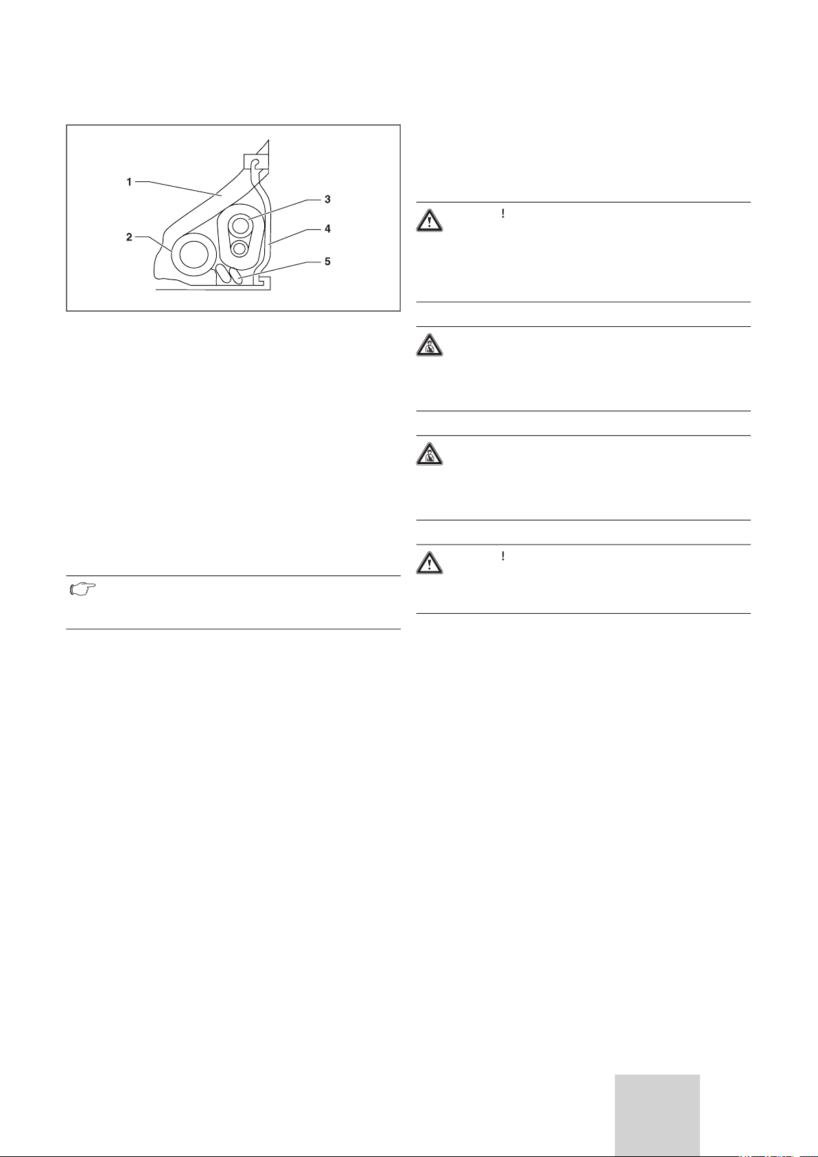
1 Suction valve (gas)
2 Return valve (liquid)
3 Service manifold (suitable for R410a refrigerant)
4 Non-return valve
Warning
testing should only be undertaken by competent
the gas line stop valve of the outdoor unit.
the refrigerant gauges.
the service valve on the outdoor unit as this will release
the pre-charged refrigerant from the outdoor unit.
valves on the service manifold and remove the
test has been successfully completed.
tests are performed and the results correctly logged into
the maintenance record of the machine. The leakage
test must be done with the following frequency:
12.2 Evacuating the Installation
12.2 Evacuating the installation
1 Suction valve (gas)
2 Return valve (liquid)
3 Service manifold (suitable for R410a refrigerant)
4 Non-return joint
the gas line of the outdoor unit.
the service manifold.
vacuum pump
15 minutes (depending on the size of the installation)
to carry out the vacuum.
Preparation for Use 12

Split Type Installation Manual
20
should indicate -0.1 MPa (-76 cmHg - >3 Torr). If the
service manifold gauge is not capable of measuring to
these pressures a separate Torr vacuum gauge should
open and vacuum pump operational.
15 minutes have elapsed: the pressure should not rise.
them (Check all joints and connections to the service
Warning
satisfactory evacuation of the installation has
closed and the vacuum pump switched off: checking
for leaks.
Warning
12.3 Start Up
1 Two-way valve
2 Allen key to open valves
the allen key anticlockwise as far as it will go.
1 Two-way shut off valve
2 Three-way service valve
3 Allen key (not supplied) to open valves
12 Preparation for Use

Split Type Installation Manual
21
EN
1 Valve cap
2 Two and three-way valve covers
12.4 Troubleshooting
Warning
Warning
Preparation for Use 12

Split Type Installation Manual
22
13 Error Codes
OUTDOOR
E1
/
1) Room-temperature sensor may be faulty
2) Indoor PCB may be faulty
E2
/
1) Heat-exchange sensor may be faulty
2) Indoor PCB may be faulty
1) Defrosting temperature sensor may be faulty
2) Outdoor PCB may be faulty
1) Exhaust temperature sensor may be faulty
2) Outdoor PCB may be faulty
so.
1) Ambient temperature sensor may be faulty
2) Outdoor PCB may be faulty
so.
1) Suction temperature sensor may be faulty
2) Outdoor PCB may be faulty
1) The outdoor mainboard may be damp and needs drying
2) The indoor mainboard may be damp and needs drying
3) The linking cable between the indoor and outdoor units
4) The indoor PCB may be faulty
1)
The wiring of compressor is incorrect or the connection is
faulty
2) The SPDU may be faulty
3) Compressor may be damaged.
1) The refrigerant may have been leaked during installation,
2) Exhaust temperature sensor may be faulty
3) The outdoor mainboard is damaged and needs be

Split Type Installation Manual
23
EN
Error Codes 13
OUTDOOR
1) The SPDU may be faulty
2) The power supply is incorrect
3) The system may have been over or under charged with
1) IPM Module may be overheating
2) IPM Module may be damaged
3) Compressor may be damaged
1) Check whether the indoor unit has poor airflow due to
2) The system is over charged with refrigerant.
3) Indoor pipe sensor may be faulty.
1) The indoor PCB might be damaged
2) The outdoor PCB might be damaged
/
1) Check whether Terminal CN2 on the indoor mainboard is
2) The indoor mainboard may be faulty
3) The motor of the indoor unit may be faulty
1) Check whether terminal CN2 on the outdoor mainboard
2) The mainboard of the indoor unit may be faulty
3) The motor of the Outdoor unit may be faulty
1) The connection between IPM and the outdoor PCB may
2)The mainboard of the outdoor unit may be damaged
3)The IPM module may be damaged
1) The IPM module may be damaged
2) Check power supply is correct
3) The transformer of outdoor mainboard is damage
4) The rectifying bridge or IPM module may be faulty
 Loading...