


en Operating and installation
instructions
es Manual de uso e instalación
pt Instruções de uso e instalação
sl Navodila za uporabo in
namestitev
en Country specifics
Publisher/manufacturer
Vaillant GmbH
Berghauser Str. 40 D-42859 Remscheid
Tel. +492191 18 0 Fax +492191 18 2810
info@vaillant.de www.vaillant.de
sensoCOMFORT
VRC 720

en Operating and installation instructions ............ 1
es Manual de uso e instalación ............................ 49
pt Instruções de uso e instalação ....................... 98
sl Navodila za uporabo in namestitev ................. 146
en Country specifics............................................. 193

Contents
Operating and installation instructions
Contents
1 Safety.................................................................... 2
1.1 Intended use.......................................................... 2
1.2 General safety information .................................... 2
1.3 -- Safety/regulations......................................... 2
2 Product description............................................. 3
2.1 Which nomenclature is used? ............................... 3
2.2 What is the effect of the frost protection
function? ................................................................ 3
2.3 What do the following temperatures mean?.......... 3
2.4 What is a zone? ..................................................... 3
2.5 What is the circulation?.......................................... 3
2.6 What is a fixed value control?................................ 3
2.7 What is meant by "time period"?............................ 3
2.8 What is the effect of the hybrid manager?............. 3
2.9 Preventing malfunctions ........................................ 3
2.10 Setting the heat curve............................................ 4
2.11 Display, control elements and symbols ................. 4
2.12 Operating and display functions ............................ 5
3 -- Electrical installation, set-up................... 15
3.1 Selecting the lines................................................ 15
3.2 Connecting a system control to the ventilation
unit....................................................................... 15
3.3 Installing the system control and outdoor
temperature sensor.............................................. 16
6 Fault and maintenance messages ................... 43
6.1 Fault..................................................................... 43
6.2 Fault message..................................................... 43
6.3 Maintenance message ........................................ 43
7 Information about the product ......................... 43
7.1 Observing and storing other applicable
documents ........................................................... 43
7.2 Validity of the instructions.................................... 43
7.3 Data plate ............................................................ 43
7.4 Serial number ...................................................... 44
7.5 CE marking.......................................................... 44
7.6 Guarantee and customer service ........................ 44
7.7 Recycling and disposal ........................................ 44
7.8 Product data in accordance with EU
Ordinance no. 811/2013, 812/2013 ..................... 44
7.9 Technical data – System control.......................... 44
Appendix ............................................................................ 45
A Troubleshooting, maintenance message........ 45
A.1 Troubleshooting................................................... 45
A.2 Maintenance messages....................................... 45
B -- Troubleshooting, maintenance
message ............................................................. 45
B.1 Troubleshooting................................................... 45
B.2 Troubleshooting................................................... 46
B.3 Maintenance messages....................................... 47
Index ................................................................................... 48
4 -- Using the functional modules, basic
system diagram, start-up .................................. 19
4.1 System without functional modules ..................... 19
4.2 System with FM3 functional module.................... 19
4.3 System with FM5 and FM3 functional
modules ............................................................... 20
4.4 Potential application for the functional
modules ............................................................... 20
4.5 Terminal assignment for the FM5 functional
module................................................................. 21
4.6 Terminal assignment for the FM3 functional
module................................................................. 22
4.7 Settings for the basic system diagram codes ...... 23
4.8 Combinations of basic system diagram and
configuration of functional modules ..................... 25
4.9 Basic system diagram and wiring diagram.......... 26
5 -- Start-up...................................................... 43
5.1 Prerequisites for starting up................................. 43
5.2 Running the installation assistants ...................... 43
5.3 Changing the settings later.................................. 43
0020287900_00 sensoCOMFORT Operating and installation instructions 1

1 Safety
1 Safety
1.1 Intended use
In the event of inappropriate or improper use,
damage to the product and other property
may arise.
The product is intended for using an eBUS
interface to control a heating installation with
heat generators from the same manufacturer.
The system control controls based on the
installed system:
– Heating
– Cooling
– Ventilation
– Domestic hot water generation
– Circulation
Intended use includes the following:
– Observance of all other applicable docu-
ments for the product and any other system components
– installing and setting up the product in ac-
cordance with the product and system approval
Intended use also covers installation in accordance with the IP code.
This product can be used by children aged
from 8 years and above and persons with
reduced physical, sensory or mental capabilities or lack of experience and knowledge if
they have been given supervision or instruction concerning use of the product in a safe
way and understand the hazards involved.
Children must not play with the product.
Cleaning and user maintenance work must
not be carried out by children unless they are
supervised.
Any other use that is not specified in these
instructions, or use beyond that specified in
this document, shall be considered improper
use.
1.2 General safety information
1.2.1 Risk caused by inadequate qualifications
The following work must only be carried out
by competent persons who are sufficiently
qualified to do so:
– Set-up
– Dismantling
– Installation
– Start-up
– Decommissioning
▶ Proceed in accordance with current tech-
nology.
Work and functions that must only be carried out or set by the competent person are
marked by the symbol.
1.2.2 Danger caused by improper operation
Improper operation may present a danger to
you and others, and cause material damage.
▶ Carefully read the enclosed instructions
and all other applicable documents, particularly the "Safety" section and the warnings.
▶ As the end user, you should only carry out
those activities for which these instructions provide instructions and that are not
marked with the symbol.
1.3 -- Safety/regulations
1.3.1 Risk of material damage caused by frost
▶ Do not install the product in rooms prone
to frost.
1.3.2 Regulations (directives, laws, standards)
▶ Observe the national regulations, stand-
ards, directives, ordinances and laws.
2 Operating and installation instructions sensoCOMFORT 0020287900_00

Product description 2
24 °C
18:0016:30
22:30
16 °C
21 °C
20:00
A
B
5
1
2
3
4
2 Product description
2.1 Which nomenclature is used?
– System control: Instead of VRC 720
– Remote control: Instead of VR 92
– FM3 or FM3 functional module: Instead of VR 70
– FM5 or FM5 functional module: Instead of VR 71
2.2 What is the effect of the frost protection function?
The frost protection function protects the heating installation
and flat from frost damage.
At outdoor temperatures
– Below 4 °C for longer than four hours, the system control
switches the heat generator on and regulates the target
room temperature to at least 5 °C.
– Above 4 °C, the system control does not switch the heat
generator on, but it monitors the outdoor temperature.
2.3 What do the following temperatures mean?
Desired temp. is the temperature to which you want to heat
up the living rooms.
Set-back temp. is the level below which the temperature
in the living rooms does not fall when outside of the time
periods.
Flow temp. is the temperature at which the heating water
leaves the heat generator.
2.4 What is a zone?
A building can be divided into multiple areas, which are
known as zones. A different requirement can be placed on
the heating installation in each zone.
Examples for dividing into zones:
– Underfloor heating (zone 1) and panel radiator heating
(zone 2) are available in one building.
– A building is made up of several self-contained residen-
tial units. Each residential unit has its own zone.
2.5 What is the circulation?
An additional water pipe is connected to the domestic hot
water pipe and forms a circuit with the domestic hot water
cylinder. A circulation pump facilitates the continuous circulation of domestic hot water through the pipework system
which means that hot water is immediately available, even at
more distant draw-off points.
2.6 What is a fixed value control?
The system control regulates the flow temperature to two
fixed temperatures, which are independent from the room or
outdoor temperature. This control is suitable for a door air
curtain or swimming pool heating, for example.
2.7 What is meant by "time period"?
Example of heating mode in the mode: Time-controlled
A Time
B Temperature
1 Desired temperature
2 Set-back temperature
You can divide a day up into several time periods (3) and (5).
Each time period can comprise an individual start time and
end time. The time periods must not overlap. You can assign
a different desired temperature (1) to each time period.
Example:
16:30 to 18:00; 21 °C
20:00 to 22:30; 24 °C
The system control regulates the living rooms to the desired
temperature within the time periods. In the times outside of
the time periods (4), the system control regulates the living
rooms to the lower set-back temperature (2) that is set.
3 Time period 2
4 Outside of the time
periods
5 Time period 1
2.8 What is the effect of the hybrid manager?
The hybrid manager calculates whether the heat pump or
the additional boiler covers the heat demand cost-effectively.
The decision-making criteria are the set tariffs in relation to
the heat demand.
To ensure that the heat pump and the additional boiler
can work effectively, you must enter the tariffs correctly.
See table SETTINGS menu item (→ Page 8). Otherwise,
increases costs may arise.
2.9 Preventing malfunctions
▶ Do not cover the system control with furniture, curtains or
other objects.
▶ If the system control is installed in the living room, open
all of the thermostatic radiator valves in this room fully.
0020287900_00 sensoCOMFORT Operating and installation instructions 3

2 Product description
A
B
15 10 5 0 -5 -10 -15 -20
20
30
40
50
60
70
80
90
1.2
1.5
1.822.533.54
0.8
1.0
0.4
0.2
0.1
0.6
A
B
CD
18
22
20
0.4
70
60
50
40
30
15 10 5 0 -5 -10 -15 -20
ĮİŰ
ĬĪƀ
ĬįŀĪ
ƀ
īĬƀ
2.10 Setting the heat curve
A Outside temperature °C B Target flow temperature
°C
The figure shows the possible heat curves of 0.1 to 4.0 for a
target room temperature of 20 °C. If, for example, heat curve
0.4 is selected, a flow temperature of 40 °C is maintained at
an outdoor temperature of -15 °C.
2.11 Display, control elements and symbols
2.11.1 Control elements
– Calling up the menu
– Back to the main menu
– Confirming a selection/change
– Saving set values
A Outdoor temperature °C
B Target flow temperature
°C
C Target room temperat-
ure °C
D Axis a
If the heat curve 0.4 is selected and 21 °C is specified for the
target room temperature, the heat curve is then translated,
as shown in the figure. The heat curve is displaced according to the value of the target room temperature along axis a
which is angled at 45°. At an outdoor temperature of -15 °C,
the control system provides a flow temperature of 45 °C.
– One level back
– Cancelling input
– Navigating through the menu structure
– Reducing or increasing the set value
– Navigating to individual numbers/letters
– Calling up help
– Calling up the time programme assistant
Active control elements light up green.
Press once: You access the basic display.
Press twice: You access the menu.
2.11.2 Symbols
Time-controlled heating active
Button lock active
Maintenance required
4 Operating and installation instructions sensoCOMFORT 0020287900_00
Fault in the heating installation
Contact the competent person
Noise reduction mode active
Most energy-efficient heating mode active

Product description 2
2.12 Operating and display functions
Note
The functions described in this section are not available for all system configurations.
To call up the menu, press twice.
2.12.1 CONTROL menu item
MENU → CONTROL
→ Zone
→ Name of zone Changing the name Zone 1, which was set at the factory
→ Heating → Mode: → Manual → Desired temperature: °C
Uninterrupted retention of the desired temperature
→ Time-contr. → Weekly planner
→ Set-back temperature: °C
Weekly planner: Up to 12 time periods and desired temperatures can be set per day
The competent person sets how the heating installation behaves outside of the time period in the
Set-back mode: function.
In Set-back mode: means:
– Eco: The heating is switched off outside of the time periods. Frost protection is activated.
– Normal: The set-back temperature applies outside of the time periods.
Desired temperature: °C: Applies within the time periods
→ Off
Heating is switched off, domestic hot water continues to be available, frost protection is activated
→ Cooling → Mode: → Manual → Desired temperature: °C
Uninterrupted retention of the desired temperature
→ Time-contr. → Weekly planner
→ Desired temperature: °C
Weekly planner: Up to 12 time periods can be set per day; cooling is switched off outside of the
time periods
Desired temperature: °C: Applies within the time periods
Cooling is switched off outside of the time periods
→ Off
Cooling is switched off, domestic hot water remains available
→ Absence → All: Applies only to any zones within the specified time period
→ Zone: Applies for the selected zone in the specified time period
Heating and domestic hot water mode is switched off, existing ventilation operates at the lowest
ventilation level, frost protection is activated
→ Cooling for several days Cooling mode is activated in the specified time period, cooling mode and desired temperature are
→ Fixed value control, circuit 1
→ Heating → Mode: → Manual
→ Domestic hot water
used from the Cooling function
Uninterrupted retention of the Target flow temp., desired: °C that the competent person set.
→ Time-contr. → Weekly planner
Weekly planner: Up to 12 time periods can be set per day
Within the time period, the Target flow temp., desired: °C is used.
Outside of the time periods, the Target flow temp., set-back: °C is used or the heating circuit is
switched off.
At a Target flow temp., set-back: °C = 0 °C, the frost protection can no longer be guaranteed.
The competent person sets both of these temperatures.
→ Off
The heating circuit is switched off.
0020287900_00 sensoCOMFORT Operating and installation instructions 5

2 Product description
MENU → CONTROL
→ Mode: → Manual → DHW temperature
Uninterrupted retention of the domestic hot water temperature
→ Time-contr. → Domestic hot water weekly planner
→ DHW temperature: °C
→ Circulation weekly planner
Domestic hot water weekly planner: Up to three time periods can be set per day
DHW temperature: °C: Applies within the time periods
Domestic hot water mode is switched off outside of the time periods
Circulation weekly planner: Up to three time periods can be set per day
The circulation pump pumps hot water to the draw-off points within the time periods
Outside of the time periods, the circulation pump is switched off
→ Off
Domestic hot water mode is switched off
→ DHW circuit 1
→ Mode: → Manual → DHW temperature: °C
Uninterrupted retention of the domestic hot water temperature
→ Time-contr. → Domestic hot water weekly planner
→ DHW temperature: °C
Domestic hot water weekly planner: Up to three time periods can be set per day
DHW temperature: °C: Applies within the time periods
Domestic hot water mode is switched off outside of the time periods
→ Off
Domestic hot water mode is switched off
→ DHW boost Heating up the water in the cylinder once
→ Ventilation
→ Mode: → Normal → Normal ventilation level:
Uninterrupted ventilation at ventilation level: Normal
→ Time-contr. → Weekly planner
→ Normal ventilation level:
→ Reduced ventilation level:
Weekly planner: Up to 12 time periods can be set per day
Normal ventilation level:: Applies within the time periods
Reduced ventilation level:: Applies outside of the time periods
→ Reduced
Uninterrupted ventilation at ventilation level: Reduced
→ Air quality sensor 1:
ppm
→ Heat recovery: → On
→ Air quality limit: ppm The ventilation unit keeps the CO2content in the room air below the set value.
→ Ventilation boost Heating mode is switched off for 30 minutes and, if available, the ventilation unit runs at the highest
→ Humidity prevention → Max. room air humidity: %rel: If the value is exceeded, the dehumidifier switches on. If the value
→ Time programme assistant Programming of the desired temperature for Monday–Friday and Saturday–Sunday; the program-
Measures the CO2content of the room air
Uninterrupted recovery of the heat from the extract air
→ Auto
Internal check of whether the outdoor air is guided via the heat recovery or directly into the living
room. See the operating instructions for the ventilation unit.
→ Off
Heat recovery is switched off
ventilation level.
is not reached, the dehumidifier switches off.
ming applies for the time-controlled Heating Cooling, Domestic hot water, Circulation and Ventil-
ation functions
Overwrites the weekly planner for the Heating, Cooling, Domestic hot water, Circulation and
Ventilation functions
6 Operating and installation instructions sensoCOMFORT 0020287900_00
Product description 2
MENU → CONTROL
→ Green iQ: Switching on the most energy-efficient heating mode, if your installation supports this.
→ Sytem off Installation is switched off. Frost protection and, if available, ventilation remain activated at the lowest
2.12.2 INFORMATION menu item
MENU → INFORMATION
→ Current temperatures
→ Zone
→ DHW temperature
→ DHW circuit 1
→ Water pressure: bar
→ Current room air humidity
→ Energy data
→ Solar yield
→ Environmental yield
→ Power consumption → Heating
→ Fuel consumption → Heating
→ Heat recovery
Display of energy consumption and energy yield
In the display and in the app that can also be used, the control displays values for the energy consumption and/or the energy yield.
The control displays an estimation of the values for the installation. Among other things, the values are influenced by the following:
– The installation/design of the heating installation
– User behaviour
– Seasonal environmental conditions
– Tolerances and components
External components, such as external heating pumps or valves, and other consumers and appliances in the household are still not
taken into consideration.
The deviations between the energy consumption or energy yield that is displayed and the actual energy consumption or energy yield
may be significant.
The specifications for the energy consumption or energy yield are not suitable to be used to create or compare energy billing.
The following can be read: Current month, Last month, Current year, Last year, Total
→ Burner status:
→ Control elements Explanation of the control elements
→ Menu introduction Explanation of the menu structure
→ Competent person contact info
→ Serial number
level.
→ Domestic hot water
→ Cooling
→ Installation
→ Domestic hot water
→ Installation
0020287900_00 sensoCOMFORT Operating and installation instructions 7

2 Product description
2.12.3 SETTINGS menu item
MENU → SETTINGS
→ Installer level
→ Enter access code Access to the installer level, factory setting: 00
→ Competent person con-
tact info
→ Service date: Enter the next service date for a connected component, e.g. heat generator, heat pump, ventilation
→ Fault history Faults are listed in chronological order
→ Installation configuration Functions (→ Installation configuration menu item)
→ Sensor/actuator test Selecting a connected functional module and
→ Noise reduction mode Set the time programme in order to reduce the noise level.
→ Screed drying Activate the Screed drying profile function for freshly laid screed in accordance with the construc-
→ Change code
→ Language, time, display
→ Language:
→ Date: After the power is switched off, the date is retained for approx. 30 minutes.
→ Time: After the power is switched off, the time is retained for approx. 30 minutes.
→ Display brightness:
→ Daylight saving time: → Automatic
For outdoor temperature sensors with DCF77 receivers, the Daylight saving time: function is not used. The conversion to summer/winter time takes place via the DCF77 signal. The change takes place:
– On the last weekend in March at 02:00 (daylight saving time)
– On the last weekend in October at 03:00 (standard time)
→ Tariffs
→ Tariff for back-up boiler: Enter a gas, oil or electricity tariff
→ Electricity tariff type:
(for heat pump)
The hybrid manager uses the tariffs and the heat demand to calculate the costs for the back-up boiler and the heat pump. The more
cost-effective component is used for the heat generation.
→ Offset
→ Room temperature: K Comparison of the temperature difference between the measured value in the system control and
→ Outdoor temperature: K Comparison of the temperature difference between the measured value in the outdoor temperature
→ Factory settings The system control resets all of the settings to the factory settings and calls up the installation assist-
Entering contact details
unit
– carrying out a function check of the actuators.
– Carry out a plausibility check of the sensors.
tion regulations.
The system control regulates the flow temperature independently of the outdoor temperature. Setting
screed drying (→ Installation configuration menu item)
→ Manual
→ Single tariff → High tariff:
The costs are always calculated using the high tariff.
→ Dual tariff → Dual tariff weekly planner
→ Low tariff:
Dual tariff weekly planner: Up to 12 time periods can be set per day
High tariff:: Applies within the time periods
Low tariff:: Applies outside of the time periods
The costs are calculated using the high and low tariffs.
the value for a reference thermometer in the living room.
sensor and the value for a reference thermometer in the living room.
ant.
Only the competent person can call up the installation assistant.
8 Operating and installation instructions sensoCOMFORT 0020287900_00

Product description 2
2.12.4 Installation configuration menu item
MENU → SETTINGS → Installer level → Installation configuration
→ Installation
→ Water pressure: bar
→ eBUS components List of eBUS components and their software versions
→ Adaptive heat curve: Automatic fine adjustment of the heat curve. Prerequisite:
– The suitable heat curve for the building is set in the Heat curve: function.
– The correct zone is assigned to the system control or the remote control in the Zone
assignment: function.
– Expanded is selected in the Room temp. mod.: function.
→ Automatic cooling: When a heat pump is connected, the system control automatically switches between heating
→ Outdoor temp., 24 hr av.: °C
→ Cooling at outdoor temp.: °C Cooling starts once the outdoor temperature (24-hour average) exceeds the set temperature.
→ Source regeneration: The system control switches the Cooling function on and guides the heat from the living
→ Current room air hum.: %rel
→ Current dew point: °C
→ Hybrid manager: → triVAl The heat generator is selected based on the set tariffs in relation to the
→ Heating bivalence point: °C If the outdoor temperature falls below the set value, the system control enables the back-up
→ DHW bivalence point: °C If the outdoor temperature falls below the set value, the system control activates the back-up
→ Alternative point: If the outdoor temperature falls below the set value, the system control switches the heat
→ LHM temperature: °C Set a low target flow temperature. If the heat pump fails, the back-up boiler fulfils the heat
→ Back-up boiler type: Select a type for the heat generator that is also installed. An incorrect selection may lead to
→ ESCO: Define what you want to deactivate when the signal is sent by the energy supply company.
→ Back-up boiler: → Off The back-up boiler does not support the heat pump.
→ Installation flow temperature: °C Measured temperature, e.g. downstream of the low loss header
mode and cooling mode.
room back to the earth via the heat pump. Prerequisite:
– The Automatic cooling: function has been activated.
– The Absence function is active.
heat demand.
→ Bivalence pt The heat generator is selected based on the outdoor temperature (
Heating bivalence point: °C and Alternative point).
boiler to operate in parallel with the heat pump in heating mode.
Prerequisite: Bivalence pt is selected in the Hybrid manager: function.
boiler in parallel with the heat pump.
pump off and the back-up boiler meets the heat demand in heating mode.
Prerequisite: Bivalence point is selected in the Hybrid manager: function.
demand, which leads to higher heating costs. The end user should recognise that heat loss
means that there is a problem with the heat pump.
The end user can use the Mode: Temporary back-up boiler mode function to enable the
back-up boiler and therefore deactivate the target flow temperature that is set here.
increased costs.
Prerequisite: triVAl is selected in the Hybrid manager: function.
The selection remains deactivated until the energy supply company cancels the signal.
The heat generator ignores the deactivation signal as soon as the frost protection function is
active.
The back-up boiler is activated for the anti-legionella function, frost protection or de-icing.
→ Heating The back-up boiler supports the heat pump during heating.
The back-up boiler is activated for the anti-legionella function.
→ DHW The back-up boiler supports the heat pump during domestic hot water
generation.
The back-up boiler is activated for frost protection or de-icing.
→ DHW + heat. The back-up boiler supports the heat pump during domestic hot water
generation and heating.
0020287900_00 sensoCOMFORT Operating and installation instructions 9

2 Product description
MENU → SETTINGS → Installer level → Installation configuration
→ Buffer cylinder offset: K In the case of excessive current, the buffer cylinder is heated up to the flow temperature +
→ Actuation reversal: → Off The system control always actuates the heat generators in the sequence
→ Actuation sequence: Sequence in which the system control actuates the heat generators.
→ Conf. ext. input: Select whether the external heating circuit is deactivated using a bridge or open terminals.
→ Basic system diagram config.
→ Basic system diagram code: Systems are roughly grouped according to their connected system components. Each group
→ FM5 configuration: Each configuration corresponds to a defined terminal assignment (→ Connection assignment
→ FM3 configuration: Each configuration corresponds to a defined terminal assignment (→ Connection assignment
→ FM3 MO: Select the multi-function output's function assignment.
→ FM5 MO: Select the multi-function output's function assignment.
→ HP control module configuration
→ MO 2: Select the multi-function output's function assignment.
→ MI: → Not connec-
The system control queries whether a signal is present at the heat pump's input. For example:
–
aroTHERM input: MI for the heat pump control module
– flexoTHERM input: X41, terminal in the functional drawing
→ Heat generator 1
→ Heat pump 1
→ HP control module
→ Status:
→ Current flow temperature: °C
→ Circuit 1
→ Circuit type: → Inactive The heating circuit is not being used.
set offset via the heat pump. Prerequisite:
– A photovoltaic installation is connected.
– Photovoltaics is activated in the HP control module configuration → MI: function.
1, 2, 3, etc.
→ On Once a day, the system control sorts the heat generators based on their
Prerequisite: The heating installation contains a cascade.
Prerequisite: The heating installation contains a cascade.
Prerequisite: The FM5 and/or FM3 functional module is connected.
has a basic system diagram code. Based on the code that is entered, the system control
enables the system-related functions.
You can use the connected components to determine the basic system diagram code for the
installed installation (→ Using the functional modules, basic system diagram, start-up) and
enter this here.
for the FM5 functional module). The terminal assignment determines which functions contain
the inputs and outputs.
Select the configuration that suits the installation that is installed.
for the FM3 functional module). The terminal assignment determines which functions contain
the inputs and outputs.
Select the configuration that suits the installation that is installed.
ted
→ 1 x circula-
tion
→ Photovoltaics In the case of excessive current, a signal is present and the system con-
→ Heating The heating circuit is being used to heat and is weather-compensated.
→ Fixed value The heating circuit is used for heating and is maintained at a fixed target
→ DHW The heating circuit is being used as a domestic hot water circuit for an
actuation time.
The back-up heater is excluded from this sorting.
The system control ignores the signal present.
The end user has pressed the circulation button. The system control
activates the circulation pump for a short time period.
trol activates the DHW boost function once. If the signal persists, the
buffer cylinder is charged to the flow temperature + buffer cylinder offset
until the signal at the heat pump drops off again.
Depending on the basic system diagram, the heating circuit may be a
mixing circuit or a direct circuit.
flow temperature.
additional cylinder.
10 Operating and installation instructions sensoCOMFORT 0020287900_00

Product description 2
MENU → SETTINGS → Installer level → Installation configuration
→ Circuit type: → Increase in
→ Status:
→ Target flow temperature: °C
→ Actual flow temperature: °C
→ Target return temperature: °C Select a temperature at which the heating water should flow back into the floor-standing
→ OT switch-off threshold: °C Enter the upper limit for the outdoor temperature. If the outdoor temperature rises above the
→ Target flow temp., desired: °C Select the temperature for the fixed value circuit which applies within the time period.
→ Target flow temp., set-back: °C Select the temperature for the fixed value circuit which applies outside of the time period.
→ Heat curve: The heat curve (→ section "Product description") is the dependence of the flow temperature
→ Min. target flow temperature:°C Enter the lower limit for the target flow temperature. The system control compares the set
→ Max. target flow temperature:°C Enter the upper limit for the target flow temperature. The system control compares the set
→ Set-back mode:
The behaviour can be adjusted separately for each heating circuit.
→ Room temp. mod.:
The installed temperature sensor measures the current room temperature. The system control calculates a new target room temper-
ature that is used to adjust the flow temperature.
– Difference = Set target room temperature - current room temperature
–
New target room temperature = Set target room temperature + difference
Prerequisite: In the Zone assignment: function, the system control and/or the remote control is assigned to the zone in which the
system control or remote control is installed.
The Room temp. mod.: function is ineffective if No assignmt is activated in the Zone assignment: function.
→ Cooling possible: Prerequisite: A heat pump is connected.
→ Dew point monitoring: The system control compares the set minimum cooling target flow temperature with the cur-
return
boiler.
set value, the system control deactivates heating mode.
on the outdoor temperature for the desired temperature (target room temperature).
value with the calculated target flow temperature, and regulates to the larger of these values.
value with the calculated target flow temperature, and regulates to the smaller of these values.
→ Eco The heating function is switched off and the frost protection function is
→ Normal The heating function is switched on. The system control regulates to the
→ Inactive
→ Active Adjusting the flow temperature based on the current room temperature.
→ Expanded Adjusting the flow temperature based on the current room temperature.
rent dew point + set dew point offset. The system control selects the higher temperature for
the target flow temperature in order to prevent condensate.
Prerequisite: The Cooling possible: function has been activated.
The heating circuit is used to increase the return flow. The increase in
return prevents an excessive temperature difference between the heating flow and return, and protects against corrosion in the floor-standing
boiler when the dew point is not reached for an extended period.
activated.
At outdoor temperatures that are below 4 °C for longer than four hours,
the system control switches the heat generator on and regulates to the
Set-back temperature: °C. At an outdoor temperature above 4 °C, the
system control switches the heat generator off. The monitoring of the
outdoor temperature remains active.
Heating circuit behaviour outside of the time periods. Prerequisite:
– Time-contr. is activated in the Heating → Mode: function.
– Active or Inactive is activated in the Room temp. mod.: function.
If Expanded is activated in the Room temp. mod.:, the system control
regulates to the target room temperature 5 °C independently of the outdoor temperature.
Set-back temperature: °C.
Prerequisite: Time-contr. is activated in the Heating → Mode: function.
The system control also activates/deactivates the zone.
– The zone is deactivated: Current room temperature + 2/16 K > set
room temperature
– Zone is activated: Current room temperature < set room temperature
- 3/16 K
0020287900_00 sensoCOMFORT Operating and installation instructions 11

2 Product description
MENU → SETTINGS → Installer level → Installation configuration
→ Min. cooling targ. flow temp.: °C The system control regulates the heating circuit to the Min. cooling targ. flow temp.: °C.
Prerequisite: The Cooling possible: function has been activated.
→ Dew point offset: K Safety margin that is added to the current dew point. Prerequisite:
– The Cooling possible: function has been activated.
– The Dew point monitoring: function has been activated.
→ Ext. heat demand: Display showing whether a heat demand is present at an external input.
When installing an FM5 or FM3 functional module, external inputs are available, depending
on the configuration. You can connect an external zone controller, for example, to this external input.
→ DHW temperature: °C Desired temperature at the withdrawal point. The heating circuit is used as a domestic hot
→ Actual cylinder temperature: °C The heating circuit is used as a domestic hot water circuit.
→ Pump status:
→ Mixing valve status: %
→ Zone
→ Zone activated: Deactivate zones that are not required. All existing zones appear in the display. Prerequisite:
→ Zone assignment: Assign the system control and/or remote control to the selected zone. The system control
→ Zone valve status:
→ Domestic hot water
→ Cylinder: If there is an existing domestic hot water cylinder, the Active setting must be selected.
→ Target flow temperature: °C
→ Cylinder charging pump:
→ Circulation pump:
→ Anti-legio. day: Define the days on which you want the anti-legionella function to run. On these days, the
→ Anti-legio. time: Define the time at which you want the anti-legionella function to run.
→ Cylinder charging hysteresis: K The cylinder charging starts as soon as cylinder temperature < desired temperature - hyster-
→ Cylinder charging offset: K Desired temperature + offset = flow temperature for the domestic hot water cylinder.
→ Max. cyl. charging time: Setting the maximum time at which the domestic hot water cylinder can be charged without
→ Cyl. charg. anti-cycl. time: min Setting the time period during which the cylinder charging is blocked after the maximum cyl-
→ Parallel cylinder charging: When charging the domestic hot water cylinder, the mixing circuit is heated in parallel. The
→ Buffer cylinder
→ Cylinder temp., top: °C Actual temperature in the upper section of the buffer cylinder
→ Cylinder temp., bottom: °C Actual temperature in the lower section of the buffer cylinder
→ DHW temp. sensor, top: °C Actual temperature in the upper part of the domestic hot water section of the buffer cylinder
→ DHW temp. sensor, bottom: °C Actual temperature in the lower part of the domestic hot water section of the buffer cylinder
→ Heat. temp. sensor, top: °C Actual temperature in the upper part of the heating section of the buffer cylinder
→ Heat. temp. sensor, bottom: °C Actual temperature in the lower part of the heating section of the buffer cylinder
→ Solar cylinder, bottom: °C Actual temperature in the lower section of the solar cylinder
water circuit.
The existing heating circuits are activated in the Circuit type: function.
and/or remote control must be installed in the selected zone. The control system also uses
the room temperature sensor for the assigned unit. The remote control uses all of the values for the assigned zone. The Room temp. mod.: function is ineffective if you have not assigned any zones.
water temperature is increased to above 60 °C. The circulation pump is activated. The function ends after 120 minutes at the latest.
If the Absence function is activated, the anti-legionella function is not carried out. As soon
as the Absence function ends, the anti-legionella function is carried out.
Heating installations with heat pumps use the back-up boiler for legionella protection.
esis value.
interruption. If the maximum time or the target temperature is reached, the system control
enables the heating function. The setting Off means that the cylinder charging time is not
restricted.
inder charging time has elapsed. During the blocked time, the system control enables the
heating function.
non-mixed heating circuit is always switched off during cylinder charging.
12 Operating and installation instructions sensoCOMFORT 0020287900_00

Product description 2
MENU → SETTINGS → Installer level → Installation configuration
→ Max. DHW targ. flow temp..: °C Setting the maximum buffer cylinder target flow temperature for the domestic hot water sta-
→ Max. temp. of cylinder 1: °C Setting the maximum cylinder temperature. The solar circuit stops the cylinder charging as
→ Solar circuit
→ Collector temperature: °C
→ Solar pump:
→ Solar yield sensor: °C
→ Solar flow rate quantity: Entering the volume flow to calculate the solar yield. If a solar pump station is installed, the
→ Solar pump kick: Accelerated recording of the collector temperature. When the function is activated, the solar
→ Solar circuit prot. function: °C Setting the maximum temperature that must not be exceeded in the solar circuit. If the max-
→ Min. collector temperature: °C Setting the minimum collector temperature that is required for the solar charging switch-on
→ Purging time: min Setting the time period during which the solar circuit is purged. The system control stops the
→ Current flow rate: l/min Current volume flow of the solar pump station
→ Solar cylinder 1
→ Switch-on differential: K Setting the differential value for starting the solar charging.
→ Switch-off differential: K Setting the differential value for stopping the solar charging.
→ Maximum temperature: °C Set the maximum cylinder charging temperature for the cylinder protection.
→ Solar cylinder, bottom: °C
→ 2nd diff. temp control
→ Switch-on differential: K Setting the differential value for starting the temperature difference control, such as solar
→ Switch-off differential: K Setting the differential value for stopping the temperature difference control, such as solar
→ Minimum temperature: °C Setting the minimum temperature for starting the differential temperature control.
tion. The set maximum target flow temperature must be lower than the maximum flow temperature for the heat generator.
If the maximum target flow temperature is set too low, the domestic hot water station cannot
reach the target cylinder temperature. While the target cylinder temperature is not reached,
the system control does not enable the heat generator for heating mode.
You can find the maximum flow temperature in the installation instructions for the heat generator.
soon as the maximum cylinder temperature has been reached.
system control ignores that value that has been entered and uses the volume flow that is
supplied from the solar pump station.
The value 0 means the automatic recording of the volume flow.
pump is switched on for a short time and the heated solar fluid is transported to the measuring point more quickly.
imum temperature at the collector sensor is exceeded, the solar pump switches off to protect
the solar circuit against overheating.
differential. The differential temperature control can only start once the minimum collector
temperature has been reached.
function once the specified purging time has elapsed, the solar circuit protection function is
active or the max. cylinder temperature has been exceeded.
If the temperature difference between the cylinder temperature sensor at the bottom and the
collector temperature sensor is greater than the set differential value and the set minimum
collector temperature, the cylinder charging is started.
The differential value can be defined separately for two connected solar cylinders.
If the temperature difference between the bottom cylinder temperature sensor and the collector temperature sensor is smaller than the set differential value and the set minimum collector temperature, the cylinder charging is stopped. The switch-off differential temperature
value must be at least 1 K less than the set switch-on differential temperature value.
If the temperature at the bottom cylinder temperature sensor is higher than the set maximum
cylinder charging temperature, the solar charging is interrupted.
The solar charging is only enabled again once the temperature at the bottom cylinder temperature sensor has fallen by between 1.5 K and 9 K, depending on the maximum temperature. The set maximum temperature must not exceed the maximum permissible cylinder temperature of the cylinder.
heating support.
If the temperature difference between differential temperature sensor 1 and differential tem-
perature sensor 2 is greater than the set switch-on differential and the set minimum temperature at differential temperature sensor 1, the differential temperature control is started.
heating support.
If the temperature difference between differential temperature sensor 1 and differential tem-
perature sensor 2 is lower than the set switch-off differential and the set maximum temperature at differential temperature sensor 2, the differential temperature control is stopped.
0020287900_00 sensoCOMFORT Operating and installation instructions 13

2 Product description
MENU → SETTINGS → Installer level → Installation configuration
→ Maximum temperature: °C Setting the maximum temperature for stopping the differential temperature control.
→ Diff. temp. sensor 1:
→ Diff. temp. sensor 2:
→ Diff. temp. sensor output:
→ Screed drying profile Setting target flow temperature per day in accordance with the construction regulations
14 Operating and installation instructions sensoCOMFORT 0020287900_00

3 -- Electrical installation, set-up
Only qualified electricians may carry out the electrical installation.
The heating installation must be decommissioned before
work is carried out on it.
3.1 Selecting the lines
▶ Do not use flexible lines for power supply cables.
▶ Use sheathed cables for power supply cables (e.g. NYM
3 x 1.5).
Line cross-section
eBUS line (extra-low
voltage)
Sensor line (extra low
voltage)
Line length
Sensor lines
Bus lines
≥ 0.75 mm²
≥ 0.75 mm²
≤ 50 m
≤ 125 m
-- Electrical installation, set-up
3
3.2 Connecting a system control to the ventilation unit
1. Connect the system control to the ventilation unit as de-
scribed in the installation instructions for the ventilation
unit.
Condition: Ventilation unit connected to the eBUS without VR 32, Ventilation unit without eBUS heat generator
▶ Connect the eBUS line to the eBUS terminals in the sys-
tem control's wall base.
▶ Connect the eBUS line to the eBUS terminals on the
ventilation unit.
Condition: Ventilation unit connected to the eBUS with VR 32, Ventilation
unit with up to two eBUS heat generators
▶ Connect the eBUS line to the eBUS terminals in the sys-
tem control's wall base.
▶ Connect the eBUS line to the eBUS of the heat gener-
ator.
▶ Set the address switch for the VR 32 in the ventilation
unit to position 3.
Condition: Ventilation unit connected to the eBUS with VR 32, Ventilation
unit with more than two eBUS heat generators
▶ Connect the eBUS line to the eBUS terminals in the sys-
tem control's wall base.
▶ Connect the eBUS line to the common eBUS on the
heat generator.
▶ Determine the highest possible position on the address
switches of the VR 32 for the connected heat generator.
▶ Set the address switch of the VR 32 in the ventilation
unit to the second highest position.
0020287900_00 sensoCOMFORT Operating and installation instructions 15

3
Ø6
VRC 720 VRC 693 VRC 9535
H05VVF
2 x 0,75 mm²
VRC 720
1,5 m
Ø6
60
1.
≤25 mm
A
B
C
2.
-- Electrical installation, set-up
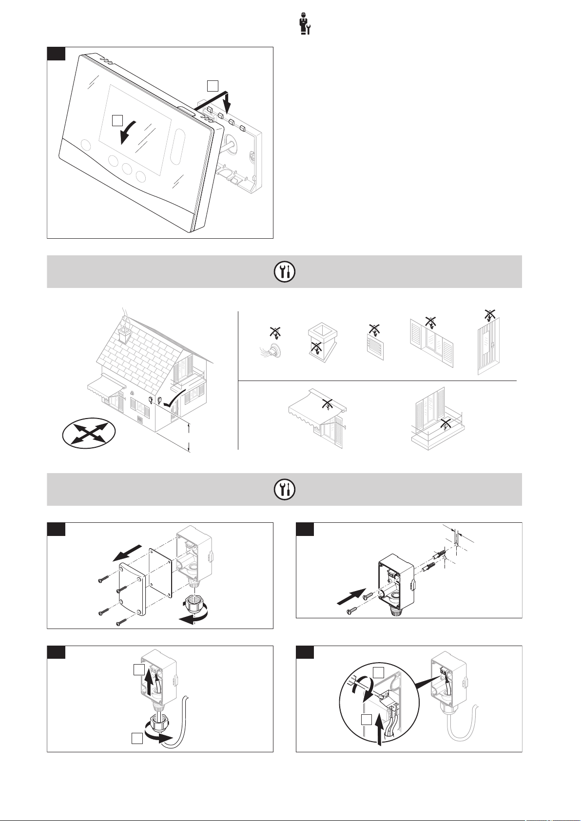
3.3 Installing the system control and outdoor temperature sensor
16 Operating and installation instructions sensoCOMFORT 0020287900_00
-- Electrical installation, set-up
A
B
3.
VRC 693, VRC 9535
E
W
S
N
≥ 2,5 m
VRC 693
1.
Ø6
2.
3.
B
A
4.
B
A
3
0020287900_00 sensoCOMFORT Operating and installation instructions 17

3
5.
6.
VRC 9535
D
C
F
O
T
AF
1.
Ø6
D
C
F
O
T
AF
2.
D
C
F
O
T
AF
3.
B
A
D
C
F
O
T
AF
4.
D
C
F
O
T
AF
B
A
D
C
F
O
T
AF
5.
6.
-- Electrical installation, set-up
18 Operating and installation instructions sensoCOMFORT 0020287900_00

-- Using the functional modules, basic system diagram, start-up
eBUS
VRC 720
VRC 720
eBUS
FM3 (VR 70)
4 -- Using the functional modules, basic system diagram, start-up
4.1 System without functional modules
4
Simple systems with a direct heating circuit do not require a functional module.
4.2 System with FM3 functional module
Systems with two heating circuits that must be controlled separately from each other require the FM3 functional module.
The VR 92 remote control cannot be added to the system.
0020287900_00 sensoCOMFORT Operating and installation instructions 19
4
VRC 720
eBUS
VR 92
FM5 (VR 71)
FM3 (VR 70)
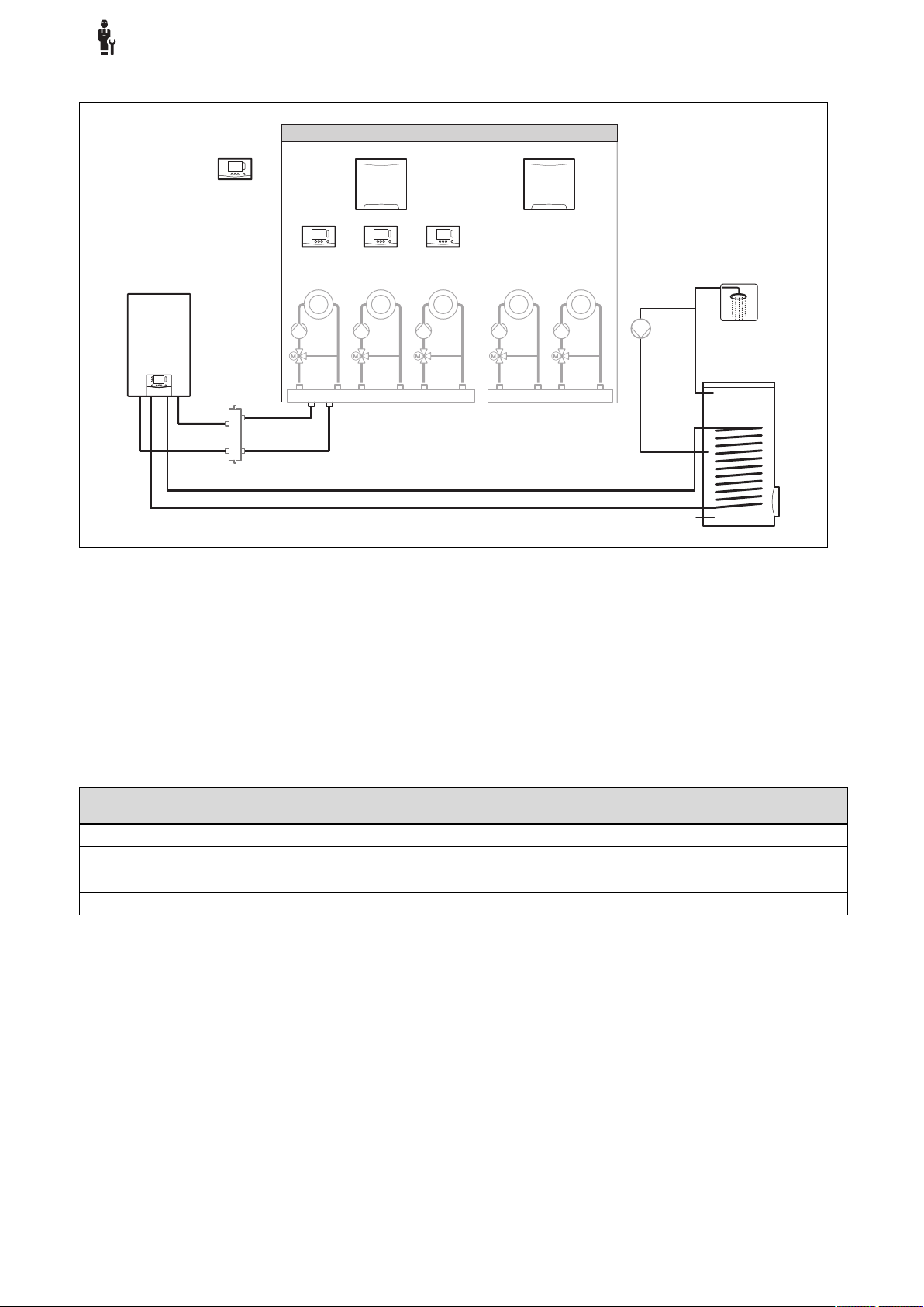
-- Using the functional modules, basic system diagram, start-up
4.3 System with FM5 and FM3 functional modules
Systems with more than two mixed heating circuits require the FM5 functional module.
The system may comprise the following:
– Maximum 1 x FM5 functional module
– Maximum 3 x FM3 functional modules, in addition to the FM5 functional module
– Maximum 4 x VR 92 remote controls, which can be installed in each heating circuit
– Maximum 9 x heating circuits, which you achieve using 1 x FM5 functional module and 3 x FM3 functional modules
4.4 Potential application for the functional modules
4.4.1 FM5 functional module
Each configuration corresponds to a defined connection assignment of the FM5 (→ Page 21) functional module.
Configuration
1 Solar heating and/or domestic hot water support with two solar cylinders Max. 2
2 Solar heating and/or domestic hot water support with one solar cylinder Max. 3
3 3 x mixed heating circuits Max. 3
6 allSTOR multi-functional buffer cylinder and domestic hot water station Max. 3
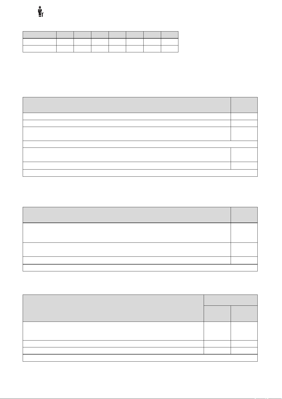
4.4.2 FM3 functional module
If a FM3 functional module is installed, the system has one mixed and one non-mixed heating circuit.
The potential configuration (FM3) corresponds to a defined terminal assignment for the FM3 (→ Page 22) functional module.
System property Mixed heat-
ing circuits
20 Operating and installation instructions sensoCOMFORT 0020287900_00

-- Using the functional modules, basic system diagram, start-up
S112S212S312S412S512S612S712S812S912S1012S1112S12
OI
S13
OI
R7/8
N12
R13
NN
R11/12
N12
R9/10
N12
R6
L
N
R5
L
N
R4
L
N
R3
L
N
R2
L
N
R1
L
N
230V
L
N
230V
L
N
BUS
-+
4
5
1
2
3
R7/8
N12
R11/12
N12
R9/10
N12
S12
OI
S13
OI
4.4.3 FM3 and FM5 functional modules
If the FM3 and FM5 functional modules are installed in a system, each additional installed FM3 functional module adds two
mixed heating circuits to the system.
The potential configuration (FM3+FM5) corresponds to a defined terminal assignment for the FM3 (→ Page 22) functional
module.
4.5 Terminal assignment for the FM5 functional module
4
1 Input sensor terminals
2 Signal terminals
4 Output relay terminals
5 Power supply
3 eBUS terminal
When connecting, pay attention to the polarity!
S6 to S11 sensor terminals: An external control can also be connected
S12, S13 signal terminals: I = input, O = output
R7/8, R9/10, R11/12 mixer output: 1 = open, 2 = closed
You can configure the contacts for external inputs in the system control.
– Open, deactiv.: Contacts open, no heat demand
– Bridge, deactiv.: Contacts closed, no heat demand
Configuration
1 3f1 3f2 9gSolar MA 3j 3c/9e 9k1op/
2 3f1 3f2 3f3 MA 3j 3c/9e 9k1op/
3 3f1 3f2 3f3 MA – 3c/9e 9k1op/
6 3f1 3f2 3f3 MA 9gSolar 3c/9e 9k1op/
Configuration
1 SysFlow FS1 FS2 DHW
2 SysFlow FS1 FS2 FS3 DHW DHWBt COL Solar
R1 R2 R3 R4 R5 R6 R7/R8 R9/R10 R11/R12 R13
S1 S2 S3 S4 S5 S6 S7 S8 S9 S10 S11 S12 S13
DHW DHWBt COL Solar
Bt2
yield
yield
9k1cl
9k1cl
9k1cl
9k1cl
9k2op/
9k2cl
9k2op/
9k2cl
9k2op/
9k2cl
9k2op/
9k2cl
– –
9k3op/
9k3cl
9k3op/
9k3cl
9k3op/
9k3cl
DEM2 TD1 TD2 PWM –
– TD1 TD2 PWM –
–
–
–
0020287900_00 sensoCOMFORT Operating and installation instructions 21

4
S112S212S312S412S512S612S7
OI
R3/4
N12
R5/6
N12
R2
L
N
R1
L
N
230V
L
N
BUS
-+
5
67
1
2
4
3
R3/4
N12
R5/6
N12
-- Using the functional modules, basic system diagram, start-up
Configur-
S1 S2 S3 S4 S5 S6 S7 S8 S9 S10 S11 S12 S13
ation
3 SysFlow FS1 FS2 FS3 BufBt DEM1 DEM2 DEM3 DHW – – – –
6 SysFlow FS1 FS2 FS3 BufBt BufBtCH BufTop
DHW
BufBt
DHW
DEM1 DEM2 DEM3 – –
Meaning of the abbreviations (→ Page 26)
4.5.1 Sensor assignment
Configuration
1 VR 10 VR 10 VR 10 VR 10 VR 10 VR 10 VR 11 VR 10 – VR 10 VR 10 – –
2 VR 10 VR 10 VR 10 VR 10 VR 10 VR 10 VR 11 VR 10 – VR 10 VR 10 – –
3 VR 10 VR 10 VR 10 VR 10 VR 10 – – – VR 10 VR 10 – – –
6 VR 10 VR 10 VR 10 VR 10 VR 10 VR 10 VR 10 VR 10 – – – VR 10 –
S1 S2 S3 S4 S5 S6 S7 S8 S9 S10 S11 S12 S13
4.6 Terminal assignment for the FM3 functional module
1 Input sensor terminals
2 Signal terminal
3 Address switch
5 Mixer output
6 Output relay terminals
7 Power supply
4 eBUS terminal
S2, S3 sensor terminals: An external control can also be connected
R3/4, R5/6 mixer output: 1 = open, 2 = closed
You can configure the contacts for external inputs in the system control.
– Open, deactiv.: Contacts open, no heat demand
– Bridge, deactiv.: Contacts closed, no heat demand
Configuration R1 R2 R3/R4 R5/R6 S1 S2 S3 S4 S5 S6 S7
FM3+FM5 3fa 3fb 9kaop/
9kacl
FM3 3f1 3f2 MA 9k2op/
Meaning of the abbreviations (→ Page 26)
9kbop/
9kbcl
9k2cl
– DEMa DEMb – FSa FSb –
BufBt/
DEM1 DEM2 – SysFlow FS2 –
DHW
22 Operating and installation instructions sensoCOMFORT 0020287900_00
-- Using the functional modules, basic system diagram, start-up
4.6.1 Sensor assignment
Configuration S1 S2 S3 S4 S5 S6 S7
FM3+FM5 – – – – VR 10 VR 10 –
FM3 VR 10 – – – VR 10 VR 10 –
4.7 Settings for the basic system diagram codes
The systems are roughly grouped according to their connected system components. Each grouping contains a basic system
diagram code that you must enter in the Basic system diagram code: function in the system control. The system control
requires the basic system diagram code in order to enable the system-related functions.
4.7.1 Gas- or oil-fired boiler as a single unit
4
System property Basic sys-
allSTOR cylinder system incl. domestic hot water station 1
Boilers with solar domestic hot water support 1
All boilers without solar
– Connecting the domestic hot water cylinder temperature sensor to the boiler
Exceptions:
Boilers without solar
– Connecting the domestic hot water cylinder temperature sensor to the functional module
Boiler with solar heating and hot water support
1) Do not use the integrated prioritising diverter valve from the ecoTEC VC boiler (permanent position: Heating mode).
tem diagram code:
1
1)
2
1)
2
4.7.2 Cascade with gas- or oil-fired boilers
Maximum seven boilers possible
As of the second boiler, the boilers are connected via VR 32 (address 2 to 7).
System property Basic sys-
Domestic hot water generation provided by a selected boiler (isolating circuit)
– Domestic hot water generation provided by the boiler with the highest address
– Connecting a domestic hot water cylinder temperature sensor to this boiler
Domestic hot water generation provided by the whole cascade (no isolating circuit)
– Connecting the domestic hot water cylinder temperature sensor to the FM5 functional module
allSTOR cylinder system incl. domestic hot water station
1) Do not use the integrated prioritising diverter valve from the ecoTEC VC boiler (permanent position: Heating mode).
tem diagram code:
1
1)
2
1)
2
4.7.3 Heat pump as a single unit (monoenergetic)
With immersion heater in the flow as a back-up boiler
System property Basic system diagram
Without solar
– Connecting the domestic hot water cylinder temperature sensor to the heat pump control module
and/or heat pump
With solar domestic hot water support 8 11
allSTOR cylinder system incl. domestic hot water station 8 16
1) E.g. VWZ MWT
0020287900_00 sensoCOMFORT Operating and installation instructions 23
code:
Without
heat exchanger
8 11
1)
With heat
exchanger
1)

4
-- Using the functional modules, basic system diagram, start-up
4.7.4 Heat pump as a single unit (hybrid)
With external back-up boiler
A back-up boiler (with eBUS) is connected via the VR 32 (address 2).
A back-up boiler (without eBUS) is connected to the output for the heat pump or the heat pump control module for the ex-
ternal back-up boiler.
System property Basic system diagram
Domestic hot water generation only provided by the back-up boiler without the functional module
– Connecting the domestic hot water cylinder temperature sensor to a back-up boiler (separate charge
control)
Domestic hot water generation only provided by the back-up boiler with the functional module
– Connecting the domestic hot water cylinder temperature sensor to a back-up boiler (separate charge
control)
Domestic hot water generation through the heat pump and back-up boiler
– Connecting the domestic hot water cylinder temperature sensor to the FM5 functional module
– Without the FM5 functional module, connecting the domestic hot water cylinder temperature sensor
to the heat pump control module and/or heat pump
Domestic hot water generation provided by the heat pump and back-up boiler with a bivalent domestic
hot water cylinder
– Connecting the upper domestic hot water cylinder temperature sensor to a back-up boiler (separate
charge control)
– Connecting the lower domestic hot water cylinder temperature sensor to the heat pump control
module and/or heat pump
1) E.g. VWZ MWT
code:
Without
heat exchanger
8 10
9 10
16 16
12 13
1)
With heat
exchanger
4.7.5 Cascade with heat pumps
1)
Maximum seven heat pumps possible
With external back-up boiler
As of the second heat pump, the heat pumps and, if required, the heat pump control modules, are connected via the VR 32
(B) (address 2 to 7).
A back-up boiler (with eBUS) is connected via the VR 32 (next free address).
A back-up boiler (without eBUS) is connected to the output for the first heat pump or the heat pump control module for the
external back-up boiler.
System property Basic system diagram
Domestic hot water generation provided by the back-up boiler only
– Connecting the domestic hot water cylinder temperature sensor to a back-up boiler (separate charge
control)
Domestic hot water generation through the heat pump and back-up boiler
– Connecting the domestic hot water cylinder temperature sensor to the FM5 functional module
1) E.g. VWZ MWT
code:
Without
heat exchanger
9 –
16 16
1)
With heat
exchanger
1)
24 Operating and installation instructions sensoCOMFORT 0020287900_00

-- Using the functional modules, basic system diagram, start-up
4.8 Combinations of basic system diagram and configuration of functional modules
You can use the table to check the selected combination of the basic system diagram code and the configuration of functional modules.
4
Basic
System
system
diagram
code:
For conventional heat generators
1 Gas-/oil-fired boiler x
Gas-/oil-fired boiler, cascade – – – – – –
2 Gas-/oil-fired boiler –
Gas-/oil-fired boiler, cascade – – – – – –
For heat pump systems
8 Monoenergetic heat pump sys-
tem
Hybrid system x – – – – – – – –
9 Hybrid system –
Cascade of heat pumps – – – – – –
10 Mono-energy heat pump sys-
tem with heat exchanger
Hybrid system with heat ex-
2)
changer
11 Mono-energy heat pump sys-
tem with heat exchanger
2)
2)
12 Hybrid system x
13 Hybrid system with heat ex-
16 Hybrid system with heat ex-
changer
changer
2)
2)
Cascade of heat pumps – – – – – –
Mono-energy heat pump sys-
tem with heat exchanger
2)
x: Combination possible
–: Combination not possible
1) Buffer management possible
2) E.g. VWZ MWT
Without
FM5,
without
FM3
x
x
x
x
–
–
x
With
FM3
1)
x
1)
x
1)
x
1)
x
1)
x
1)
x
1)
x
1)
x
1)
x
1)
x
1)
x
With FM5 With
Configuration
1 2 1 2 3 6
Solar domestic
hot water gener-
Solar heating
support
FM5
+
Max. 3
x FM3
ation
x x – –
– – x x
x x – –
– – – –
– – – –
– – – –
x x – –
– – – –
– – – –
– – – –
– – – –
1)
x
1)
x
1)
x
1)
x
1)
x
1)
x
1)
x
1)
x
1)
x
1)
x
1)
x
1)
x
1)
x
1)
x
1)
x
1)
x
– x
– x
1)
x
1)
x
– x
– x
– x
– x
– x
– x
– x
1)
x
1)
x
1)
x
x
x
x
x
x
x
0020287900_00 sensoCOMFORT Operating and installation instructions 25

4
-- Using the functional modules, basic system diagram, start-up
4.9 Basic system diagram and wiring diagram
4.9.1 Meaning of the abbreviations
Abbreviation Meaning
1 Heat generator
1a Domestic hot water back-up boiler
1b Heating back-up boiler
1c Domestic hot water/heating back-up boiler
1d Solid fuel boiler with manual feed
2 Heat pump
2a Air-to-water heat pump
2b Air-to-brine heat exchanger
2c Refrigerant-split heat pump outdoor unit
2d Refrigerant-split heat pump indoor unit
2e Ground water module
2f Passive cooling module
3 Heat generator circulation pump
3a Swimming pool circulation pump
3b Cooling circuit pump
3c Cylinder charging pump
3d Well pump
3e Circulation pump
3f[x] Heating pump
3g Heat source circulation pump
3h Anti-legionella pump
3i Pump heat exchanger
3j Solar pump
4 Buffer cylinder
5 Monovalent domestic hot water cylinder
5a Bivalent domestic hot water cylinder
5b Shift-load cylinder
5c Combi cylinder
5d Multi-functional buffer cylinder
5e Hydraulic tower
6 Solar collector (thermal)
7a Heat pump brine filling unit
7b Solar pump station
7c Domestic hot water station
7d Heat interface unit
7e Hydraulic block
7f Decoupler module
7g Heat recovery module
7h Heat exchanger module
7i 2-zone module
7j Pump group
8a Expansion relief valve
8b Potable water expansion relief valve
8c Safety assembly – potable water connection
8d Safety assembly for the heat generator
8e Heating diaphragm expansion vessel
Abbreviation Meaning
8f Diaphragm expansion vessel – potable water
8g Solar/brine diaphragm expansion vessel
8h Solar protection vessel
8i Thermal safety assembly
9a Single-room temperature control valve (ther-
mostatic/motorised)
9b Zone valve
9c Flow regulator valve
9d Bypass valve
9f Diverter valve, cooling
9e Diverter valve for potable water
9g Diverter valve
9gSolar Solar diverter valve
9h Filling/draining cock
9i Purging valve
9j Tamper-proof capped valve
9k[x] 3-port mixing valve
9l Cooling 3-port mixing valve
9m Increase in return for 3-port mixing valve
9n Thermostatic mixing valve
9o Flow meter (TacoSetter)
9p Cascade valve
10a Thermometer
10b Manometer
10c Non-return valve
10d Air separator
10e Line strainer with magnetite separator
10f Solar/brine collecting vessel
10g Heat exchanger
10h Low loss header
10i Flexible connections
11a Fan coil
11b Swimming pool
12 System control
12a Remote control
12b Heat pump control module
12c 2 in 7 multi-functional module
12d FM3 functional module
12e FM5 functional module
12f Wiring centre
12g eBUS bus coupler
12h Solar control
12i External control
12j Cut-off relay
12k Limit thermostat
12l Cylinder temperature cut-out
12m Outdoor temperature sensor
12n Flow switch
12o eBUS power supply unit
26 Operating and installation instructions sensoCOMFORT 0020287900_00

-- Using the functional modules, basic system diagram, start-up
Abbreviation Meaning
12p Radio receiver unit
12q Internet gateway
13 Ventilation unit
14a Supply air outlet
14b Extract air inlet
14c Air filter
14d Reheater
14e Frost protection element
14f Silencer
14g Restrictor flap
14h Weather guard grille
14i Extract air box
14j Air humidifier
14k Air dehumidifier
14l Air manifold
14m Air collector
15 Cylinder ventilation unit
BufBt Bottom buffer cylinder temperature sensor
BufBtCH Bottom temperature sensor for heating sec-
tion of buffer cylinder
BufTopCH Top temperature sensor for heating section
of buffer cylinder
BufBtDHW Bottom temperature sensor for DHW section
of buffer cylinder
BufTopDHW Top temperature sensor for DHW section of
buffer cylinder
C1/C2 Enable cylinder charging/buffer cylinder
charging
COL Collector temperature sensor
DEM[x] External heat demand for the heating circuit
DHW Cylinder temperature sensor
DHWBt Bottom cylinder temperature sensor (do-
mestic hot water cylinder)
DHWBt2 Cylinder temperature sensor (second solar
cylinder)
EVU Energy supply company switching contact
FS[x] Flow temperature sensor for heating cir-
cuit/swimming pool sensor
MA Multi-function output
ME Multi-function input
PV Photovoltaic inverter interface
PWM PWM signal for pump
RT Room thermostat
SCA Cooling signal
SG Transmission system operator interface
Solar yield Solar yield sensor
SysFlow System temperature sensor
TD1, TD2 Temperature sensor for a differential temper-
ature control
TEL Switch contact for remote control
TR Isolating circuit with switching floor-standing
boiler
4
0020287900_00 sensoCOMFORT Operating and installation instructions 27

4
-- Using the functional modules, basic system diagram, start-up
4.9.2 Basic system diagram 0020184677
4.9.2.1 Setting on the system control
Basic system diagram code: 1
28 Operating and installation instructions sensoCOMFORT 0020287900_00

-- Using the functional modules, basic system diagram, start-up
4.9.2.2 Basic system diagram 0020184677
4
0020287900_00 sensoCOMFORT Operating and installation instructions 29

4
-- Using the functional modules, basic system diagram, start-up
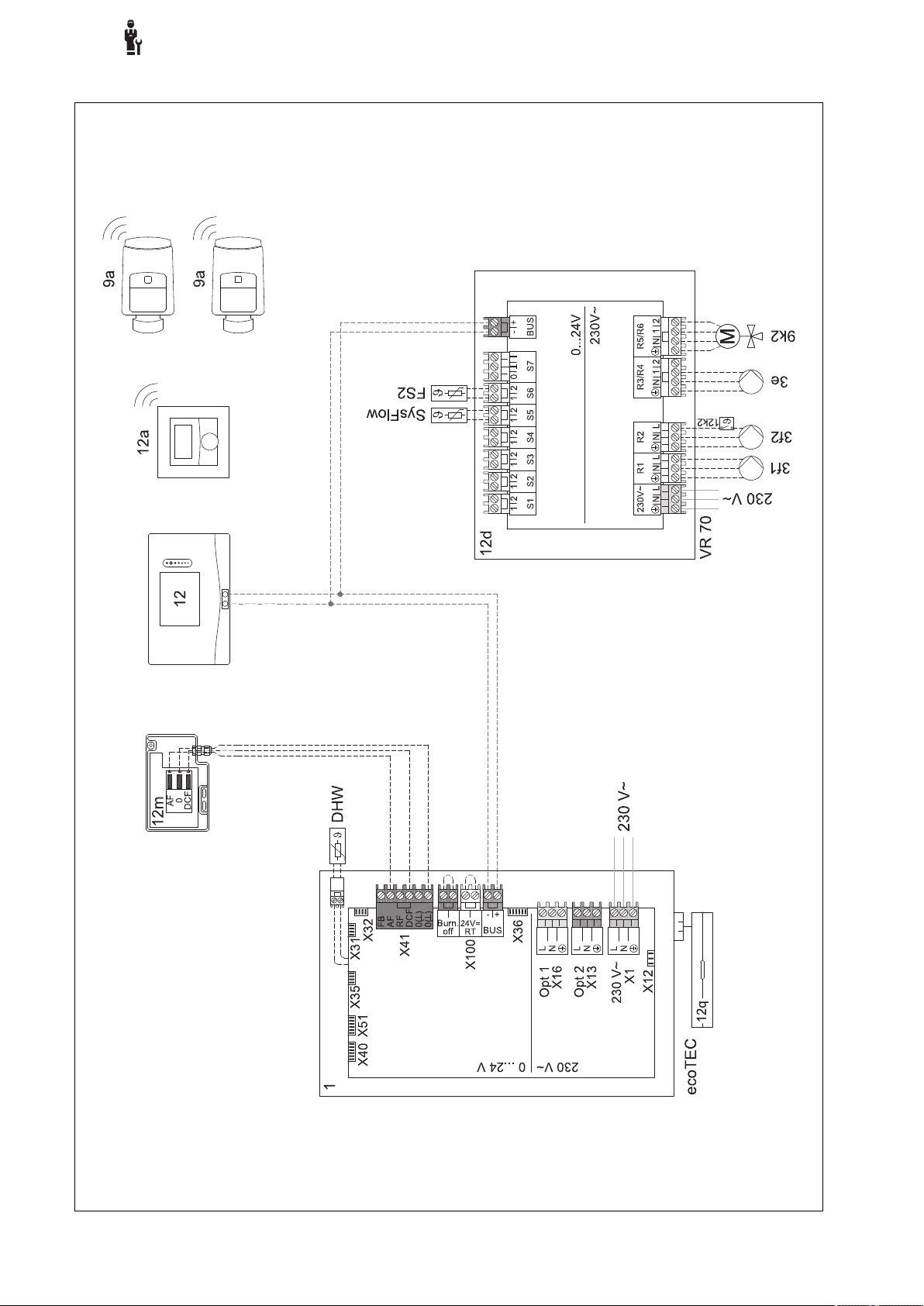
4.9.2.3 Wiring diagram 0020184677
30 Operating and installation instructions sensoCOMFORT 0020287900_00

-- Using the functional modules, basic system diagram, start-up
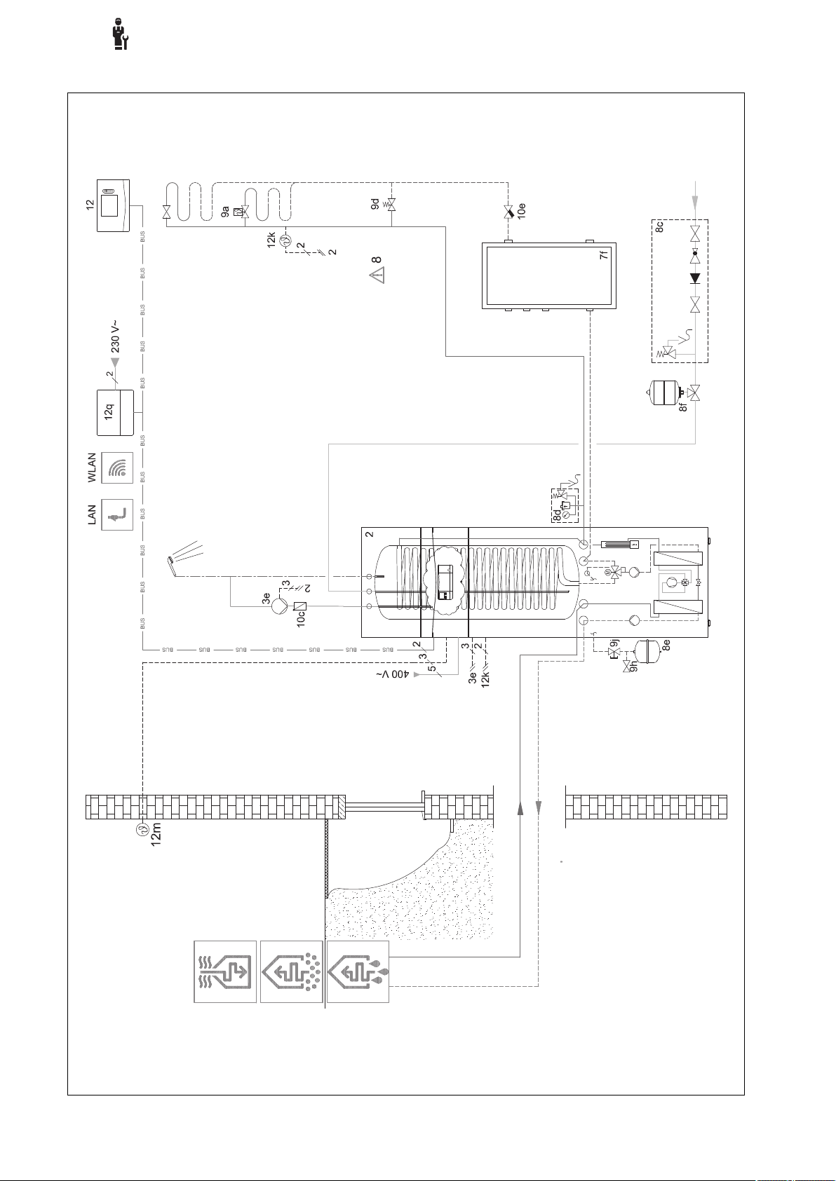
4.9.3 Basic system diagram 0020284121
4.9.3.1 Settings on the system control
Basic system diagram code: 1
FM3 configuration: 1
FM3 MO: Circulation pump
Circuit 1 / Circuit type: Heating
Circuit 1 / Room temp. mod.: Inactive
Circuit 2 / Circuit type: Heating
Circuit 2 / Room temp. mod.: Active or Expanded
Zone 1/ Zone activated: Yes
Zone 1 / Zone assignment: No assignmt
Zone 2/ Zone activated: Yes
Zone 2 / Zone assignment: Control
4
0020287900_00 sensoCOMFORT Operating and installation instructions 31

4
-- Using the functional modules, basic system diagram, start-up
4.9.3.2 Basic system diagram 0020284121
32 Operating and installation instructions sensoCOMFORT 0020287900_00
-- Using the functional modules, basic system diagram, start-up
4.9.3.3 Wiring diagram 0020284121
4
0020287900_00 sensoCOMFORT Operating and installation instructions 33
4
-- Using the functional modules, basic system diagram, start-up
4.9.4 Basic system diagram 0020177912
4.9.4.1 Special features of the system
8: At least 35% of the nominal flow rate must always be able to flow through a reference room without an individual
room temperature control valve.
4.9.4.2 Settings on the system control
Basic system diagram code: 8
Circuit 1 / Room temp. mod.: Active or Expanded
Zone 1 / Zone assignment: Control
4.9.4.3 Settings in the heat pump
Cooling technology: No cooling
34 Operating and installation instructions sensoCOMFORT 0020287900_00
-- Using the functional modules, basic system diagram, start-up
4.9.4.4 Basic system diagram 0020177912
4
0020287900_00 sensoCOMFORT Operating and installation instructions 35

4
-- Using the functional modules, basic system diagram, start-up
4.9.4.5 Wiring diagram 0020177912
36 Operating and installation instructions sensoCOMFORT 0020287900_00

-- Using the functional modules, basic system diagram, start-up
4.9.5 Basic system diagram 0020280010
4.9.5.1 Special features of the system
5: The cylinder temperature cut-out must be installed in a suitable location in order to avoid cylinder temperatures
above 100 °C.
4.9.5.2 Settings on the system control
Basic system diagram code: 1
FM5 configuration: 2
FM5 MO: Anti-legio. pump
Circuit 1 / Circuit type: Heating
Circuit 1 / Room temp. mod.: Active or Expanded
Circuit 2 / Circuit type: Heating
Circuit 2 / Room temp. mod.: Active or Expanded
Circuit 3 / Circuit type: Heating
Circuit 3 / Room temp. mod.: Active or Expanded
Zone 1/ Zone activated: Yes
Zone 1 / Zone assignment: Rem. contr. 1
Zone 2/ Zone activated: Yes
Zone 2 / Zone assignment: Rem. contr. 2
Zone 3/ Zone activated: Yes
Zone 3 / Zone assignment: Control
4
4.9.5.3 Settings at the remote control
Remote control address: (1): 1
Remote control address: (2): 2
0020287900_00 sensoCOMFORT Operating and installation instructions 37

4
-- Using the functional modules, basic system diagram, start-up
4.9.5.4 Basic system diagram 0020280010
38 Operating and installation instructions sensoCOMFORT 0020287900_00

-- Using the functional modules, basic system diagram, start-up
4.9.5.5 Wiring diagram 0020280010
4
0020287900_00 sensoCOMFORT Operating and installation instructions 39

4
-- Using the functional modules, basic system diagram, start-up
4.9.6 Basic system diagram 0020260774
4.9.6.1 Special features of the system
17: Optional component
4.9.6.2 Setting on the system control
Basic system diagram code: 1
FM5 configuration: 6
Circuit 1 / Circuit type: Heating
Circuit 1 / Room temp. mod.: Active or Expanded
Circuit 2 / Circuit type: Heating
Circuit 2 / Room temp. mod.: Active or Expanded
Circuit 3 / Circuit type: Heating
Circuit 3 / Room temp. mod.: Active or Expanded
Zone 1/ Zone activated: Yes
Zone 1 / Zone assignment: Rem. contr. 1
Zone 2/ Zone activated: Yes
Zone 2 / Zone assignment: Rem. contr. 2
Zone 3/ Zone activated: Yes
Zone 3 / Zone assignment: Control
4.9.6.3 Settings at the remote control
Remote control address: (1): 1
Remote control address: (2): 2
40 Operating and installation instructions sensoCOMFORT 0020287900_00

-- Using the functional modules, basic system diagram, start-up
4.9.6.4 Basic system diagram 0020260774
4
0020287900_00 sensoCOMFORT Operating and installation instructions 41

4
-- Using the functional modules, basic system diagram, start-up
4.9.6.5 Wiring diagram 0020260774
42 Operating and installation instructions sensoCOMFORT 0020287900_00

5 -- Start-up
5.1 Prerequisites for starting up
– The system control and outdoor temperature sensor have
been installed and wired.
–
The FM5 functional module is installed and connected in
accordance with configuration 1, 2, 3 or 6, see supplement.
– The FM3 functional modules are installed and connected,
see supplement. A unique address is assigned to each
FM3 functional module via the address switch.
– Start-up of all system components (except for the system
control) is complete.
5.2 Running the installation assistants
The installation assistant is at the Language: query.
The system control's installation assistant takes you through
a list of functions. For each function, you should choose the
set value that is best suited to the heating installation being
installed.
-- Start-up
DHW: The back-up boiler takes over the domestic hot water
mode; the domestic hot water becomes hot and the heating
is cold.
DHW + heat.: The back-up boiler takes over the heating
and domestic hot water mode; the heating and domestic hot
water become hot.
The back-up boiler is not as efficient as the heat pump,
meaning that using only the back-up boiler to generate heat
is expensive.
Troubleshooting (→ Appendix)
6.2 Fault message
with the text of the fault message appears in the
display.
You can find fault messages under: MENU → SETTINGS →
Installer level → Fault history
Troubleshooting (→ Appendix)
6.3 Maintenance message
5
5.2.1 Completing the installation assistant
Once you have gone through the installation assistant, Select the next step. appears on the display
Installation configuration: The installation assistant
switches to the system configuration for the installer level, in
which you can further optimise the heating installation.
Installation start: The installation assistant switches to the
basic display and the heating installation works with the values you have set.
Sensor/actuator test: The installation assistant switches to
the sensor/actuator test function. You can test the sensors
and actuators here.
5.3 Changing the settings later
All settings that you have made via the installation assistant
can be changed again at a later date via the end user or
installer level.
6 Fault and maintenance messages
6.1 Fault How to respond if the heat pump fails
The system control switches to limp home mode, i.e. the
back-up boiler supplies the heating installation with heating
energy. During installation, the competent person has restricted the temperature for limp home mode. You can feel that
the domestic hot water and heating are not becoming very
hot.
You can select one of the following settings until the competent person arrives:
Off: The heating and domestic hot water only become moderately hot.
Heating: The back-up boiler takes over the heating mode;
the heating becomes hot and the domestic hot water is cold.
with the text of the maintenance message appears in the
display.
Maintenance message (→ Appendix)
7 Information about the product
7.1 Observing and storing other applicable documents
▶ Observe all of the instructions that are intended for you
and are enclosed with the components of the installation.
▶ As the end user, keep these instructions and all other
applicable documents safe for future use.
7.2 Validity of the instructions
These instructions apply only to:
– 0020260921
7.3 Data plate
The data plate is located on the rear of the product.
Information on the data
plate
Serial number for identification; 7th to
sensoCOMFORT Product designation
V Rated voltage
mA Rated current
Meaning
16th digits = product article
number
Read the instructions
0020287900_00 sensoCOMFORT Operating and installation instructions 43

7 Information about the product
7.4 Serial number
You can call up the serial numbers under MENU → INFORM-
ATION → Serial number. The 10-digit article number is loc-
ated in the second line.
7.5 CE marking
The CE marking shows that the products comply with the
basic requirements of the applicable directives as stated on
the declaration of conformity.
The declaration of conformity can be viewed at the manufacturer's site.
7.6 Guarantee and customer service
7.6.1 Guarantee
You can find information about the manufacturer's guarantee
in the Country specifics.
7.6.2 Customer service
The contact details for our customer service are provided on
the back page or on our website.
7.9 Technical data – System control
Rated voltage
Rated surge voltage
Pollution degree
Rated current
Supply line cross-section
IP rating
Protection class
Temperature for the ball pressure test
Maximum permitted environmental tem-
perature
Current room air hum.
Mode of operation
Height
Width
Depth
9 to 24 V
330 V
2
< 50 mA
0.75 … 1.5 mm²
IP 20
III
75 ℃
0 … 60 ℃
35 … 95 %
Type 1
109 mm
175 mm
26 mm
7.7 Recycling and disposal
▶ The competent person who installed your product is re-
sponsible for the disposal of the packaging.
If the product is labelled with this mark:
▶ In this case, do not dispose of the product with the
household waste.
▶ Instead, hand in the product to a collection centre for
waste electrical or electronic equipment.
----- Packaging -----------------
▶ Dispose of the packaging correctly.
▶ Observe all relevant regulations.
7.8 Product data in accordance with EU Ordinance no. 811/2013, 812/2013
On units with integrated weather-compensated controls, including a room thermostat function that can be activated, the
seasonal room-heating efficiency always includes the correction factor for control technology class VI. The seasonal
room-heating efficiency may deviate if this function is deactivated.
Temperature control class
Contribution to the seasonal room-heat-
ing energy efficiency ɳs
VI
4.0 %
44 Operating and installation instructions sensoCOMFORT 0020287900_00

Appendix
Appendix
A Troubleshooting, maintenance message
A.1 Troubleshooting
Symptom Possible cause Measure
Display remains dark Software error 1. Press and hold the button on the top right of the system con-
No changes in the display can
be made via the control elements
Display: Button lock activated,
it is not possible to change the
settings or values
Display: Mode: Back-up boiler
if fault occurs Heat pump (call
the comp. person), insufficient
heating-up of the heating and
the domestic hot water
Display: F. Boiler fault, the
specific fault code (e.g. F.33)
with the specific boiler is shown
in the display
Display: You do not understand
the set language
Software error 1. Press and hold the button on the top right of the system con-
Button lock is active ▶ Press the button on the top right of the system control for ap-
Heat pump does not work 1. Inform the competent person.
Boiler fault 1. Reset the boiler by first selecting Reset and then Yes.
Incorrect language set 1.
trol for longer than five seconds in order to force a restart.
2. Switch off the mains switch on all heat generators for approx.
1 minute and then switch them on again.
3. If the fault message persists, inform the competent person.
trol for longer than five seconds in order to force a restart.
2. Switch off the mains switch on all heat generators for approx.
1 minute and then switch them on again.
3. If the fault message persists, inform the competent person.
prox one second in order to deactivate the button lock.
2. Select the setting for limp home mode until the competent
person arrives.
3. You can find more detailed explanations under Faults, fault
messages and maintenance messages (→ Page 43).
2. If the fault message persists, inform the competent person.
Press twice.
2.
Select the last menu item ( SETTINGS) and confirm by
pressing .
3.
Under SETTINGS, select the second menu item and
confirm by pressing .
4. Select the language that you understand and confirm by
pressing .
A.2 Maintenance messages
# Message Description Maintenance work Interval
1 Water defi-
ciency: Follow
the instructions
in the heat gen.
The water pressure is too low in
the heating installation.
Refer to the operating instructions for the relevant heat generator for information on filling
with water
See the operating instructions
for the heat generator
B -- Troubleshooting, maintenance message
B.1 Troubleshooting
Symptom Possible cause Measure
Display remains dark Software error 1. Press and hold the button on the top right of the system con-
No power supply on the heat
generator
The product is defective ▶ Replace the product.
No changes in the display can
be made via the control elements
Software error ▶ Switch the mains switch on the heat generator that feeds the
The product is defective ▶ Replace the product.
trol for longer than five seconds in order to force a restart.
2. Switch the mains switch on the heat generator that feeds the
system control off and back on again.
▶ Re-establish the power supply to the heat generator; this is the
same power supply that feeds the system control.
system control off and back on again.
0020287900_00 sensoCOMFORT Operating and installation instructions 45

Appendix
Symptom Possible cause Measure
Heat generator continues to
heat once the room temperature
has been reached
The heating installation remains
in domestic hot water mode
Only one of several heating
circuits is displayed
It is not possible to switch to the
installer level
B.2 Troubleshooting
Message Possible cause Measure
Ventilation unit communication
interrupted
HP control module communication interrupted
Outdoor temperature sensor
signal invalid
Heat generator 1 communication interrupted *,
* Can be heat generator 1 to 8
FM3 address 1 communication
interrupted *,
* Can be address 1 to 3
FM5 communication interrupted The cable is defective ▶ Replace the cable.
Remote control 1 communication interrupted *,
* Can be address 1 to 3
Domestic hot water station com-
munication interrupted
Solar pump station communication interrupted
FM3 configuration [1] not correct *,
* Can be address 1 to 3
Mixer module no longer suppor-
ted
Solar module no longer suppor-
ted
Remote control no longer sup-
ported
Basic system diagram code not
correct
Remote control 1 missing *,
* Can be remote control 1 or 2
Current basic system diagram
does not support FM5
FM3 missing Missing FM3 ▶ Connect the FM3.
DHW temperature sensor S1
missing at FM3
Solar pump 1 reports faults *, *
Solar pump 1 or 2
Incorrect value in the Room
temp. mod.: or Zone assignment: function
Heat generator cannot reach
the max. target flow temperature
Heating circuits inactive ▶ In the Circuit type: function, define the required function for
You do not know the code for
the installer level
Incorrect plug connection ▶ Check the plug connection.
The cable is defective ▶
Incorrect plug connection ▶ Check the plug connection.
The cable is defective ▶ Replace the cable.
Outdoor temperature sensor
defective
The cable is defective ▶ Replace the cable.
Incorrect plug connection ▶ Check the plug connection.
The cable is defective ▶ Replace the cable.
Incorrect plug connection ▶ Check the plug connection.
Incorrect plug connection ▶ Check the plug connection.
The cable is defective ▶ Replace the cable.
Incorrect plug connection ▶ Check the plug connection.
The cable is defective ▶ Replace the cable.
Incorrect plug connection ▶ Check the plug connection.
The cable is defective ▶ Replace the cable.
Incorrect plug connection ▶ Check the plug connection.
Incorrect set value for the FM3 ▶ Set the correct set value for the FM3.
Unsuitable module connected ▶ Install a module that the control supports.
Unsuitable module connected ▶ Install a module that the control supports.
Unsuitable module connected ▶ Install a module that the control supports.
Incorrectly selected basic system diagram code
Missing remote control ▶ Connect the remote control.
FM5 connected in the heating
installation
Incorrectly selected basic system diagram code
Domestic hot water temperature
sensor S1 not connected
Fault in the solar pump ▶ Check the solar pump.
1. In the Room temp. mod.: function, set the value Active or
Expanded.
2. In the zone in which the system control is installed, assign
the system control's address in the Zone assignment: function.
▶ Reduce the set value in the Max. target flow temperature:°C
function.
the heating circuit.
▶ Reset the system control to the factory setting. All set values
will be lost.
Replace the cable.
▶ Replace the outdoor temperature sensor.
▶ Set the correct basic system diagram code.
▶ Remove the FM5 from the heating installation.
▶ Set the correct basic system diagram code.
▶ Connect the domestic hot water temperature sensor to the
FM3.
46 Operating and installation instructions sensoCOMFORT 0020287900_00
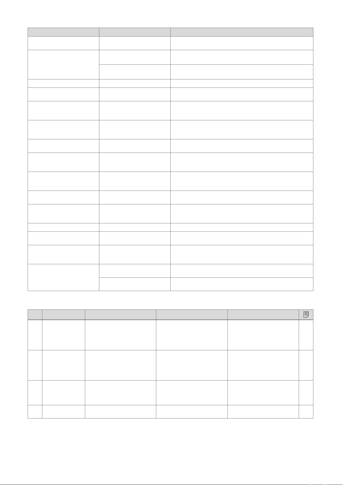
Message Possible cause Measure
Shift-load cylinder no longer
supported
HP control module MO2 configuration not correct
FM5 configuration not correct Incorrect set value for the FM5 ▶ Set the correct set value for the FM5.
Cascade not supported Incorrectly selected system dia-
FM3 configuration [1] MO not
correct *, * Can be address 1 to
3
FM5 configuration MO not correct
Room temp. sensor signal on
control invalid
Room temp. sensor signal on
remote control 1 invalid *, * Can
be address 1 to 3
S1 sensor signal at FM3 address 1 invalid *, * Can be S1 to
7 and address 1 to 3
S1 sensor signal at FM5 invalid
*, * Can be S1 to S13
Heat generator 1 reports faults
*, * Can be heat generator 1 to
8
Ventilation unit reports faults Ventilation unit fault ▶ See instructions for the ventilation unit.
HP control module reports faults Fault in the heat pump control
Assignment of remote control 1
missing *, * Can be address 1
to 3
Zone activation missing A zone that is in use is not yet
Unsuitable cylinder connected ▶ Remove the cylinder from the heating installation.
Incorrectly connected FM3 1. Remove the FM3.
2. Select a suitable configuration.
Incorrectly connected FM5 1. Remove the FM5.
2. Select another configuration.
▶ Set the correct system diagram that contains cascades.
gram
Incorrect component selection
for the MO
Incorrect component selection
for the MO
Room temperature sensor defective
Room temperature sensor defective
Sensor defective ▶ Replace the sensor.
Sensor defective ▶ Replace the sensor.
Fault in the heat generator ▶ See the instructions for the heat generator displayed.
▶ Select the component in the FM3 MO function that is appropri-
ate for the connected component on the FM3's multi-function
output.
▶ Select the component in the FM5 MO function that is appropri-
ate for the connected component on the FM5's multi-function
output.
▶ Replace the control.
▶ Replace the remote control.
▶ Replace the heat pump control module.
module
The assignment of remote con-
trol 1 to the zone is missing.
▶ Assign the correct address to the remote control in the Zone
assignment: function.
▶ In the Zone activated: function, select the value Yes.
activated.
Heating circuits inactive ▶ In the Circuit type: function, define the required function for
the heating circuit.
Appendix
B.3 Maintenance messages
# Message Description Maintenance work Interval
1 Heat generator
1 requires maintenance *, * Can
be heat generator
1 to 8
2 Ventilation unit
requires maintenance
3 Water defi-
ciency: Follow
the instructions
in the heat gen.
4 Maintenance
Contact:
The heat generator requires
maintenance work.
The ventilation unit requires
maintenance work.
The water pressure is too low in
the heating installation.
Date on which maintenance is
due for the heating installation.
Refer to the operating or installation instructions for the relevant heat generator for information on the maintenance work
required
Refer to the operating or installation instructions for the relevant ventilation unit for information on the maintenance work
required
Water deficiency: Follow the instructions in the heat generator
Carry out the required maintenance work
See the operating or installation
instructions for the heat generator
See the operating or installation
instructions for the ventilation
unit
See the operating or installation
instructions for the heat generator
Date entered in the control
0020287900_00 sensoCOMFORT Operating and installation instructions 47

Index
Index
A
Article number ..................................................................... 44
C
CE marking..........................................................................44
Competent person.................................................................2
Connecting a system control to the ventilation unit............. 15
Control elements ................................................................... 4
D
Display...................................................................................4
Disposal...............................................................................44
Documents ..........................................................................43
F
Fault ....................................................................................43
Faults...................................................................................43
Frost ......................................................................................2
I
Intended use.......................................................................... 2
L
Lines, maximum length .......................................................15
Lines, minimum cross-section .............................................15
Lines, selecting.................................................................... 15
M
Maintenance........................................................................ 43
O
Operating and display functions ............................................ 5
P
Prerequisites for starting up the heating installation ........... 43
Prerequisites, start-up ......................................................... 43
Preventing a malfunction....................................................... 3
Q
Qualification...........................................................................2
R
Reading the article number ................................................. 44
Reading the serial number .................................................. 44
Recycling.............................................................................44
Regulations ........................................................................... 2
Running the installation assistants...................................... 43
S
Serial number......................................................................44
Setting the heat curve ........................................................... 4
48 Operating and installation instructions sensoCOMFORT 0020287900_00

Contenido
Manual de uso e instalación
Contenido
1 Seguridad ........................................................... 50
1.1 Utilización adecuada............................................ 50
1.2 Información general de seguridad ....................... 50
1.3 -- Seguridad/Normativa.................................. 50
2 Descripción del producto ................................. 51
2.1 ¿Qué nomenclatura se utiliza?............................ 51
2.2 ¿Para qué sirve la función de protección
contra heladas?................................................... 51
2.3 ¿Qué significan las siguientes temperaturas?..... 51
2.4 ¿Qué es una zona? ............................................. 51
2.5 ¿Qué es la circulación? ....................................... 51
2.6 ¿Qué es una regulación de valor fijo? ................. 51
2.7 ¿Qué significa período?....................................... 51
2.8 ¿Para qué sirve el gestor híbrido? ...................... 51
2.9 Prevención de funcionamientos erróneos ........... 52
2.10 Ajustar la curva de calefacción............................ 52
2.11 Pantalla, paneles de mando y símbolos.............. 52
2.12 Funciones de uso y visualización ........................ 53
7 Información sobre el producto......................... 91
7.1 Consulta y conservación de la documentación
adicional............................................................... 91
7.2 Validez de las instrucciones ................................ 91
7.3 Placa de características....................................... 91
7.4 Número de serie .................................................. 92
7.5 Homologación CE................................................ 92
7.6 Garantía y servicio de atención al cliente ............ 92
7.7 Reciclaje y eliminación ........................................ 92
7.8 Datos del producto según la ordenanza de la
UE n.º 811/2013, 812/2013 ................................. 92
7.9 Datos técnicos - Regulador del sistema.............. 92
Anexo .................................................................................93
A Solución de problemas, mensaje de
mantenimiento ................................................... 93
A.1 Solución de averías ............................................. 93
A.2 Mensajes de mantenimiento................................ 93
B -- Solución de averías, solución de
problemas, mensaje de mantenimiento .......... 94
B.1 Solución de averías ............................................. 94
B.2 Eliminación del fallo ............................................. 94
B.3 Mensajes de mantenimiento................................ 96
Índice de palabras clave ...................................................97
3 -- Instalación eléctrica, montaje.................. 63
3.1 Selección de los cables ....................................... 63
3.2 Conexión del regulador del sistema al equipo
de ventilación....................................................... 63
3.3 Montaje del regulador del sistema y sensor de
temperatura exterior ............................................ 64
4 -- Uso de los módulos de función,
esquema del sistema, puesta en marcha........ 67
4.1 Sistema sin módulos de función.......................... 67
4.2 Sistema con módulo de función FM3 .................. 67
4.3 Sistema con módulos de función FM5 y FM3 ..... 68
4.4 Posibilidad de uso de los módulos de función..... 68
4.5 Asignación de conexión del módulo de función
FM5...................................................................... 69
4.6 Asignación de conexión del módulo de función
FM3...................................................................... 70
4.7 Ajustes del código del esquema del sistema....... 71
4.8 Combinaciones del esquema del sistema y
configuración de los módulos de función ............ 73
4.9 Esquema del sistema y esquema de
conexiones........................................................... 74
5 -- Puesta en marcha ..................................... 91
5.1 Requisitos para la puesta en marcha.................. 91
5.2 Ejecución del asistente de instalación................. 91
5.3 Modificación posterior de ajustes ........................ 91
6 Fallo, mensajes de error y mantenimiento...... 91
6.1 Avería .................................................................. 91
6.2 Mensaje de error.................................................. 91
6.3 Mensaje de mantenimiento ................................. 91
0020287900_00 sensoCOMFORT Manual de uso e instalación 49
1 Seguridad
1 Seguridad
1.1 Utilización adecuada
Su uso incorrecto o utilización inadecuada
puede provocar daños en el producto u otros
bienes materiales.
El producto está diseñado para regular una
instalación de calefacción con generadores
de calor del mismo fabricante con interfaz
eBUS.
En función del sistema instalado, el regulador
del sistema regula:
– Calefacción
– Refrigeración
– Ventilación
– Preparación de agua caliente sanitaria
– Recirculación
La utilización adecuada implica:
– la observación de toda la documentación
adicional del producto y de todos los demás componentes de la instalación
– Realizar la instalación y el montaje con-
forme a la homologación del producto y
del sistema.
La utilización adecuada implica, además,
realizar la instalación conforme al código IP.
Este producto puede ser utilizado por niños
a partir de 8 años, así como por personas
con capacidades físicas, sensoriales o mentales disminuidas o con falta de experiencia
y conocimientos, si son vigilados o han sido
instruidos respecto al uso seguro del aparato y comprenden los peligros derivados del
mismo. No deje que los niños jueguen con el
producto. No permita que los niños efectúen
la limpieza y el mantenimiento sin vigilancia.
Una utilización que no se corresponda con
o que vaya más allá de lo descrito en las
presentes instrucciones se considera inadecuada.
1.2 Información general de seguridad
1.2.1 Peligro por cualificación insuficiente
Las siguientes tareas solo deben ser llevadas
a cabo por profesionales autorizados que
estén debidamente cualificados:
– Montaje
– Desmontaje
– Instalación
– Puesta en marcha
– Puesta fuera de servicio
▶ Proceda según el estado actual de la téc-
nica.
Los trabajos y funciones que solo pueden
ser realizados o ajustados por un profesional
autorizado están marcados con el símbolo
.
1.2.2 Peligro por un uso incorrecto
El uso incorrecto puede poner en peligro
tanto a usted como a otras personas y ocasionar daños materiales.
▶ Lea atentamente las presentes instruccio-
nes y toda la documentación adicional, especialmente el capítulo "Seguridad" y las
notas de advertencia.
▶ Como usuario, realice solo aquellas ope-
raciones a las que se refieren las presentes instrucciones y que no están marcadas
con el símbolo .
1.3 -- Seguridad/Normativa
1.3.1 Riesgo de daños materiales causados por heladas
▶
No instale el producto en estancias con
riesgo de heladas.
1.3.2 Disposiciones (directivas, leyes, normas)
▶ Observe las disposiciones, normas, directi-
vas, ordenanzas y leyes nacionales.
50 Manual de uso e instalación sensoCOMFORT 0020287900_00
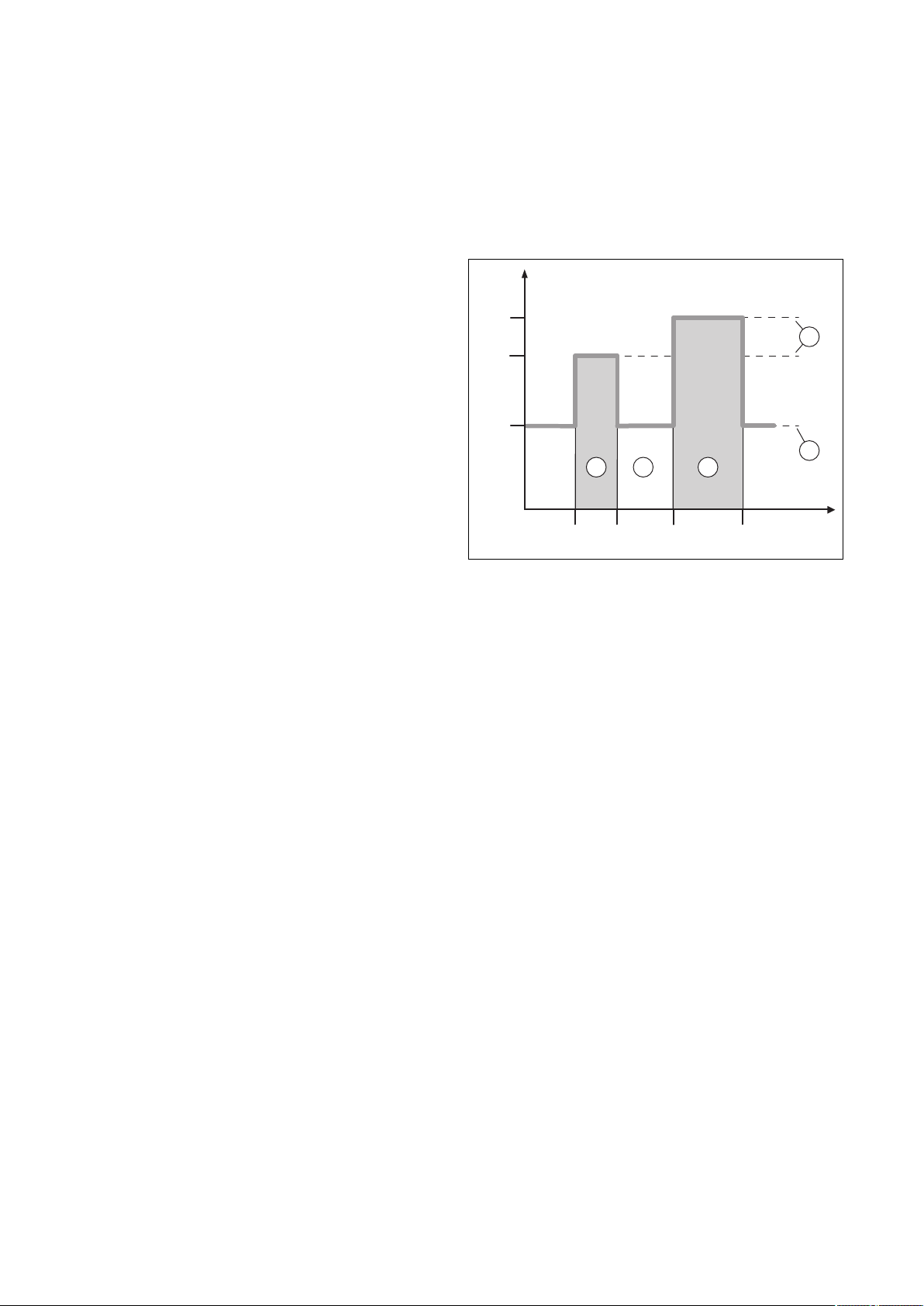
Descripción del producto 2
24 °C
18:0016:30
22:30
16 °C
21 °C
20:00
A
B
5
1
2
3
4
2 Descripción del producto
2.1 ¿Qué nomenclatura se utiliza?
– Regulador del sistema: en lugar de VRC 720
– Mando a distancia: en lugar de VR 92
– Módulo de función FM3 o FM3: en lugar de VR 70
– Módulo de función FM5 o FM5: en lugar de VR 71
2.2 ¿Para qué sirve la función de protección contra heladas?
La función de protección antihielo protege la instalación de
calefacción y la vivienda de los daños causados por las heladas.
Con temperaturas exteriores
– que descienden por debajo de 4 °C durante más de 4
horas, el regulador del sistema conecta el generador
de calor y regula la temperatura nominal interior a 5 °C
como mínimo.
– por encima de 4 °C, el regulador no conecta el genera-
dor de calor pero controla la temperatura exterior.
2.3 ¿Qué significan las siguientes temperaturas?
2.6 ¿Qué es una regulación de valor fijo?
El regulador del sistema regula la temperatura de ida a dos
temperaturas fijas ajustadas que dependen de la temperatura ambiente o de la temperatura exterior. Esta regulación
es apropiada, entre otras cosas, para una cortina de aire en
la puerta o una calefacción de piscinas.
2.7 ¿Qué significa período?
Ejemplo, modo calefacción en el modo: temporizado
La temperatura deseada es la temperatura a la que se deben calentar las estancias.
La temperatura de reducción es la temperatura mínima
que debe alcanzarse en las estancias fuera de los períodos.
La temperatura de ida es la temperatura con la que el agua
de calefacción abandona el generador de calor.
2.4 ¿Qué es una zona?
Un edificio puede estar dividido en varias áreas que se denominan zonas. Cada zona puede tener un requisito distinto
a la instalación de calefacción.
Ejemplos para la división en zonas:
– En una casa hay calefacción por suelo radiante (zona 1)
y un radiador plano (zona 2).
– En una casa hay varias unidades habitables indepen-
dientes. Cada unidad habitable recibe una zona propia.
2.5 ¿Qué es la circulación?
En el conducto de agua caliente sanitaria se conecta un conducto de agua adicional y forma un circuito con el acumulador de agua caliente sanitaria. La circulación permanente del
agua caliente sanitaria está garantizada por una bomba de
recirculación, por lo que agua caliente está disponible de inmediato, incluso en caso de tomas de agua muy alejadas.
A Hora
B Temperatura
1 Temperatura deseada
2 Temperatura de des-
censo
3 Período 2
4 fuera de los períodos
5 Período 1
Puede dividir un día en varios períodos (3) y (5). Cada período puede abarcar un período individual. Los períodos no
deben solaparse. Puede asignar una temperatura deseada
distinta (1) a cada período.
Ejemplo:
16:30 hasta 18:00 h; 21 °C
20:00 hasta 22:30 h; 24 °C
El regulador del sistema regula las estancias a la tempera-
tura deseada dentro del período. Fuera de los períodos (4),
el regulador del sistema regula las estancias a la temperatura de reducción baja ajustada (2).
2.8 ¿Para qué sirve el gestor híbrido?
El gestor híbrido calcula si la bomba de calor o la caldera
adicional cubre la demanda de calor de forma más rentable.
Los criterios de decisión son las tarifas ajustadas en relación
con la demanda de calor.
Para que la bomba de calor y la caldera adicional puedan
trabajar de modo eficaz, deben ajustarse correctamente
las tarifas. Véase la tabla Punto del menú AJUSTES
(→ Página 56). De lo contrario, se pueden producir costes
mayores.
0020287900_00 sensoCOMFORT Manual de uso e instalación 51
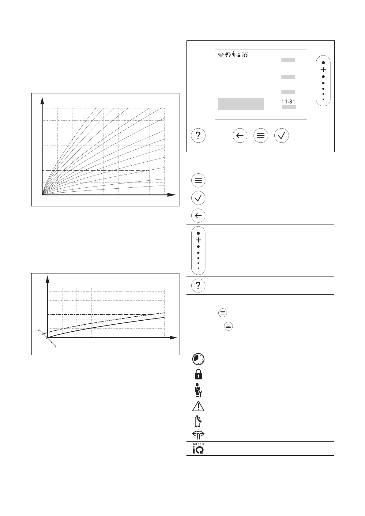
2 Descripción del producto
A
B
15 10 5 0 -5 -10 -15 -20
20
30
40
50
60
70
80
90
1.2
1.5
1.822.533.54
0.8
1.0
0.4
0.2
0.1
0.6
A
B
CD
18
22
20
0.4
70
60
50
40
30
15 10 5 0 -5 -10 -15 -20
ĮİŰ
ĬĪƀ
ĬįŀĪ
ƀ
īĬƀ
2.9 Prevención de funcionamientos erróneos
▶ No cubra el regulador del sistema con muebles, cortinas
u otros objetos.
▶ Si el regulador del sistema está montado en el salón,
abra todas las válvulas de termostato del serpentín de
esta habitación por completo.
2.10 Ajustar la curva de calefacción
2.11 Pantalla, paneles de mando y símbolos
2.11.1 Elementos de mando
– Activación del menú
– Volver a la pantalla básica
– Confirmar selección/cambio
– Guardar los valores de ajuste
A Temperatura exterior °C B Temperatura de ida
La figura muestra las curvas de calefacción posibles desde
0,1 hasta 4,0 para una temperatura nominal interior de
20 °C. Cuando se selecciona, por ejemplo, la curva de
calefacción 0,4, si la temperatura exterior es de -15 °C, la
calefacción se regula a una temperatura de impulso de 40
°C.
A Temperatura exterior °C
B Temperatura de ida
Si se ha seleccionado la curva de calefacción 0,4 y la temperatura nominal interior especificada es de 21 °C, la curva
de calefacción se desplaza tal y como se muestra en la figura. La curva de calefacción se desplaza en paralelo sobre
el eje a, inclinado 45°, según el valor de la consigna de temperatura ambiente. Si la temperatura exterior es de −15 °C,
la regulación ajusta una temperatura de ida de 45 °C.
52 Manual de uso e instalación sensoCOMFORT 0020287900_00
nominal °C
nominal °C
C Temperatura nominal
interior °C
D Eje a
– Un nivel atrás
– Cancelar la entrada
– Navegar por la estructura del menú
– Disminución o aumento del valor de ajuste
– Navegar a números/letras individuales
– Abrir Ayuda
– Abrir Asistente de programa de tiempos
Los paneles de mandos activos se iluminan en verde.
Pulsar 1 vez : accederá a la pantalla básica.
Pulsar 2 veces : accederá al menú.
2.11.2 Símbolos
Calefacción temporizada activa
Bloqueo de teclas activo
Mantenimiento pendiente
Error en la instalación de calefacción
Contactar con el profesional autorizado
Reducción de ruido activa
Modo de calefacción más eficiente activo

Descripción del producto 2
2.12 Funciones de uso y visualización
Indicación
Las funciones descritas en el presente capítulo no están disponibles en todas las configuraciones del sistema.
Para acceder al menú, pulse 2 veces .
2.12.1 Punto del menú REGULACIÓN
MENÚ → REGULACIÓN
→ Zona
→ Nombre de la zona Cambiar el nombre ajustado de fábrica Zona 1
→ Calefacción → Modo: → Manual → Temperatura deseada: °C
Mantenimiento ininterrumpido de la temperatura deseada
→ Tiempo contr. → Planificador semanal
→ Temperatura de reducción: °C
Planificador semanal: se pueden ajustar hasta 12 períodos y temperaturas deseadas por día
El profesional autorizado ajusta el comportamiento de la instalación de calefacción fuera de los pe-
ríodos en la función Modo de noche:.
En Modo de noche: significa:
– Eco: la calefacción está desconectada fuera de los períodos. La protección contra heladas está
activada.
– Normal: La temperatura de reducción se aplica fuera de los períodos.
Temperatura deseada: °C: se aplica dentro de los períodos
→ Descon.
La calefacción está desconectada, el agua caliente sanitaria continúa estando disponible, la protección contra heladas está activada
→ Refrigeración → Modo: → Manual → Temperatura deseada: °C
Mantenimiento ininterrumpido de la temperatura deseada
→ Tiempo contr. → Planificador semanal
→ Temperatura deseada: °C
Planificador semanal: se pueden ajustar hasta 12 períodos por día, fuera de los períodos, el enfriamiento está desconectado
Temperatura deseada: °C: se aplica dentro de los períodos
Fuera de los períodos, el enfriamiento está desconectado
→ Descon.
El enfriamiento está desconectado, el agua caliente sanitaria continúa estando disponible
→ Ausencia → Todos: se aplica para todas las zonas en el período establecido
→ Zona: se aplica para la zona seleccionada en el período establecido
El modo de calefacción y de agua caliente sanitaria están desconectados, la ventilación funciona en
el nivel más bajo, la protección contra heladas está activada
→ Refrig. durante unos días El modo refrigeración se activa en el período establecido, el modo refrigeración y la temperatura
→ Reg. valor fijo circuito 1
→ Calefacción → Modo: → Manual
deseada se toman de la función Refrigeración
Mantenimiento ininterrumpido de la Temp. nom. ida, deseada: °C, que ha ajustado el profesional
autorizado.
→ Tiempo contr. → Planificador semanal
Planificador semanal: se pueden ajustar hasta 12 períodos por día
Dentro de los períodos se aplica la Temp. nom. ida, deseada: °C.
Fuera de los períodos se aplica la Temp. nom. ida, noche: °C o el circuito de calefacción está des-
conectado.
Con una Temp. nom. ida, noche: °C = 0 °C, la protección contra heladas ya no está garantizada.
El profesional autorizado ajusta las dos temperaturas.
→ Descon.
El circuito de calefacción está desactivado.
0020287900_00 sensoCOMFORT Manual de uso e instalación 53
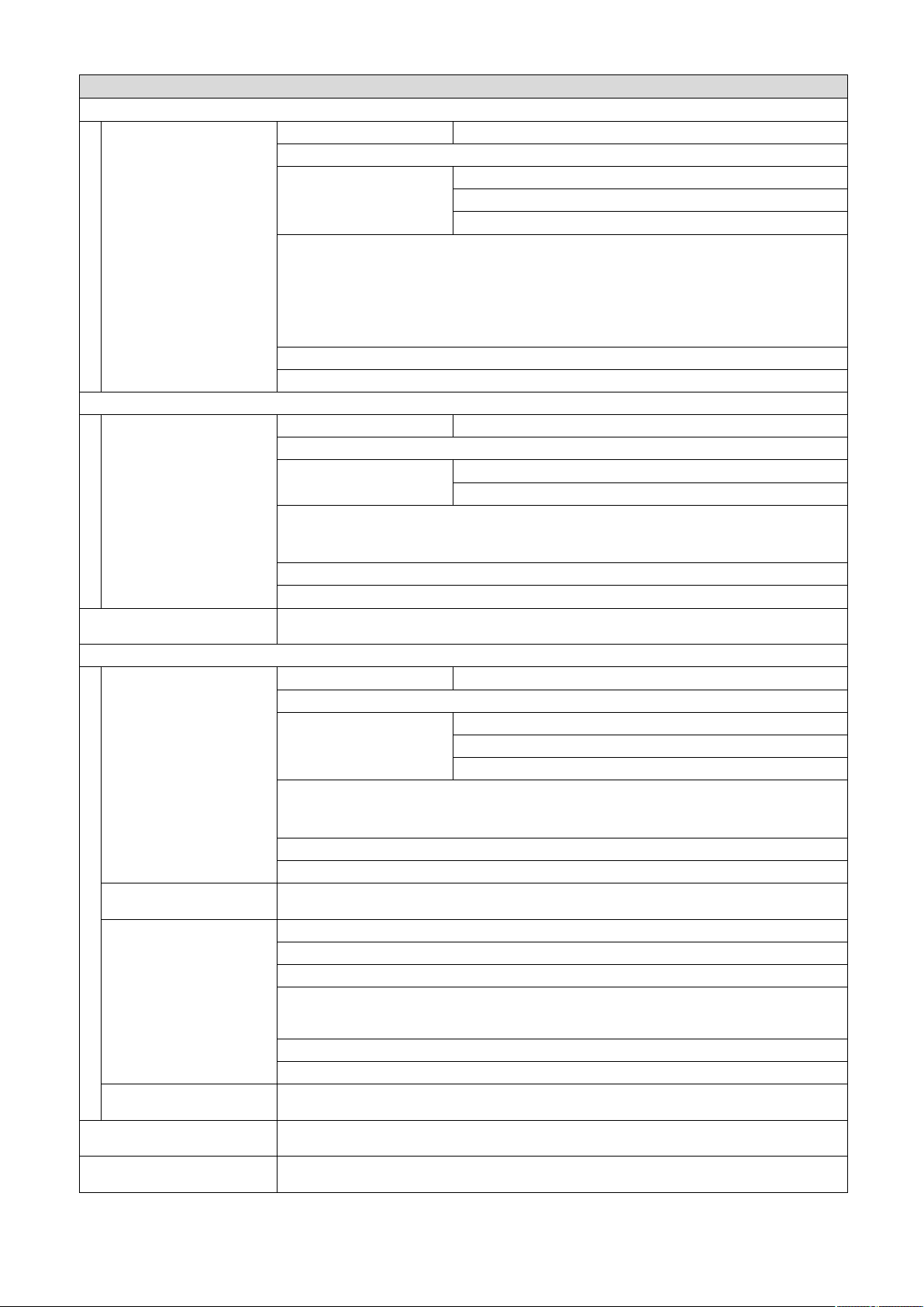
2 Descripción del producto
MENÚ → REGULACIÓN
→ Agua caliente
→ Modo: → Manual → Temperatura de agua caliente sanitaria
Mantenimiento ininterrumpido de la temperatura de agua caliente sanitaria
→ Tiempo contr. → Planificador semanal ACS
→ Temperatura ACS: °C
→ Planificador semana circulación
Planificador semanal ACS: se pueden ajustar hasta 3 períodos por día
Temperatura ACS: °C: se aplica dentro de los períodos
Fuera de los períodos, el modo de agua caliente sanitaria está desconectado
Planificador semana circulación: se pueden ajustar hasta 3 períodos por día
Dentro de los períodos, la bomba de recirculación bombea agua caliente hacia las tomas de agua
Fuera de los períodos, la bomba de recirculación está desconectada
→ Descon.
El modo de agua caliente sanitaria está desactivado
→ Circuito ACS 1
→ Modo: → Manual → Temperatura ACS: °C
Mantenimiento ininterrumpido de la temperatura de agua caliente sanitaria
→ Tiempo contr. → Planificador semanal ACS
→ Temperatura ACS: °C
Planificador semanal ACS: se pueden ajustar hasta 3 períodos por día
Temperatura ACS: °C: se aplica dentro de los períodos
Fuera de los períodos, el modo de agua caliente sanitaria está desconectado
→ Descon.
El modo de agua caliente sanitaria está desactivado
→ Agua caliente sanitaria rápida
→ Ventilación
→ Modo: → Normal → Nivel ventilación normal:
→ Sensor calidad aire 1:
ppm
→ Recuperación del calor: → Conect.
→ Límite calidad del aire:
ppm
→ Ventilación intensiva El modo calefacción está desconectado durante 30 minutos y, si está disponible, la unidad de venti-
→ Prot. humedad → Humedad del aire máx.: %rel: Si se supera el valor, se conecta el deshumidificador. Si no se
Calentamiento único del agua en el acumulador
Ventilación ininterrumpida con el nivel de ventilación: Normal
→ Tiempo contr. → Planificador semanal
→ Nivel ventilación normal:
→ Nivel ventilación reducido:
Planificador semanal: se pueden ajustar hasta 12 períodos por día
Nivel ventilación normal:: se aplica dentro de los períodos
Nivel ventilación reducido:: se aplica fuera de los períodos
→ Reducido
Ventilación ininterrumpida con el nivel de ventilación: Reducido
Mide el contenido de CO2del aire de la habitación
Recuperación ininterrumpida del calor del aire de extracción
→ Auto
Comprobación interna para ver si el aire exterior se conduce a través de la recuperación de calor
o directamente hacia la sala de estar. Véanse las Instrucciones de funcionamiento de la unidad de
ventilación doméstica.
→ Descon.
La recuperación de calor está desactivada
La unidad de ventilación doméstica mantiene el contenido de CO2del aire de la habitación por debajo del valor ajustado.
lación doméstica funciona al máximo nivel de ventilación.
alcanza el valor mínimo, se desconecta el deshumidificador.
54 Manual de uso e instalación sensoCOMFORT 0020287900_00
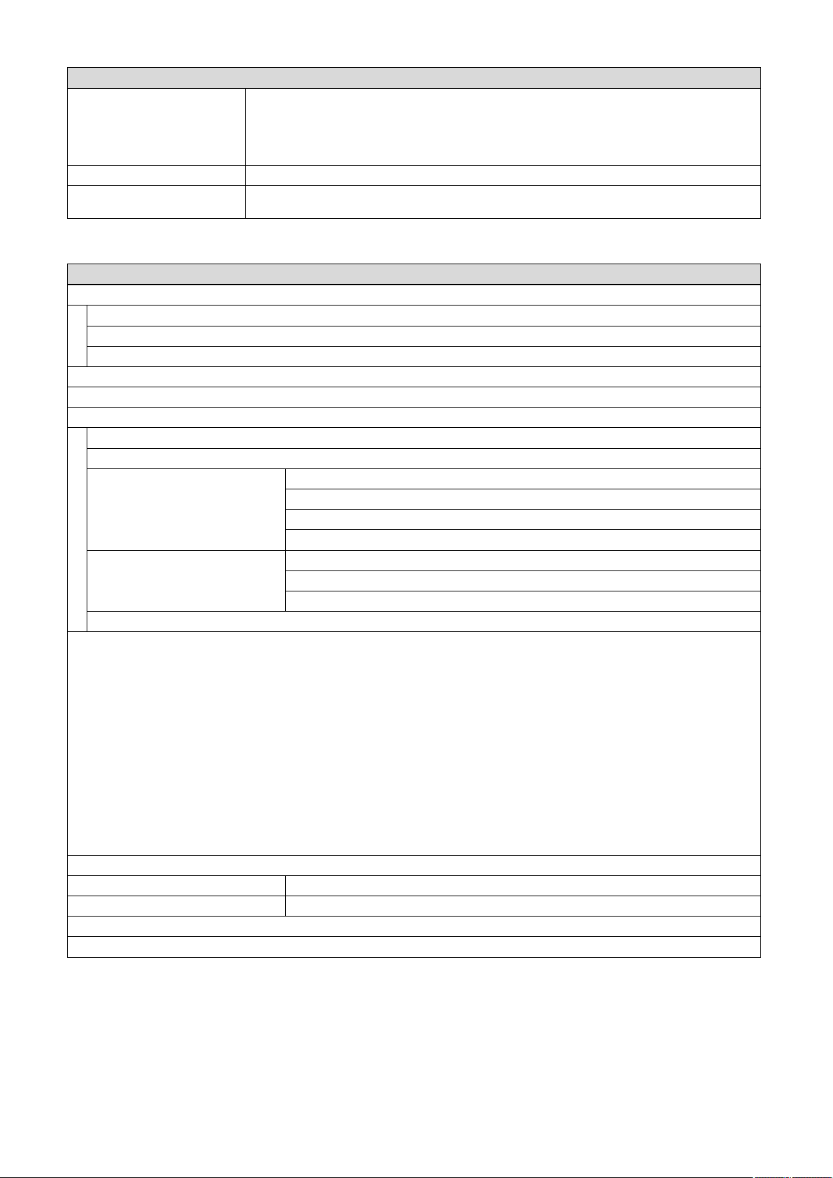
Descripción del producto 2
MENÚ → REGULACIÓN
→ Asistente del programa de
tiempos
→ Green iQ: Conexión del modo calefacción más eficiente energéticamente, si su instalación lo soporta.
→ CALEFACCIÓN PARADA
2.12.2 Punto del menú INFORMACIÓN
MENÚ → INFORMACIÓN
→ Temperaturas actuales
→ Zona
→ Temperatura del ACS
→ Circuito ACS 1
→ Presión del agua: bar
→ Humedad atmosf. actual
→ Datos energéticos
→ Producción solar
→ Aportación renovable
→ Consumo eléctrico → Calefacción
→ Consumo de combustible → Calefacción
→ Recuperación de calor
Indicador de consumo de energía y rendimiento energético
El regulador muestra en la pantalla y en la aplicación adicional valores relativos al consumo de energía o el rendimiento energético.
El regulador muestra una estimación de los valores de la instalación. Los valores están determinados entre otras cosas por:
– Instalación/modelo de instalación de calefacción
– Comportamiento del usuario
– Condiciones ambientales estacionales
– Tolerancias y grupos constructivos
Los grupos constructivos externos, como p. ej. bombas de calefacción o válvulas externas, y otros consumidores y generadores del
hogar no se toman en cuenta.
Las divergencias entre el consumo de energía o el rendimiento energético mostrado y el real pueden ser considerables.
Los datos relativos al consumo de energía o el rendimiento energético no son adecuados para generar o comparar facturas energéti-
cas.
Se pueden leer: Mes actual, Último mes, Año actual, Último año, Total
→ Estado quemador:
→ Elementos de mando Explicación de los paneles de mandos
→ Presentación del menú Explicación de la estructura del menú
→ Contacto profesional autorizado
→ Número de serie
Programación de la temperatura deseada para lunes - viernes y sábado - domingo; la programación
se aplica a las funciones temporizadas Calefacción, Refrigeración, Agua caliente, circulación y
Ventilación
Sobrescribe el planificador semanal para las funciones Calefacción, Refrigeración, Agua caliente,
circulación y Ventilación
La instalación está desconectada La protección contra heladas y la ventilación (si está disponible)
permanecen activas al nivel más bajo.
→ Agua caliente
→ Refrigeración
→ Instalación
→ Agua caliente
→ Instalación
0020287900_00 sensoCOMFORT Manual de uso e instalación 55

2 Descripción del producto
2.12.3 Punto del menú AJUSTES
MENÚ → AJUSTES
→ Nivel profesional autorizado
→ Introducir código de ac-
ceso
→ Contacto profesional
autorizado
→ Fecha mantenimiento: Introducir la fecha de mantenimiento más próxima de un componente conectado como, p. ej., gene-
→ Historial de errores Los errores se listan según el tiempo
→ Config. instalaciones Funciones (→ Punto del menú Config. instalaciones)
→ Test sensores / actuado-
res
→ Reducción de ruido Ajustar el programa de tiempos para bajar el nivel de ruido.
→ Secado de solado Activar la función Perfil de secado solado para solado recién colocado de acuerdo con la norma-
→ Cambiar código
→ Idioma, hora, pantalla
→ Idioma:
→ Fecha: La fecha se conserva durante aprox. 30 minutos después de desconectar la alimentación.
→ Hora: La hora se conserva durante aprox. 30 minutos después de desconectar la alimentación.
→ Luminosidad de la pantalla:
→ Horario de verano: → Automático
En caso de sensores de temperatura exterior con receptor DCF77, no se utiliza la función Horario de verano:. El cambio al horario
de verano/invierno se realiza mediante la señal DCF77. El cambio tiene lugar:
– el último fin de semana de marzo a las 2:00 h (horario de verano)
– el último fin de semana de octubre a las 3:00 h (horario de invierno)
→ Tarifas
→ Tarifa caldera adicional: Introducir la tarifa de gas, aceite o electricidad
→ Tipo tarifa electr.:
(para bomba de calor)
El gestor híbrido calcula los costes de la caldera adicional y los costes de la bomba de calor utilizando las tarifas y la demanda de calor.
El componente más rentable se utiliza para la generación de calor.
→ Desviación
→ Temp. ambiente: K Compensación de la diferencia de temperatura entre el valor medido en el regulador de sistema y el
→ Temperatura exterior: K Compensación de la diferencia de temperatura entre el valor medido en el sensor de temperatura
→ Ajustes de fábrica El regulador del sistema restablece todos los ajustes al ajuste de fábrica y abre el asistente de insta-
Acceso al nivel del especialista, ajuste de fábrica: 00
Introducir los datos de contacto
rador de calor, bomba de calor, unidad de ventilación doméstica
Seleccionar el módulo de función conectado y
– realizar una prueba de funcionamiento de los actores.
– Realizar una prueba de plausibilidad de los sensores.
tiva de construcción.
El regulador del sistema regula la temperatura de ida independientemente de la temperatura exte-
rior. Ajustar el secado de solado (→ Punto del menú Config. instalaciones)
→ Manual
→ Tarifa única → Tarifa alta:
Los costes se calculan siempre con la tarifa alta.
→ Tarifa doble → Planif. semanas tarifa doble
→ Tarifa baja:
Planif. semanas tarifa doble: se pueden ajustar hasta 12 períodos por día
Tarifa alta: se aplica dentro de los períodos
Tarifa baja: se aplica fuera de los períodos
Los costes se calculan con la tarifa alta y baja.
valor de un termómetro de referencia de la estancia.
exterior y el valor de un termómetro de referencia en el exterior.
lación.
El asistente de instalación solo debe ser ejecutado por profesional autorizado.
56 Manual de uso e instalación sensoCOMFORT 0020287900_00

Descripción del producto 2
2.12.4 Punto del menú configuración de la instalación
MENÚ → AJUSTES → Nivel profesional autorizado → Config. instalaciones
→ Instalación
→ Presión del agua: bar
→ Componentes eBUS Lista de los componentes eBUS y su versión de software
→ Curva calef. adaptiva: Adaptación automática de la curva de calefacción. Requisito:
– La curva de calefacción del edificio está ajustada en la función Curva de calefacción:.
– En la función Asignación de zona: está asignada la zona adecuada al regulador del
sistema o al mando a distancia.
– En la función Control temp. amb.: se ha seleccionado Ampliado.
→ Refrig. automática: Con la bomba de calor conectada, el regulador del sistema cambia automáticamente entre
→ Temp. ext., 24 h medida: °C
→ Refrigeración con temp. ext.: °C La refrigeración empieza cuando la temperatura exterior (calculada durante 24 horas) su-
→ Regeneración fuente: El regulador del sistema activa la función Refrigeración y devuelve el calor de la estancia al
→ Humedad atmosf. act.: %rel
→ Punto cond. actual: °C
→ Gestor híbrido: → triVAl El generador de calor se selecciona sobre la base de las tarifas estable-
→ Punto bivalencia calentar: °C Si la temperatura exterior baja por debajo del valor ajustado, el regulador del sistema libera
→ Punto bivalencia ACS: °C Si la temperatura exterior baja por debajo del valor ajustado, el regulador del sistema activa
→ Punto alternativo: Si la temperatura exterior baja por debajo del valor ajustado, el regulador del sistema desco-
→ Temp. func. emergencia: °C Ajustar la temperatura de ida nominal baja. En caso de fallo de la bomba de calor, la caldera
→ Tipo caldera adicional: Seleccionar el tipo del generador de calor instalado adicionalmente. Una selección errónea
→ Empresa sumin.: Determinar lo que se debe desactivar con la señal enviada de la empresa de suministro
→ Caldera adicional: → Descon. La caldera adicional no presta apoyo a la bomba de calor.
el modo calefacción y el modo refrigeración.
pera la temperatura ajustada.
suelo a través de la bomba de calor. Requisito:
– La función Refrig. automática: está activada.
– La función Ausencia está activa.
cidas en relación con la demanda de calor.
→ Pto. biv. El generador de calor se selecciona sobre la base de la temperatura
exterior ( Punto bivalencia calentar: °C y punto alternativo).
en el modo calefacción la caldera adicional para el funcionamiento en paralelo con la bomba
de calor.
Requisito: En la función Gestor híbrido: se ha seleccionado Pto. biv..
la caldera adicional paralela a la bomba de calor.
necta la bomba de calor y la caldera adicional satisface la demanda de calor en el modo calefacción.
Requisito: En la función Gestor híbrido: se ha seleccionado el punto de bivalencia.
adicional cumple con la demanda de calor, cosa que conlleva a un mayor coste de calefacción. El usuario debe reconocer por la pérdida de calor que hay un problema con la bomba
de calor.
El usuario puede activar la caldera adicional a través de la función Modo: Modo temporal
caldera adicional y, por consiguiente, invalidar la temperatura de ida nominal aquí ajustada.
puede provocar un incremento de los costes.
Requisito: En la función Gestor híbrido: se ha seleccionado triVAl.
de energía. La selección permanece desactivada hasta que la empresa de suministro de
energía reciba la señal.
El generador de calor ignora la señal de desactivación tan pronto como la función de protección contra heladas está activa.
La caldera adicional se activa para la protección contra la legionela, la
protección contra heladas o para la descongelación.
→ Calefacción La caldera adicional presta apoyo a la bomba de calor para calentar.
La caldera adicional se activa para la protección contra la legionela.
→ ACS La caldera adicional presta apoyo a la bomba de calor para la produc-
ción de agua caliente sanitaria.
La caldera adicional se activa para la protección contra heladas o para
la descongelación.
0020287900_00 sensoCOMFORT Manual de uso e instalación 57

2 Descripción del producto
MENÚ → AJUSTES → Nivel profesional autorizado → Config. instalaciones
→ Caldera adicional: → ACS+Calent. La caldera adicional presta apoyo a la bomba de calor para la produc-
→ Temp. ida instalación: °C Temperatura medida, p. ej., detrás del compensador hidráulico
→ Offset acumulador inercia: K En caso de corriente sobrante, el acumulador de inercia se calienta mediante la bomba de
calor a la temperatura de ida + desviación ajustada. Requisito:
– Hay una instalación fotovoltaica conectada.
– En la función Config. módulo reg. bomba calor → EM: está activado Fotovoltaica.
→ Cambio de control: → Descon. El regulador del sistema controla el generador de calor siempre en la
→ Conect. El regulador del sistema clasifica el generador de calor una vez al día
Requisito: La instalación de calefacción incluye una cascada.
→ Orden de control: Secuencia en la que el regulador del sistema controla al generador de calor.
Requisito: La instalación de calefacción incluye una cascada.
→ Konf.ext.Eing.: Seleccionar si el circuito de calefacción externo se desactiva con un puente o con los bor-
nes abiertos.
Requisito: El módulo de función FM5 y/o FM3 está conectado.
→ Configuración del esquema del sistema
→ Código esquema sistema: Los sistemas están agrupados aproximadamente según los componentes del sistema co-
nectados. Cada grupo posee un código del esquema del sistema. Basándose en el código
introducido, el regulador del sistema activa las funciones que dependen del sistema.
A través de los componentes conectados, puede determinar el código del esquema del sistema para la instalación instalada (→ Uso de los módulos de función, esquema del sistema,
puesta en marcha) e introducir aquí.
→ Configuración FM5: Cada configuración se corresponde con una asignación de bornes definida (→ Asignación de
conexión del módulo de función FM5). La asignación de bornes determina las funciones que
tienen las entradas y salidas.
Seleccionar la configuración que sea apropiada para la instalación instalada.
→ Configuración FM3: Cada configuración se corresponde con una asignación de bornes definida (→ Asignación de
conexión del módulo de función FM3). La asignación de bornes determina las funciones que
tienen las entradas y salidas.
Seleccionar la configuración que sea apropiada para la instalación instalada.
→ SM FM3: Seleccionar la asignación de funciones de la salida multifuncional.
→ SM FM5: Seleccionar la asignación de funciones de la salida multifuncional.
→ Config. módulo reg. bomba calor
→ SM 2: Seleccionar la asignación de funciones de la salida multifuncional.
→ EM: → No conectado El regulador del sistema ignora la señal producida.
→ 1 x circula-
ción
→ Fotovoltaica En caso de exceso de corriente, hay una señal y el regulador del sis-
El regulador del sistema pregunta si hay una señal en la entrada de la bomba de calor. Por ejemplo:
– Entrada aroTHERM: ME del módulo de regulación de la bomba de calor
– Entrada flexoTHERM: X41, borne FB
→ Generador de calor 1
→ Bomba de calor 1
→ Mod. regulación bomba de calor
→ Estado:
→ Temp. ida actual: °C
→ Circuito 1
→ Tipo de circuito: → Inactivo El circuito de calefacción no se utiliza.
→ Calefacción El circuito de calefacción se utiliza para calentar y está controlado por
ción de agua caliente sanitaria y para calentar.
secuencia 1, 2, 3, ...
según la duración del tiempo de control.
La calefacción adicional está excluida de la clasificación.
El usuario ha pulsado la tecla para la circulación. El regulador del sistema activa la bomba de recirculación durante un breve período.
tema activa una vez la función Agua caliente sanitaria rápida. Si la señal continúa, el acumulador de inercia permanece cargado con la temperatura de ida + desviación del acumulador de inercia hasta que la señal en la bomba de calor desaparece.
sonda exterior. En función del diagrama del sistema, el circuito de calefacción puede ser un circuito de mezcla o un circuito directo.
58 Manual de uso e instalación sensoCOMFORT 0020287900_00

Descripción del producto 2
MENÚ → AJUSTES → Nivel profesional autorizado → Config. instalaciones
→ Tipo de circuito: → Valor fijo El circuito de calefacción se utiliza para calentar y se ajusta a una tem-
→ ACS El circuito de calefacción se utiliza como circuito de agua caliente sanita-
→ Elevación de
retorno
→ Estado:
→ Temp. nominal de ida: °C
→ Temp. ida real: °C
→ Temp. nom. retorno: °C Seleccionar la temperatura a la que el agua de calefacción debe volver a la caldera.
→ Límite de desc. temp. ext.: °C Introducir el límite superior de la temperatura exterior. Si la temperatura exterior aumenta
por encima del valor ajustado, el regulador del sistema desactiva el modo calefacción.
→ Temp. nom. ida, deseada: °C Seleccionar la temperatura para el circuito de valor fijo que se aplica dentro de los períodos.
→ Temp. nom. ida, noche: °C Seleccionar la temperatura para el circuito de valor fijo que se aplica fuera de los períodos.
→ Curva de calefacción: La curva de calefacción (→ Capítulo Descripción del producto) es la dependencia de la tem-
peratura de ida de la temperatura exterior para la temperatura deseada (temperatura nominal interior).
→ Temp. ida nominal mín.: °C Introducir el límite inferior de la temperatura de ida nominal. El regulador del sistema com-
para el valor ajustado con la temperatura de ida nominal calculada y lo regula al valor superior.
→ Temp. ida nominal máx.: °C Introducir el límite superior de la temperatura de ida nominal. El regulador del sistema com-
para el valor ajustado con la temperatura de ida nominal calculada y lo regula al valor inferior.
→ Modo de noche:
→ Eco La función de calentamiento está desconectada y la función de protec-
→ Normal La función de calefacción está conectada. El regulador del sistema re-
Se puede ajustar el comportamiento para cada circuito de calefacción por separado.
→ Control temp. amb.:
→ Inactivo
→ Activo Adaptación de la temperatura de ida dependiendo de la temperatura
→ Ampliado Adaptación de la temperatura de ida dependiendo de la temperatura
peratura de ida nominal fija.
ria para un acumulador adicional.
El circuito de calefacción se utiliza para elevar el retorno. La elevación
del retorno impide una diferencia demasiado grande de temperatura
entre la ida y el retorno de la calefacción y protege la caldera contra la
corrosión en caso de no alcanzar durante mucho tiempo el punto de
descongelación.
ción contra heladas está activada.
En caso de temperaturas exteriores que descienden por debajo de 4 °C
durante más de 4 horas, el regulador del sistema conecta el generador
de calor y lo regula a Temperatura de reducción: °C. En caso de una
temperatura exterior superior a 4 °C, el regulador del sistema desconecta el generador de calor. El control de la temperatura exterior permanece activo.
Comportamiento del circuito de calefacción fuera de los períodos. Requisito:
– En la función Calefacción → Modo: está activado Tiempo contr..
– En la función Control temp. amb.: está activado Activo o Inactivo.
Si Ampliado está activado en Control temp. amb.:, el regulador del sistema regula a la temperatura nominal interior de 5 °C independientemente de la temperatura exterior.
gula a la Temperatura de reducción: °C.
Requisito: En la función Calefacción → Modo: está activado Tiempo
contr..
ambiente actual.
ambiente actual. Además, el regulador del sistema activa/desactiva la
zona.
– La zona se desactiva: temperatura ambiente actual > temperatura
ambiente ajustada + 2/16 K
– La zona se activa: temperatura ambiente actual < temperatura am-
biente ajustada - 3/16 K
0020287900_00 sensoCOMFORT Manual de uso e instalación 59

2 Descripción del producto
MENÚ → AJUSTES → Nivel profesional autorizado → Config. instalaciones
El sensor de temperatura incorporado mide la temperatura ambiente actual. El regulador del sistema calcula una nueva temperatura
nominal interior que se utiliza para ajustar la temperatura de ida.
– Diferencia = temperatura nominal interior ajustada - temperatura ambiente actual
– Nueva temperatura nominal interior = temperatura nominal interior + diferencia
Requisito: El regulador del sistema o, en su caso, el mando a distancia debe haberse asignado a la zona en la que está instalado el
regulador del sistema o el mando a distancia en la función Asignación de zona:.
La función Control temp. amb.: no tiene ningún efecto si está activado Sin asig. en la función Asignación de zona:.
→ Refrigeración posible: Requisito: Hay una bomba de calor conectada.
→ Contr. punto condensación: El regulador del sistema compara la temperatura de ida nominal mínima ajustada de refrige-
→ Temp. nom. ida mín. refrig.: °C El regulador del sistema regula el circuito de calefacción a la Temp. nom. ida mín. refrig.:
→ Offset punto condensación: K Adición de seguridad que se añade al punto de descongelación actual. Requisito:
→ Demanda calor ext.: Indicador de demanda de calor en una entrada externa.
→ Temperatura ACS: °C Temperatura deseada en el punto de extracción. El circuito de calefacción se utiliza como
→ Temperatura acumulador: °C El circuito de calefacción se utiliza como circuito de agua caliente sanitaria.
→ Estado bomba:
→ Estado válv. mezcladora: %
→ Zona
→ Zona activada: Desactivar las zonas no utilizadas. Todas las zonas disponibles aparecen en la pantalla.
→ Asignación de zona: Asignar el regulador del sistema o el mando a distancia a la zona seleccionada. El regula-
→ Estado válvula zona:
→ Agua caliente
→ Acumulador: Si hay un acumulador de agua caliente sanitaria, se debe seleccionar el ajuste Activo.
→ Temp. nominal de ida: °C
→ Bomba de carga acum.:
→ Bomba de circulación:
→ Prot. legio. día: Determinar los días en los que se debe ejecutar la protección contra la legionela. En estos
→ Prot. legio. hora: Determinar la hora a la que se debe ejecutar la protección contra la legionela.
→ Histéresis sobrealimentación: K La sobrealimentación se inicia tan pronto como la temperatura del acumulador es < tempe-
→ Offset sobrealimentación: K temperatura deseada + desviación = temperatura de ida para el acumulador de agua ca-
→ Tiempo máx. carga acum.: Ajuste del tiempo máxima de carga ininterrumpida del acumulador de agua caliente sani-
ración con el punto de descongelación actual + desviación ajustada del punto de descongelación. El regulador del sistema selecciona la temperatura más alta para la temperatura de
ida nominal para evitar el condensado.
Requisito: La función Refrigeración posible: está activada.
°C.
Requisito: La función Refrigeración posible: está activada.
– La función Refrigeración posible: está activada.
– La función Contr. punto condensación: está activada.
Con la instalación de un módulo de función FM5 o FM3 hay disponibles entradas externas,
dependiendo de la configuración. En esta entrada externa se puede conectar, p. ej. un regulador externo de zonas.
circuito de agua caliente sanitaria.
Requisito: Los circuitos de calefacción disponibles están activados en la función Tipo de
circuito:.
dor del sistema o el mando a distancia debe estar instalado en la zona seleccionada. El regulador emplea de forma adicional la sonda de temperatura de ambiente del aparato asignado. El mando a distancia utiliza todos los valores de la zona asignada. La función Control
temp. amb.: no tiene efecto si no realiza ninguna asignación de zona.
días, la temperatura del agua aumenta por encima de 60 °C. Se conecta la bomba de recirculación. La función termina después de 120 minutos como máximo.
Con la función Ausencia activada, la protección contra la legionela no se ejecuta. Una vez
finalizada la función Ausencia, se ejecuta la protección contra la legionela.
Las instalaciones de calefacción con bomba de calor utilizan la caldera adicional para la
protección contra la legionela.
ratura deseada - valor de histéresis.
liente sanitaria.
taria. Cuando se alcanza el tiempo máximo o la temperatura nominal, el regulador del sistema libera la función de calefacción. El ajuste Descon. significa: sin limitación del tiempo
de carga del acumulador.
60 Manual de uso e instalación sensoCOMFORT 0020287900_00

Descripción del producto 2
MENÚ → AJUSTES → Nivel profesional autorizado → Config. instalaciones
→ Tiempo bloq. sobrealim.: min Ajuste del tiempo de bloqueo de la sobrealimentación una vez transcurrido el tiempo má-
→ Sobrealim. paralela: Durante la carga del acumulador de agua caliente sanitaria, el circuito de mezcla se calienta
→ Acumulador de inercia
→ Temperatura acum., arriba: °C Temperatura real en la zona superior del acumulador de inercia
→ Temperatura acum., abajo: °C Temperatura real en la zona inferior del acumulador de inercia
→ Sensor temp. ACS, arriba: °C Temperatura real en la zona superior en la parte de agua caliente sanitaria del acumulador
→ Sensor temp. ACS, abajo: °C Temperatura real en la zona inferior en la parte de agua caliente sanitaria del acumulador
→ Sensor temp.cal., arriba: °C Temperatura real en la zona superior en la parte de calefacción del acumulador de inercia
→ Sensor temp.cal., abajo: °C Temperatura real en la zona inferior en la parte de calefacción del acumulador de inercia
→ Acumulador solar, abajo: °C Temperatura real en la zona inferior del acumulador solar
→ Temp. nom. ida máx. ACS: °C Ajuste de la temperatura de ida nominal máxima del acumulador de inercia para el módulo
→ Temp. máx. acumulador 1: °C Ajuste de la temperatura del acumulador máxima. El circuito solar detiene la sobrealimenta-
→ Circuito solar
→ Temperatura del colector: °C
→ Bomba solar:
→ Sensor prod. solar: °C
→ Caudal solar: Introducción del flujo volumétrico para calcular la ganancia solar. Con la estación solar insta-
→ Kick bomba solar: Detección acelerada de la temperatura del colector. Con la función activada, la bomba solar
→ Función prot. circuito solar: °C Ajuste de la temperatura máxima que no debe superarse en el circuito solar. Si se supera la
→ Temperatura colector mín.: °C Ajuste de la temperatura mínima del colector necesaria para la diferencia de conexión de
→ Tiempo de purga: min Ajuste del período de tiempo en el que el circuito solar se purga. El regulador del sistema fi-
→ Caudal act.: l/min Flujo volumétrico actual de la estación solar
→ Acumulador solar 1
→ Diferencia de conexión: K Ajuste del valor diferencial para el inicio de la carga solar.
→ Diferencia descon.: K Ajuste del valor diferencial para la parada de la carga solar.
ximo de carga del acumulador. En el tiempo bloqueado, el regulador del sistema libera la
función de calefacción.
paralelamente. El circuito de calefacción no mezclado permanece siempre desconectado
cuando hay sobrealimentación.
de inercia
de inercia
de producción de ACS. La temperatura de ida nominal máxima ajustada debe ser inferior a
la temperatura de ida máxima del generador de calor.
Si la temperatura de ida nominal máxima ajustada es demasiado baja, el módulo de producción de ACS no puede alcanzar la temperatura nominal del acumulador. Mientras no se alcanza la temperatura nominal del acumulador, el regulador del sistema no libera al generador de calor para el modo calefacción.
En las instrucciones de instalación del generador de calor puede consultar la temperatura de
ida nominal máxima.
ción cuando se alcanza la temperatura del acumulador máxima.
lada, el regulador del sistema ignora el valor introducido y utiliza el flujo volumétrico suministrado de la estación solar.
El valor 0 significa la detección automática del flujo volumétrico.
se enciende brevemente y el líquido solar calentado se transporta más rápidamente al punto
de medición.
temperatura máxima en el sensor del colector, la bomba solar se desconecta para proteger
el circuito solar de un sobrecalentamiento.
la carga solar. Una vez que se ha alcanzado la temperatura mínima del colector, se puede
iniciar la regulación de la diferencia de temperatura.
naliza la función cuando concluye el tiempo de purgado definido, cuando está activa la función de protección del circuito solar o cuando se supera la temperatura máx. del acumulador.
La sobrealimentación se inicia cuando la diferencia de temperatura entre la sonda inferior
del acumulador y la sonda del colector es mayor al valor diferencial ajustado y a la temperatura mínima del colector ajustada.
El valor diferencial se puede fijar por separado para dos acumuladores solares conectados.
La sobrealimentación se detiene cuando la diferencia de temperatura entre la sonda inferior
del acumulador y la sonda del colector es inferior al valor diferencial ajustado y a la temperatura mínima del colector ajustada. El valor diferencial de desconexión debe ser como mínimo 1 K inferior al valor diferencial de conexión ajustado.
0020287900_00 sensoCOMFORT Manual de uso e instalación 61

2 Descripción del producto
MENÚ → AJUSTES → Nivel profesional autorizado → Config. instalaciones
→ Temperatura máxima: °C Ajuste de la temperatura del acumulador máxima para la protección del acumulador.
La carga solar se interrumpe cuando la temperatura de la sonda de temperatura inferior del
acumulador es superior a la temperatura máxima del acumulador ajustada.
La carga solar se activa de nuevo cuando la temperatura de la sonda de temperatura inferior del acumulador desciende entre 1,5 K y 9 K (en función de la temperatura máxima).
La temperatura máxima ajustada no debe sobrepasar la temperatura máxima admisible del
acumulador.
→ Acumulador solar, abajo: °C
→ 2. Regulación DT
→ Diferencia de conexión: K Ajuste del valor diferencial para el inicio de la regulación de la diferencia de temperatura
→ Diferencia descon.: K Ajuste del valor diferencial para la parada de la regulación de la diferencia de temperatura
→ Temperatura mínima: °C Ajuste de la temperatura mínima para el inicio de la regulación de la diferencia de tempera-
→ Temperatura máxima: °C Ajuste de la temperatura máxima para la parada de la regulación de la diferencia de tempe-
→ Sensor DT 1:
→ Sensor DT 2:
→ Salida DT:
→ Perfil de secado solado Ajuste de la temperatura de ida nominal por día de acuerdo con las normas de construcción
como, p. ej., de un calentamiento de apoyo solar.
Si la diferencia de temperatura entre la sonda de regulación de la diferencia de temperatura
1 y la sonda de regulación de la diferencia de temperatura 2 es mayor a la diferencia de
conexión ajustada y a la temperatura mínima ajustada en la sonda de la regulación de la
diferencia de temperatura 1, se inicia la regulación de la diferencia de temperatura.
como, p. ej., de un calentamiento de apoyo solar.
Si la diferencia de temperatura entre la sonda de regulación de la diferencia de temperatura
1 y la sonda de regulación de la diferencia de temperatura 2 es inferior a la diferencia de
desconexión ajustada y a la temperatura máxima ajustada en la sonda de la regulación de
la diferencia de temperatura 2, se detiene la regulación de la diferencia de temperatura.
tura.
ratura.
62 Manual de uso e instalación sensoCOMFORT 0020287900_00
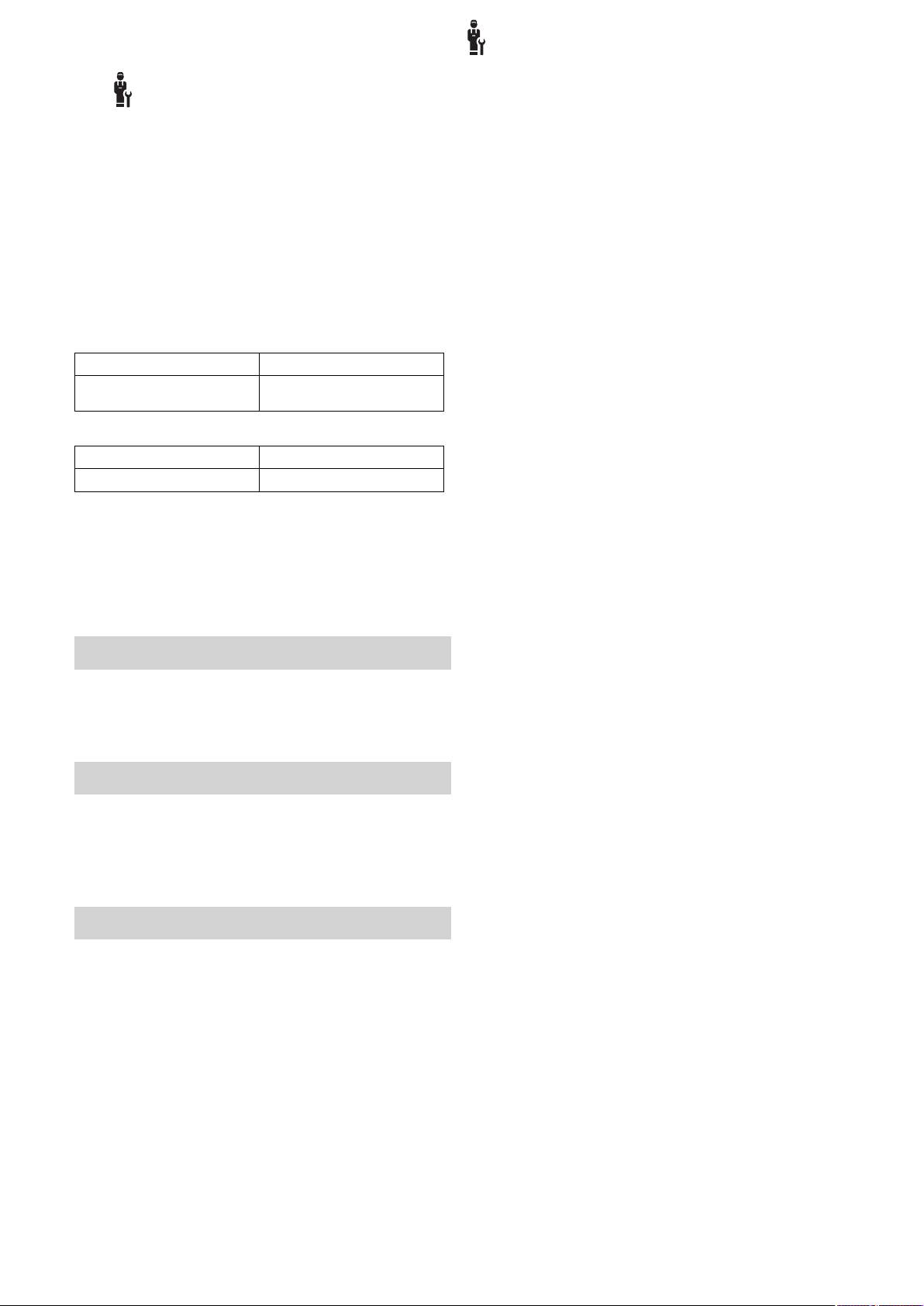
3 -- Instalación eléctrica, montaje
La instalación eléctrica debe ser realizada únicamente por
un especialista electricista.
La instalación de calefacción debe ponerse fuera de servicio
antes de realizar cualquier trabajo.
3.1 Selección de los cables
▶ No utilice cables flexibles para los cables de tensión de
red.
▶ Para los cables de tensión de red utilice cables con car-
casa (p. ej., NYM 3x1,5).
Sección de cable
Cable eBUS (baja tensión)
Cable de sonda (baja tensión)
Longitud de la línea
Cables de sonda
Cables de bus
≥ 0,75 mm²
≥ 0,75 mm²
≤ 50 m
≤ 125 m
-- Instalación eléctrica, montaje
3
3.2 Conexión del regulador del sistema al equipo de ventilación
1. Conecte el regulador del sistema a la unidad de ventila-
ción doméstica tal y como se describe en las instrucciones de instalación de la unidad de ventilación doméstica.
Condición: Equipo de ventilación conectado al eBUS sin VR 32, Equipo de
ventilación sin generador de calor eBUS
▶ Conecte el cable eBUS a los bornes eBUS del soporte
mural del regulador del sistema.
▶ Conecte el cable eBUS a los bornes eBUS del equipo
de ventilación.
Condición: Equipo de ventilación conectado al eBUS con VR 32, Equipo de
ventilación con hasta 2 generadores de calor eBUS
▶ Conecte el cable eBUS a los bornes eBUS del soporte
mural del regulador del sistema.
▶ Conecte el cable eBUS al eBUS del generador de calor.
▶ Ponga el conmutador de direcciones del VR 32 del dis-
positivo de ventilación en la posición 3.
Condición: Equipo de ventilación conectado al eBUS con VR 32, Equipo de
ventilación con más de 2 generadores de calor eBUS
▶ Conecte el cable eBUS a los bornes eBUS del soporte
mural del regulador del sistema.
▶ Conecte el cable eBUS al eBUS común de los genera-
dores de calor.
▶ Determine la posición más alta asignada en el conmuta-
dor de direcciones del VR 32 del generador de calor conectado.
▶ Sitúe el conmutador de direcciones del VR 32 del dispo-
sitivo de ventilación en la siguiente posición en sentido
ascendente.
0020287900_00 sensoCOMFORT Manual de uso e instalación 63

3
Ø6
VRC 720 VRC 693 VRC 9535
H05VVF
2 x 0,75 mm²
VRC 720
1,5 m
Ø6
60
1.
≤25 mm
A
B
C
2.
-- Instalación eléctrica, montaje
3.3 Montaje del regulador del sistema y sensor de temperatura exterior
64 Manual de uso e instalación sensoCOMFORT 0020287900_00

-- Instalación eléctrica, montaje
A
B
3.
VRC 693, VRC 9535
E
W
S
N
≥ 2,5 m
VRC 693
1.
Ø6
2.
3.
B
A
4.
B
A
3
0020287900_00 sensoCOMFORT Manual de uso e instalación 65
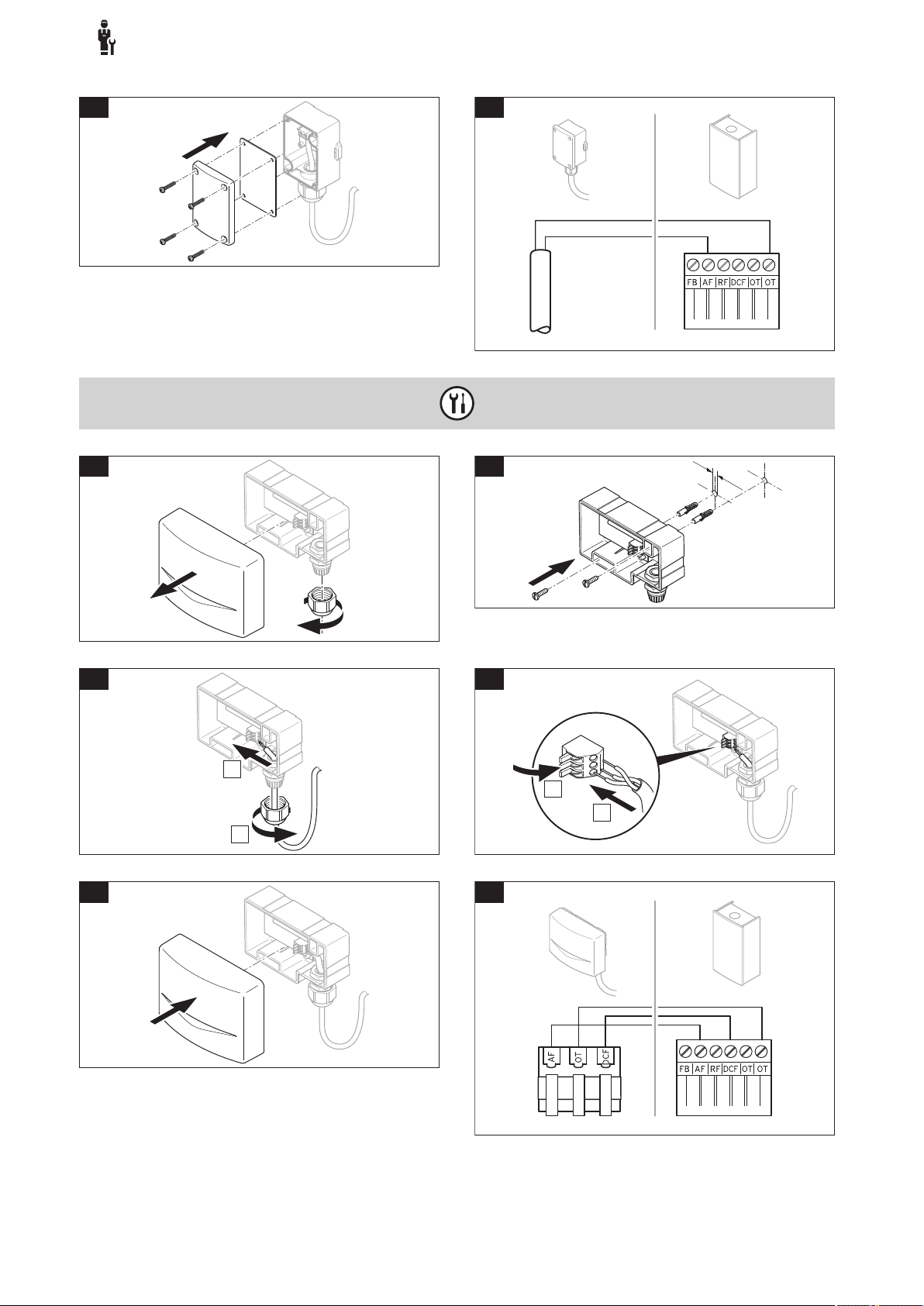
3
5.
6.
VRC 9535
D
C
F
O
T
AF
1.
Ø6
D
C
F
O
T
AF
2.
D
C
F
O
T
AF
3.
B
A
D
C
F
O
T
AF
4.
D
C
F
O
T
AF
B
A
D
C
F
O
T
AF
5.
6.
-- Instalación eléctrica, montaje
66 Manual de uso e instalación sensoCOMFORT 0020287900_00
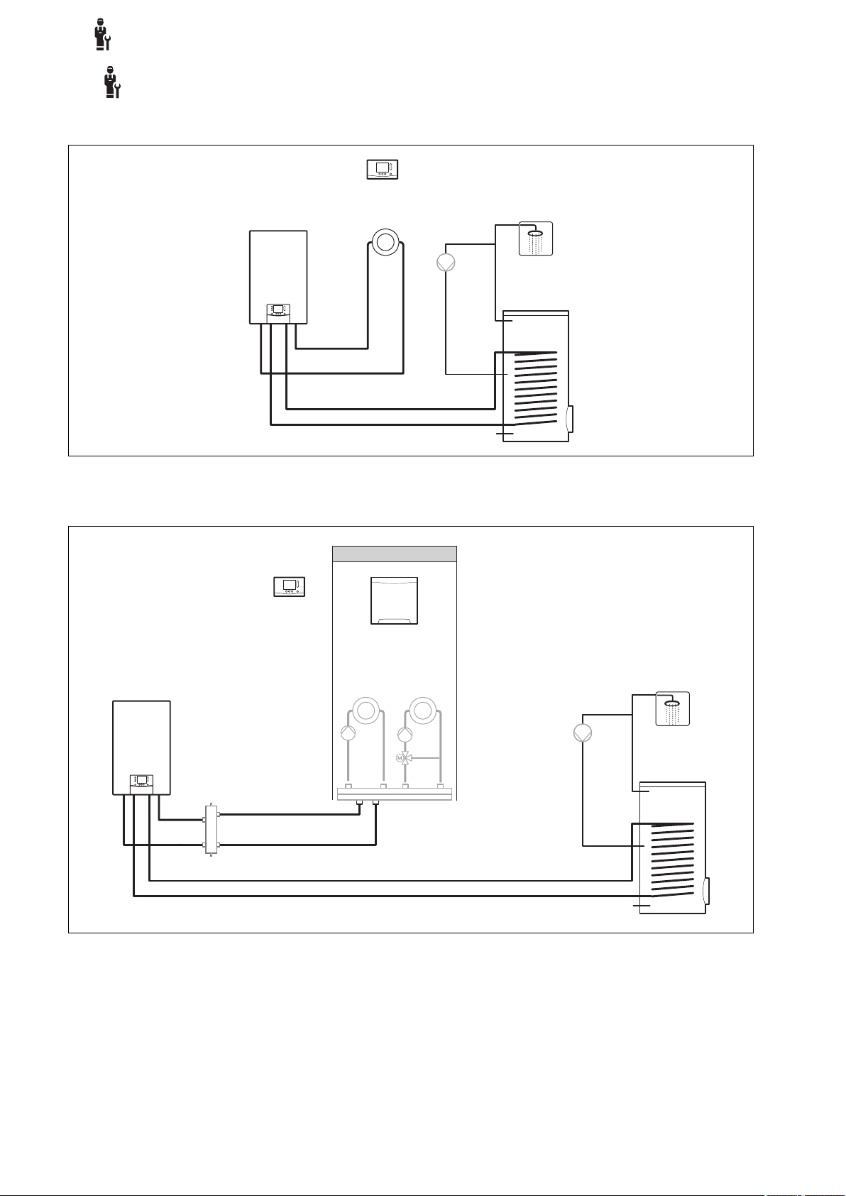
-- Uso de los módulos de función, esquema del sistema, puesta…
eBUS
VRC 720
VRC 720
eBUS
FM3 (VR 70)
4 -- Uso de los módulos de función, esquema del sistema, puesta en marcha
4.1 Sistema sin módulos de función
4
Los sistemas sencillos con un circuito de calefacción directo no necesitan ningún módulo de función.
4.2 Sistema con módulo de función FM3
Los sistemas con dos circuitos de calefacción que deben regularse por separado necesitan el módulo de función FM3.
El sistema no se puede ampliar con el mando a distancia VR 92.
0020287900_00 sensoCOMFORT Manual de uso e instalación 67

4
VRC 720
eBUS
VR 92
FM5 (VR 71)
FM3 (VR 70)
-- Uso de los módulos de función, esquema del sistema, puesta…
4.3 Sistema con módulos de función FM5 y FM3
Los sistemas con más de 2 circuitos de calefacción mixtos necesitan el módulo de función FM5.
El sistema puede incluir:
– máximo 1 módulo de función FM5
– máximo 3 módulos de función FM3, adicionales al módulo de función FM5
– máximo 4 mandos a distancia VR 92, que pueden incorporarse en cada circuito de calefacción
– máximo 9 circuitos de calefacción, que puede lograr con 1 módulo de función FM5 y 3 módulos de función FM3
4.4 Posibilidad de uso de los módulos de función
4.4.1 Módulo de función FM5
Cada configuración se corresponde con una asignación de conexión definida del módulo de función FM5 (→ Página 69).
Configuración
1 Soporte de calefacción solar y/o de agua caliente sanitaria con 2 acumuladores solares máx. 2
2 Soporte de calefacción solar y/o de agua caliente sanitaria con 1 acumulador solar máx. 3
3 3 circuitos de calefacción mezclados máx. 3
6 Acumulador multifunción allSTOR y estación de agua potable máx. 3
4.4.2 Módulo de función FM3
Con un módulo de función FM3 instalado, el sistema cuenta con un circuito de calefacción mixto y otro no mixto.
La posible configuración (FM3) se corresponde con una asignación de conexión definida del módulo de función FM3
(→ Página 70).
Propiedad del sistema Circuitos de
calefacción
mezclados
68 Manual de uso e instalación sensoCOMFORT 0020287900_00
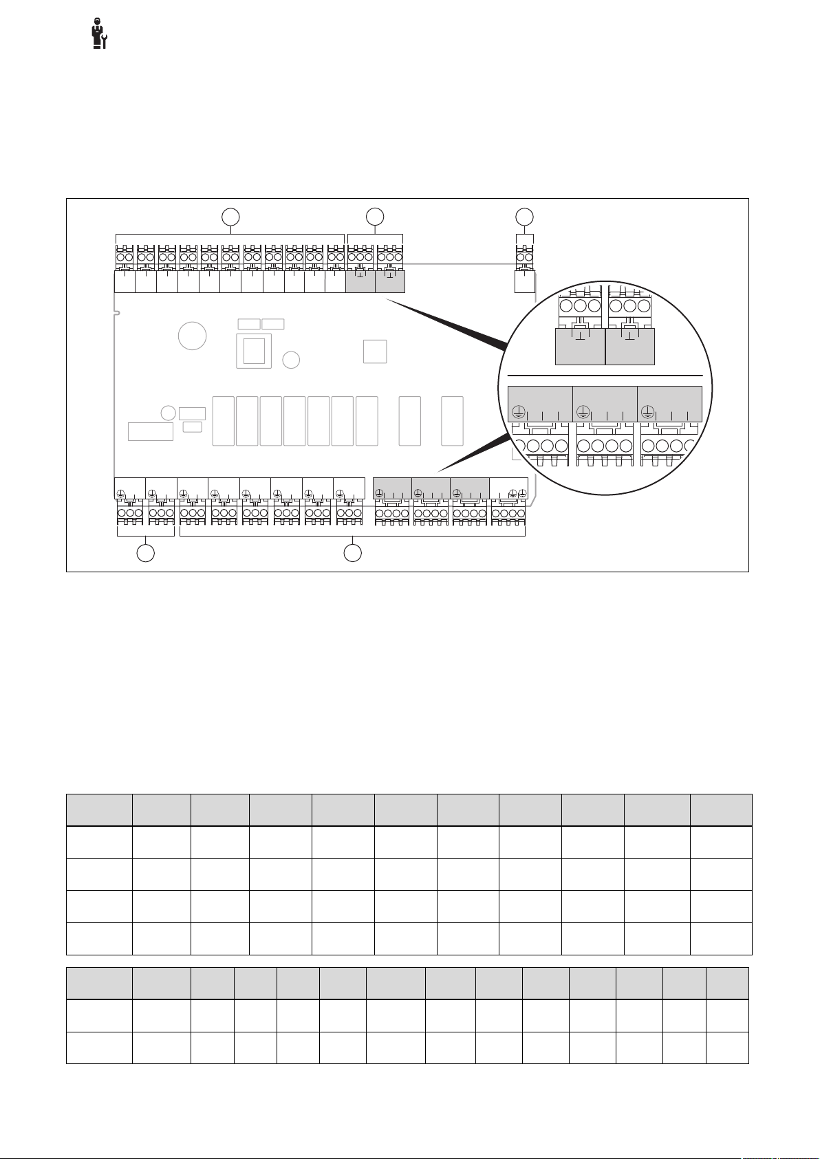
-- Uso de los módulos de función, esquema del sistema, puesta…
S112S212S312S412S512S612S712S812S912S1012S1112S12
OI
S13
OI
R7/8
N12
R13
NN
R11/12
N12
R9/10
N12
R6
L
N
R5
L
N
R4
L
N
R3
L
N
R2
L
N
R1
L
N
230V
L
N
230V
L
N
BUS
-+
4
5
1
2
3
R7/8
N12
R11/12
N12
R9/10
N12
S12
OI
S13
OI
4.4.3 Módulos de función FM3 y FM5
Si en un sistema están instalados los módulos de función FM3 y FM5, cada módulo adicional FM3 instalado amplía el sistema en dos circuitos de calefacción mixtos.
La posible configuración (FM3+FM5) se corresponde con una asignación de conexión definida del módulo de función FM3
(→ Página 70).
4.5 Asignación de conexión del módulo de función FM5
4
1 Terminales del sensor entrada
2 Terminales de señal
4 Terminales del relé salida
5 Conexión a la red
3 Borne eBUS
¡Prestar atención a la polaridad durante la conexión!
Terminales del sensor S6 hasta S11: conexión de un regulador externo también posible
Terminales de señal S12, S13: I = entrada, O = salida
Salida del mezclador R7/8, R9/10, R11/12: 1 = abierta, 2 = cerrada
Configure los contactos de las entradas externas en el regulador del sistema.
– Abierto,desc.: contactos abiertos, sin demanda de calor
– Puente, desc.: contactos cerrados, sin demanda de calor
Configuración
1 3f1 3f2 9gSolar MA 3j 3c/9e 9k1op/
2 3f1 3f2 3f3 MA 3j 3c/9e 9k1op/
3 3f1 3f2 3f3 MA – 3c/9e 9k1op/
6 3f1 3f2 3f3 MA 9gSolar 3c/9e 9k1op/
Configuración
1 SysFlow FS1 FS2 DHW
2 SysFlow FS1 FS2 FS3 DHW DHWBt COL Solar
R1 R2 R3 R4 R5 R6 R7/R8 R9/R10 R11/R12 R13
S1 S2 S3 S4 S5 S6 S7 S8 S9 S10 S11 S12 S13
DHW DHWBt COL Solar
Bt2
yield
yield
9k1cl
9k1cl
9k1cl
9k1cl
9k2op/
9k2cl
9k2op/
9k2cl
9k2op/
9k2cl
9k2op/
9k2cl
– –
9k3op/
9k3cl
9k3op/
9k3cl
9k3op/
9k3cl
DEM2 TD1 TD2 PWM –
– TD1 TD2 PWM –
–
–
–
0020287900_00 sensoCOMFORT Manual de uso e instalación 69
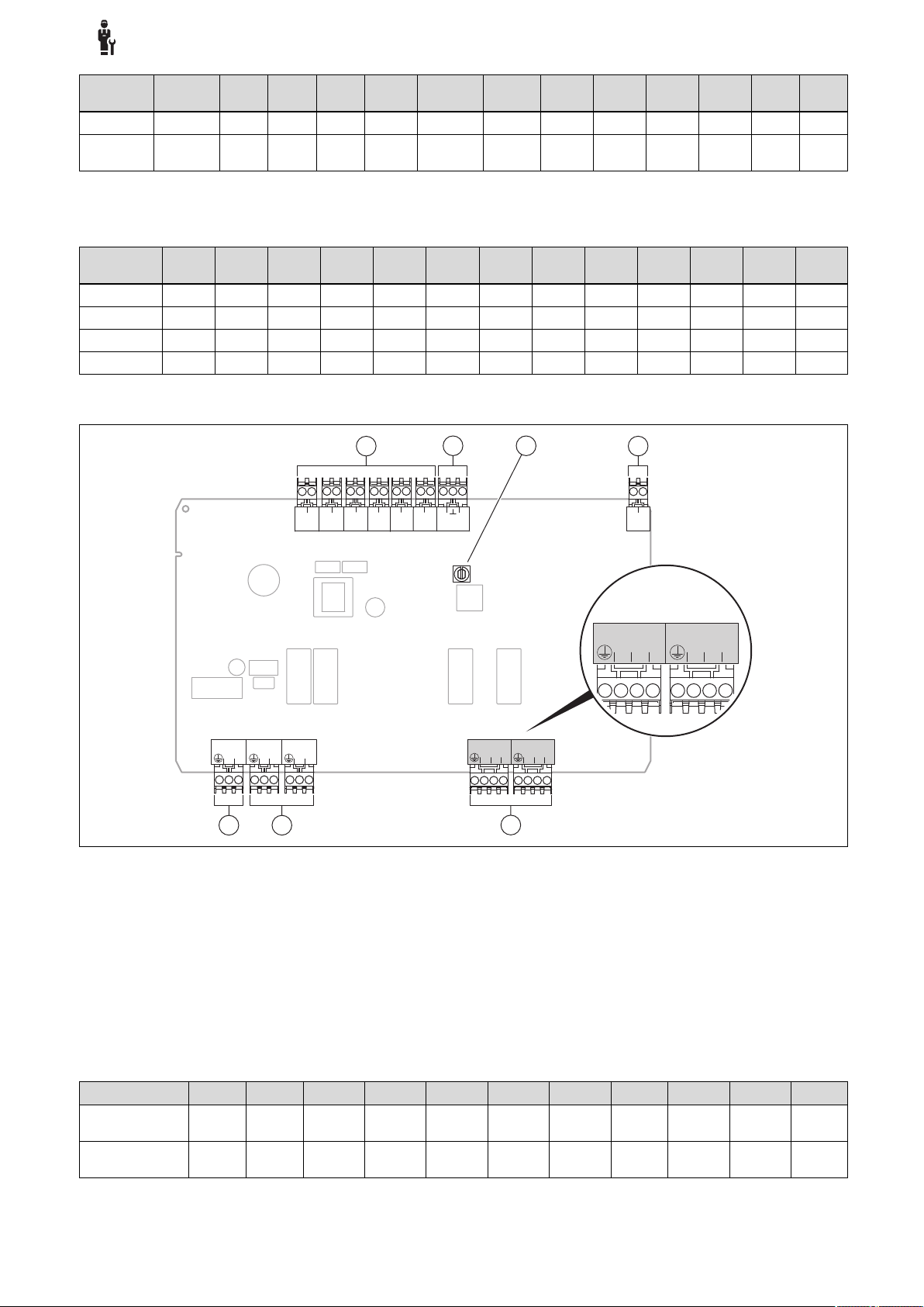
4
S112S212S312S412S512S612S7
OI
R3/4
N12
R5/6
N12
R2
L
N
R1
L
N
230V
L
N
BUS
-+
5
67
1
2
4
3
R3/4
N12
R5/6
N12
-- Uso de los módulos de función, esquema del sistema, puesta…
Configu-
S1 S2 S3 S4 S5 S6 S7 S8 S9 S10 S11 S12 S13
ración
3 SysFlow FS1 FS2 FS3 BufBt DEM1 DEM2 DEM3 DHW – – – –
6 SysFlow FS1 FS2 FS3 BufBt BufBtCH BufTop
DHW
BufBt
DHW
DEM1 DEM2 DEM3 – –
Significado de las abreviaturas (→ Página 74)
4.5.1 Asignación del sensor
Configuración
1 VR 10 VR 10 VR 10 VR 10 VR 10 VR 10 VR 11 VR 10 – VR 10 VR 10 – –
2 VR 10 VR 10 VR 10 VR 10 VR 10 VR 10 VR 11 VR 10 – VR 10 VR 10 – –
3 VR 10 VR 10 VR 10 VR 10 VR 10 – – – VR 10 VR 10 – – –
6 VR 10 VR 10 VR 10 VR 10 VR 10 VR 10 VR 10 VR 10 – – – VR 10 –
S1 S2 S3 S4 S5 S6 S7 S8 S9 S10 S11 S12 S13
4.6 Asignación de conexión del módulo de función FM3
1 Terminales del sensor entrada
2 Terminal de señal
3 Conmutador de direcciones
5 Salida del mezclador
6 Terminales del relé salida
7 Conexión a la red
4 Borne eBUS
Terminales del sensor S2, S3: conexión de un regulador externo también posible
Salida del mezclador R3/4, R5/6: 1 = abierta, 2 = cerrada
Configure los contactos de las entradas externas en el regulador del sistema.
– Abierto,desc.: contactos abiertos, sin demanda de calor
– Puente, desc.: contactos cerrados, sin demanda de calor
Configuración R1 R2 R3/R4 R5/R6 S1 S2 S3 S4 S5 S6 S7
FM3+FM5 3fa 3fb 9kaop/
9kacl
FM3 3f1 3f2 MA 9k2op/
Significado de las abreviaturas (→ Página 74)
9kbop/
9kbcl
9k2cl
– DEMa DEMb – FSa FSb –
BufBt/
DEM1 DEM2 – SysFlow FS2 –
DHW
70 Manual de uso e instalación sensoCOMFORT 0020287900_00
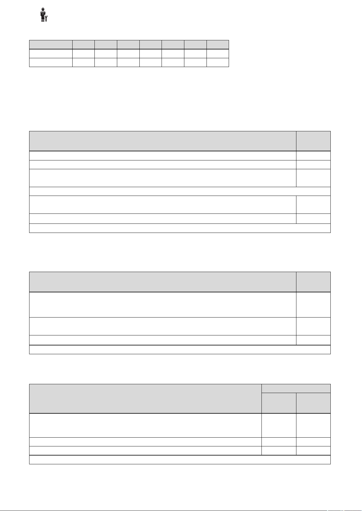
-- Uso de los módulos de función, esquema del sistema, puesta…
4.6.1 Asignación del sensor
Configuración S1 S2 S3 S4 S5 S6 S7
FM3+FM5 – – – – VR 10 VR 10 –
FM3 VR 10 – – – VR 10 VR 10 –
4.7 Ajustes del código del esquema del sistema
Los sistemas están agrupados aproximadamente según los componentes del sistema conectados. Cada agrupación recibe
un código del esquema del sistema que deberá introducir usted en el regulador del sistema en la función Código esquema
sistema:. El regulador del sistema necesita un código del esquema del sistema para liberar las funciones que dependen del
sistema.
4.7.1 Caldera de gas o aceite como aparato individual
4
Propiedad del sistema Código es-
allSTOR sistema acumulador incl. estación de agua potable 1
Calderas con soporte de agua caliente sanitaria solar 1
todas las calderas sin solar
– Conectar el sensor de temperatura del acumulador de agua caliente sanitaria a la caldera
Excepciones:
calderas sin solar
– Conectar el sensor de temperatura del acumulador de agua caliente sanitaria al módulo de función
Calderas con soporte de calefacción y de agua caliente sanitaria solar
1) No utilice la válvula de inversión prioritaria integrada de la caldera ecoTEC VC (posición permanente: modo calefacción).
quema sistema:
1
1)
2
1)
2
4.7.2 Cascada con calderas de gas o aceite
Máximo 7 calderas posibles
A partir de la segunda caldera, las calderas se conectan mediante VR 32 (dirección 2…7).
Propiedad del sistema Código es-
Producción de agua caliente sanitaria a través de una caldera seleccionada (circuito de aislamiento)
– Producción de agua caliente sanitaria a través de la caldera con la dirección más alta
– Conectar el sensor de temperatura del acumulador de agua caliente sanitaria a esta caldera
Producción de agua caliente sanitaria a través de toda la cascada (sin circuito de aislamiento)
– Conectar el sensor de temperatura del acumulador de agua caliente sanitaria al módulo de función FM5
allSTOR sistema acumulador incl. estación de agua potable
1) No utilice la válvula de inversión prioritaria integrada de la caldera ecoTEC VC (posición permanente: modo calefacción).
quema sistema:
1
1)
2
1)
2
4.7.3 Bomba de calor como aparato individual (monoenergética)
Con calentador de inmersión en la ida como caldera adicional
Propiedad del sistema Código esquema sistema:
sin intercambiador
de calor
sin solar
– Conectar el sensor de temperatura del acumulador de agua caliente sanitaria al módulo de regula-
ción de la bomba de calor o a la bomba de calor
con soporte de agua caliente sanitaria solar 8 11
allSTOR sistema acumulador incl. estación de agua potable 8 16
1) p. ej., VWZ MWT
0020287900_00 sensoCOMFORT Manual de uso e instalación 71
8 11
1)
con intercambiador
de calor
1)

4
-- Uso de los módulos de función, esquema del sistema, puesta…
4.7.4 Bomba de calor como aparato individual (híbrida)
Con caldera adicional externa
Una caldera adicional (con eBUS) se conecta mediante VR 32 (dirección 2).
Una caldera adicional (sin eBUS) se conecta en la salida de la bomba de calor o del módulo de regulación de la bomba de
calor para la caldera adicional externa.
Propiedad del sistema Código esquema sistema:
Producción de agua caliente sanitaria solo mediante caldera adicional sin módulo de función
– Conectar el sensor de temperatura del acumulador de agua caliente sanitaria a la caldera adicional
(regulación de carga propia)
Producción de agua caliente sanitaria solo mediante caldera adicional con módulo de función
– Conectar el sensor de temperatura del acumulador de agua caliente sanitaria a la caldera adicional
(regulación de carga propia)
Producción de agua caliente sanitaria mediante bomba de calor y caldera adicional
– Conectar el sensor de temperatura del acumulador de agua caliente sanitaria al módulo de función
FM5
– sin módulo de función FM5, conectar el sensor de temperatura del acumulador de agua caliente
sanitaria al módulo de regulación de la bomba de calor o a la bomba de calor
Producción de agua caliente sanitaria mediante bomba de calor y caldera adicional con acumulador de
agua caliente sanitaria bivalente
– conectar el sensor de temperatura del acumulador de agua caliente sanitaria superior a la caldera
adicional (regulación de carga propia)
– conectar el sensor de temperatura del acumulador de agua caliente sanitaria inferior al módulo de
regulación de la bomba de calor o a la bomba de calor
1) p. ej., VWZ MWT
sin intercambiador
de calor
8 10
9 10
16 16
12 13
1)
con intercambiador
de calor
1)
4.7.5 Cascada con bombas de calor
Máximo 7 bombas de calor posibles
Con caldera adicional externa
A partir de la segunda bomba de calor, las bombas de calor o los módulos de regulación de la bomba de calor se conectan
mediante VR 32 (B) (dirección 2…7).
Una caldera adicional (con eBUS) se conecta mediante VR 32 (siguiente dirección libre).
Una caldera adicional (sin eBUS) se conecta en la salida de la primera bomba de calor o del módulo de regulación de la
bomba de calor para la caldera adicional externa.
Propiedad del sistema Código esquema sistema:
Producción de agua caliente sanitaria solo mediante caldera adicional
– Conectar el sensor de temperatura del acumulador de agua caliente sanitaria a la caldera adicional
(regulación de carga propia)
Producción de agua caliente sanitaria mediante bomba de calor y caldera adicional
– Conectar el sensor de temperatura del acumulador de agua caliente sanitaria al módulo de función
FM5
1) p. ej., VWZ MWT
sin intercambiador
de calor
9 –
16 16
1)
con intercambiador
de calor
1)
72 Manual de uso e instalación sensoCOMFORT 0020287900_00

-- Uso de los módulos de función, esquema del sistema, puesta…
4.8 Combinaciones del esquema del sistema y configuración de los módulos de función
Con ayuda de la tabla, puede comprobar la combinación escogida del código del esquema del sistema y la configuración de
los módulos de función.
4
Có-
Sistema sin
digo esquema
sistema:
para generador de calor convencional
1 Caldera de gas/aceite x
Caldera de gas/aceite, cascada – – – – – –
2 Caldera de gas/aceite –
Caldera de gas/aceite, cascada – – – – – –
para sistemas de bomba de calor
8 sistema de bomba de calor
monoenergético
sistema híbrido x – – – – – – – –
9 sistema híbrido –
Cascada de bombas de calor – – – – – –
10 sistema de bomba de calor mo-
noenergético con intercambia-
dor de calor
Sistema híbrido con intercam-
biador de calor
2)
2)
11 sistema de bomba de calor mo-
noenergético con intercambia-
dor de calor
2)
12 sistema híbrido x
13 Sistema híbrido con intercam-
biador de calor
16 Sistema híbrido con intercam-
biador de calor
2)
2)
Cascada de bombas de calor – – – – – –
sistema de bomba de calor mo-
noenergético con intercambia-
dor de calor
2)
x: combinación posible
–: combinación no posible
1) gestión de inercia posible
2) p. ej., VWZ MWT
FM5,
sin
FM3
x
x
x
x
–
–
x
con
FM3
1)
x
1)
x
1)
x
1)
x
1)
x
1)
x
1)
x
1)
x
1)
x
1)
x
1)
x
con FM5 con
Configuración
1 2 1 2 3 6
Producción de
agua caliente
Calefacción de
apoyo solar
FM5
+
máx. 3
FM3
sanitaria solar
x x – –
– – x x
x x – –
– – – –
– – – –
– – – –
x x – –
– – – –
– – – –
– – – –
– – – –
1)
x
1)
x
1)
x
1)
x
1)
x
1)
x
1)
x
1)
x
1)
x
1)
x
1)
x
1)
x
1)
x
1)
x
1)
x
1)
x
– x
– x
1)
x
1)
x
– x
– x
– x
– x
– x
– x
– x
1)
x
1)
x
1)
x
x
x
x
x
x
x
0020287900_00 sensoCOMFORT Manual de uso e instalación 73

4
-- Uso de los módulos de función, esquema del sistema, puesta…
4.9 Esquema del sistema y esquema de conexiones
4.9.1 Significado de las abreviaturas
Abreviatura Significado
1 Generador de calor
1a Agua caliente sanitaria de la caldera adicio-
nal
1b Calefacción de la caldera adicional
1c Agua caliente sanitaria/calefacción de la
caldera adicional
1d Caldera de combustible sólido de carga
manual
2 Bomba de calor
2a Bomba de calor de aire-agua
2b Intercambiador de calor de aire-solución
salina
2c Unidad exterior de bomba de calor split
2d Unidad interior de bomba de calor split
2e Módulo de agua subterránea
2f Módulo para enfriamiento pasivo
3 Bomba de circulación generador de calor
3a Bomba de circulación piscina
3b Bomba del circuito de enfriamiento
3c Bomba carga ACS
3d Bomba de pozo
3e Bomba de recirculación
3f[x] Bomba de calefacción
3g Fuente de calor de la bomba de circulación
3h Bomba de protección contra la legionela
3i Bomba del intercambiador de calor
3j Bomba solar
4 Acumulador de inercia
5 Acumulador de agua caliente sanitaria mo-
novalente
5a Acumulador de agua caliente sanitaria biva-
lente
5b Acumulador con estratificación térmica
5c Acumulador combinado
5d Acumulador multifuncional
5e Torre hidráulica
6 Captador solar (térmico)
7a Estación de llenado de agua salina de la
bomba de calor
7b Estación solar
7c Estación de agua potable
7d Estación de habitación
7e Bloque hidráulico
7f Módulo hidráulico
7g Módulo de desacoplamiento de calor
7h Módulo del intercambiador de calor
7i Módulo de 2 zonas
7j Grupo de bomba
Abreviatura Significado
8a Válvula de seguridad
8b Válvula de seguridad agua potable
8c Grupo de seguridad de conexión de agua
potable
8d Grupo de seguridad del generador de calor
8e Membrana del vaso de expansión calefac-
ción
8f Membrana del vaso de expansión para agua
potable
8g Membrana del vaso de expansión
solar/solución salina
8h Recipiente previo del circuito solar
8i Fusible de flujo térmico
9a Válvula regulación de habitaciones (termos-
tática/motora)
9b Válvula de zona
9c Válvula de control de los ramales
9d Válvula de sobrepresión
9f Válvula de conmutación refrigeración
9e Válvula de conmutación de agua potable
9g Válvula de conmutación
9gSolar Válvula de conmutación solar
9h Llave de llenado y vaciado
9i Válvula de purga
9j Válvula de caperuza
9k[x] Válvula mezcladora de tres vías
9l Válvula mezcladora de tres vías refrigeración
9m Válvula mezcladora de tres vías con eleva-
ción del retorno
9n Mezclador termostático
9o Indicador volumétrico (Taco-Setter)
9p Válvula de cascada
10a Termómetro
10b Manómetro
10c Válvula antirretorno
10d Separador de aire
10e Colector de suciedad con separador de
magnetita
10f Recipiente colector solar/de solución salina
10g Intercambiador de calor
10h Compensador hidráulico
10i Conexiones flexibles
11a Convector fan-coil
11b Piscina
12 Regulador del sistema
12a Mando a distancia
12b Módulo de regulación de la bomba de calor
12c Módulo multifunción 2 de 7
12d Módulo de función FM3
12e Módulo de función FM5
12f Caja de cableado
12g Acoplador de bus eBUS
74 Manual de uso e instalación sensoCOMFORT 0020287900_00

-- Uso de los módulos de función, esquema del sistema, puesta…
4
Abreviatura Significado
12h Regulador solar
12i Regulador externo
12j Relé de desconexión
12k Termostato de máxima
12l Limitador de temperatura del acumulador
12m Sensor de temperatura exterior
12n Interruptor de caudal
12o Fuente de alimentación eBUS
12p Receptor por radio
12q Puerta de enlace a Internet
13 Unidad de ventilación doméstica
14a Salida del aire de entrada
14b Entrada del aire de salida
14c Filtro de aire
14d Reg. recalentamiento
14e Elemento de protección contra heladas
14f Silenciador
14g Válvula de mariposa
14h Rejilla de protección contra la intemperie
14i Caja de aire de salida
14j Humidificador de aire
14k Deshumidificador
14l Distribuidor de aire
14m Acumulador de aire
15 Unidad de ventilación del acumulador
BufBt Sensor de temperatura del acumulador de
inercia inferior
BufBtCH Sensor de temperatura parte de la calefac-
ción acumulador de inercia inferior
BufTopCH Sensor de temperatura parte de la calefac-
ción acumulador de inercia superior
BufBtDHW Sensor de temperatura parte ACS acumula-
dor de inercia inferior
BufTopDHW Sensor de temperatura parte ACS acumula-
dor de inercia superior
C1/C2 Activación de sobrealimentación/carga del
acumulador de inercia
COL Sonda del colector
DEM[x] Demanda de calor externa para el circuito de
calefacción
DHW Sensor de temperatura del acumulador
DHWBt Sensor de temperatura del acumulador infe-
rior (acumulador de agua caliente sanitaria)
DHWBt2 Sensor de temperatura del acumulador
(segundo acumulador solar)
EVU Contacto de conmutación de la empresa de
suministro de energía
FS[x] Sonda de temperatura de ida circuito de
calefacción/sensor de la piscina
MA Salida multifunción
ME Entrada multifunción
PV Interfaz del ondulador fotovoltaico
PWM Señal PWM para bomba
Abreviatura Significado
RT Termostato de ambiente
SCA Señal de refrigeración
SG Interfaz del gestor de la red de transmisión
Solar yield Cálculo ganancia solar
SysFlow Sensor de temperatura del sistema
TD1, TD2 Sensor de temperatura para una regulación
de la diferencia de temperatura
TEL Contacto de entrada del control remoto
TR Circuito de aislamiento con caldera conmuta-
ble
0020287900_00 sensoCOMFORT Manual de uso e instalación 75

4
-- Uso de los módulos de función, esquema del sistema, puesta…
4.9.2 Esquema del sistema 0020184677
4.9.2.1 Ajuste en el regulador del sistema
Código esquema sistema: 1
76 Manual de uso e instalación sensoCOMFORT 0020287900_00

-- Uso de los módulos de función, esquema del sistema, puesta…
4.9.2.2 Esquema del sistema 0020184677
4
0020287900_00 sensoCOMFORT Manual de uso e instalación 77
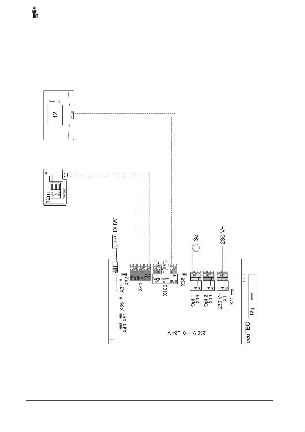
4
-- Uso de los módulos de función, esquema del sistema, puesta…
4.9.2.3 Esquema de conexiones 0020184677
78 Manual de uso e instalación sensoCOMFORT 0020287900_00

-- Uso de los módulos de función, esquema del sistema, puesta…
4.9.3 Esquema del sistema 0020284121
4.9.3.1 Ajustes en el regulador del sistema
Código esquema sistema: 1
Configuración FM3: 1
SM FM3: Bomba recirc.
Circuito 1 / Tipo de circuito: Calefacción
Circuito 1 / Control temp. amb.: Inactivo
Circuito 2 / Tipo de circuito: Calefacción
Circuito 2 / Control temp. amb.: Activo o Ampliado
Zona 1/ Zona activada: Sí
Zona 1 / Asignación de zona: Sin asig.
Zona 2/ Zona activada: Sí
Zona 2 / Asignación de zona: Regulador
4
0020287900_00 sensoCOMFORT Manual de uso e instalación 79
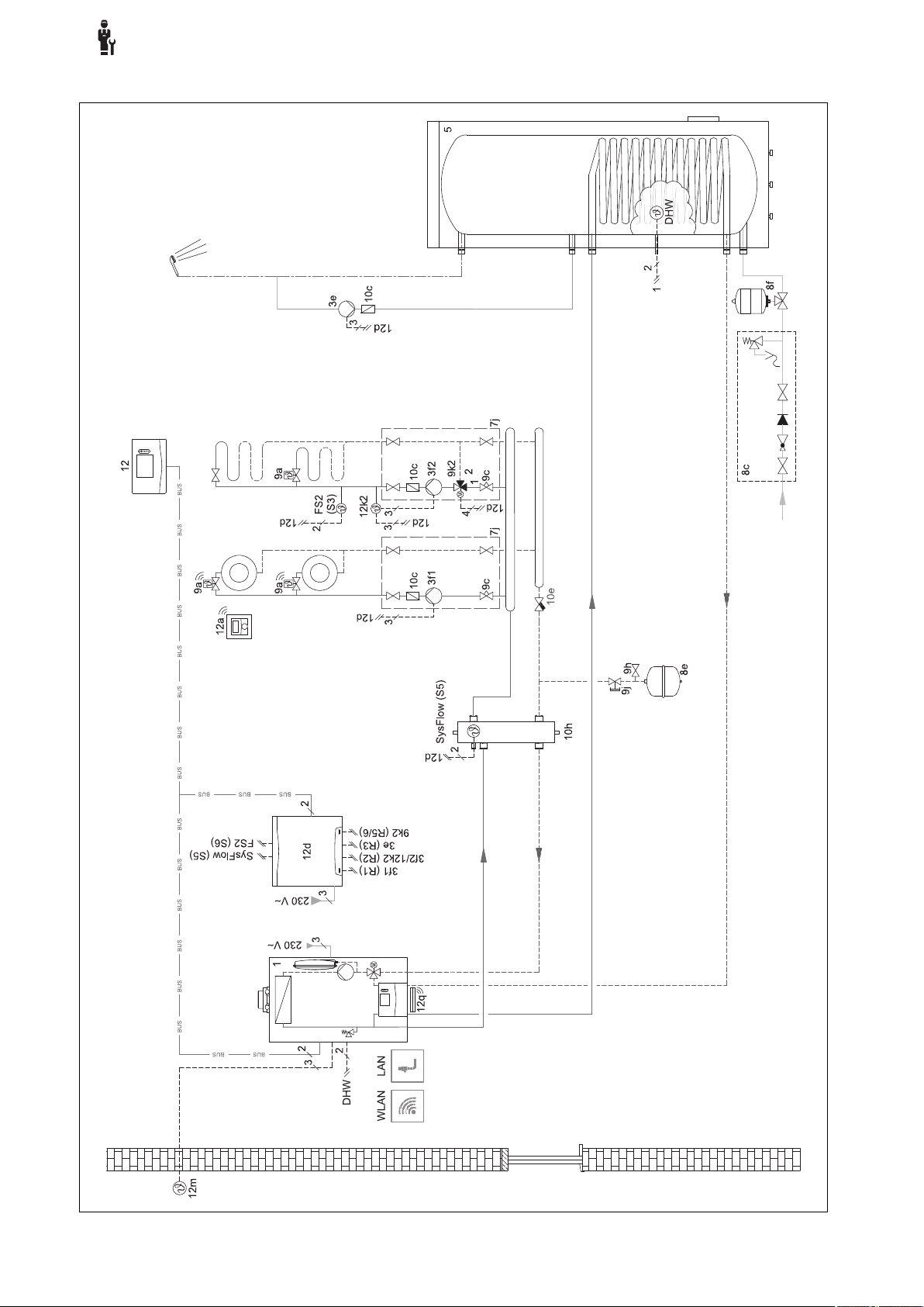
4
-- Uso de los módulos de función, esquema del sistema, puesta…
4.9.3.2 Esquema del sistema 0020284121
80 Manual de uso e instalación sensoCOMFORT 0020287900_00
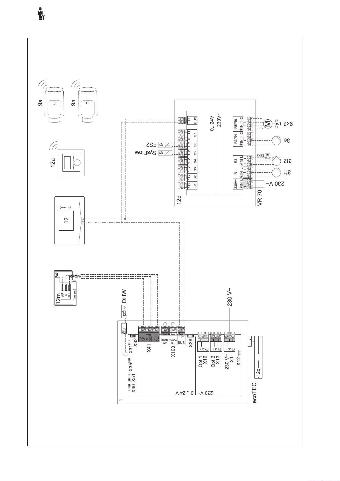
-- Uso de los módulos de función, esquema del sistema, puesta…
4.9.3.3 Esquema de conexiones 0020284121
4
0020287900_00 sensoCOMFORT Manual de uso e instalación 81

4
-- Uso de los módulos de función, esquema del sistema, puesta…
4.9.4 Esquema del sistema 0020177912
4.9.4.1 Particularidades del sistema
8: A través de una habitación de referencia sin válvula de regulación de temperatura de habitación individual debe po-
der fluir siempre al menos el 35 % del caudal nominal.
4.9.4.2 Ajustes en el regulador del sistema
Código esquema sistema: 8
Circuito 1 / Control temp. amb.: Activo o Ampliado
Zona 1 / Asignación de zona: Regulador
4.9.4.3 Ajustes en la bomba de calor
Tecnología de refrigeración: sin refrigeración
82 Manual de uso e instalación sensoCOMFORT 0020287900_00
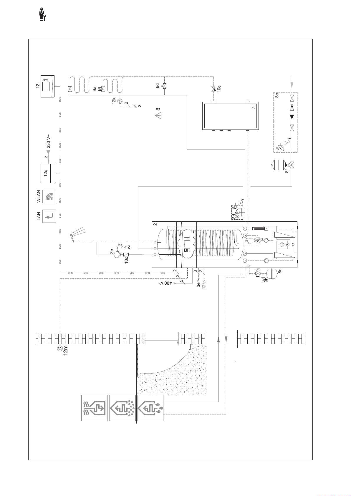
-- Uso de los módulos de función, esquema del sistema, puesta…
4.9.4.4 Esquema del sistema 0020177912
4
0020287900_00 sensoCOMFORT Manual de uso e instalación 83
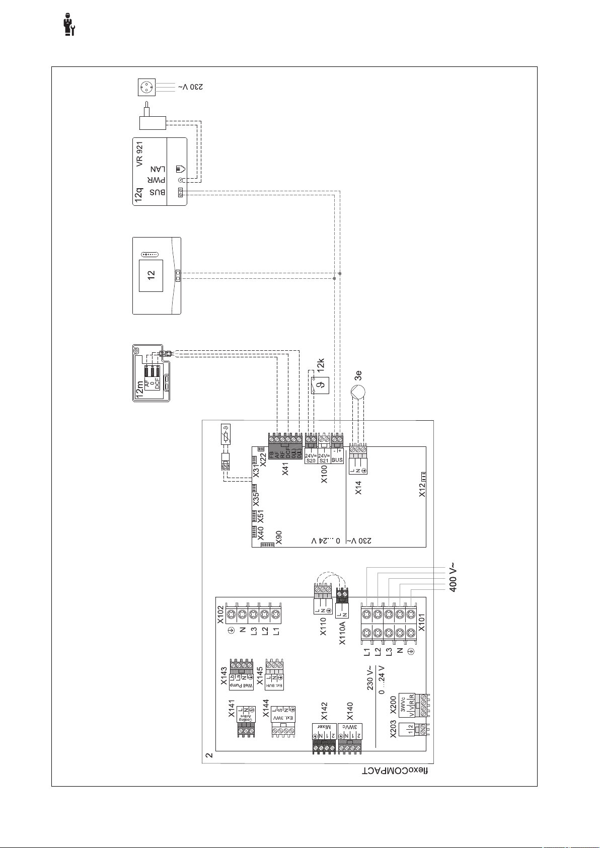
4
-- Uso de los módulos de función, esquema del sistema, puesta…
4.9.4.5 Esquema de conexiones 0020177912
84 Manual de uso e instalación sensoCOMFORT 0020287900_00

-- Uso de los módulos de función, esquema del sistema, puesta…
4.9.5 Esquema del sistema 0020280010
4.9.5.1 Particularidades del sistema
5: El limitador de temperatura del acumulador debe montarse en un lugar adecuado para evitar que la temperatura del
acumulador supere los 100 °C.
4.9.5.2 Ajustes en el regulador del sistema
Código esquema sistema: 1
Configuración FM5: 2
SM FM5: Bomba prot.legio.
Circuito 1 / Tipo de circuito: Calefacción
Circuito 1 / Control temp. amb.: Activo o Ampliado
Circuito 2 / Tipo de circuito: Calefacción
Circuito 2 / Control temp. amb.: Activo o Ampliado
Circuito 3 / Tipo de circuito: Calefacción
Circuito 3 / Control temp. amb.: Activo o Ampliado
Zona 1/ Zona activada: Sí
Zona 1 / Asignación de zona: Mando dist. 1
Zona 2/ Zona activada: Sí
Zona 2 / Asignación de zona: Mando dist. 2
Zona 3/ Zona activada: Sí
Zona 3 / Asignación de zona: Regulador
4
4.9.5.3 Ajustes en el mando a distancia
Dirección mando dist.: (1): 1
Dirección mando dist.: (2): 2
0020287900_00 sensoCOMFORT Manual de uso e instalación 85
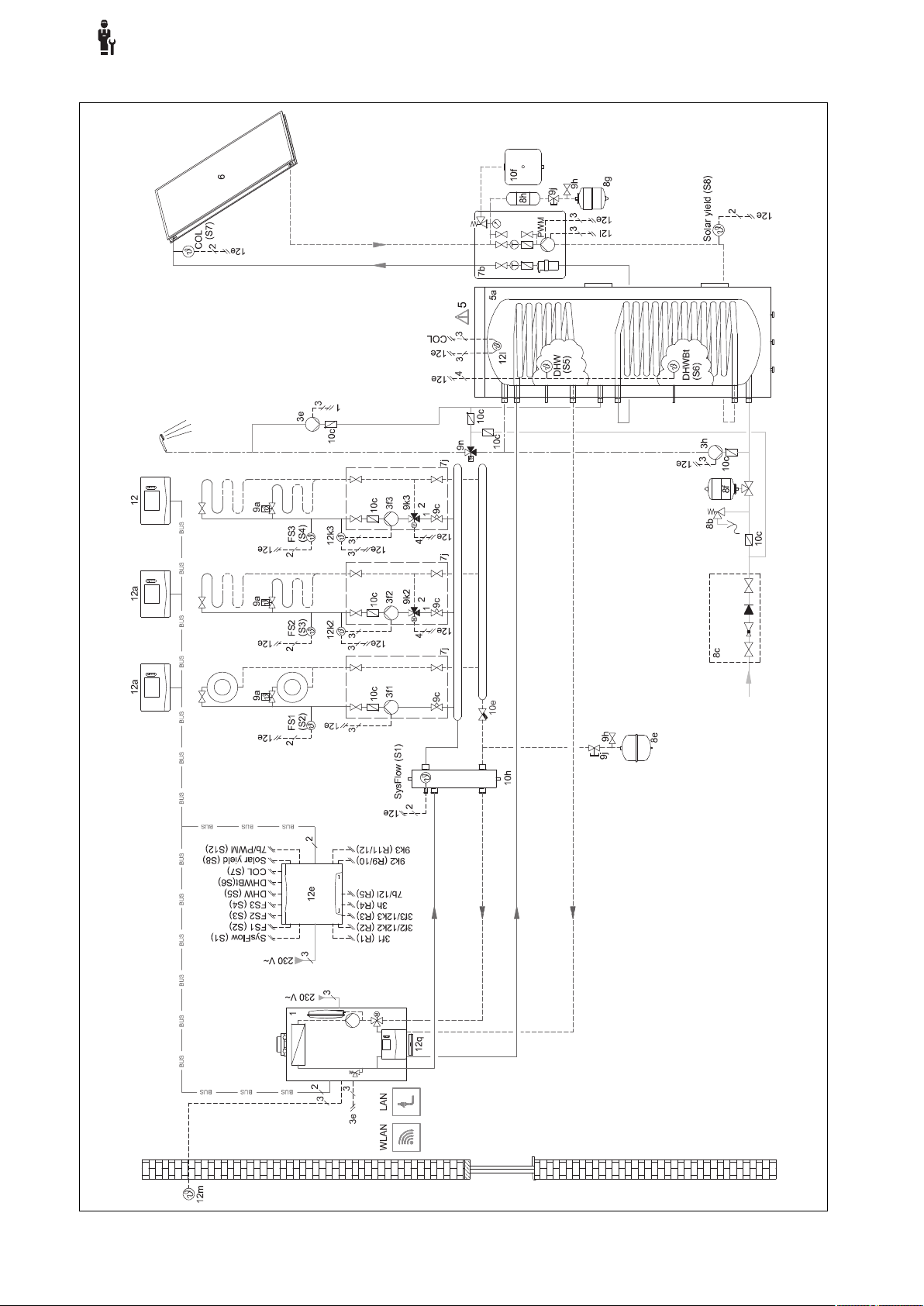
4
-- Uso de los módulos de función, esquema del sistema, puesta…
4.9.5.4 Esquema del sistema 0020280010
86 Manual de uso e instalación sensoCOMFORT 0020287900_00

-- Uso de los módulos de función, esquema del sistema, puesta…
4.9.5.5 Esquema de conexiones 0020280010
4
0020287900_00 sensoCOMFORT Manual de uso e instalación 87

4
-- Uso de los módulos de función, esquema del sistema, puesta…
4.9.6 Esquema del sistema 0020260774
4.9.6.1 Particularidades del sistema
17: Componente opcional
4.9.6.2 Ajuste en el regulador del sistema
Código esquema sistema: 1
Configuración FM5: 6
Circuito 1 / Tipo de circuito: Calefacción
Circuito 1 / Control temp. amb.: Activo o Ampliado
Circuito 2 / Tipo de circuito: Calefacción
Circuito 2 / Control temp. amb.: Activo o Ampliado
Circuito 3 / Tipo de circuito: Calefacción
Circuito 3 / Control temp. amb.: Activo o Ampliado
Zona 1/ Zona activada: Sí
Zona 1 / Asignación de zona: Mando dist. 1
Zona 2/ Zona activada: Sí
Zona 2 / Asignación de zona: Mando dist. 2
Zona 3/ Zona activada: Sí
Zona 3 / Asignación de zona: Regulador
4.9.6.3 Ajustes en el mando a distancia
Dirección mando dist.: (1): 1
Dirección mando dist.: (2): 2
88 Manual de uso e instalación sensoCOMFORT 0020287900_00

-- Uso de los módulos de función, esquema del sistema, puesta…
4.9.6.4 Esquema del sistema 0020260774
4
0020287900_00 sensoCOMFORT Manual de uso e instalación 89

4
-- Uso de los módulos de función, esquema del sistema, puesta…
4.9.6.5 Esquema de conexiones 0020260774
90 Manual de uso e instalación sensoCOMFORT 0020287900_00

5 -- Puesta en marcha
5.1 Requisitos para la puesta en marcha
– Ha finalizado el montaje y la instalación eléctrica del re-
gulador del sistema y del sensor de temperatura exterior.
–
El módulo de función FM5 está instalado y conectado
según la configuración 1, 2, 3 o 6, véase la hoja adjunta.
– Los módulos de función FM3 están instalados y conecta-
dos, véase la hoja adjunta. Cada módulo de función FM3
tiene asignada una dirección unívoca a través del conmutador de direcciones.
– Ha finalizado la puesta en marcha de todos los compo-
nentes del sistema (excepto regulador del sistema).
5.2 Ejecución del asistente de instalación
-- Puesta en marcha
Calefacción: la caldera adicional asume el modo calefac-
ción, la calefacción se calienta, el agua caliente sanitaria
está fría.
Agua caliente: la caldera adicional asume el modo de agua
caliente sanitaria, el agua caliente sanitaria se calienta, la
calefacción está fría.
ACS+Calent.: la caldera adicional asume el modo de calefacción y de agua caliente sanitaria, la calefacción y el agua
caliente sanitaria se calientan.
La caldera adicional no es tan eficiente como la bomba de
calor, por lo que el calor generado exclusivamente con la
caldera adicional es más caro.
Solución de averías (→ Anexo)
6.2 Mensaje de error
5
En el asistente de instalación se encuentran, bajo petición,
Idioma:.
El asistente de instalación del regulador del sistema le guía
a través de una lista de funciones. Seleccione para cada
función el valor de ajuste que se corresponda con la instalación de calefacción instalada.
5.2.1 Finalizar el asistente de instalación
Después de ejecutar el asistente de instalación, aparece en
la pantalla: Seleccione el siguiente paso.
Config. instalaciones: el asistente de instalación cambia a
la configuración de sistema del nivel de especialista, que le
permitirá continuar optimizando la instalación de calefacción.
Arranque instalación: el asistente de instalación cambia
a la pantalla básica y la instalación de calefacción funciona
con los valores ajustados.
Test sensores / actuadores: el asistente de instalación
cambia a la función comprobación de sonda/actuador. Aquí
puede probar los sensores y actores.
5.3 Modificación posterior de ajustes
En los niveles de uso de usuario o especialista podrá modificar posteriormente todos los ajustes que haya efectuado a
través de los asistentes de instalación.
En la pantalla aparece con el texto del mensaje de
error.
Puede encontrar los mensajes de error en: MENÚ → AJUS-
TES→ Nivel profesional autorizado → Historial de errores
Solución de problemas (→ Anexo)
6.3 Mensaje de mantenimiento
En la pantalla aparece con el texto del mensaje de mantenimiento.
Mensaje de mantenimiento (→ Anexo)
7 Información sobre el producto
7.1 Consulta y conservación de la documentación adicional
▶ Observe todas las instrucciones dirigidas a usted que
acompañan a los componentes de la instalación.
▶ Como usuario, conserve estas instrucciones y toda la
documentación adicional para su uso posterior.
7.2 Validez de las instrucciones
Estas instrucciones son válidas únicamente para:
6 Fallo, mensajes de error y
mantenimiento
6.1 Avería Comportamiento en caso de avería de la bomba de
calor
El regulador del sistema cambia al modo de emergencia, es
decir, la caldera adicional suministra energía calorífica a la
instalación de calefacción. El profesional autorizado ha disminuido la temperatura del modo de emergencia durante la
instalación. Notará que el agua caliente sanitaria y la calefacción no se calientan demasiado.
Hasta que el profesional autorizado llegue, puede seleccionar uno de los ajustes:
Descon.: la calefacción y el agua caliente sanitaria solo se
calientan de forma moderada.
0020287900_00 sensoCOMFORT Manual de uso e instalación 91
– 0020260921
7.3 Placa de características
La placa de características se encuentra en la parte posterior del producto.
Dato Significado
Número de serie para identificación, pos. 7ª a
16ª = referencia del aparato
sensoCOMFORT Denominación del aparato
V Tensión asignada
mA Corriente asignada
Leer las instrucciones

7 Información sobre el producto
7.4 Número de serie
Puede consultar el número de serie en MENÚ → INFORMA-
CIÓN→ Número de serie. La referencia del artículo de 10
dígitos se encuentra en la segunda línea.
7.5 Homologación CE
Con el distintivo CE se certifica que los productos cumplen
los requisitos básicos de las directivas aplicables conforme
figura en la declaración de conformidad.
Puede solicitar la declaración de conformidad al fabricante.
7.6 Garantía y servicio de atención al cliente
7.6.1 Garantía
En Country specifics encontrará información sobre la garantía del fabricante.
7.6.2 Servicio de Asistencia Técnica
Los datos de contacto de nuestro Servicio de Asistencia
Técnica se encuentran al dorso o en nuestro sitio web.
7.9 Datos técnicos - Regulador del sistema
Tensión asignada
Tensión de corriente asignada
Nivel de suciedad
Corriente asignada
Sección de cables de suministro
Tipo de protección
Clase de protección
Temperatura para la prueba de presión de
bola
Temperatura ambiente máxima permitida
humedad atmosférica actual
Modo de funcionamiento
Altura
Longitud
Profundidad
9 … 24 V
330 V
2
< 50 mA
0,75 … 1,5 mm²
IP 20
III
75 ℃
0 … 60 ℃
35 … 95 %
Tipo 1
109 mm
175 mm
26 mm
7.7 Reciclaje y eliminación
▶ Encargue la eliminación del embalaje al profesional auto-
rizado que ha llevado a cabo la instalación del producto.
Si el producto está identificado con este símbolo:
▶ En ese caso, no deseche el producto junto con los resi-
duos domésticos.
▶ En lugar de ello, hágalo llegar a un punto de recogida de
residuos de aparatos eléctricos o electrónicos usados.
----- Embalaje -----------------
▶ Elimine el embalaje de forma adecuada.
▶ Se deben tener en cuenta todas las especificaciones
relevantes.
7.8 Datos del producto según la ordenanza de la UE n.º 811/2013, 812/2013
A la eficiencia energética estacional para calefacción de los
aparatos que integran en la instalación un regulador controlado por sonda exterior y con la posibilidad de activar la función de termostato ambiente, se le suma siempre el factor
de corrección de la clase tecnológica VI para reguladores.
Es posible que se produzcan divergencias en la eficiencia
energética estacional de la calefacción si se desactiva esta
función.
Clase del regulador de temperatura
Contribución a la eficiencia energética
estacional de calefacción ɳs
VI
4,0 %
92 Manual de uso e instalación sensoCOMFORT 0020287900_00

Anexo
Anexo
A Solución de problemas, mensaje de mantenimiento
A.1 Solución de averías
Avería posible causa Medida
La pantalla está oscura Error de software 1. Pulse la tecla situada en la parte superior a la derecha sobre
No es posible efectuar cambios
en la pantalla mediante los paneles de mandos
Pantalla: Bloqueo de teclas
activado, no se pueden cambiar los ajustes ni los valores
Pantalla: Modo caldera adic.
con error Bomba calor (acceder cod. niv. esp.), calenta-
miento insuficiente de la calefacción y del agua caliente sanitaria
Pantalla: F. Error caldera, en
la pantalla aparece el código
concreto del error, p. ej., F.33
con la caldera concreta
Pantalla: No comprende el
idioma ajustado
Error de software 1. Pulse la tecla situada en la parte superior a la derecha sobre
Bloqueo de teclas activo ▶ Pulse la tecla situada en la parte superior a la derecha sobre
La bomba de calor no funciona 1. Informe al profesional autorizado.
Error en la caldera 1. Elimine las averías de la caldera seleccionando primero Res-
Idioma incorrecto ajustado 1.
el regulador del sistema durante más de 5 segundos para
forzar el reinicio.
2. Desconecte el interruptor de red de todos los generadores
de calor durante aprox. 1 minuto y vuelva a conectarlo.
3. Si el mensaje de error persiste, informe al profesional autorizado.
el regulador del sistema durante más de 5 segundos para
forzar el reinicio.
2. Desconecte el interruptor de red de todos los generadores
de calor durante aprox. 1 minuto y vuelva a conectarlo.
3. Si el mensaje de error persiste, informe al profesional autorizado.
el regulador del sistema durante aprox. 1 segundo para desactivar el bloqueo de teclas.
2. Seleccione el ajuste para el modo de emergencia hasta que
llegue el profesional autorizado.
3. Encontrará información más detallada en Fallo, mensajes de
error y mantenimiento (→ Página 91).
tablecer y, a continuación, Sí.
2. Si el mensaje de error persiste, informe al profesional autorizado.
Pulse 2 veces .
2.
Seleccione el último punto del menú ( AJUSTES) y con-
firme con .
3.
En AJUSTES, seleccione el segundo punto del menú y
confirme con .
4.
Seleccione el idioma que desee y confirme con .
A.2 Mensajes de mantenimiento
# Mensaje de
aviso
1 Falta de agua:
siga las indicaciones del gen.
de calor.
0020287900_00 sensoCOMFORT Manual de uso e instalación 93
Descripción Trabajo de mantenimiento Intervalo
La presión del agua en la instalación de calefacción es demasiado baja.
Consulte el llenado de agua en
las instrucciones de funcionamiento del generador de calor
correspondiente
Véanse las Instrucciones de
funcionamiento del generador
de calor
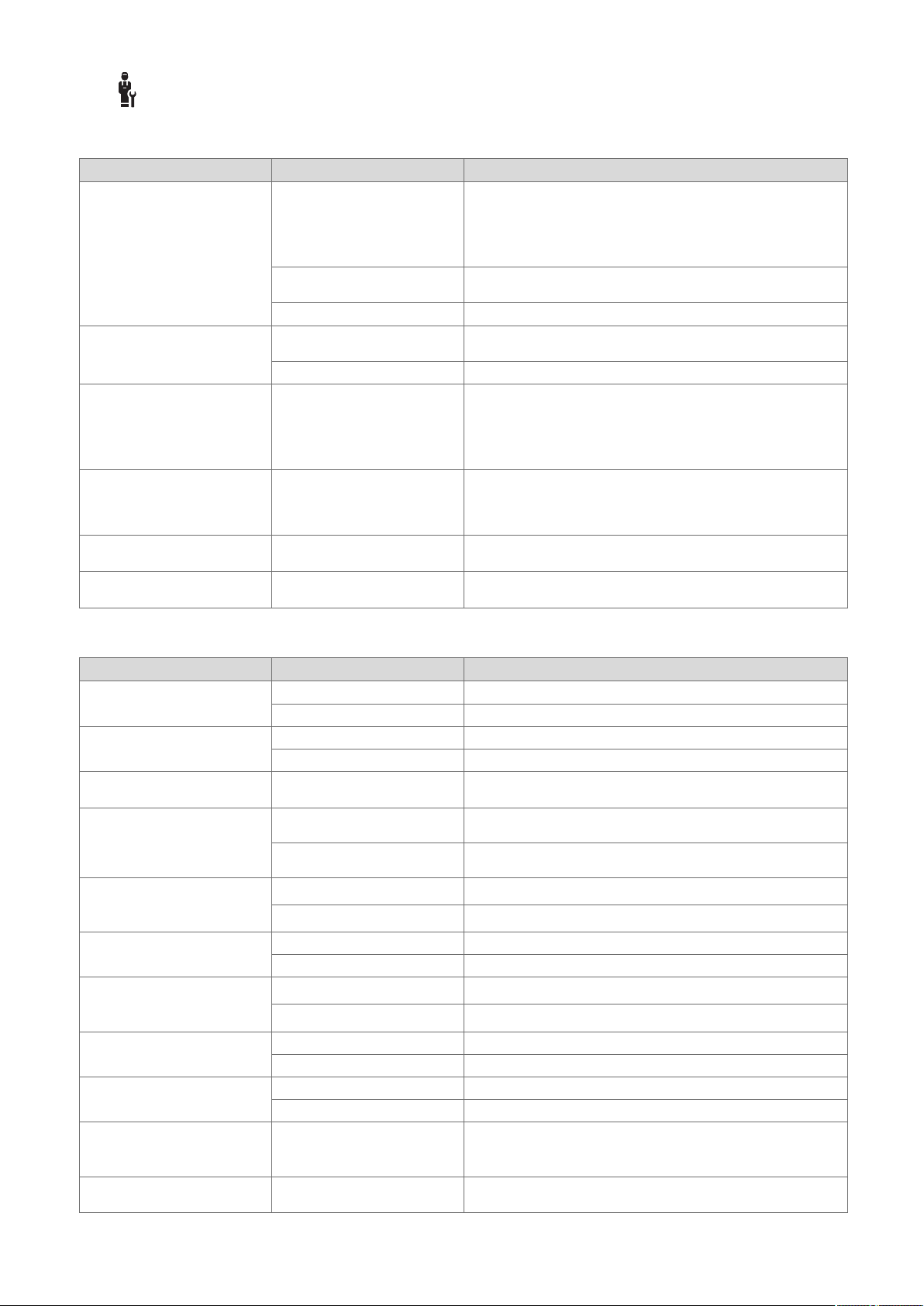
Anexo
B -- Solución de averías, solución de problemas, mensaje de mantenimiento
B.1 Solución de averías
Avería posible causa Medida
La pantalla está oscura Error de software 1. Pulse la tecla situada en la parte superior a la derecha sobre
Sin suministro de corriente en
el generador de calor
El producto está defectuoso ▶ Sustituya el producto.
No es posible efectuar cambios
en la pantalla mediante los paneles de mandos
El generador de calor continúa
calentando al alcanzar la temperatura ambiente
La instalación de calefacción
permanece en el funcionamiento de agua caliente sanitaria
Solo se muestra uno de varios
circuitos de calefacción
No se puede pasar al nivel de
especialista
Error de software ▶ Desconecte y vuelva a conectar el interruptor de red del gene-
El producto está defectuoso ▶ Sustituya el producto.
Valor incorrecto en la función
Control temp. amb.: o Asignación de zona:
El generador de calor no puede
alcanzar la temperatura de ida
nominal máxima
Circuito de calefacción inactivo ▶ Establezca en la función Tipo de circuito: el funcionamiento
Código para el nivel de profesional autorizado desconocido
el regulador del sistema durante más de 5 segundos para
forzar el reinicio.
2. Desconecte y vuelva a conectar el interruptor de red del generador de calor que alimenta al regulador del sistema.
▶ Establezca de nuevo el suministro eléctrico del generador de
calor que alimenta al regulador del sistema.
rador de calor que alimenta al regulador del sistema.
1. En la función Control temp. amb.:, ajuste el valor Activo o
Ampliado.
2. En la zona en la que está instalado el regulador del sistema,
asigne la dirección del regulador de sistema en la función
Asignación de zona:.
▶ En la función Temp. ida nominal máx.: °C, ajuste el valor
bajo.
deseado para el circuito de calefacción.
▶ Restablezca los ajustes de fábrica del regulador del sistema.
Todos los valores ajustados se pierden.
B.2 Eliminación del fallo
Mensaje de aviso posible causa Medida
Comunicación unid. ventilación
interrumpida
Comunicación módulo regul. BC
interrumpida
Señal sensor temp. ext. no válida
Comunicación generador calor1
interrumpida *,
* puede ser el generador de
calor 1 a 8
Comunicación FM3 dirección 1
interrumpida *,
* puede ser la dirección 1 a 3
Comunicación FM5 interrum-
pida
Comunicación mando dist. 1
interrumpida *,
* puede ser la dirección 1 a 3
Comunicación est. agua potable
interrumpida
Comunicación estación solar
interrumpida
Configuración FM3 [1]
incorrecta *,
* puede ser la dirección 1 a 3
Módulo ampl. ya no está sopor-
tado
Conexión rápida incorrecta ▶ Compruebe la conexión rápida.
Cable defectuoso ▶ Sustituya el cable.
Conexión rápida incorrecta ▶ Compruebe la conexión rápida.
Cable defectuoso ▶ Sustituya el cable.
Sensor de temperatura exterior
defectuoso
Cable defectuoso ▶ Sustituya el cable.
Conexión rápida incorrecta ▶ Compruebe la conexión rápida.
Cable defectuoso ▶ Sustituya el cable.
Conexión rápida incorrecta ▶ Compruebe la conexión rápida.
Cable defectuoso ▶ Sustituya el cable.
Conexión rápida incorrecta ▶ Compruebe la conexión rápida.
Cable defectuoso ▶ Sustituya el cable.
Conexión rápida incorrecta ▶ Compruebe la conexión rápida.
Cable defectuoso ▶ Sustituya el cable.
Conexión rápida incorrecta ▶ Compruebe la conexión rápida.
Cable defectuoso ▶ Sustituya el cable.
Conexión rápida incorrecta ▶ Compruebe la conexión rápida.
Valor de ajuste erróneo para el
FM3
Módulo conectado no adecuado ▶ Instale un módulo compatible con el regulador.
▶ Sustituya el sensor de temperatura exterior.
▶ Ajuste el valor de ajuste correcto para el FM3.
94 Manual de uso e instalación sensoCOMFORT 0020287900_00

Mensaje de aviso posible causa Medida
Módulo solar ya no está soportado
Mando a distancia ya no está
soportado
Código esquema del sistema
incorrecto
Falta mando a distancia 1 *,
* puede ser el mando a distan-
cia 1 o 2
Esquema sist. actual no soporta
FM5
Falta FM3 Falta FM3 ▶ Conecte el FM3.
Sensor temp. ACS S1 falta en
FM3
Bomba solar 1 notifica error *, *
bomba solar 1 o 2
Acum. estratif. térmica ya no
está soportado
Configuración SM2 mód. reg.
BC incorrecta
Configuración FM5 incorrecta Valor de ajuste erróneo para el
Cascada no soportada Se ha seleccionado un es-
Konfiguration FM3 [1] MA nicht
korrekt *, * puede ser la dirección 1 a 3
Configuración FM5 SM
incorrecta
Señal regulador sensor temp.
ambiente no válida
Señal sensor temp. ambiente
mando a distancia 1 no válida *,
* puede ser la dirección 1 a 3
Señal sensor S1 FM3 dirección
1 no válida *, * puede ser S1
hasta 7 y la dirección 1 a 3
Señal sensor S1 FM5 no válida
*, * puede ser S1 hasta S13
Generador de calor 1 notifica
error *, * puede ser el generador de calor 1 a 8
Unidad ventilación notifica error Avería del dispositivo de venti-
Módulo regulación BC notifica
error
Falta asignación mando a distancia 1 *, * puede ser la dirección 1 a 3
Falta activación de una zona Una zona empleada aún no
Módulo conectado no adecuado ▶ Instale un módulo compatible con el regulador.
Módulo conectado no adecuado ▶ Instale un módulo compatible con el regulador.
Código del esquema del sistema seleccionado incorrectamente
Falta el mando a distancia ▶ Conecte el mando a distancia.
FM5 conectado en la instalación de calefacción
Código del esquema del sistema seleccionado incorrectamente
Sensor de temperatura de agua
caliente sanitaria S1 no conectado
Avería en la bomba solar ▶ Compruebe la bomba solar.
Acumulador inadecuado conectado
FM3 conectado incorrectamente 1. Desmonte el FM3.
FM5 conectado incorrectamente 1. Desmonte el FM5.
▶ Ajuste el código del esquema del sistema correcto.
▶ Retire el FM5 de la instalación de calefacción.
▶ Ajuste el código del esquema del sistema correcto.
▶ Conecte el sensor de agua caliente sanitaria al FM3.
▶ Retire el acumulador de la instalación de calefacción.
2. Escoja una configuración adecuada.
2. Escoja otra configuración.
▶ Ajuste el valor de ajuste correcto para el FM5.
FM5
▶ Seleccione el esquema del sistema correcto que incluya cas-
quema del sistema incorrecto
Selección incorrecta del com-
ponente para la salida multifunción
Selección incorrecta del componente para la salida multifunción
Sonda de temperatura de ambiente defectuosa
Sonda de temperatura de ambiente defectuosa
Sensor averiado ▶ Sustituya la sonda.
Sensor averiado ▶ Sustituya la sonda.
Avería en el generador de calor ▶ Consulte las instrucciones del generador de calor indicado.
cadas.
▶ Seleccione el componente en la función SM FM3 que coincida
con el componente conectado en la salida multifunción FM3.
▶ Seleccione el componente en la función SM FM5 que coincida
con el componente conectado en la salida multifunción FM5.
▶ Sustituya el regulador.
▶ Sustituya el mando a distancia.
▶ Véanse las instrucciones de la unidad de ventilación domés-
lación
Avería del módulo de regula-
ción de la bomba de calor
Falta la asignación del mando a
distancia 1 con la zona.
tica.
▶ Sustituya el módulo de regulación de la bomba de calor.
▶ Asigne la dirección correcta al mando a distancia en la función
Asignación de zona:.
▶ En la función Zona activada:, seleccione el valor Sí.
está activada.
Circuito de calefacción inactivo ▶ Establezca en la función Tipo de circuito: el funcionamiento
deseado para el circuito de calefacción.
Anexo
0020287900_00 sensoCOMFORT Manual de uso e instalación 95
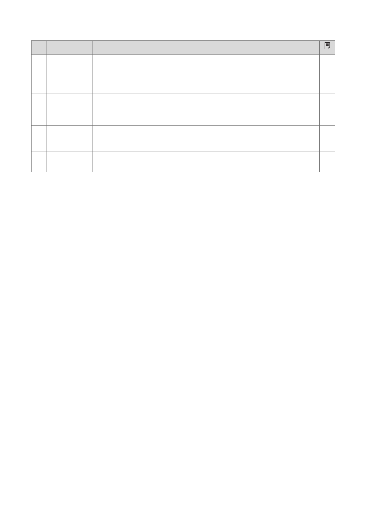
Anexo
B.3 Mensajes de mantenimiento
# Mensaje de
aviso
1 El generador de
calor 1 requiere
mantenimiento
*, * puede ser
el generador de
calor 1 a 8
2 La unidad de
ventilación requiere mantenimiento
3 Falta de agua:
siga las indicaciones del gen.
de calor.
4 Mantenimiento
Póngase en contacto con:
Descripción Trabajo de mantenimiento Intervalo
Para el generador de calor
existen trabajos de mantenimiento pendientes.
Para la unidad de ventilación
doméstica existen trabajos de
mantenimiento pendientes.
La presión del agua en la instalación de calefacción es demasiado baja.
Fecha en la que se debe realizar el mantenimiento de la instalación de calefacción.
Consulte los trabajos de mantenimiento en las instrucciones de
funcionamiento o de instalación
del generador de calor correspondiente
Consulte los trabajos de mantenimiento en las instrucciones
de funcionamiento o de instalación del dispositivo de ventilación correspondiente
Falta de agua: siga las instrucciones del generador de calor
Realice los trabajos de mantenimiento requeridos
Véanse las instrucciones de
funcionamiento o de instalación
del generador de calor
Véanse las instrucciones de
funcionamiento o de instalación
de la unidad de ventilación doméstica
Véanse las instrucciones de
funcionamiento o de instalación
del generador de calor
Fecha introducida en el regulador
96 Manual de uso e instalación sensoCOMFORT 0020287900_00

Índice de palabras clave
A
Averías ................................................................................91
C
Cables, longitud máxima .....................................................63
Cables, sección transversal mínima.................................... 63
Cables, selección ................................................................ 63
Conexión del regulador del sistema al equipo de
ventilación ...........................................................................63
Cualificación........................................................................50
Curva de calefacción, ajuste ............................................... 52
D
Disposiciones ......................................................................50
Documentación ................................................................... 91
E
Ejecución del asistente de instalación.................................91
Eliminación.......................................................................... 92
Error ....................................................................................91
Evitar un funcionamiento erróneo ....................................... 52
F
Funciones de mando e indicación....................................... 53
H
Heladas ...............................................................................50
Homologación CE ...............................................................92
M
Mantenimiento..................................................................... 91
N
Número de serie .................................................................. 92
Número de serie, lectura .....................................................92
P
Panel de mandos ................................................................52
Pantalla ...............................................................................52
profesional autorizado.........................................................50
R
Reciclaje..............................................................................92
Referencia del artículo ........................................................92
Referencia del artículo, lectura............................................ 92
Requisitos para la puesta en marcha de la instalación de
calefacción .......................................................................... 91
Requisitos, puesta en marcha.............................................91
U
Utilización adecuada ........................................................... 50
Índice de palabras clave
0020287900_00 sensoCOMFORT Manual de uso e instalación 97

Conteúdo
Instruções de uso e instalação
Conteúdo
1 Segurança .......................................................... 99
1.1 Utilização adequada............................................ 99
1.2 Advertências gerais de segurança ...................... 99
1.3 -- Segurança/disposições............................... 99
2 Descrição do produto...................................... 100
2.1 Que nomenclatura é utilizada?.......................... 100
2.2 O que faz a função de proteção
anticongelante? ................................................. 100
2.3 O que significam as seguintes
temperaturas?.................................................... 100
2.4 O que é uma zona? ........................................... 100
2.5 O que é a circulação?........................................ 100
2.6 O que é uma regulação do valor fixo?............... 100
2.7 O que significa intervalo? .................................. 100
2.8 O que faz o Hybrid-Manager? ........................... 100
2.9 Evitar anomalia.................................................. 101
2.10 Definir a curva de aquecimento......................... 101
2.11 Mostrador, elementos de comando e
símbolos ............................................................ 101
2.12 Funções de operação e de apresentação......... 102
3 -- Instalação elétrica, montagem .............. 112
3.1 Seleção dos cabos ............................................ 112
3.2 Ligar o regulador do sistema ao aparelho de
ventilação........................................................... 112
3.3 Montar o regulador do sistema e o sensor
exterior............................................................... 113
4 -- Utilização dos módulos funcionais,
esquema do sistema, colocação em
funcionamento................................................. 116
4.1 Sistema sem módulos adicionais ...................... 116
4.2 Sistema com módulo funcional FM3 ................. 116
4.3 Sistema com módulos funcionais FM5 e
FM3.................................................................... 117
4.4 Possibilidade de utilização dos módulos
funcionais........................................................... 117
4.5 Ocupação das ligações módulo funcional
FM5.................................................................... 118
4.6 Ocupação das ligações módulo funcional
FM3.................................................................... 119
4.7 Definições do código do esquema do
sistema .............................................................. 120
4.8 Combinações de esquema do sistema e
configuração de módulos funcionais ................. 122
4.9 Esquema do sistema e esquema de
conexões ........................................................... 123
5 -- Colocação em funcionamento............... 140
5.1 Requisitos para a colocação em
funcionamento ................................................... 140
5.2 Executar o assistente de instalação.................. 140
5.3 Alterar as definições posteriormente ................. 140
6 Falha, mensagens de erro e de
manutenção...................................................... 140
6.1 Falha.................................................................. 140
6.2 Mensagem de erro............................................. 140
6.3 Mensagem de manutenção ............................... 140
7 Informação sobre o produto........................... 141
7.1 Observar e guardar os documentos a serem
respeitados ........................................................ 141
7.2 Validade do manual ........................................... 141
7.3 Chapa de caraterísticas..................................... 141
7.4 Número de série ................................................ 141
7.5 Símbolo CE........................................................ 141
7.6 Garantia e serviço de apoio ao cliente .............. 141
7.7 Reciclagem e eliminação................................... 141
7.8 Dados do produto de acordo com o
regulamento UE N.º 811/2013, 812/2013.......... 141
7.9 Dados técnicos - Regulador do sistema............ 141
Anexo ...............................................................................142
A Eliminação de falhas, mensagem de
manutenção...................................................... 142
A.1 Eliminação de falhas.......................................... 142
A.2 Mensagens de manutenção .............................. 142
B -- Eliminação de falhas e de erros,
mensagem de manutenção ............................ 142
B.1 Eliminação de falhas.......................................... 142
B.2 Resolução de erros............................................ 143
B.3 Mensagens de manutenção .............................. 144
Índice remissivo .............................................................. 145
98 Instruções de uso e instalação sensoCOMFORT 0020287900_00
 Loading...