

Vaillant ecoMAX 646 Installation And Maintenance Manual
Installation and maintenance manual
ecoMAX
ecoMAX 646
For the installer
Wall hung room sealed fan assisted condensing boiler
GB

Installation and maintenance manual ecoMAX 646 / 0020020158_022
Contents
Notes on the documentation ...................................... 3
Other relevant documentation and service aids ..... 3
For the installer ..................................................................... 3
Symbols used .......................................................................... 3
1 Description of the appliance ........................... 4
1.1 Design .......................................................................... 4
1.2 Type summary ........................................................... 5
1.3 Data badge .................................................................. 5
1.4 CE marking.................................................................. 5
1.5 Intended use ............................................................... 5
2 Safety instructions and regulations .............. 6
2.1 Safety instructions ................................................... 6
2.1.1 Installing and setting the appliance ..................... 6
2.1.2 Smell of gas ................................................................ 6
2.1.3 Changes to the surroundings of the boiler ........ 6
2.1.4 Important instructions for propane appliances 6
2.2 General requirements .............................................. 6
2.2.1 Preliminary remarks for roomsealed appliances.. 6
2.2.2 Related documents ................................................... 6
3 Mounting ............................................................ 8
3.1 Scope of delivery and accessories ....................... 8
3.1.1 Unpack the boiler ...................................................... 8
3.2 Installation site .......................................................... 8
3.2.1 Select position of boiler .......................................... 8
3.2.2 Air supply .................................................................... 8
3.2.3 Compartment ventilation ........................................ 8
3.2.4 Electrical supply ........................................................ 8
3.3 Dimensional drawing and connections ................ 9
3.4 Required minimum gaps/assembly clearances ... 10
3.4.1 Using boiler template ............................................... 10
3.5 Mounting the appliance on the bracket .............. 10
3.6 Removing/Attaching the appliance casing ......... 10
4 Installation ......................................................... 11
4.1 Preparing the installation ....................................... 11
4.2 Technical instructions for the heating system .... 11
4.2.1 Direct connection to the heating circuit
using the integral boiler pump. ............................. 11
4.2.2 Connection to heating circuit containing
a low loss header. ..................................................... 11
4.3 Technical instructions for recharging ................. 12
4.4 Gas connection .......................................................... 12
4.5 Heating connections ................................................. 13
4.6.1 Flue termination ........................................................ 13
4.6.2 Flue pipe ...................................................................... 14
4.7 Condensate discharge ............................................. 14
4.8 Electrical connection ................................................ 15
4.8.1 Mains connection ...................................................... 15
4.8.2 Connecting controllers ............................................ 15
4.8.3 Connecting accessories and external
system components ................................................. 16
4.8.4 Connection diagram ................................................. 17
4.8.5 Wiring diagram .......................................................... 18
5 Initial start up and commissioning ................ 19
5.1 Water circulation system ........................................ 19
5.1.1 Treating the heating water..................................... 19
5.1.2 Heating side filling and bleeding ........................... 19
5.1.3 Final system flush (”Hot”) ...................................... 19
5.1.3 Hot water side filling and bleeding ....................... 20
5.1.4 Filling the siphon ....................................................... 20
5.2 Checking the gas setting ......................................... 20
5.2.1 Factory gas setting ................................................... 20
5.2.2 Gas inlet working pressure ..................................... 20
5.2.3 Checking the CO
2
content and adjusting
it if needed (air ratio setting) ................................ 21
5.3 Functional test ........................................................... 22
5.4 Instructing the user .................................................. 23
5.4.1 Instructing the user about the heating system . 23
5.4.2 Vaillant warranty....................................................... 23
6 Adapting the appliance to the heating system 24
6.1 Adjusting the central heating output
(range rating) ............................................................. 24
6.1.1 Setting the DHW part load output ........................ 24
6.2 Setting the pump over-run time ........................... 25
6.3 Setting the burner anti-cycling time .................... 25
7 Inspection and maintenance ........................... 26
7.1 Initial inspection ........................................................ 26
7.1.1 Safety instructions ................................................... 26
7.1.2 Maintenance ............................................................... 26
7.1.3 Overview of the inspection and maintenance
tasks ......................................................................................... 27
7.1.4 Functional check of boiler operation ................... 27
7.2 Servicing the compact thermal module .............. 27
7.2.1 Removing the compact thermal module ............. 27
7.2.2 Cleaning the heat exchanger ................................. 28
7.2.3 Checking the burner ................................................. 29
7.2.4 Cleaning the condensate siphon ........................... 29
7.2.5 Cleaning the condensate paths ............................. 29
7.3 Checking the gas setting ......................................... 29
7.4 Filling and venting the system ............................... 29
7.5 Draining the appliance and the system ............... 29
7.5.1 Draining the appliance ............................................. 29
7.5.2 Draining the entire system ..................................... 29
7.5.3 Cleaning the air separator ...................................... 29
7.6 Test operation............................................................ 29
8 Troubleshooting ................................................ 30
8.1 Diagnostics ................................................................. 30
8.1.1 Status codes ............................................................... 30
8.1.2 Diagnosis codes ......................................................... 31
8.1.3 Error codes ................................................................. 32
8.1.4 Error memory ............................................................ 32
8.1.5 Test programs ............................................................ 33
9 Vaillant Service ................................................. 34
10 Recycling and disposal ..................................... 34
10.1 Appliance ..................................................................... 34
10.2 Packaging .................................................................... 34
11 Technical data ................................................... 35
Benchmark gas boiler commissioning checklist .... 36
3Installation and maintenance manual ecoMAX 646 / 0020020158_02
Notes on the documentation
Notes on the documentation
The following information is intended to guide you
through the entire documentation.
Further documents apply in combination with this installation and maintenance manual.
We accept no liability for any damage caused by not
following these instructions.
Other relevant documentation and service aids
For the owner of the system
Brief operating instructions No. 00 20 00 64 61
Operating manual No. 00 20 01 46 08
For the installer
Installation Manual
Flue accessories No. 00 20 01 46 06
Checklist No. 00 20 02 01 60
Sticker with name of appliance No. 83 42 24
Installation template No. 12 41 82
Safety sticker No. 83 55 93
Service aids:
The following test and measuring equipment is required
for inspection and maintenance:
– Flue gas analyser
– Manometer (U gauge)
Attachment and storage of the documents
Please pass on this installation and maintenance manual
as well as the aids to the owner of the system, whose responsibility it is to ensure that the manuals and auxiliary
equipment are available whenever required.
Symbols used
Please observe the safety instructions in this installation
manual when installing the appliance!
Danger!
Immediate risk of serious injury or death!
Caution!
Potentially dangerous situations for product
and environment!
Note!
Useful information and instructions.
• Symbol for a necessary task
Installation and maintenance manual ecoMAX 646 / 0020020158_024
1 Description of the appliance
1 Description of the appliance
1.1 Design
1
2
3
4
7
8
9
10
11
5
6
14
13
12
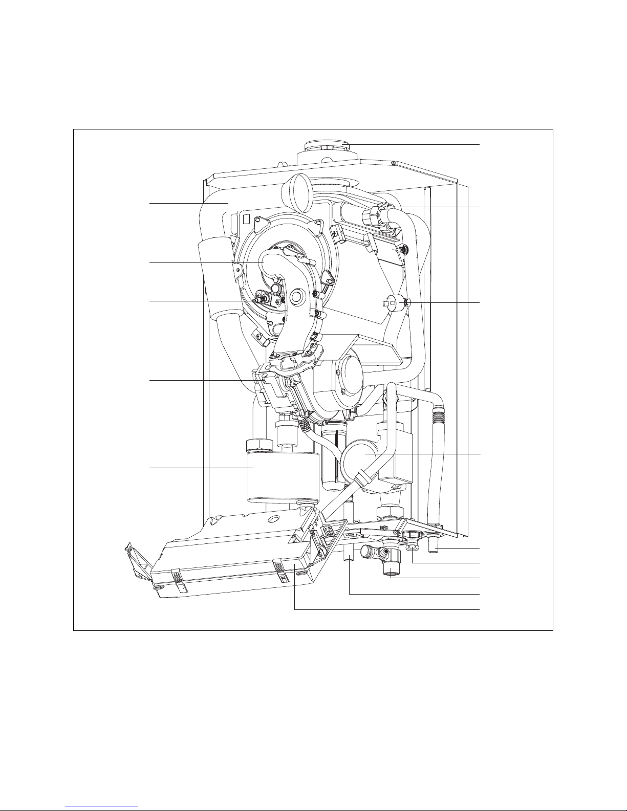
Fig. 1.1 Function elements
1 Connection for the flue pipe
2 Heat exchanger
3 Pressure switch
4 Pump
5 Electronics box
6 Return connection (with drain point)
7 Air separator
8 Electronic gas valve
9 Ignition electrode
10 Burner gas/air mixing chamber
11 Air intake pipe
12 Gas inlet
13 Connection for pressure relief valve
14 Connection for condensate discharge
5Installation and maintenance manual ecoMAX 646 / 0020020158_02
Description of the appliance 1
1.2 Type summary
Appliance
type
Country of destination
(designations
according to ISO 3166)
License
category
Type of gas Nominal heat output
range P (kW)
DHW primary
output (kW)
ecoMAX 646 GB (Great Britain)
I E (Eire)
II
2H3P
Natural gas H - G 20 -20 mbar
(Propane - G 31 - 37 mbar)
13.3 - 47.7 (40/30 °C)
12.3 - 44.1 (80/60 °C)
44.1
Table 1.1 Type summary
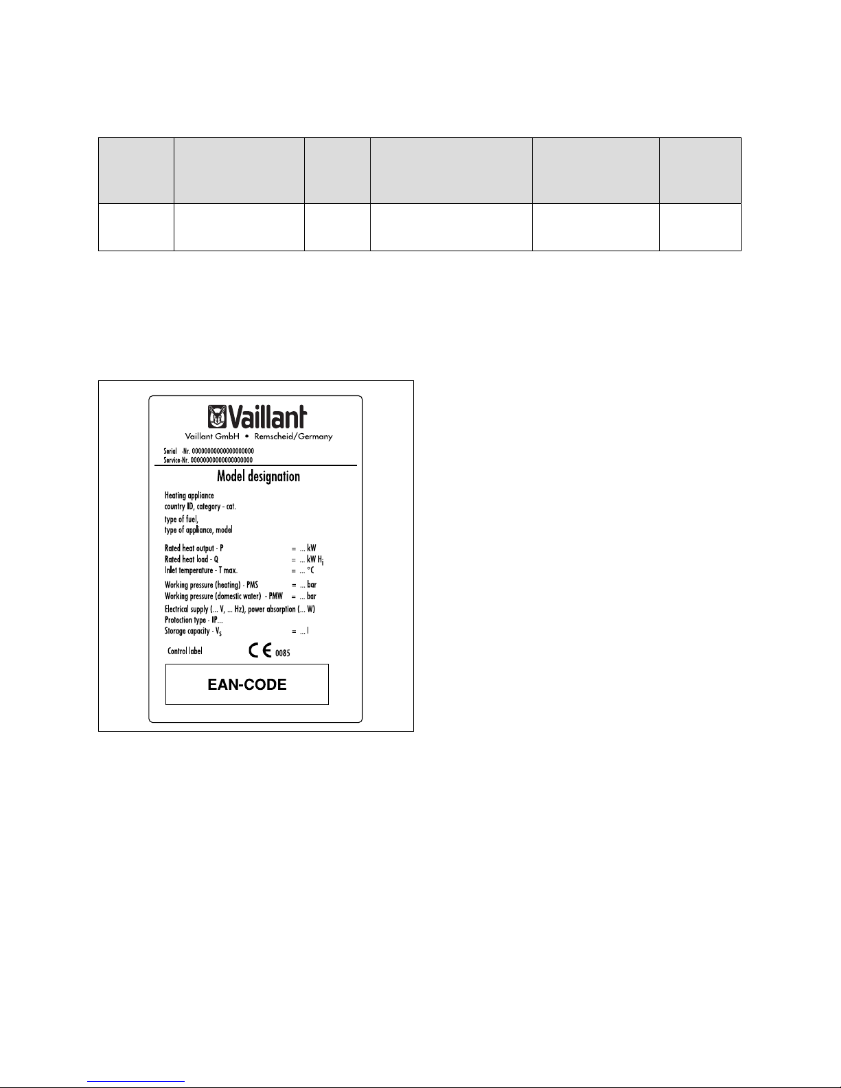
1.3 Data badge
The data badge of the Valliant ecoMAX 646 is attached
at the factory to the bottom of the appliance.
Fig. 1.2 Data badge (example)
1.4 CE marking
CE marking is used to document the fact that the appliances, in accordance with the type summary, meet the
basic requirements of the directive on appliances burning gaseous fuels (Council Directive 90/396/EEC) and
the EC directive on electromagnetic compatibility
(Council Directive 89/336/EEC). The appliances meet
the basic requirements of the efficiency requirements
directive (Council Directive 92/42/EEC).
The appliances meet the basic requirements of the efficiency requirements directive (Council Directive 92/42/
EEC) as condensing appliances.
1.5 Intended use
The Vaillant ecoMAX 646 is a state-of-the-art appliance
which has been constructed in accordance with recognised technical safety regulations. Nevertheless, danger
to the life and limb of the user or third parties can still
occur or the appliance or other material assets be damaged when using it.
The appliance is designed to be used as a heater for
closed hot water central heating systems. Any other use
or extended use is considered to be improper. The manufacturer or supplier is not liable for any damage resulting from improper use. The user alone bears the risk.
Appropriate use includes the observance of the operating and installation manual and the adherence to the inspection and maintenance conditions.
Installation and maintenance manual ecoMAX 646 / 0020020158_026
2 Safety instructions
2 Safety instructions and regulations
2.1 Safety instructions
2.1.1 Installing and setting the appliance
Important!
The appliance must be installed and serviced by
a competent person as stated in the Gas Safety
(Installation and Use) Regulations 1998. In IE,
the installation must be in accordance with the
current edition of IS 813 ‚Domestic Gas Installations‘, the current Building Regulations and
reference should be made to the current ETCI
rules for electrical installation.
2.1.2 Smell of gas
If you smell gas, the following safety instructions should
be observed:
• don‘t switch on any electrical switch in the danger area,
• don‘t smoke in the danger area,
• don‘t use a telephone in the danger area,
• close the gas stop cock,
• ventilate the danger area,
• contact your gas supplier or National Grid Transco
0800 111999.
2.1.3 Changes to the surroundings of the boiler
No changes must be made to the following devices:
– the boiler
– the gas, air, water and electricity supply pipes
– the flue pipe
– the discharge pipe and the safety valve for the hot water
– the constructional conditions that could affect the
operational reliability of the device.
2.1.4 Important instructions for propane appliances
Should the appliance be connected to an LPG supply,
ensure that the tank has been correctly filled and purged
prior to installation to the emergency gas control valve.
Danger!
Only propane G31 may be used.
Important!
When tightening or slackening screwed connections always use suitable open-ended spanners
(not pipe wrenches or extensions etc.). Incorrect use and/or unsuitable tools can lead to
damage being caused (e.g. gas or water leakage)!
2.2 General requirements
2.2.1 Preliminary remarks for roomsealed appliances
This appliance should only be installed in conjunction
with either a Vaillant flue system or an alternative approved system (details of flue approval categories can be
found in the technical section of the installation manual).
Install the flue system as detailed in the separate flue
installation instructions supplied with this boiler.
2.2.2 Related documents
The installation of the boiler must be in accordance with
the relevant requirements of Gas Safety (Installation
and Use) Regulations 1998, Health and Safety Document
No. 635 (The Electricity at Work Regulations 1989),
BS7671 (IEE Wiring Regulations) and the Water Supply
(Water Fitting) Regulations 1999, or The Water Bylaws
2000 (Scotland). It should also be in accordance with
the relevant requirements of the Local Authority, Building Regulations, The Building Regulations (Scotland).
The Building Regulations (Northern Ireland) and the
relevant recommendations of the following British
Standards:
BS 6700: Services supplying water for domestic use
within buildings and their curtilages.
BS 6798: Specification for installation of gas fired boil-
ers not exceeding 60 kW input.
BS 6891: Specification for installation of low pressure
gas pipework up to 28 mm (R1) in domestic
premises (2nd family gas).
BS 7593: Treatment of water in domestic hot water cen-
tral heating systems. Institute of Gas Engineers
Publication “IGE/UP/7 Edition 2 Gas installation
in timber framed and light steel framed buildings”
BS. 5482 Pt. 1 Domestic butane and propane gas burn-
ing installations.
IGE/UP1 Soundness testing and purging of industrial
and commercial gas installation.
IGE/UP2 Gas installation pipework, boosters and com-
pressors on industrial and commercial premises.
IGE/UP10 Installation of gas appliances in industrial and
commercial premises.
BS. 6644 Installation of gas fired hot water boilers of
rated inputs between 60 kW and 2 MW (2nd
and 3rd family gases).
BS. 5449 Forced circulation hot water central heating
systems for domestic premises.
Note: only up to 45 kW.
BS. 6880 Low temperature hot water heating systems
of output greater than 45 kW.
Part 1 Fundamental and design considerations.
Part 2 Selection of equipment.
Part 3 Installation, commissioning and maintenance.
BS. 4814 Specification for: Expansion vessels using
an internal diaphragm, for sealed hot water
heating systems.
BS. 5440 Installation and maintenance of flues and
ventilation for gas appliances of rated input
not exceeding 70 kW net (1st, 2nd and 3rd
family gases).
Part 1 Specification for installation of flues.
Part 2 Specification for installation and maintenance of ventilation for gas appliances.
7Installation and maintenance manual ecoMAX 646 / 0020020158_02
Important!
When tightening or loosening screwed connections
always use suitable open-ended spanners (not
pipe wrenches or extensions etc.). Incorrect use
and/or unsuitable tools can lead to damage being
caused (e.g. gas or water leakage)! Preliminary
remarks: This appliance should only be installed
in conjunction with a Vaillant flue system. Install
the flue system as detailed in the separate flue
installation instructions supplied with this boiler.
Boiler location
The location chosen for the boiler must permit the provision of a satisfactory flue termination. The location
must also provide adequate space for servicing and air
circulation around the boiler. The boiler may be installed
in any room, although particular attention is drawn to
the requirements of BS7671 (IEE Regulations), the electrical provisions of the Building Regulations (Scotland)
and in IE the current edition of IS 813 and the current
ETCI rules, in respect of the installation of a boiler in a
room containing a bath or shower.
Note!
Where a room sealed boiler is installed in a
room containing a bath or shower, any electrical switch or boiler control utilising mains electricity should be so situated that it cannot be
touched by a person using the bath or shower.
Where the installation of the boiler will be in an unusual
location, special procedures may be necessary and BS
5546 and BS 6798 give detailed guidance on this aspect.
The boiler must be mounted on a flat, vertical wall, which
must be sufficiently robust to take the weight of the
boiler. The boiler may be installed on a combustible wall,
subject to the requirements of the Local Authorities and
Building Regulations.
A compartment used to enclose the boiler must be designed and constructed specifically for this purpose. (An
existing cupboard or compartment may be used provided
that it is modified for the purpose). Details of essential
features of cupboard/compartment design including airing cupboard installations are given in BS 6891. In IE the
current edition of IS 813.
Note!
If the boiler is to be installed in a timber framed
building, it should be fitted in accordance with
„IGE/UP/7 Edition 2 Gas installations in timber
framed and light steel framed buildings“.
Gas Supply
The gas supplier should ensure the availability of an adequate supply of gas. A gas meter may only be connected
to the service pipe by the supplier of gas or their contractor. An existing meter should be checked to ensure that it
is capable of passing the rate of gas supply required. Installation pipes should be fitted in accordance with BS 6891.
Pipework from the meter to the boiler must be of an ade-
quate size. Do not use pipes of a smaller size than the
boiler gas connection. The complete installation must be
tested for soundness and purged as described in BS 6891.
Safety instructions 2
Installation and maintenance manual ecoMAX 646 / 0020020158_028
3 Mounting
3 Mounting
The Vaillant ecoMAX 646 is delivered in a package unit.
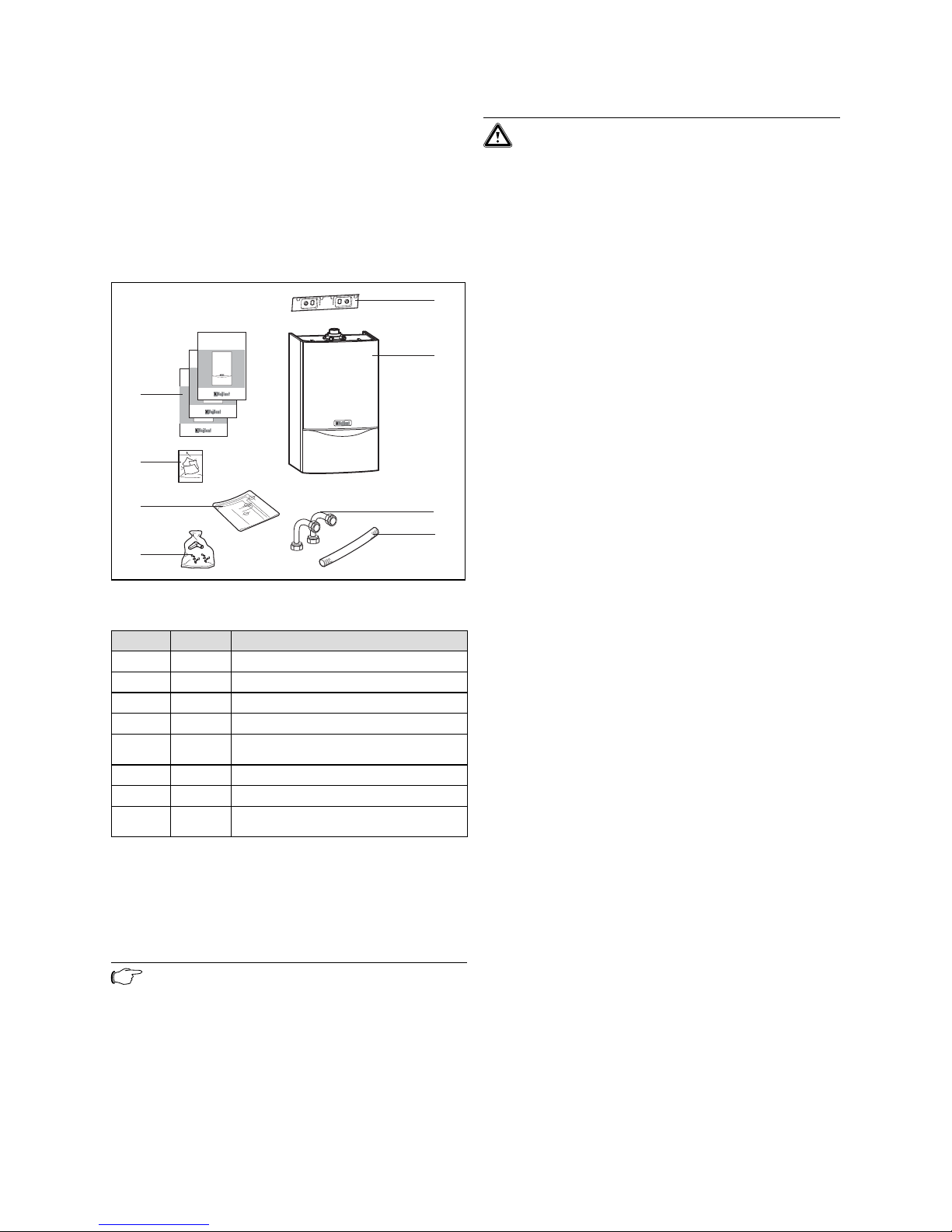
3.1 Scope of delivery and accessories
Scope of delivery
Check that all the parts have been delivered intact (see
fig. 3.1 and table 3.1).
1
2
3
5
6
7
8
4
Fig. 3.1 Scope of delivery
Position Quantity Name
1 1 Boiler hanging bracket
2 1 Boiler
3 2 Connector - storage charging circuit
4 1 Condensate discharge hose
5 1 Bag with fixing screws, wall plugs and
washers
6 1 Boiler installation template
7 1 Guarantee registration and envelope
8 3 Manuals: Installation and user instruc-
tions, flue installation instructions
Table 3.1 Scope of delivery
3.1.1 Unpack the boiler
To unpack the boiler, cut both plastic carton straps,
open box and lift out the polystyrene top packing. Lift
the cardbox upwards.
Note!
Care should be taken not to scratch the white
surface of the boiler casing.
3.2 Installation site
Please note the following safety instructions below before choosing where to install the appliance:
Caution!
Do not install the appliance in rooms prone to
frost. In rooms with aggressive steam or dust,
the appliance must be operated independently
of the ventilation!
When choosing the place of installation and while operating the appliance, make sure that the combustion air
is technically free of chemical substances containing fluorine, chlorine, sulphur etc. Sprays, solvents and cleaning agents, paints, adhesives etc. contain these kinds of
substances, which - in the worst case scenario - can lead
to corrosion, even in the exhaust system, during ambient air dependent operating of the appliance.
The appliance must be operated independently of the
ambient air particularly in hairdressing salons, carpenter‘s shops or paint shops, cleaning companies. Otherwise, a separate installation room is required to guarantee that the combustion air supply is technically free of
the above mentioned substances.
3.2.1 Select position of boiler
Refer to section ‘Boiler location’ for information regarding siting the appliance. In general the boiler must be
positioned such that:
• There is adequate space around the boiler for service
and maintenance
• The boiler can be correctly flued, i.e. the flue terminal
position is sited in accordance with these instructions
and the air/flue duct can be installed in accordance
with the flue installation instructions supplied.
• All necessary pipework can be connected, including
the pressure relief valve and condensate drain.
3.2.2 Air supply
Detailed recommendations for air supply are given in
BS 5440: Part 2. It is not necessary to have an air vent in
the room or internal space in which the boiler is installed.
3.2.3 Compartment ventilation
The boilers are very high efficiency appliances. As a consequence the heat loss from the appliance casing during
operation is very low. Compartment ventilation is required if the flue used is not concentric and air is supplied
from the room or compartment the boiler is installed in.
3.2.4 Electrical supply
A 230 V, ~ 50 Hz single phase electricity supply fused to
3 Amp. must be provided in accordance with the latest edition of BS7671 (IEE Wiring Regulations) and any other local
regulations that may apply. In IE reference should be made
to the current edition of the ETCI rules. The method of
connection to the mains electricity supply must provide a
means of completely isolating the boiler and its ancillary
controls. Isolation is preferably by the use of a fused three
pin plug and unswitched shuttered socket outlet, both
complying with the requirements of BS 1363. Alternatively,
a 3 Amp. fused doublepole switch with a 3 mm contact
separation on both poles may be used.
9Installation and maintenance manual ecoMAX 646 / 0020020158_02
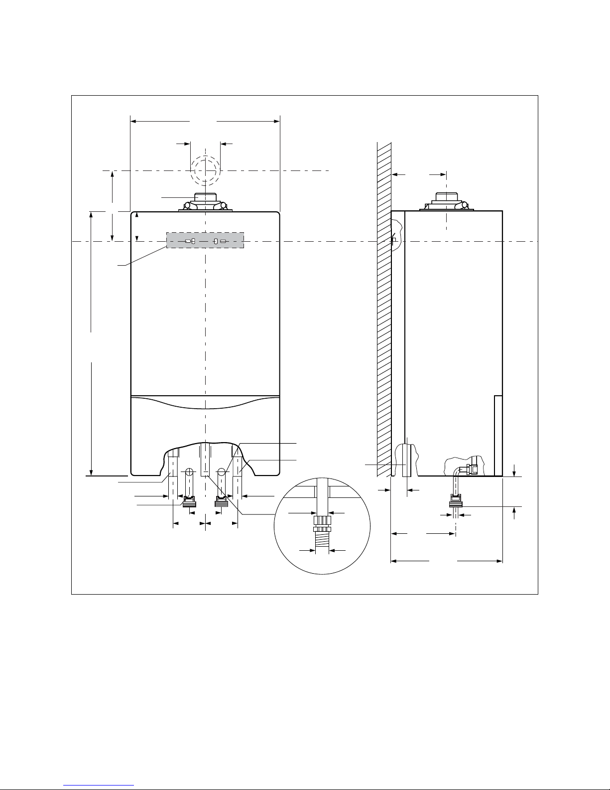
3.3 Dimensional drawing and connections
70
190
480
800
2
100
144
450
7
100 100
Rp1 Rp1
5
3
7
R
3
/
4
fl 20
R 1
180
4
94
1
A
fl 80/125
6
Fig. 3.2 Connection dimensions
1 Flue connection Ø 80/125 mm
Dimension A with 87° elbow: 253 mm
2 Mounting bracket
3 Heating return
4 DHW primary return (only in conjunction with cylinder)
5 Gas connection
6 DHW primary flow (only in conjunction with cylinder)
7 Heating flow
Mounting 3
Installation and maintenance manual ecoMAX 646 / 0020020158_0210
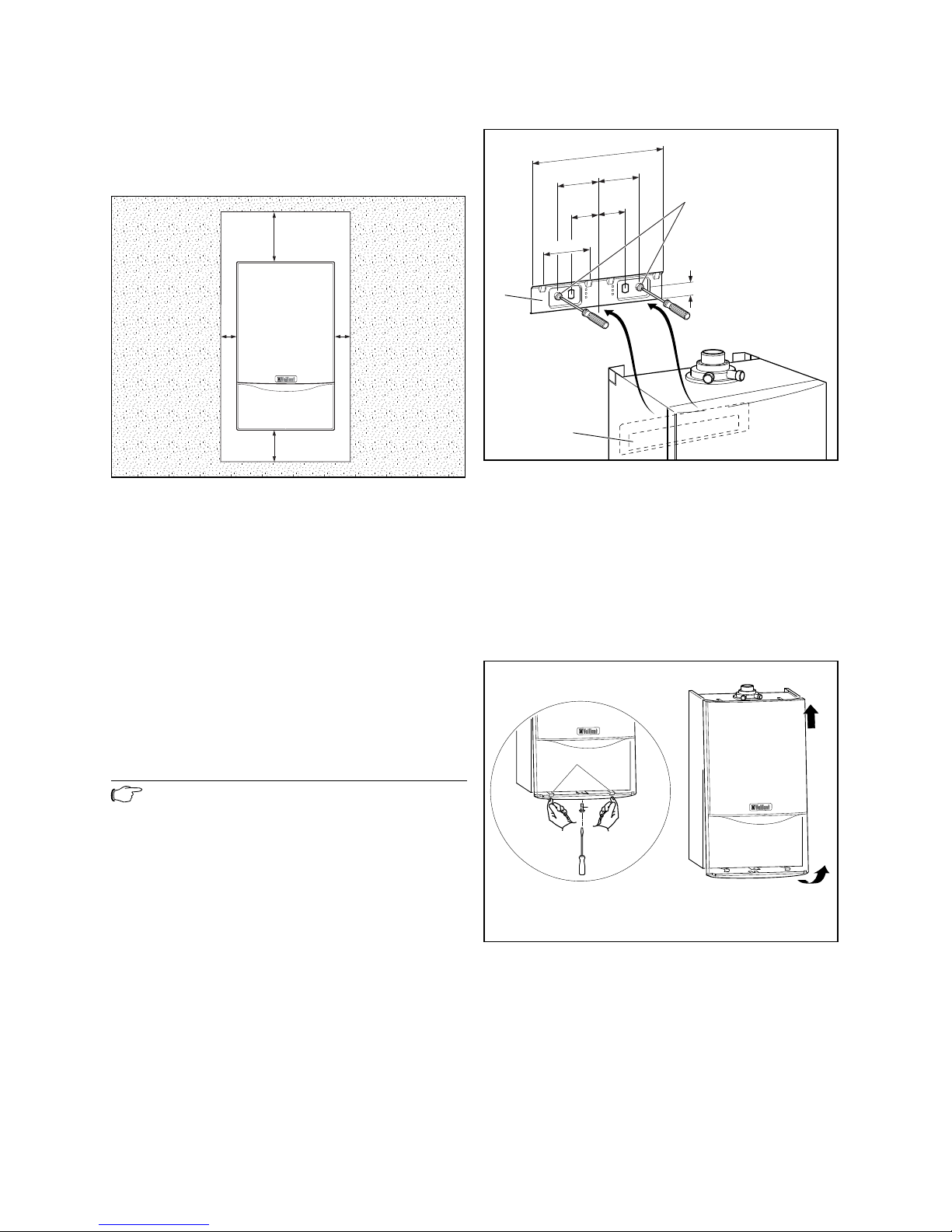
3.4 Required minimum gaps/assembly clearances
Both for the installation/assembly of the appliance and
for carrying out maintenance tasks later, you need the
minimum gaps and assembly clearances given below:
250
350
5
5
Fig. 3.3 Required minimum gaps/assembly clearances (mm)
Combustible materials may be safely placed next to the
appliance provided the minimum side clearance of 5 mm
is maintained for servicing, and if required ventilation
purposes. The external temperature of the appliance will
never be such as to cause combustion.
3.4.1 Using boiler template
• Fix the paper template to the wall ensure that the
template is vertical. The template shows:
- the position of the fixing holes for the boiler
mounting bracket
- the position of the connections
- the position of the flue exit hole
• Mark the position of the hanging bracket fixing holes.
• Drill 2 holes Ø 8 mm for the hanging bracket.
Note!
Use alternative fixing holes where necessary.
3.5 Mounting the appliance on the bracket
• Hang the appliance on o the mounting bracket (1) from
above with the bracket (3).
• Mount the cable connections to the appliance, making
sure they are disconnected from the power supply.
85
50
240
75
75
23
50
3
1
2
Fig. 3.4 Mounting the appliance on the bracket
3.6 Removing/Attaching the appliance casing
Removing the casing
To dismount the front casing of the appliance, proceed
as follows:
• Loosen the screw (1) on the bottom of the appliance.
• Press in both retaining clips (2) on the bottom of the
appliance so that the casing is released.
• Pull the casing (3) forwards by its bottom edge and lift
the casing up and off (4).
1
2
4
3
Fig. 3.5 Removing/Attaching the appliance casing
Attaching the casing
To mount the casing, proceed as follows:
• Place the casing on the upper appliance ensuring that
the casing and appliance lips engage.
• Push the casing onto the appliance so that the retaining clips (2) on the casing click into place.
• Fix the casing by tightening the screw (1) on the bottom of the appliance.
3 Mounting
11Installation and maintenance manual ecoMAX 646 / 0020020158_02
4 Installation
When installing, please observe the following points in
particular:
• Install the filling loop or other device in the return
• Ensure that the design of the system incorporates
a suitably sized by-pass or low loss header is installed
(as specified in paragraph 4.2)
When used with direct connection to an indirect DHW
cylinder using the connections provided:
• Install a primary loading pump
• Install a non-return valve in both heating and DHW
primary flows to prevent reverse circulation
• please also refer to section 4.3
4.1 Preparing the installation
Safety equipment for an emergency
• The outlet of the pressure relief valve must be suitably
terminated in accordance with BS 6798 or BS 6644.
• The boiler is suitable for connection to plastic central
heating pipes. It is preferred that the connections to
the boiler are made in copper for the first 1.5 metres
prior to the transition to plastic.
• Should a system be found to include non-oxygen barrier
pipe then it is essential that a plate heat exchanger be
installed in between the boiler and the non-oxygen
barrier pipe. It is essential that the boiler and the system have provision for water make up and expansion.
4.2 Technical instructions for the heating system
Caution!
The schematics shown are for diagrammatical
representation only – the system may demand
further safety devices and depends fully on the
control system employed. Unvented cylinders
must comply with the requirements of Building
Regulations Document G 3.
Always refer to British Standards, Good Practice Guides and CIBSE guidelines
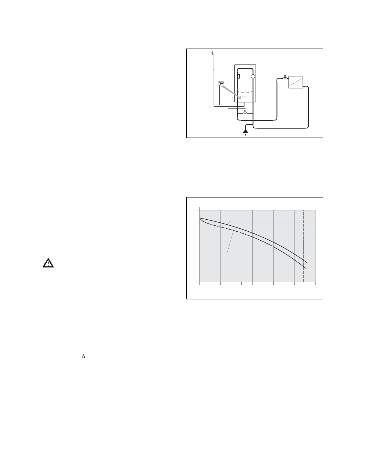
4.2.1 Direct connection to the heating circuit using
the integral boiler pump.
Pump layout; system dimensioning
The design flow rate of the ecoMAX 46 is optimally:
V = 2000 l/h at T = 20 K
flows through the boiler and system.
The resulting residual delivery head for the system design
is to be taken from fig. 4.2.
Setting the by-pass valve
In order to guarantee the minimum circulating water
volume of 1150 l/h through the appliance, a by-pass
valve must be fitted as a minimum requirement.
If an automatic type by-pass valve is fitted the operating
pressure should be able to be set between 250-400 mbar.
1
2
53
230V~
3
3
3
OS
Fig. 4.1 Example 1: radiator heating, direct feeding, integral
boiler pump
1 ecoMAX 646
2 integral boiler pump
53 automatic by-pass valve (not supplied)
OS outside sensor
0
900
Pressure [mbar]
Volume flow [l/hr]
800
700
600
500
400
300
200
100
850
750
650
550
450
350
250
150
50
0 200 400 600 800 1000 1200 1400 1600 1800 2000 2200
residual delivery head without non-return valve
residual delivery head with non-return valve
Design point
(accessory. art-no. 306 715)
Fig. 4.2 Resulting characteristic curve (residual delivery head)
ecoMAX 646
4.2.2 Connection to heating circuit containing
a low loss header.
Pump layout in the primary circuit
The pump output must be set to 100% (in the DIA system under point d.14).
Selection of the low loss header
A suitable WH model hydraulic switch (accessory) can
be selected with the aid of table 4.1.
A sufficiently large water volume (minimum circulating
water volume) is constantly supplied through the boiler
via the low loss header in conjunction with the pump
built into the boiler.
Installation 4
Installation and maintenance manual ecoMAX 646 / 0020020158_0212
heating system output
heating system spread
10 K 15 K 20 K
ecoMAX 646 WH 95 WH 40 WH 40
double cascade WH 160 WH 95 WH 95
triple cascade WH 280 WH 160 WH 160
quadruple cascade WH 280 WH 160 WH 160
Table 4.1: Selection of the low loss header, WH model
J
J
45
17a
2
1
3
3
3
2
3
3
4
2
230V~
3
3
3
13
13a
OS
Fig. 4.3 Example 2: radiator heating and floor heating, low loss
header, appliance-internal pump
1 ecoMAX 646
2 integral boiler pump
13 weather-compensated controller VRC 630
13a mixer valve
17a supply temperature sensor
45 low loss header
OS outside sensor
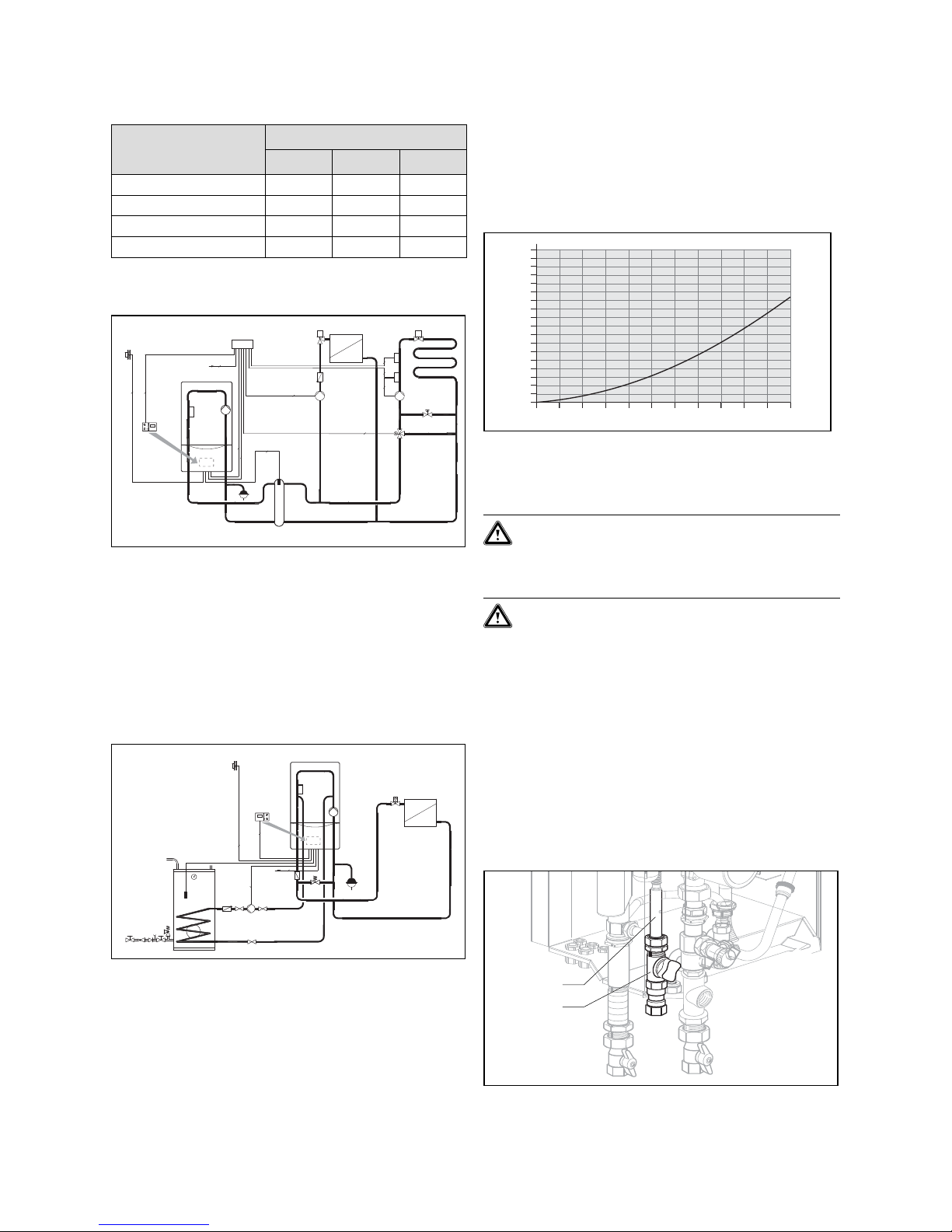
4.3 Technical instructions for recharging
1
2
230V~
3
3
3
3
13
OS
Fig. 4.4 Example 3: direct heating circuit and indirect cylinder
schematic
1 ecoMAX 646
2 integral boiler pump
13 weather-compensated controller VRC 410
OS outside sensor
Cylinder connection specification
It is imperative to keep to the minimum volume flow of
the charging circuit of 1800 l/h.
When designing such a system, consideration must be
made for the pressure losses of non-return valves and
piping to the cylinder.
0
900
Pressure [mbar]
Volume flow [l/hr]
800
700
600
500
400
300
200
100
850
750
650
550
450
350
250
150
50
0 200 400 600 800 1000 1200 1400 1600 1800 2000 2200
Fig. 4.5 Pressure loss characteristics of connecting a DHW
cylinder
4.4 Gas connection
Caution!
Ensure a stress-relief assembly of the gas
pipes to avoid leakages.
Caution!
Risk of damaging the gas control block by
exceeding the testing pressure. The gas control
block may only be tested for leaks up to a
maximum pressure of 110 mbar. The operating
pressure may not exceed 60 mbar. If these
pressures are exceeded, the electronic gas
valve may be damaged.
The appliance must be connected to your gas line via
a gas cock.
• Screw the appliance‘s gas supply pipe (1) gas-tight
with the gas cock (2). To do this, use the R3/4 compression fitting supplied with the appliance. This is
suitable for the connection of a R3/4 gas cock.
• Inspect the gas connection for leakage.
2
1
Fig. 4.6 Gas connection
4 Installation
 Loading...