

Page 1
Operating Instructions
<Basics>
Installation Instructions provided
HD Integrated Camera
Installation
Instructions
Model No.
AW-HE120WP
AW-HE120KP
AW-HE120WE
AW-HE120KE
Die Bedienungsanleitung in Deutsch
ist als PDF-Datei in der CD-ROM
enthalten.
Le mode d’emploi en français est
fourni sous forme de fichier PDF sur
le CD-ROM.
Le istruzioni per l’uso in italiano sono
contenute in un file PDF sul CD-ROM.
Las instrucciones de funcionamiento
en español se encuentran en un
archivo PDF del CD-ROM.
Документ Инструкция по эксплуатации
на русском языке находится в виде
PDF-файла на диске CD-ROM.
Operating
Instructions
Before useParts and
Before operating this product, please read the instructions carefully and save this manual for future use.
How the Operating Instructions are configured
<Basics> (this manual):
This <Basics> describes the procedure for basic operation and installation. Before installing this unit, be
sure to take the time to read through <Basics> to ensure that the unit will be installed correctly.
This manual <Basics> is also contained as a PDF file on the CD-ROM supplied with the unit.
<Operations and Settings>:
The <Operations and Settings> describes how to operate the unit and how to establish its settings.
The <Operations and Settings> is contained as a PDF file on the CD-ROM supplied with the unit.
Adobe
It can be downloaded from the home page of Adobe Systems.
FJ1111MS0 -FJ
Printed in Japan
®
Reader® is required to read PDF files.
ENGLISH
VQT3U65
their functions
PreparationReference
Page 2

ENGLISH
How to open the operating instruction manual PDF
files
Discontinue installation if the installation screen of the
software opens as a result of inserting the CD-ROM.
When [INDEX.pdf] on the CD-ROM is opened, a list of the
operating instruction manuals will be displayed.
Click on the document name of the manual to be opened.
Adobe
®
Reader® is required to read PDF files.
It can be downloaded from the home page of Adobe
Systems.
DEUTSCH
Öffnen der PDF-Dateien der Bedienungsanleitung
Brechen Sie die Installation ab, falls beim Einlegen der
CD-ROM der Installationsbildschirm der Software
erscheint.
Wenn [INDEX.pdf] auf der CD-ROM geöffnet wird,
erscheint eine Liste der Bedienungsanleitungen.
Klicken Sie auf den Dokumentennamen der zu öffnenden
Anleitung.
Zum Lesen der PDF-Dateien benötigen Sie Adobe
Reader
®
.
Dieses Programm kann von der Homepage von Adobe
Systems heruntergeladen werden.
FRANÇAIS
Comment ouvrir les fichiers PDF des manuels du
mode d’emploi
Arrêter l’installation si l’écran d’installation du logiciel
s’ouvre quand le CD-ROM est inséré.
Quand [INDEX.pdf] sur le CD-ROM s’ouvre, la liste des
manuels du mode d’emploi s’affiche.
Cliquer sur le nom du document correspondant au manuel
à consulter.
Adobe
®
Reader® est nécessaire pour lire les fichiers
PDF.
Ce logiciel peut être téléchargé depuis la page d’accueil
d’Adobe Systems.
ESPAÑOL
Modo de abrir los archivos PDF que contienen el
manual de las instrucciones de funcionamiento
Interrumpa la instalación si la pantalla de instalación del
software se abre como resultado de insertar el CD-ROM.
Cuando se abra [INDEX.pdf] en el CD-ROM se
visualizará una lista de los manuales de instrucciones de
funcionamiento.
Haga clic en el nombre de documento del manual que va
a abrir.
Para leer los archivos PDF se necesita el programa
®
Adobe
Reader®.
Este programa se puede descargar de la página inicial de
Adobe Systems.
РУССКИЙ
Как открыть PDF-файлы инструкции по
эксплуатации
Прекратите установку, если в результате загрузки
диска CD-ROM появилось окно установки
программного обеспечения.
®
При открытии файла [INDEX.pdf] на диске CD-ROM
будет отображен список инструкций по эксплуатации.
Щелкните название документа руководства, чтобы
открыть его.
Для чтения PDF-файлов потребуется Adobe
Reader
®
.
®
Данное программное обеспечение можно скачать с
домашней страницы Adobe Systems.
ITALIANO
Come aprire i file dei manuali di istruzioni per l’uso
Se inserendo il CD-ROM si apre la schermata di
installazione del software, interrompere l’installazione.
Aprendo [INDEX.pdf] sul CD-ROM, viene visualizzato un
elenco di manuali di istruzioni per l’uso.
Fare clic sul nome del documento corrispondente al
manuale da aprire.
Per leggere i file PDF è necessario Adobe
®
Reader®.
Il programma può essere scaricato dal sito Web di Adobe
Systems.
2
Page 3
Trademarks and registered trademarks
Abbreviations
Microsoft, Windows, Windows Vista, Windows 7 and
Internet Explorer are either registered trademarks or
trademarks of Microsoft Corporation in the United States
and other countries.
Intel and Intel Core are trademarks or registered
trademarks of Intel Corporation in the United States and
other countries.
Adobe and Reader are either registered trademarks or
trademarks of Adobe Systems Incorporated in the United
States and/or other countries.
HDMI, the HDMI logo and High-Definition Multimedia
Interface are the trademarks or registered trademarks
of HDMI Licensing, LLC in the United States and other
countries.
Other names of companies and products contained
in these Operating Instructions may be trademarks or
registered trademarks of their respective owners.
About copyright and licence
Distributing, copying, disassembling, reverse compiling,
reverse engineering, and also exporting in violation of export
laws of the software provided with this unit are expressly
prohibited.
The following abbreviations are used in this manual.
Microsoft
®
Windows® 7 Professional SP1 32/64-bit is
abbreviated to “Windows 7”.
Microsoft
®
Windows Vista® Business SP2 32-bit is
abbreviated to “Windows Vista”.
Microsoft
Windows
®
Windows® XP Professional SP3 and Microsoft®
®
XP Home Edition SP3 are abbreviated to
“Windows XP”.
Windows
Explorer
®
Internet Explorer® 8.0 and Windows® Internet
®
9.0 are abbreviated to “Internet Explorer”.
For the purposes of this manual, the model numbers of the
units are given as listed in the table below.
Model number
of unit
AW-HE120WP
AW-HE120KP
AW-HE120WE
AW-HE120KE
AW-HS50N
AW-HS50E
AW-PS550N
AW-PS550E
AW-RP50N
AW-RP50E
AW-RP555N
AW-RP555L
AW-RP655N
AW-RP655L
Model number
given in manual
AW-HE120
AW-HS50
AW-PS550
AW-RP50
AW-RP555
AW-RP655
Illustrations and screen displays featured in the
manual
What is shown in the manual’s illustrations and screen
displays may differ from how it is actually appears.
3
Page 4

Contents
Installation Instructions
Read this first! ..................................................................5
Installation precautions ...................................................6
How to install and connect the unit ................................8
When using the WV-Q105 (optional accessory) ..........12
Changing the direction of the nameplate .....................13
Removing the camera ....................................................14
Stand-alone installation
(when the mount bracket is going to be used)........15
Stand-alone installation
(when the mount bracket is not going to be used)
When installing the unit on a desktop ..........................17
When mounting the unit on a tripod .............................17
...17
Connections ....................................................................18
Connections with an HD monitor .................................18
Connections with a controller
(AW-RP655 or AW-RP555) ........................................19
System example 1 (Serial control) ...............................20
System example 2 (IP control) .....................................21
Appearance .....................................................................22
Operating Instructions
Read this first! (For AW-HE120WP, AW-HE120KP) ......23
Read this first! (For AW-HE120WE, AW-HE120KE) ......25
Before use .......................................................................28
Overview ......................................................................28
Required personal computer environment ...................28
Disclaimer of warranty..................................................29
Network security ..........................................................29
Characteristics ................................................................30
Controller supported ......................................................31
Accessories ....................................................................31
Operating precautions ...................................................32
Concerning the wireless remote control
(optional accessory) ..................................................34
Parts and their functions ...............................................35
Camera unit .................................................................35
Wireless remote controller (optional accessory) ..........37
Setting the remote control IDs ......................................39
Network settings .............................................................40
Installing the software ..................................................40
Use the Easy IP Setup Software
to establish the unit’s settings ....................................40
Troubleshooting ..............................................................42
Specifications .................................................................48
Index ................................................................................50
4
Page 5
Read this first!
WARNING:
To prevent injury, this apparatus must be securely
attached to the floor/wall in accordance with the
installation instructions.
WARNING:
Installation should only be performed by qualified
installation personnel.
Improper installation may result in the entire
apparatus falling down and causing injury.
indicates safety information.
CAUTION:
This camera intended for use only with the Mount
Bracket enclosed with the unit and Panasonic
Direct Ceiling Mount Bracket, WV-Q105.
Use with other apparatus is capable of resulting
in instability causing possible injury.
Installation
Instructions
5
Page 6
Installation precautions
To installation personnel
Read the Instructions thoroughly and then perform the operation correctly and safely.
Also, always read the “Read this first!” on page 5 of this manual as they contain important information.
After the installation, give this Instruction manual to the customer to save for future use.
Ensure that the installation work complies with the
technical standards governing electrical equipment.
This unit is for indoor use only.
It cannot be used outdoors.
Avoid installation in a location where the unit will be exposed
to direct sunlight for extended periods or near a cooling or
heating appliance.
Otherwise, deformation, discoloration, malfunctioning and/or
problems in operation may result. Operate the unit where it
will not be splashed or sprayed by water.
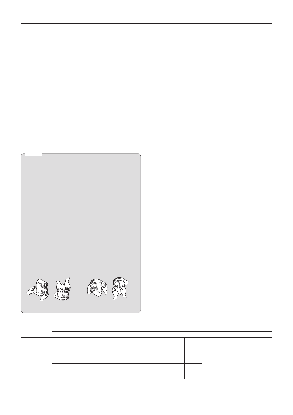
Use the unit with an installation where the unit is
suspended from an overhead surface or with a
stand-alone installation.
Do not use the unit on its side or tilted at an angle.
Notes
Be absolutely sure to use the four bracket mounting
screws (M4) for mounting the mount bracket.
These are supplied with the unit. Do not use wood
screws, nails, etc.
In the case of a concrete ceiling, secure the unit using
anchor bolts (for M4) or AY plug bolts (for M4).
Recommended clamping torque
M4: 1.47 N · m {15 kgf · cm}
The withdrawal strength of the mounting location for
each screw must be at least 294 N {30 kgf}.
When mounting the unit on a ceiling made of
plasterboard, for instance, if it is not strong enough
to support its weight, either reinforce the ceiling
adequately or use the WV-Q105 direct ceiling mount
bracket, which is sold separately.
When using a mount bracket which is sold separately,
read the handling instructions.
Do not hold the camera head while undertaking the
installation work. Doing so may cause malfunctioning.
Concerning the installation location
Install the unit in a stable location which will not be
susceptible to shaking. If the unit is installed in a location
which is susceptible to shaking, this will cause the unit’s
images to shake in turn.
Install the unit after conferring in detail with your dealer.
Install the unit on a ceiling that is strong enough (such as a
concrete ceiling).
If the unit is to be installed on a ceiling which is not strong
enough, reinforce the ceiling sufficiently first.
Do not install or use the unit in the following kinds of
locations.
On walls (where the unit would be installed sideways)
In locations (including places such as under the eaves of
a building) where the unit would be directly exposed to
rain or water
In locations such as kitchens where there are high
concentrations of steam and grease
In outdoor locations or hot places where the temperature
will exceed 40 °C (104 °F)
In cold locations where the temperature will drop below
0 °C (32 °F)
In locations where the humidity will exceed 85 %
In locations where chemicals are used such as near
swimming pools
At sea, in coastal areas or in locations where corrosive
gases are emitted
In locations where radiation, X-rays, or strong radio waves
or magnetic fields are generated
In locations where the unit would be subject to a great
deal of vibration such as on board a vehicle or ship (this
unit is not designed to be used in vehicles)
In locations where the temperature is subject to sudden
changes such as near the air outlet of an air conditioner or
near a door which allows the outside air to come in
OK NGOK NG
Desktop installation Hanging installation
AW-HE120
main unit
Mass Model No. Mass Mounting
Direct mount
Approx.
3.0 kg [6.61 lbs]
(Including
mount bracket)
accessory)
WV-Q105
accessory)
6
Applicable mount bracket Mounting onto the ceiling
(supplied
(optional
Approx.
0.4 kg
[0.88 lbs]
Approx.
0.15 kg
[0.33 lbs]
Hanging/Desktop
For ceiling
What to avoid to ensure that the unit will perform stably
over a prolonged period
Using the unit for a prolonged period in a location with
high temperature and humidity levels will cause its parts to
deteriorate and shorten its service life.
Ensure that a cooling unit or heating unit will not blow any
air directly toward the installation location.
Mounting conditions
Recommended
screws
M4 screws
(supplied
accessory)
M4 screws
(supplied with the
WV-Q105)
No. of
screws
4
4
Minimum withdrawal strength
(per screw)
294 N {30 kgf}
Ensure that the mounting strength
can support a weight that is at least
five times the total mass of the
equipment, including the camera’s
main unit.
Page 7
Installation precautions
(continued)
Before installation, always disconnect the power plug
When installing, always use the supplied components.
Do not disassemble or modify the wall mount adaptor.
Be absolutely sure to use the supplied brackets and
screws to install the camera.
Do not mount the unit by employing any methods other
than those specified.
Do not remodel the mounting bracket or mounting screws
provided with the unit.
Tightening up the mounting screws
Tighten up the screws and bolts securely to the degree
that is appropriate for each of the materials used in the
mounting location and structures.
After tightening up the screws and bolts, check that there
is no unsteadiness and that the parts have been tightened
securely.
Use the specified tools and tighten the screws firmly.
When the unit is no longer going to be used, do not
leave it lying around, but be absolutely sure to dispose
of it properly.
For details on how to remove the unit, refer to “Removing the
camera” (page 14).
Power switch
This unit does not have a power switch. The power turns
on when its power plug is connected to a power outlet.
When the power is turned on, the pan, tilt, zoom and
focusing operations are performed. Before proceeding with
maintenance, be absolutely sure to disconnect the power
plug from the power outlet.
Connecting the power cable
Be absolutely sure to connect the power cable of the
AC adaptor through a circuit breaker using one of the
following methods.
(1) Connect the power cable through a power control unit.
(2) Connect the power cable to a circuit breaker in a
power distribution panel with a contact distance of
3.0 mm or more.
Use a circuit breaker which is capable of shutting
off all the poles of the main power supply with the
exception of the protective ground conductor.
(3) Install the AC adaptor near the power outlet, and
connect it through the power plug.
Grounding
Before using the unit, check that the grounding
wire has been fastened securely.
Installation
Instructions
When installing, transferring or disposing of the unit, be
absolutely sure to hold it by its pedestal area.
Problems may result if the camera head is held or rotated.
Do not attach a filter, hood, extender or other parts to the
unit.
Use the dedicated AC adaptor and power cable provided
with the unit.
Connect the AC adaptor and power cable to the power inlet
securely.
Installing the AC adaptor
Do not place the adaptor directly onto a ceiling panel or
other such surface.
Extreme danger is posed when water has collected on the
surface as a result of leaking rain, for instance.
Secure the adaptor firmly to the bottom or other surface of
a reinforcing member made of channel steel where dust
and other foreign matter will not accumulate.
(Refer to page 12.)
Secure the adaptor firmly so that there will be no chance
that it will fall off or fall down.
Secure it using a strength which can withstand the mass
(approx. 0.3 kg [0.66 lbs]) of the AC adaptor.
If there is a possibility of noise interference
Either wire the cables so that the power cable (ceiling light
cord) of AC 100 V or more, and the signal cable are placed
at least 1 meter (3.3 ft) apart. Alternatively run each cable
through its own metal conduit. (The metal conduits must be
grounded.)
Radio signal interference
If the unit is positioned near a TV or radio transmitting
antenna or a strong electrical field or magnetic field (such as
that generated by a motor, transformer or power lines), its
images may be distorted and/or the images may be affected
by noise.
When connecting the cables, ensure that the connector
areas will not be subject to any load.
Doing so may cause malfunctioning.
Allowing the generated heat to escape
This unit allows the heat generated inside to escape from its
surfaces.
Do not install the unit in a location where it will be surrounded
by walls or other surfaces and where heat will be trapped.
In addition, the heat is dissipated to the bottom panel which
will warm up over time: This is normal and not indicative of
any trouble.
Install the accessory AC adaptor near the main power
outlet, and position it in such a way that its power plug
can be plugged into and unplugged from the outlet easily.
When connecting the AC adaptor to a power outlet on the
ceiling or on any other surface where dust may collect, wipe
off the dust on the power plug at periodic intervals as an
anti-tracking measure.
Panasonic does not accept any responsibility
for accident or damage during installation if
procedure in this manual is not followed.
7
Page 8
How to install and connect the unit
Be absolutely sure to read through the “Read this first!” (page 5) and “Installation precautions” (pages 6 to 7).
The procedure given here is for the kind of installation where the unit is suspended from an overhead surface, but the same
steps are followed for a stand-alone installation.
If the ceiling panel is not strong enough to bear the unit’s weight, use the kind of mount bracket that is supported
by anchor bolts between the concrete ceiling and ceiling panel. The unit supports the WV-Q105 direct ceiling mount
bracket which is used solely for combination cameras. Use this bracket to install the unit. (See page 12)
In a case like this, the holes (ø 60 mm [ø 2-3/8 inches]) for installing the direct ceiling mount bracket on the ceiling
must be drilled in the ceiling panel.
It is also recommended that you provide an inspection space or opening for access purposes in the area near where
the equipment is installed in order to facilitate installation and the wiring connections work.
See page 31 for details of the accessories.
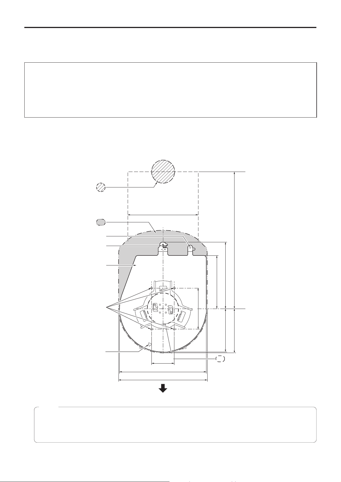
1 Check the mounting space.
Refer to the illustration, and determine where the unit is to be installed and in which direction it should be mounted.
Factor in the unit mounting area and include space for the wires extending from its rear panel.
The asterisk () in the illustration marks the position and dimensions of the hole for mounting the mount bracket.
Unit: mm (inch)
Through-hole for cable
ø 40 mm (ø 1-9/16 inches)
(reference)
(Space for the wires from the
160 (6-5/16)
rear panel)
Unit mounting area
Hole for mounting the
main unit mounting screw
Hook for mounting the
drop-prevention wire
Mount bracket
) Holes for mounting the
(
mount bracket: ø 4.5 mm 4
Hole for checking the positioning
()83.5
(3-9/32)
176 (6-15/16)
180 (7-3/32)
108 (4-1/4)
()46 (1-13/16)
(Space for the wires)
320 (12-19/32) or more
88 (3-15/32) 136 (5-11/32)
90 (3-17/32)
Hole for installing the WV-Q105
direct ceiling mount bracket
[ø 60 mm (ø 2-3/8 inches)]
The front panel of the unit on this side.
Notes
Before proceeding to install and connect the main unit, connect the LAN cable, HDMI cable, VGA cable, AC adaptor
cable and coaxial cables in the space above the ceiling panel, and then pass the cables through the cable holes.
For a power outlet which is used on the ceiling, be absolutely sure to take measures to deal with the tracking that may
be caused by the accumulation of dust and other foreign matter.
8
Page 9
How to install and connect the unit
(continued)
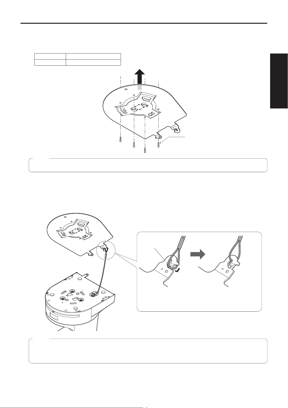
2 Mount the mount bracket onto the installation surface.
Use the bracket mounting screws (M4, bind-head: 10 mm long) supplied with the unit.
For proper clamping torque, securely attach the screws using the specified tools.
Screw diameter Clamping torque
M4 1.47 N · m {15 kgf · cm}
Bracket mounting screws 4 (supplied)
(M4, bind-head)
Installation
Instructions
Note
Use only the screws supplied with the unit. Do not use any other screws such as wood screws, nails, etc.
3 Attach the drop-prevention wire.
Loop the circle part of the drop-prevention wire, which has been attached to the bottom panel of the unit, around the end
of the hook part of the mount bracket.
Pull the drop-prevention wire, and check that it has been attached securely to the hook.
End of hook
Drop-prevention
wire
Loop the circle part of
the drop-prevention wire
around the end of the hook
part of the mount bracket.
Pull the wire, and check that
it is securely attached to the
hook.
Notes
Do not do this work while holding the camera head since doing so may result in malfunctioning of the unit.
The drop-prevention wire is designed to be used for installation where the unit is suspended from an overhead
surface so do not subject it to the weight of units other than the unit.
9
Page 10
How to install and connect the unit
(continued)
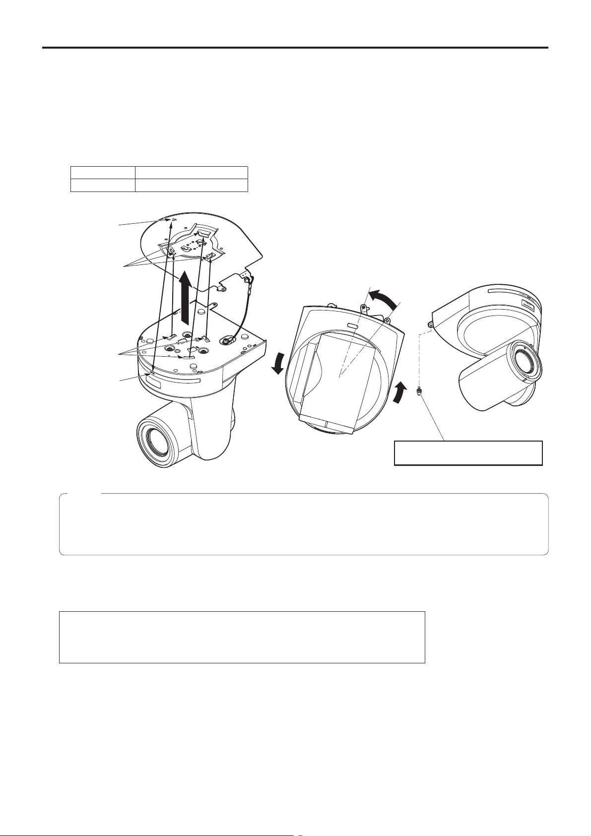
4 Mount the unit.
Align the position of the hole for checking the positioning with the status display lamp.
Align the holes on the camera main unit used to insert the bottom panel with the protrusions on the mount bracket used
for inserting the camera, push the bracket and camera firmly together, and rotate the main unit by about 20 degrees in
the direction of the arrow.
Secure the mount bracket to the unit using the main unit mounting screw (M3) as supplied.
Attach the mount bracket securely with the prescribed tool using the clamping torque below.
Be absolutely sure to verify that none of the screws are loose.
Screw diameter Clamping torque
M3 0.78 N · m {8 kgf · cm}
Hole for checking
the positioning
On the mount
bracket: Protrusions
(3) used for
inserting the camera
Approx.
20°
On the camera
main unit: Holes
(3) used to insert
the bottom panel
Status display lamp
Notes
Do not do this work while holding the camera head since doing so may result in malfunctioning of the unit.
Use only the screws supplied. Do not use any other screws.
Check that the unit has been mounted securely with no tilting or wobbling.
The unit must be secured without fail using the main unit mounting screw before any of the cables are connected.
5 Check the mounting.
Check out the following points.
• The main unit mounting screw must be mounted securely.
• The unit must not tilt, and it must be mounted exactly.
• The unit must be securely installed.
• The unit pedestal part must not rotate even when an attempt is made to turn it.
Main unit mounting screw (M3 screw)
(with flat washer, spring washer)
10
Page 11
How to install and connect the unit
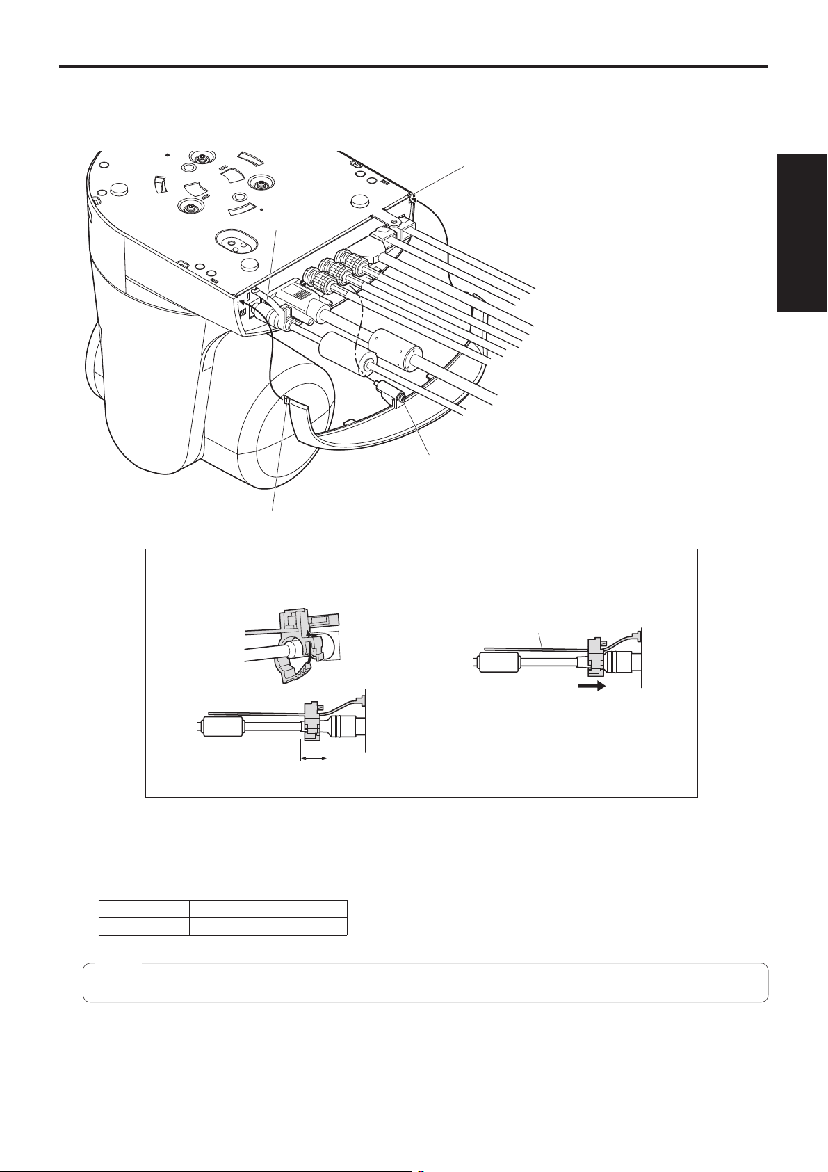
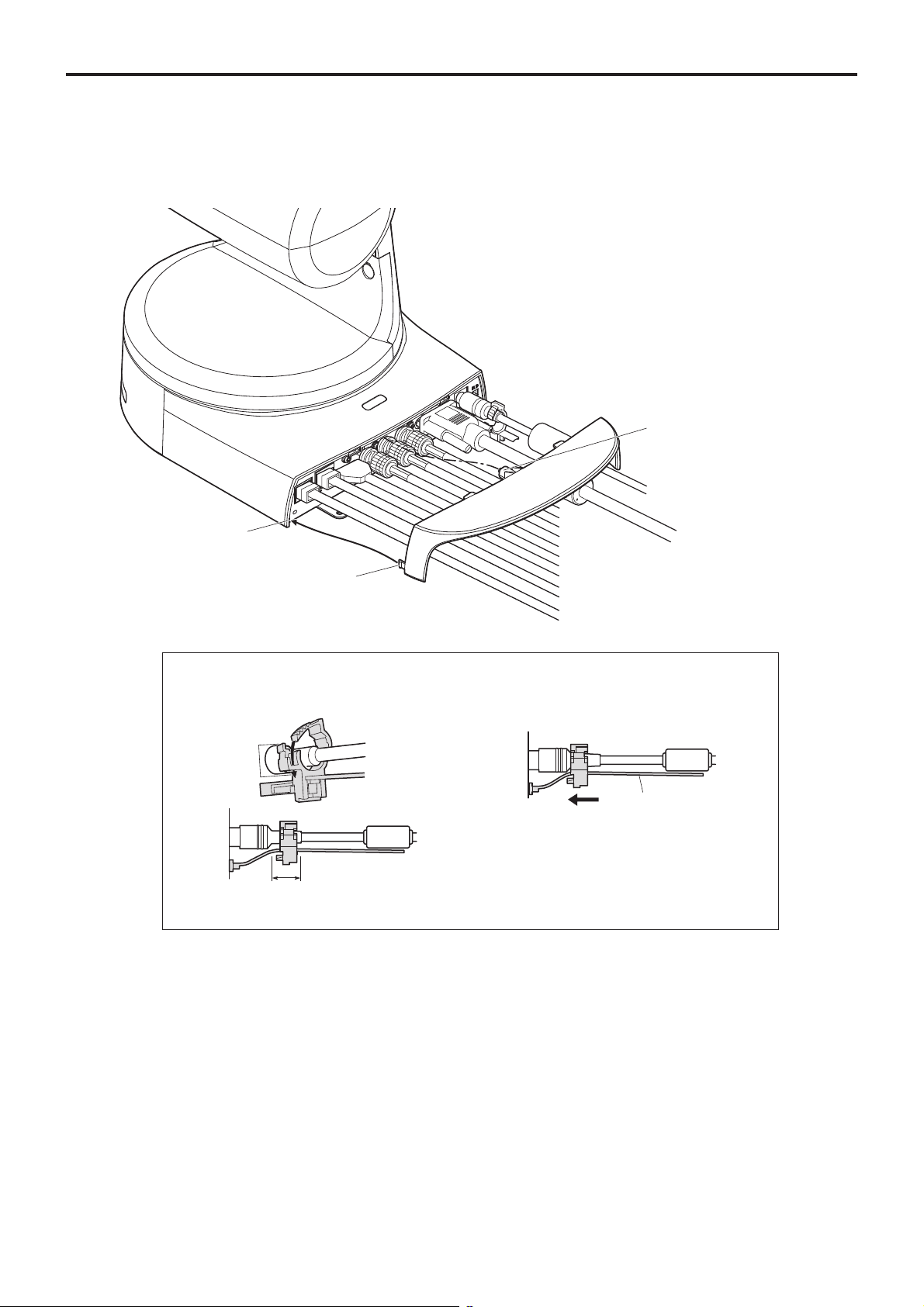
6 Connect the rear panel connectors.
Anchor the AC adaptor cable in place using the cable clamp.
Cable clamp
(continued)
Square hole (one at either side)
LAN cable
LAN cable
HDMI cable
Coaxial cable
Coaxial cable
Coaxial cable
VGA cable
AC adaptor cable
Installation
Instructions
Screw for cable cover (M3 screw)
(with flat washer, spring washer)
Tab (one at either side)
How to secure the DC plug
Loosely secure the cable clamp.
Cable clamp
Loosely secure the cable clamp
in the area shown above.
Fasten the cable clamp.
Strap part
Take hold of the strap part, slide
the cable clamp until it stops
moving, and then secure it tightly.
7 Attach the cable cover.
Fit the two tabs on the cable cover into the square mounting hole at either side of the rear panel.
Secure the cable cover using the screw (M3 20 mm) provided.
Screw diameter Clamping torque
M3 0.78 N · m {8 kgf · cm}
Note
Engage the tabs on the cable cover so they fit into place perfectly, and check that the cover is not rickety.
11
Page 12
How to install and connect the unit
(continued)
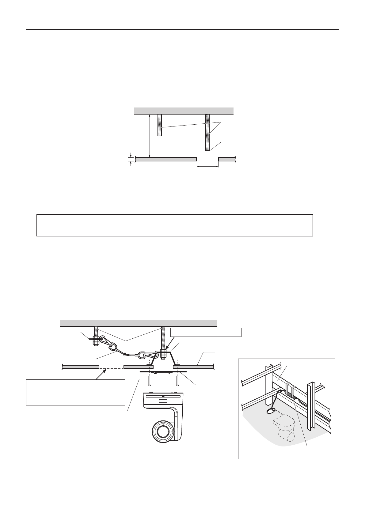
When using the WV-Q105 (optional accessory)
It is recommended that you provide an inspection opening or other such space for access purposes in the area near where the
equipment is installed in order to facilitate installation and the wiring connections work.
Before mounting the mount bracket, check that the installation location is strong enough to withstand the total mass
(approx. 3.0 kg [6.61 lbs]) which will be exerted once the camera is mounted.
Use the mount bracket where the space between the ceiling panel and the concrete ceiling is at least 100 mm high.
The bracket can be mounted where the thickness of the ceiling panel ranges from 5 mm to 40 mm.
The drop-prevention wire (supplied with the WV-Q105) must be used when mounting the direct ceiling mount bracket.
Concrete ceiling
Anchor bolts
Height above ceiling
panel: At least 100 mm
Ceiling panel (plasterboard, etc. with
a thickness from 5 mm to 40 mm)
ø 60 mm
Withdrawal strength: 294 N {30 kgf} or more
The anchor bolts must not protrude
beneath the ceiling panel.
1 Refer to the Operating Instructions of the WV-Q105 direct ceiling mount bracket, and attach the
WV-Q105 as well as the drop-prevention wire angle and drop-prevention wire supplied with the WV-Q105
to the anchor bolts.
Mounting the anchor bolts and direct ceiling mount bracket ()
This job is facilitated if the direct ceiling mount bracket is loosely secured to the ceiling panel in one place, and
the direct ceiling mount bracket and anchor bolts are vertically aligned before the nuts are tightened up.
2 First, remove the screws which were loosely fastened in step 1, and then align the camera mount
bracket of the AW-HE120 with the screw holes in the WV-Q105 direct ceiling mount bracket and mount it
in place.
Use the mounting screws (the M4-L60 Phillips head screws with adhesive) supplied with the WV-Q105 as the mounting
screws.
Fasten the AC adaptor securely to the bottom or other surface of the reinforcing member made of channel steel where
dust and other foreign matter will not accumulate.
Do not place the AC adaptor directly onto the ceiling panel or other such surface.
Space above the ceiling
Drop-prevention wire
angle (Supplied with
WV-Q105)
Drop-prevention wire
(Supplied with WV-Q105)
Inspection opening recommended
The installation and wiring connection
work is facilitated if an inspection
opening is provided for access purposes.
Anchor bolts
(): Fasten here using the nut.
Direct ceiling mount bracket WV-Q105 (optional accessory)
Plasterboard or other ceiling panel
Channel steel
Camera mount
bracket (Supplied
with AW-HE120)
Mounting screw 4
(Supplied with WV-Q105)
AW-HE120
( Ceiling
panel)
Secure the AC adaptor firmly to a
member made of channel steel.
3 Install the AW-HE120 camera by following the procedure starting with step 3 on page 9.
12
Page 13
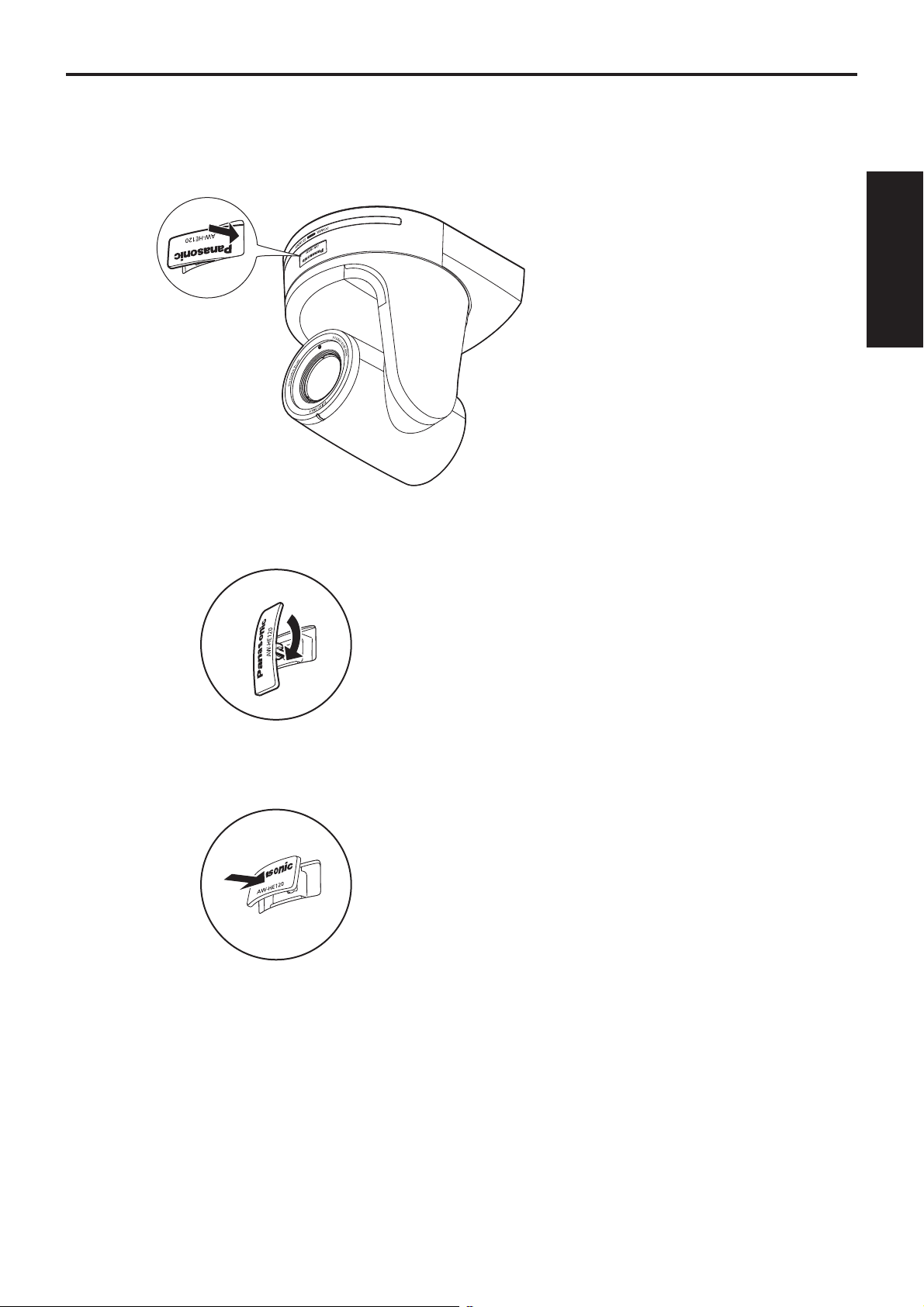
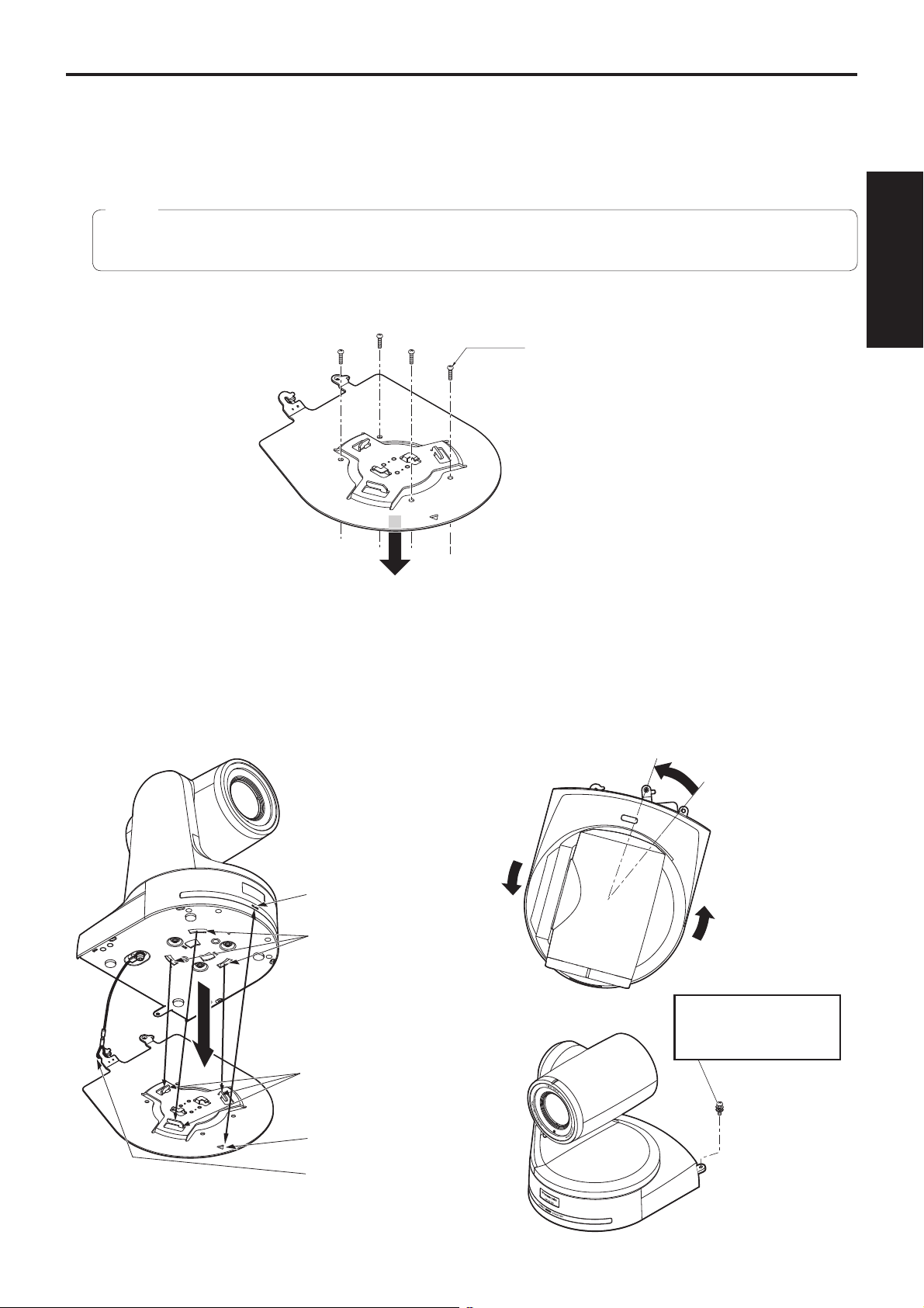
Changing the direction of the nameplate
When the unit is mounted on the ceiling, its nameplate will be upside down.
The direction of the unit’s nameplate can be changed.
1 Push in the part indicated by the arrow, and pull out the nameplate.
Installation
Instructions
2 Change the direction of the nameplate.
3 Push the nameplate back into place.
13
Page 14
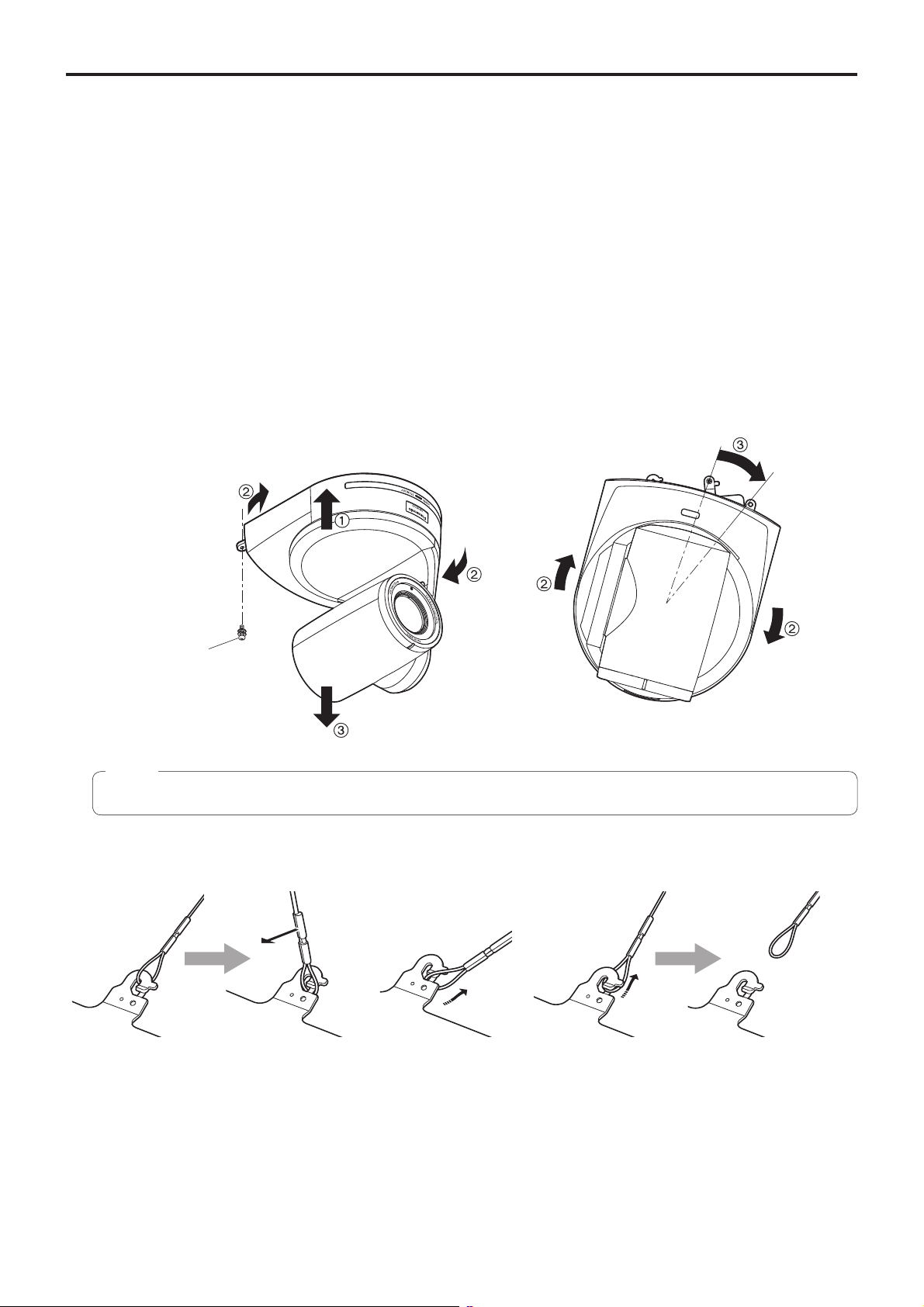
Removing the camera
1 Turn off the circuit breaker and power.
2 Remove the cable cover.
Remove the screw (M3) for the cable cover used to secure the cover.
Push the tab parts of the cover to disengage the cover.
3 Disconnect the cables.
Disconnect the power cable, video cable, and control cable, etc.
4 Remove the main unit mounting screw used to secure the unit and mount bracket.
5 Push the unit (). Turn it approximately 20 degrees away from the installed position (),
and remove it ().
Approx.
20°
Main unit mounting
screw (M3 screw)
(with flat washer, spring
washer)
Note
Do not do this work while holding the camera head since doing so may result in malfunctioning of the unit.
6 Disengage the drop-prevention wire from the mount bracket.
Pull the drop-
prevention wire in the
direction shown by the
arrow above.
Twist the wire, and
remove the wire loop
through the opening in
the hook.
Pull the wire in the
direction shown by the
arrow above, and simply
pull it out.
14
Page 15
Stand-alone installation (when the mount bracket is going to be used)
The same steps are followed as for the kind of installation where the unit is suspended from an overhead surface
(pages 8 to 11).
1 Check the mounting space.
Note
As with installing the unit suspended from an overhead surface, carefully check the space where the unit will be
mounted, and then decide if it is appropriate to install the unit in that space.
Installation
2 Mount the mount bracket onto the installation surface.
Bracket mounting screws 4 (supplied)
(M4, bind-head)
Instructions
3 Attach the drop-prevention wire.
4 Mount the unit.
Align the position of the hole for checking the positioning with the status display lamp.
Align the holes on the camera main unit used to insert the bottom panel with the protrusions on the mount bracket used
for inserting the camera, push the bracket and camera firmly together, and rotate the main unit by about 20 degrees in
the direction of the arrow.
Secure the mount bracket to the unit using the main unit mounting screw (M3) as supplied.
Approx. 20°
Status display lamp
On the camera main unit:
Holes (3) used to insert
the bottom panel
Main unit mounting screw
(M3 screw)
(with flat washer, spring
washer)
On the mount bracket:
Protrusions (3) used for
inserting the camera
Hole for checking the
positioning
Attach the drop-prevention
wire.
15
Page 16
Stand-alone installation (when the mount bracket is going to be used)
5 Check the mounting.
6 Connect the rear panel connectors.
Screw for cable cover (M3 screw)
(with flat washer, spring washer)
AC adaptor cable
(continued)
Square hole
(one at either side)
Tab (one at either side)
How to secure the DC plug
Loosely secure the cable clamp.
Cable clamp
Loosely secure the cable clamp
in the area shown above.
Coaxial cable
Coaxial cable
Coaxial cable
HDMI cable
LAN cable
LAN cable
Fasten the cable clamp.
Strap part
Take hold of the strap part, slide
the cable clamp until it stops
moving, and then secure it tightly.
VGA cable
7 Attach the cable cover.
16
Page 17

Stand-alone installation (when the mount bracket is not going to be used)
When installing the unit on a desktop
Place the unit flat on the surface.
Notes
Install the unit in a stable location which will not be susceptible to shaking. If the unit is installed in a location which is
susceptible to shaking, this will cause the unit’s images to shake in turn.
Take care not to allow the unit to fall or otherwise be damaged during installation.
When carrying the unit, do not hold it by its head.
Do not take hold of the camera head or rotate it. Doing so may cause malfunctioning.
Take care not to pull the connected cables. Doing so may cause the unit to fall and/or it may result in injury.
Installation
Instructions
Ensure that the unit will not fall off.
OK NG
When mounting the unit on a tripod
Attach the tripod to the threaded holes for mounting the camera on the camera’s bottom panel.
Place the tripod on a completely flat and level surface.
Tighten the screws by hand to mount the tripod securely.
Use screw for mounting the tripod that satisfy the following standard.
Screw for mounting tripod
1/4-20UNC, ISO1222 (6.35 mm)
4.5 mm to 6 mm
(0.18 inches to 0.24 inches)
Notes
Do not install the unit where people will be passing back and forth.
When using the unit mounted on a tripod, do not put the tripod high above the floor level.
Mount the unit securely so there is no looseness. Looseness may cause the unit to fall off and/or result in injuries.
When the unit is going to be used for a prolonged period of time, take steps to ensure that the unit will not topple or fall
over and that it will not fall off or fall down. After using the unit, restore the installation location to its original state without
delay.
17
Page 18

Connections
Connections with an HD monitor
HD monitor
HD Integrated Camera
AW-HE120
HDMI signal, HD-SDI signal or HD analog component signal
Wireless remote controller (optional accessory)
Up to four units can be operated using one remote control.
18
Page 19

Connections
(continued)
Connections with a controller ( AW-RP655 or AW-RP555)
LAN cable (straight cable)
Multi Hybrid
Control Panel
AW-RP555
Pan-tilt head/
camera control signals
DC cable with ø 5.5 plug
(supplied with the AW-PS550)
AC Adapter
AW-PS550
HD Integrated Camera
AW-HE120
HDMI/SDI/Analog video signal
Monitor
Accessory AC adaptor
Installation
Instructions
Multi-Function Controller
AW-RP655
AC Adapter
AW-PS550
19
Page 20

Connections
(continued)
System example 1 (Serial control)
RS-422
connector
Genlock signal
generator
HD Integrated Camera
AW-HE120
HD Integrated Camera*
AW-HE120
Accessory
AC adaptor
Pan-tilt head and camera
control signal
(LAN straight cable)
SDI video signal
Switcher
Monitor 1
System T ALL Y
AC Adapter
AW-PS550
Monitor 2
Monitor Monitor
Multi-Function Controller
AW-RP655
*: The AC adaptor provided with the unit is
not shown in the above figure.
20
Page 21

Connections
(continued)
System example 2 (IP control)
LAN
connector
Genlock signal
generator
SDI video signal
HD Integrated Camera
AW-HE120
Accessory
AC adaptor
Monitor 1
Monitor 2
HD Integrated Camera*
AW-HE120
LAN cable
(straight cable)
Switching hub
LAN cable
(straight cable)
Installation
Instructions
Accessory
AC adaptor
Compact Live Switcher
AW-HS50
Monitor Monitor
Accessory
AC adaptor
*: The AC adaptor provided with the unit is
not shown in the above figure.
Remote Camera Controller
AW-RP50
21
Page 22

Appearance
125 (4-29/32)
R90
(R3-17/32)
Unit: mm (inch)
90 (3-17/32) 108 (4-1/4)
220 (8-21/32)
225 (8-27/32)
175 (6-7/8)
180 (7-3/32)
3 (1/8) 53 (2-3/32)
22
Page 23

Read this first! (For AW-HE120WP, AW-HE120KP)
CAUTION
RISK OF ELECTRIC SHOCK
DO NOT OPEN
CAUTION: TO REDUCE THE RISK OF ELECTRIC SHOCK,
REFER TO SERVICING TO QUALIFIED SERVICE PERSONNEL.
DO NOT REMOVE COVER (OR BACK).
NO USER SERVICEABLE PARTS INSIDE.
The lightning flash with arrowhead symbol,
within an equilateral triangle, is intended to
alert the user to the presence of uninsulated
“dangerous voltage” within the product’s
enclosure that may be of sufficient magnitude
to constitute a risk of electric shock to
persons.
The exclamation point within an equilateral
triangle is intended to alert the user to
the presence of important operating and
maintenance (servicing) instructions in the
literature accompanying the appliance.
WARNING:
This equipment must be grounded.
To ensure safe operation, the three-pin plug must
be inserted only into a standard three-pin power
outlet which is effectively grounded through
normal household wiring.
Extension cords used with the equipment must
have three cores and be correctly wired to
provide connection to the ground. Wrongly wired
extension cords are a major cause of fatalities.
The fact that the equipment operates
satisfactorily does not imply that the power outlet
is grounded or that the installation is completely
safe. For your safety, if you are in any doubt
about the effective grounding of the power outlet,
please consult a qualified electrician.
CAUTION:
This apparatus can be operated at a voltage in the
range of 100 – 240 V AC.
Voltages other than 120 V are not intended for
U.S.A. and Canada.
Operation at a voltage other than 120 V AC may
require the use of a different AC plug. Please
contact either a local or foreign Panasonic
authorized service center for assistance in
selecting an alternate AC plug.
CAUTION:
The mains plug of the power supply cord shall
remain readily operable.
The AC receptacle (mains socket outlet) shall
be installed near the equipment and shall be
easily accessible. To completely disconnect this
equipment from the AC mains, disconnect the
power cord plug from the AC receptacle.
CAUTION:
In order to maintain adequate ventilation, do not
install or place this unit in a bookcase, built-in
cabinet or any other confined space. To prevent
risk of electric shock or fire hazard due to
overheating, ensure that curtains and any other
materials do not obstruct the ventilation.
CAUTION:
To reduce the risk of fire or electric shock and
annoying interference, use the recommended
accessories only.
Operating
Instructions
Before use
WARNING:
• To reduce the risk of fire or electric shock, do
not expose this equipment to rain or moisture.
• To reduce the risk of fire or electric shock, keep
this equipment away from all liquids. Use and
store only in locations which are not exposed
to the risk of dripping or splashing liquids, and
do not place any liquid containers on top of the
equipment.
indicates safety information.
CAUTION:
Check the installation at least once a year.
An improper installation could cause the unit to
fall off resulting in personal injury.
23
Page 24

Read this first!
(For AW-HE120WP, AW-HE120KP)
(continued)
FCC NOTICE (USA)
This device complies with part 15 of the FCC Rules.
Operation is subject to the following two conditions:
(1) This device may not cause harmful interference, and (2) this device must accept any interference received,
including interference that may cause undesired operation.
FCC Note:
This equipment has been tested and found to comply with the limits for a class A digital device, pursuant to Part 15
of the FCC Rules. These limits are designed to provide reasonable protection against harmful interference when the
equipment is operated in a commercial environment. This equipment generates, uses, and can radiate radio frequency
energy, and if not installed and used in accordance with the instruction manual, may cause harmful interference to
radio communications. Operation of this equipment in a residential area is likely to cause harmful interference in which
case the user will be required to correct the interference at his own expense.
Warning:
To assure continued FCC emission limit compliance, the user must use only shielded interface cables when connecting
to external units. If DVI-D port is to be used it must be connected to PC by compatible interface cable with two ferrite
cores. Also, any unauthorized changes or modifications to this equipment could void the user’s authority to operate it.
NOTIFICATION (Canada)
This class A digital apparatus complies with Canadian ICES-003.
indicates safety information.
IMPORTANT SAFETY INSTRUCTIONS
1) Read these instructions.
2) Keep these instructions.
3) Heed all warnings.
4) Follow all instructions.
5) Do not use this apparatus near water.
6) Clean only with dry cloth.
7) Do not block any ventilation openings. Install in accordance with the manufacturer’s instructions.
8) Do not install near any heat sources such as radiators, heat registers, stoves, or other apparatus (including amplifiers) that
produce heat.
9) Do not defeat the safety purpose of the polarized or grounding-type plug. A polarized plug has two blades with one wider
than the other. A grounding-type plug has two blades and a third grounding prong. The wide blade or the third prong are
provided for your safety. If the provided plug does not fit into your outlet, consult an electrician for replacement of the
obsolete outlet.
10) Protect the power cord form being walked on or pinched particularly at plugs, convenience receptacles, and the point where
they exit from the apparatus.
11) Only use attachments/accessories specified by the manufacturer.
12) Use only with the cart, stand, tripod, bracket, or table specified by the manufacturer, or sold with the apparatus.
When a cart is used, use caution when moving the cart/apparatus combination to avoid injury from tip-over.
13) Unplug this apparatus during lightning storms or when unused for long periods of time.
14) Refer all servicing to qualified service personnel. Servicing is required when the apparatus has been damaged in any
way, such as power-supply cord or plug is damaged, liquid has been spilled or objects have fallen into the apparatus, the
apparatus has been exposed to rain or moisture, does not operate normally, or has been dropped.
24
Page 25

Read this first! (For AW-HE120WE, AW-HE120KE)
DO NOT REMOVE PANEL COVERS BY
UNSCREWING.
To reduce the risk of electric shock, do not remove the
covers. No user serviceable parts inside.
Refer servicing to qualified service personnel.
WARNING:
This equipment must be earthed.
To ensure safe operation, the three-pin plug must
be inserted only into a standard three-pin power
point which is effectively earthed through the
normal household wiring.
Extension cords used with the equipment must
have three cores and be correctly wired to
provide connection to the earth. Wrongly wired
extension cords are a major cause of fatalities.
The fact that the equipment operates
satisfactorily does not imply that the power point
is earthed or that the installation is completely
safe. For your safety, if you are in any doubt about
the effective earthing of the power point, please
consult a qualified electrician.
WARNING:
• To reduce the risk of fire or electric shock, do
not expose this equipment to rain or moisture.
• To reduce the risk of fire or electric shock, keep
this equipment away from all liquids. Use and
store only in locations which are not exposed
to the risk of dripping or splashing liquids, and
do not place any liquid containers on top of the
equipment.
CAUTION:
The mains plug of the power supply cord shall
remain readily operable.
The AC receptacle (mains socket outlet) shall
be installed near the equipment and shall be
easily accessible. To completely disconnect this
equipment from the AC mains, disconnect the
power cord plug from the AC receptacle.
CAUTION:
In order to maintain adequate ventilation, do not
install or place this unit in a bookcase, built-in
cabinet or any other confined space. To prevent
risk of electric shock or fire hazard due to
overheating, ensure that curtains and any other
materials do not obstruct the ventilation.
CAUTION:
To reduce the risk of fire or electric shock and
annoying interference, use the recommended
accessories only.
CAUTION:
Check the installation at least once a year.
An improper installation could cause the unit to
fall off resulting in personal injury.
Operating
Instructions
indicates safety information.
EEE Yönetmeliğine Uygundur.
EEE Complies with Directive of Turkey.
Before use
25
Page 26

Read this first!
(For A W -HE120WE, AW-HE120KE)
(continued)
EMC NOTICE FOR THE PURCHASER/USER OF THE APPARATUS
1. Applicable standards and operating environment
The apparatus is compliant with:
• standards EN55103-1 and EN55103-2 2009, and
• electromagnetic environments E4.
2. Pre-requisite conditions to achieving compliance with the above standards
<1> Peripheral equipment to be connected to the apparatus and special connecting cables
• The purchaser/user is urged to use only equipment which has been recommended by us as peripheral equipment
to be connected to the apparatus.
• The purchaser/user is urged to use only the connecting cables described below.
<2> For the connecting cables, use shielded cables which suit the intended purpose of the apparatus.
• Video signal connecting cables
Use double shielded coaxial cables, which are designed for 75-ohm type high-frequency applications, for SDI
(Serial Digital Interface).
Coaxial cables, which are designed for 75-ohm type high-frequency applications, are recommended for analog
video signals.
• Audio signal connecting cables
If your apparatus supports AES/EBU serial digital audio signals, use cables designed for AES/EBU.
Use shielded cables, which provide quality performance for high-frequency transmission applications, for analog
audio signals.
• Other connecting cables (IEEE1394, USB)
Use double shielded cables, which provide quality performance for high-frequency applications, as connecting
cables.
• When connecting to the DVI signal terminal, use a cable with a ferrite core.
• If your apparatus is supplied with ferrite core(s), they must be attached on cable(s) following instructions in this
manual.
3. Performance level
The performance level of the apparatus is equivalent to or better than the performance level required by these standards.
However, the apparatus may be adversely affected by interference if it is being used in an EMC environment, such as an
area where strong electromagnetic fields are generated (by the presence of signal transmission towers, cellular phones,
etc.). In order to minimize the adverse effects of the interference on the apparatus in cases like this, it is recommended
that the following steps be taken with the apparatus being affected and with its operating environment:
1. Place the apparatus at a distance from the source of the interference.
2. Change the direction of the apparatus.
3. Change the connection method used for the apparatus.
4. Connect the apparatus to another power outlet where the power is not shared by any other appliances.
26
Page 27

Read this first!
(For A W -HE120WE, AW-HE120KE)
(continued)
Caution for AC Mains Lead
FOR YOUR SAFETY PLEASE READ THE FOLLOWING TEXT CAREFULLY.
This product is equipped with 2 types of AC mains cable. One is for continental Europe, etc. and the other one is only
for U.K.
Appropriate mains cable must be used in each local area, since the other type of mains cable is not suitable.
FOR CONTINENTAL EUROPE, ETC.
Not to be used in the U.K.
FOR U.K. ONLY
This appliance is supplied with a moulded three pin
mains plug for your safety and convenience.
A 13 amp fuse is fitted in this plug.
Should the fuse need to be replaced please ensure that
the replacement fuse has a rating of 13 amps and that it
is approved by ASTA or BSI to BS1362.
Check for the ASTA mark or the BSI mark on the
body of the fuse.
If the plug contains a removable fuse cover you must
ensure that it is refitted when the fuse is replaced.
If you lose the fuse cover the plug must not be used
until a replacement cover is obtained.
A replacement fuse cover can be purchased from your
local Panasonic Dealer.
FOR U.K. ONLY
If the plug supplied is not suitable for your socket
outlet, it should be cut off and appropriate one fitted.
How to replace the fuse
1. Open the fuse compartment with a screwdriver.
2. Replace the fuse.
Fuse
Operating
Instructions
indicates safety information.
Pursuant to at the directive 2004/108/EC, article 9(2)
Panasonic Testing Centre
Panasonic Service Europe, a division of Panasonic Marketing Europe GmbH
Winsbergring 15, 22525 Hamburg, F.R. Germany
Before use
27
Page 28

Before use
Overview
This unit is a full HD camera integrated with a pan-tilt
head and featuring a newly developed 1/3-type full HD
3MOS sensor and digital signal processor (DSP).
In addition to the optical 20 zoom lens, the unit comes
with a 10 digital zoom to achieve vibrant high-quality
images that have a horizontal resolution of 1000 lines.
By connecting a controller, the camera operations can be
performed smoothly by IP control or serial control.
By connecting the unit to a personal computer through an
IP network, it is possible to operate the unit from the Web
browser screen.
There is a choice of color — white in the case of the
AW-HE120W or black in the case of the AW-HE120K — to
suit the intended application and environment.
Required personal computer
environment
CPU Intel® CoreTM2 DUO 2.4 GHz or faster
recommended
Memory 512 MB or more
(When using Microsoft
1 GB or more, and when using
Microsoft
®
Windows® 7: 1 GB [32 bits]
or 2 GB [64 bits] or more)
Network
10Base-T or 100Base-TX port 1
function
Image display
Resolution: 1024 768 pixels or
function
Color generation: True Color 24 bits or
Supported
operating
system and
Web browser
Microsoft
SP1 64-bit*
Microsoft® Windows® 7 Professional
SP1 32-bit*
®
Windows® 7 Professional
1
1
Windows® Internet Explorer® 8.0*
Windows® Internet Explorer® 9.0*
®
Windows Vista®:
more
more
2
2
Microsoft® Windows Vista® Business
SP2 32-bit
®
Windows
Microsoft
SP3*
Microsoft® Windows® XP Professional
Edition SP3*
Internet Explorer® 7.0
®
Windows® XP Home Edition
3
3
Microsoft® Internet Explorer® 6.0 SP3
*1: This cannot be used in the
Windows
®
*2: This cannot be used with the 64-bit
version of Internet Explorer
*3: The Microsoft
Professional x64 Edition is not
supported.
Other CD-ROM drive
(for using the Operating Instructions and
various software)
®
Adobe
Reader
(for browsing the Operating Instructions
on the CD-ROM)
XP compatibility mode.
®
8.0.
®
Windows® XP
®
28
Page 29

Before use
(continued)
IMPORTANT
Failure to provide the required personal computer
environment may slow down the delineation of
the images on the screen, make it impossible for
the web browser to work and cause other kinds of
problems.
When using Microsoft® Windows Vista® or Microsoft®
Windows
Windows
for details on the personal computer environment that is
required and on the precautions and other items.
®
7, refer to the “Notes on Windows Vista® /
®
7” (page 90 in the <Operations and Settings>)
Disclaimer of warranty
IN NO EVENT SHALL Panasonic Corporation BE LIABLE
TO ANY PARTY OR ANY PERSON, EXCEPT FOR
REPLACEMENT OR REASONABLE MAINTENANCE OF
THE PRODUCT, FOR THE CASES, INCLUDING BUT NOT
LIMITED TO BELOW:
ANY DAMAGE AND LOSS, INCLUDING WITHOUT
LIMITATION, DIRECT OR INDIRECT, SPECIAL,
CONSEQUENTIAL OR EXEMPLARY, ARISING OUT
OF OR RELATING TO THE PRODUCT;
PERSONAL INJURY OR ANY DAMAGE CAUSED BY
INAPPROPRIATE USE OR NEGLIGENT OPERATION
OF THE USER;
UNAUTHORIZED DISASSEMBLE, REPAIR OR
MODIFICATION OF THE PRODUCT BY THE USER;
INCONVENIENCE OR ANY LOSS ARISING WHEN
IMAGES ARE NOT DISPLAYED, DUE TO ANY
REASON OR CAUSE INCLUDING ANY FAILURE OR
PROBLEM OF THE PRODUCT;
ANY PROBLEM, CONSEQUENTIAL
INCONVENIENCE, OR LOSS OR DAMAGE, ARISING
OUT OF THE SYSTEM COMBINED BY THE DEVICES
OF THIRD PAR TY ;
LOSS OF REGISTERED DATA CAUSED BY ANY
FAILURE.
Network security
As you will use this unit connected to a network, your
attention is called to the following security risks.
Leakage or theft of information through this unit
Use of this unit for illegal operations by persons with
malicious intent
Interference with or stoppage of this unit by persons
with malicious intent
It is your responsibility to take precautions such as those
described below to protect yourself against the above
network security risks.
Use this unit in a network secured by a firewall, etc.
If this unit is connected to a network that includes PCs,
make sure that the system is not infected by computer
viruses or other malicious entities (using a regularly
updated antivirus program, anti-spyware program, etc.).
Protect your network against unauthorized access by
restricting users to those who log in with an authorized
user name and password.
Take measures by authenticating the users of the unit in
order to restrict access, for example, so that the setting
information contained inside the unit is not leaked over the
network.
Do not install the camera in locations where the camera or
the cables can be destroyed or damaged by persons with
malicious intent.
Refrain from connections that use public lines.
Usage restrictions
Use of the same segment is recommended for the network
in which the unit and the controller or personal computer are
connected.
If the equipment uses connections with different segments,
events based on the settings inherent to the network
equipment, for instance, may occur so check this thoroughly
prior to operation.
Operating
Instructions
Before use
29
Page 30

Characteristics
Multiple number of formats supported
In terms of the SDI and analog component output signals,
the format — whether 1080/59.94i, 1080/50i, 720/59.94p,
720/50p, 480/59.94i or 576/50i — can be selected using
the camera menus or Web settings. In terms of the HDMI
output signals, 1080/59.94p, 1080/50p, 480/59.94p or
576/50p format signals can be output.
In terms of the VIDEO OUT signals, 480/59.94i or 576/50i
signals are output regardless of the format settings.
These signals can be used for monitoring purposes.
With the HD format, however, the VIDEO OUT signals are
delayed by 90H from the HD signals.
With the SD format, either Squeeze, LetterBox or SideCut
can be selected.
1/3-type MOS sensor and high-performance 20 zoom
lens featured
A newly developed 1/3-type full HD 3MOS sensor and
DSP (digital signal processor) are incorporated.
High-quality pictures are obtained by video processing in
many different kinds of ways.
In addition to its optical 20 zoom lens, the unit comes
with a 10 digital zoom to achieve high-quality images
that overflow with ambiance.
A dynamic range stretch (DRS) function that compensates
for overexposure and loss of dark detail and a digital
noise reduction (DNR) function for minimizing image lag
even in dark locations and shooting scenes clearly are
incorporated to reproduce clean and clear images in a
wide range of applications.
Easy operation of unit enabled by its integration with a
high-performance pan-tilt head unit
Operations at the high speed of 60°/s
Wide rotational angles with a panning range of ±175° and
a tilting range from –30° to +210°
Quiet operation with noise levels of NC35
Storage of up to 100 positions in the preset memory
(The number of preset memories that can be used varies
from one controller to another.)
Easy construction of systems thanks to integrated
design used for pan-tilt head, camera and lens
By integrating the camera, lens and pan-tilt head into a
single unit, it is now easier to construct systems.
Use of easy-to-operate wireless remote control (optional
accessory) is possible
A wireless remote control capable of operating up to four
units can be used.
It can easily be used to set the various functions or switch
between them while viewing the menu screens.
Flexible camera layout enabled by simple connection
and installation
This unit features excellent connectivity and installability
thanks to the IP control; a lightweight main unit, and the
turn-lock mechanism, which enables the user to install it
on his or her own (only when used indoors).
Note
Bear in mind that this unit is designed to be used
indoors only: It cannot be used outdoors.
Energy-savings achieved by the compact main unit
design
The camera features a more compact and lightweight
design which makes it 40 % less bulky and over 50 %
lighter compared with previous models, and its power
consumption is 21 W — all of which eliminates any
concern about connecting a multiple number of cameras.
Easy connections and settings courtesy of IP control
Up to a hundred units can be operated by IP connection
from a Panasonic controller (AW-RP50).
(The maximum length of the LAN cables is 100 meters
[328 ft].)
High degree of compatibility with Panasonic’s currently
available controllers, enabling a flexible system to be put
together
A maximum of five units can be operated by serial control
from one of Panasonic’s currently available controllers
(AW-RP655, AW-RP555 and AW-RP50).
The unit can also be used together with the cameras
and pan-tilt head unit systems currently available from
Panasonic Corporation so that an existing system can be
used to advantage to put together a system that is even
more flexible.
Note
It may be necessary to upgrade the version of the
controller in order to support the unit.
The maximum distances between the units and
controller is 1000 meters (3280 ft). (when serial
control is exercised)
Use of an external device or some other means
must be provided separately in order to extend the
video signal connections.
30
Page 31

Controller supported
AW-RP655
AW-RP555
AW-RP50
It may be necessary to upgrade the version of the
controller in order to support the unit.
Consult with your dealer.
Notes
When connecting the AW-RP655
The camera menus that are operated using the
LCD panel on the AW-RP655 cannot be used.
Use the camera menus displayed on the
monitor which has been connected to the unit.
When connecting the AW-RP555
The AW-RP555 periodically transmits the
POWER-ON command to the pan-tilt head.
This means when the unit has been selected from
the AW-RP555, its power will be turned on again
after several seconds even if the unit has been
set to the standby mode by the web browser,
IP-connected controller or wireless remote control
(optional accessory).
Accessories
Check that the following accessories are present and accounted for.
After removing the product from its container, dispose of the power cable cap and packing materials
in an appropriate manner.
Operating Instructions
<Basics>
<Operations and Settings>
(CD-ROM) ..............................1
Drop-prevention wire ...........1
Drop-prevention wire
mounting screw ................... 1
(already attached to the unit)
( page 9, page 15)
Mount bracket for installation
surface
(Hanging / Desktop) .............1
( page 9, page 15)
Bracket mounting screws
(bind-head) M4 10 mm .....4
( page 9, page 15)
Main unit mounting screw
(with flat washer, spring
washer) M3 6 mm ............1
( page 10, page 15)
Cable cover ..........................1
( page 11, page 16)
Power cable (2 m [6.6 ft]) .....2
AC adaptor ...........................1
Operating
Instructions
Before use
31
Page 32

Operating precautions
Shoot under the proper lighting conditions.
To produce pictures with eye-pleasing colors, shoot under
the proper lighting conditions.
The pictures may not appear with their proper colors when
shooting under fluorescent lights.
Select the proper lighting as required.
To ensure a stable performance in the long term
Using the unit for prolonged periods in locations where the
temperature and humidity levels are high will cause its parts
to deteriorate, resulting in a reduction of its service life.
(Recommended temperature: Max. 35 °C [95 °F])
Ensure that a cooling unit or heating unit will not blow any air
directly toward the installation location.
Do not point the camera at strong
lights.
When parts of the MOS sensor are
exposed to spotlights or other strong
lights, blooming (a phenomenon where
the edges of strong lights become
blurred) may occur.
Blooming
Bright subject
Zooming and focusing
When the focus is set manually, out-of-focusing may occur
during zooming.
After zooming, if necessary, either adjust the focus or set the
focus to auto.
When using the focus at the manual setting, proceed with
zooming after setting the focus position at the Tele end where
the focusing accuracy is higher.
(However, if the distance from the unit to the subject is less
than 1.5 meters [4.92 ft], the subject may shift out of focus at
the Wide end.)
If zooming is performed to the Tele end after having adjusted
the focus at the Wide end, out-of-focusing may occur.
Operation of the lens when the power is turned on
When the unit’s power is turned on, the zoom, focus and iris
are adjusted automatically.
The unit comes with the safe mode.
The safe mode is function designed to protect the unit from
damage.
For further details, refer to “Concerning the safe mode”
(page 89 in the <Operations and Settings>).
What happens with high-brightness subjects
Flare may occur if an extremely bright light source is pointed
at the lens. In a case like this, change the angle or take some
other remedial action.
When using the automatic functions
The initial settings have been set to auto for some of
the items of the scenes on the camera menus and
other menus, making it impossible for these items to be
operated manually. To operate them manually, switch from
the auto settings to the manual settings as required.
When using the ATW (auto tracking white adjustment)
function under fluorescent lights, the white balance may
vary.
In some situations, it may be hard to focus at the auto
setting. In cases like this, select the manual setting, and
focus manually.
Operating temperature range
Avoid using the unit in cold locations where the temperature
drops below 0 °C (32 °F) or hot locations where the
temperature rises above +40 °C (104 °F) since these
temperatures downgrade the picture quality and adversely
affect the internal parts.
Concerning the VIDEO OUT signal
The VIDEO OUT signal is provided in case the images are to
be monitored.
Concerning the HDMI interface standard
This unit has been certified as HDMI-compatible, but on rare
occasions images may not be displayed depending on the
HDMI device which has been connected to the unit.
Color bars
Color bars are used to adjust the color phase, and the
widths and positions of these bars may differ from other
models.
The setting for the Down CONV. Mode item when color
bars are displayed is fixed at “Squeeze”.
32
Page 33

Operating precautions
(continued)
Turn off the power before connecting or disconnecting
the cables.
Always be sure to turn off the power before connecting or
disconnecting the cables.
Handle the unit carefully.
Do not drop the unit or subject it to strong impact or vibration.
Doing so may cause the unit to malfunction.
When the unit is not in use
Turn off the unit’s power when it is not in use.
When the unit is no longer going to be used, do not leave it
lying around, but be absolutely sure to dispose of it properly.
Do not touch the optical system parts.
The optical system parts are the very heart of the camera.
Under no circumstances must they be touched.
In the unlikely event that they have become dusty, remove
the dust by using a camera blower or by wiping them gently
with a lens cleaning paper.
Do not point the camera directly at the sun or a laser
beam no matter whether it is turned on or not.
Taking images of the sun, laser beams, or other brightly lit
subjects for prolonged periods of time may damage the CCD.
Personal computer used
If the same image is displayed for a prolonged period on a
PC monitor, the monitor may be damaged. Use of a screen
saver is recommended.
Keep the unit away from water.
Avoid all direct contact with water. Otherwise, problems may
occur.
Maintenance
Turn off the unit’s power before proceeding with maintenance.
Otherwise, you may injure yourself.
Wipe the surfaces using a soft dry cloth. Avoid all contact
with benzene, paint thinners and other volatile substances,
and avoid using these substances. Otherwise, the casing
may become discolored.
Do not turn the camera head by hand.
Turning the camera head by hand may cause the unit to
malfunction.
Use the unit in an environment with minimal moisture
and dust.
Avoid using the unit in an environment with high
concentration of moisture or dust since these conditions will
damage the internal parts.
Disposal of the unit
When the unit has reached the end of its service life and is
to be disposed of, ask a qualified contractor to dispose of the
unit properly in order to protect the environment.
Operating
Instructions
Concerning the IP address setting
Do not run the Easy IP Setup Software on a multiple number
of personal computers for a single camera and set the IP
address at the same time.
Otherwise, you will be unable to complete the proper
procedure and set the IP address correctly.
Do not allow foreign matter to make contact with the
rotating parts.
Otherwise, trouble may be caused.
Before use
33
Page 34

Concerning the wireless remote control (optional accessory)
This unit can be operated by remote control using a
wireless remote control (model number: AW-RM50G)
purchased separately.
Check out the following points before using the wireless
remote control.
Consult your dealer concerning the purchase of a
wireless remote control.
Operate the wireless remote control from positions
less than 10 meters (32.8 ft) away from the unit.
The wireless remote control may not work when it is
pointed from certain angles at the unit.
From a place where the wireless remote control signal
light-sensing area (hereafter, “light-sensing area”) can be
seen, point the signal transmission window of the wireless
remote control at the light-sensing area, and operate the
buttons.
It may prove to be more difficult to operate the unit when
the remote control is operated from behind the unit.
If the unit is installed near fluorescent lights, plasma
monitors or other such products or if the unit is
exposed to sunlight, the effects of the light may make
it impossible for the unit to be operated using the
wireless remote control.
Be sure to follow the steps below for installation and use.
• Take steps to ensure that the light-sensing area will not
be exposed to the light from fluorescent lights, plasma
monitors or other such products or from the sun.
• Install the unit away from fluorescent lights, plasma
monitors and other such products.
For about 10 minutes even after the batteries have
been removed from the wireless remote control,
the selection of the operation to be performed (the
[CAM1], [CAM2], [CAM3] or [CAM4] button which was
pressed last) will remain stored in the memory.
When a longer period of time elapses, however, the
selection is reset to the status established when the
[CAM1] button was pressed.
34
Page 35

Parts and their functions
Camera unit
<Rear panel>
Mount bracket for installation surface
(supplied accessory)
Mount this bracket onto the installation surface, and then
attach the camera main unit to the bracket.
Drop-prevention wire
This wire is screwed down to the bottom panel of the
camera main unit. Loop the circle part of the wire around
the hook of the mount bracket.
Hole for securing the camera pedestal
This hole is provided in the bottom panel of the camera
pedestal.
Wireless remote control signal light-sensing
area
The light-sensing area is provided in three places, on the
front panel of the camera pedestal and at the top of the
rear panel.
Status display lamp
This lights in the following way depending on the status of
the unit.
Orange: When the standby status is established
Green: When the power is on
Red: When trouble has occurred in the unit
Green and blinks twice:
When a signal matched by the remote control
ID has been received from the wireless remote
control (optional accessory) while the power is
on
Orange and blinks twice:
When a signal which is not matched by the
remote control ID has been received from the
wireless remote control (optional accessory)
while the power is on
Operating
Instructions
<Bottom panel>
Camera head
This rotates in the up and down direction.
Tilt head
This rotates in the right and left direction.
T ally lamp
This comes on or goes off in response to the control from
the controller but only when “On” has been selected as the
tally lamp use setting.
RS-422 connector [RS-422]
This RS-422 connector (RJ45) is connected when
exercising serial control over the unit from an external
device. Use a cable with the following specifications for the
connection to this connector.
The tally lamp can be lit by shorting the TALLY signal
(pin 2) with GND (pin 1).
Do not apply a voltage to the TALLY signal pin.
LAN cable* (category 5 or above, straight cable),
max. 1000 meters [3280 ft]
*: Use of an STP (shielded twisted pair) cable is
recommended.
Pin No. Signal name Pin No. Signal name
1 GND 5 TXD+
2 TALLY 6 RXD+
3 RXD– 7 —
4 TXD– 8 —
Parts and
their functions
35
Page 36

Parts and their functions
(continued)
LAN connector for IP control [LAN ACT/LINK]
This LAN connector (RJ45) is connected when exercising
IP control over the unit from an external device.
Use a cable with the following specifications for the
connection to the LAN connector:
When connecting through a hub:
LAN cable* (category 5 or above, straight cable),
max. 100 meters [328 ft]
When a hub is not used:
LAN cable* (category 5 or above, crossover cable),
max. 100 meters [328 ft]
*: Use of an STP (shielded twisted pair) cable is
recommended.
HDMI connector [HDMI]
This is the HDMI video output connector.
Anti-theft wire mounting hole
The anti-theft wire bracket (available from a hardware
store) is attached here.
Service switch [SERVICE]
This switch is used for maintenance purposes: Do not
touch it.
If it is pressed by mistake, the service screen will be
displayed. If this happens, turn off the power and then turn
it back on.
Hole used to secure cable cover
Use the screw provided to secure the cable cover.
SDI OUT connector [HD/SD SDI OUT]
This is the SDI video signal output connector.
HD/SD analog output connector
[HD/SD ANALOG OUT]
This is the output connector of the camera’s HD/SD
component video signals.
Provide a D-Sub 15-pin connecting cable (VGA cable)
or D-Sub 15-pin and BNC coaxial connector conversion
cable as the connecting table.
Use a high-quality cable.
Pin No. Signal name Pin No. Signal name
1 R/Pr 9 GND
2 G/Y 10 GND
3 B/Pb 11 GND
4 GND 12 GND
5 GND 13 —
6 GND 14 —
7 GND 15 GND
8 GND
DC IN connector [12V IN ]
Connect the AC adaptor supplied with the unit to this
connector to supply the DC 12 V voltage to the unit.
G/L IN connector [G/L IN]
This is the external sync signal input connector.
This unit supports BBS (Black Burst Sync) and tri-level
synchronization.
Supply to this connector the signals that correspond to the
video signal format which has been set.
Format
1080/59.94p(i)
1080/59.94i
720/59.94p
480/59.94p(i)
480/59.94i
1080/50p(i)
1080/50i
720/50p
576/50p(i)
576/50i
External sync signal input format
BBS Tri-level sync
480/59.94i
480/59.94i
—
480/59.94i
480/59.94i
576/50i
576/50i
—
576/50i
576/50i
1080/59.94i
1080/59.94i
720/59.94p
—
—
1080/50i
1080/50i
720/50p
—
—
VIDEO OUT connector [VIDEO OUT]
This is the output connector used for monitoring the
camera’s composite video signals. Use the monitor in the
internal synchronization mode.
Provide a BNC coaxial cable as the connecting cable.
With the HD format, the signals are output with a 90H
delay from the HD signals.
Cable clamp
This is used to hold the cable connection to the DC IN
connector and prevent it from becoming disconnected.
IR ID switches [IR ID]
[CAM1] [CAM2] [CAM3] [CAM4]
These are used to select the ID of the wireless remote
control (optional accessory).
The IR ID switch settings “CAM1” to “CAM4” correspond
to the [CAM1] to [CAM4] buttons on the wireless remote
control.
Square holes (2) for cable cover tabs
The tabs on the two sides of the cable cover are fitted into
these holes.
Threaded hole (thread: 1/4-20UNC, ISO1222
[6.35 mm]) for mounting the camera
Use this hole when mounting the camera on a tripod, etc.
36
Page 37

Parts and their functions
(continued)
Wireless remote controller
(optional accessory)
CAM1 to CAM4 buttons
These are used to select the units that are to be operated.
Once a button has been selected, the unit corresponding
to the selected button can be operated.
SET button
If this button is held down for 2 seconds when the AWB A
memory or AWB B memory has been selected for the
white balance adjustment, the black balance and white
balance are adjusted automatically and registered in the
memory selected.
When this button is pressed for under 2 seconds, only the
white balance is adjusted automatically.
MODE button
This is used to select the video signals which are output
from the unit.
Each time it is pressed, the signals are switched between
the color bar signals and camera video signals.
Note
The setting for the Down CONV. Mode item when
color bars are displayed is fixed at “Squeeze”.
ON/ST ANDBY button
Each time this is pressed for 2 seconds, operation
switches between turning on the unit’s power and
establishing the standby status.
Signal transmission window
MENU button
Each time this is pressed for 2 seconds, operation
switches between displaying the unit’s camera menu and
exiting the camera menu.
When it is pressed quickly (for less than 2 seconds)
while a camera menu is displayed, the setting change is
canceled.
Furthermore, the pan and tilt movement range limits
(limiters) are set and released by operating the MENU
button, PRESET/LIMIT button and the pan-tilt buttons
([], [], [] and []).
For details, ref er to “Setting/releasing the limiters” (pages 87
to 88 in the <Operations and Settings>).
GAIN buttons [OFF] [LOW] [HI] [AUTO]
These are used to set the gain.
The gain increase can be set in three steps using the
[OFF], [LOW] and [HI] buttons.
[LOW] is set to 9 dB, and [HI] is set to 18 dB.
When the [AUTO] button is pressed, the AGC function
is activated, and the gain is adjusted automatically
depending on the light quantity.
The maximum gain of the AGC function can be set using
the camera menu.
Preset memory call buttons [1] to [12]
These are used to call the information on the unit’s
directions and other settings, which have been registered
in the unit’s preset memories No.1 to No.12, and
reproduce those settings.
Settings in preset memories No.13 and above cannot be
called from the wireless remote control.
PRESET/LIMIT button
This is used to register the settings in the preset
memories or set or release the limiters.
When a preset memory call button is pressed while the
PRESET/LIMIT button is held down, the information on
the unit’s current direction and other settings is registered
in the call button.
Preset memory call buttons [1] to [12] correspond to the
unit’s No.1 to No.12 preset memories.
Operating
Instructions
Parts and
their functions
37
Page 38

Parts and their functions
(continued)
Furthermore, the pan and tilt movement range limits
(limiters) are set and released by operating the PRESET/
LIMIT button, MENU button and the pan/tilt buttons ([],
[], [] and []).
For details, ref er to “Setting/releasing the limiters” (pages 87
to 88 in the <Operations and Settings>).
Pan-tilt buttons and menu operation buttons
[] [] [] [] []
(1) These are used to change the unit’s direction.
The unit is tilted in the up/down direction using the []
and [] buttons and panned in the left/right direction
using the [] and [] buttons.
The [] button does not work during tilting and
panning.
When the [] or [] and [] or [] buttons are
pressed at the same time, the unit moves diagonally.
(2) The buttons are used for menu operations when the
unit displays the camera menus.
Use the [], [], [] and [] buttons to select the
menu items.
When a selected item has a sub-menu, the sub-menu
will be displayed by pressing the [] button.
When the cursor is aligned with a particular item and
the [] button is pressed on the setting menu at the
bottom hierarchical level, the setting of the selected
item blinks.
When the [] button is pressed after the setting
has been changed using the [], [], [] and []
buttons, the setting stops blinking, and the new setting
is entered.
A setting for a regular menu item is reflected
immediately if it is changed while it is still flashing.
If the MENU button is pressed quickly (for less than
2 seconds) while the setting is in the blinking status,
the change will be canceled, and the setting selected
prior to the change will be restored.
Notes
To prevent malfunctioning, there are a number of
menu items (Scene, Format, Down Conv. Mode
and Frequency) whose setting is not reflected
immediately even if it is changed while it is still
flashing.
It is reflected only after the [] button has been
pressed, causing the setting to stop flashing and
the new setting to be entered.
A confirmation screen appears before the settings
of some menu items are to be entered.
M/FOCUS button
This is used when manually adjusting the lens focus.
The FOCUS buttons ([F] and [N]) are used when
performing the actual adjustment.
OPT buttons [ON] [OFF]
These are used for future expansion of the functions.
They are not used at the present time.
HOME button
When this is pressed for 2 seconds, the unit’s direction
(panning or tilting) returns to the reference position.
ZOOM buttons [T] [W]
These are used to adjust the lens zoom.
The zoom is adjusted in the wide-angle using the [W]
button and in the telephoto using the [T] button.
F AST button
This is used to change the movement speed at which
the panning, tilting, zooming and focusing operations are
performed to the high speed.
Note
The operating speed for panning and tilting when
the preset memory settings have been called can
be changed using the Preset Speed item of the
camera menu.
SLOW button
This is used to change the movement speed at which
the panning, tilting, zooming and focusing operations are
performed to the low speed.
A/IRIS button
This establishes the setting for adjusting the lens iris
automatically in line with the light quantity.
M/IRIS button
This establishes the setting for adjusting the lens iris
manually.
The IRIS + and IRIS – buttons are used when performing
the actual adjustment.
FOCUS buttons [F] [N]
These are used to adjust the lens focus manually when
the manual setting is established for the lens focus.
The focus is adjusted in the far using the [F] button and in
the near using the [N] button.
A/FOCUS button
This is used when automatically adjusting the lens focus.
38
IRIS + button
This is used to adjust the lens iris in the opening direction.
IRIS – button
This is used to adjust the lens iris in the closing direction.
Page 39

Setting the remote control IDs
The wireless remote control (optional accessory) is capable
of operating up to four units.
IDs are used to set which units are selected when the
[CAM1], [CAM2], [CAM3] and [CAM4] buttons on the
wireless remote control have been pressed.
When operating a multiple number of these units using
wireless remote controls, set a different remote control ID
for each control.
When using one unit, set the remote control ID to “CAM1”
unless the setting needs to be changed.
Setting procedure
Operate the IR ID switch on the units rear panel, and select
“CAM1”, “CAM2”, “CAM3” or “CAM4” as the remote control
ID. (See page 36)
The IR ID switch settings “CAM1” to “CAM4” correspond to
the [CAM1] to [CAM4] buttons on the wireless remote control.
(The factory setting is “CAM1”.)
IR ID switches
[CAM1] to [CAM4] buttons
Operating
Instructions
Preparation
39
Page 40

Network settings
Installing the software
Be absolutely sure to read through the “Readme.txt” on the
CD-ROM supplied with the unit first before attempting to
install the software.
Software provided on the CD-ROM
Easy IP Setup Software ( EasyIPSetup.exe)
This software establishes the unit’s network settings.
For details, refer to the sections that follow.
Use the Easy IP Setup Software
to establish the unit’s settings
The settings related to the unit’s network can be established
using the Easy IP Setup Software supplied.
To establish the settings for a multiple number of units, the
settings must be selected for each camera involved.
If the settings cannot be established using the Easy IP Setup
Software, select the settings separately for the unit and PC
on the network page of the setting menu.
For further details, refer to the “Operating Instructions —
<Operations and Settings>” (PDF file).
If the Easy IP Setup Software is run when using
Microsoft
warning screen concerning security may appear.
If this is the case, click the [Unblock(U)] button.
If the Easy IP Setup Software is run when using
Microsoft
the password for the Administrator account.
If this is the case, disable “User Account Control” from
Control Panel.
The Easy IP Setup Software is designed in such a way
that when around 20 or more minutes have passed
after the power was turned on, the MAC address and IP
address of the target camera will no longer be displayed.
It does this to improve the security.
For details of the display time setting, refer to “Easy IP
The Easy IP Setup Software cannot be used from a
different subnet via a router.
The unit cannot be displayed or its settings established
using an older version of the Easy IP Setup Software
(Ver.2.xx).
IPv6 is not supported.
®
Windows® XP Home Edition SP3, an important
®
Windows Vista®, you may be prompted to enter
Setup accommodate period” (page 79 in the <Operations
and Settings>).
Notes
If, after the network settings have been established,
another device in the same network has the same IP
address, the network operations will not be performed
properly.
Set the IP address in such a way that it does not
duplicate an existing IP address.
Do not establish network settings from a multiple
number of Easy IP Setup Software programs at the
same time for a single camera.
Similarly, do not perform the “Auto IP setting” operation
of the AW-RP50 remote camera controller at the same
time.
The IP address settings may no longer be recognized
as a result.
40
Page 41

Network settings
(continued)
1 Start the Easy IP Setup Software.
2 Click the MAC address/ IP address of the
camera to be set, and click the [IP setting]
button.
Notes
When a DHCP server is being used, the IP
address allocated to the unit can be checked by
clicking the [Refresh] button of the Easy IP Setup
Software.
If IP addresses are in contention, the MAC address
of the camera concerned is the one shown with the
shading.
After the [Apply] button is clicked, it takes about
2 minutes for the settings in the unit to be completed.
If the AC adaptor or LAN cable is disconnected
before the settings are completed, the settings will be
canceled. In this case, repeat the steps to establish
the settings.
When a firewall (including software) has been
introduced, enable access to all the UDP ports.
Operating
Instructions
3 Input the network items, and click the [Apply]
button.
Note
When a DHCP server is being used, “DNS” of the
Easy IP Setup Software can be set to “AUTO”.
Preparation
41
Page 42

Troubleshooting
Operation
Symptom Cause and remedial action
No power
Cannot operate
( common to wireless
remote control,
controller)
Reference
pages
Is the AC adaptor securely connected to the AC outlet? –––
If the power plug of the AC adaptor connected properly? –––
If the unit is connected to the controller, has it been connected
properly?
Refer to the Operating Instructions of the controller.
When the unit is being operated by the wireless remote control
Also refer to the “Cannot operate using the wireless remote control”
item.
Is the power on?
If the unit’s status display lamp is off or if it has lit up orange,
it means that the unit’s power is not being supplied.
The safe mode function may have been activated.
Have the limiter functions been set?
P.19 to 21
<Operations and
Settings>
<Operations and
Settings>
<Operations and
Settings>
P.87 to 88
–––
P.7
P.89
Cannot operate using
the wireless remote
control
Cannot operate using
the controller
<Operations and
Has the correct unit to be operated been selected?
Have the remote control’s batteries run down or have the batteries
been installed with their polarities reversed?
If the status display lamp does not blink even when the wireless
remote control is operated near the wireless remote control signal
light-sensing area, it means that the batteries have run down.
Replace the batteries.
Have the IR ID switches been set correctly? P.36, 39
Is there a fluorescent light or plasma monitor near the unit and,
if so, is the wireless remote control signal light-sensing area
exposed to its light?
Is the unit connected to the controller properly?
Refer to the Operating Instructions of the controller.
The user authorization and host authorization must be set to OFF
when the AW-RP50 remote camera controller is connected in a
network.
It may be necessary to upgrade the version of the controller so
that the controller will support the unit.
Consult with your dealer.
Settings>
P.9
–––
P.34
P.19 to 21
<Operations and
Settings>
P.75 to 76
–––
The unit turns in the
opposite direction to
the one operated
42
Has the stand-alone (Desktop) installation setting been selected
correctly?
The reversal setting may have been established at the controller if
the unit is connected to the controller.
Refer to the Operating Instructions of the controller.
<Operations and
Settings>
P.48, P.73
–––
Page 43

Troubleshooting
(continued)
Symptom Cause and remedial action
The adjustment of
the slo
west speed
at which the camera
is to start panning
and tilting fails to
be completed for
the AW-RP655 or
AW-RP555
Do not attempt to adjust the slowest speed at which the camera is to
start panning and tilting since this adjustment does not need to be
undertaken when the unit is connected with the AW-HE120.
If an attempt is made to undertake this adjustment, the following will
occur:
When the AW-RP655 is used:
The LCD will keep showing that adjustment is still underway for
the right side of the slowest start speed for panning and tilting,
and it will not be possible to transfer to the next adjustments (top
left bottom).
Press the [MENU] button to cancel the adjustment of the slowest
speed at which the camera is to start panning and tilting.
When the AW-RP555 is used:
The lamps of the [MEMORY] button and [MODE] button will not
stop blinking.
Operate the joystick, and cancel the adjustment of the slowest
speed at which the camera is to start panning and tilting.
Has a LAN cable of category 5 or above been connected to the
LAN connector for IP control?
Is the [LINK] LED of the LAN connector for IP control lit?
If it is not lit, it means that something is wrong with the connection
to the LAN or that the network at the connection destination is not
working properly.
Check the LAN cable for defective contacts, and check the wiring.
Is the power on?
If the unit’s status display lamp is off or if it has lit up orange,
it means that the unit’s power is not being supplied.
Reference
pages
–––
P.19 to 21
P.19 to 21
<Operations and
Settings>
P.7
Operating
Instructions
The web setting
screen cannot be
accessed
Has a valid IP address been set in the unit?
Has the wrong IP address been accessed?
Check the connections by following the steps below.
Using the Windows command prompt:
> ping [IP address which has been set in the camera]
A reply returned from the unit signifies that there are no problems in
operation.
If a reply is not received, try following operation:
• Reboot the unit, and within 20 minutes change the IP address
using the Easy IP Setup Software.
Has 554 been set as the HTTP port number?
Use any port number, except for the numbers below which are used
by the unit, for the HTTP port number.
20, 21, 23, 25, 42, 53, 67, 68, 69, 110, 123, 161, 162, 554, 995,
10669, 10670, 59000 to 59999, 60000 to 61000
<Operations and
Settings>
P.78 to 79
–––
<Operations and
Settings>
P.79
43
Reference
Page 44

Troubleshooting
(continued)
Symptom Cause and remedial action
The web setting
screen cannot be
accessed
Has the same IP address setting been used for another device?
Is there a lack of consistency between the address set and the
network subnet at the installation destination?
[When the personal computer is connected to the unit within the
same subnet]
Have the IP addresses of the unit and personal computer been
set to the subnet shared by the unit and computer? Has the
“Use proxy server” setting been selected by the web browser?
When accessing the unit within the same subnet, it is
recommended that the unit’s address be set to the “Remove
from proxy” address.
[When the unit and personal computer are connected to different
subnets]
Has the wrong setting been selected as the default gateway
setting for the unit?
Press the [F5] key on the keyboard of the personal computer to
request that the settings be acquired.
Follow the steps below to delete the temporary Internet files.
In Internet Explorer, select [Tools] [Internet Options].
Click the [Delete] button for “Temporary Internet files”.
Reference
pages
–––
<Operations and
Settings>
P.79
–––
–––
The settings on the
web setting screen
are not updated or
displayed properly
It is not possible to
download the setting
files
If, in the Temporary Internet Files settings, the check “Every time
I visit the webpage” setting is not selected for “Check for newer
versions of stored pages”, the web setting screen may not be
displayed properly.
Follow the steps below.
In Internet Explorer, select [Tools] [Internet Options].
When Internet Explorer 7.0 is being used:
Click the [Settings] button in “Browsing history”, and select
“Every time I visit the webpage” under “Check for newer
versions of stored pages”.
When Internet Explorer 6.0 is being used:
Click the [Settings] button in “Temporary Internet files”,
and select “Every visit to the page” under “Check for newer
versions of stored pages”.
The unit’s ports may be filtered by the firewall or other function of
the anti-virus software.
Change the HTTP port number of the unit to a port number which
will not be filtered.
Has the file download function been disabled?
On the “Security” settings screen (Internet Options Security) of
Internet Explorer, click the “Custom Level” button under “Security
level for this zone” to enable “File download” and “Automatic
prompting for file downloads”.
–––
–––
–––
44
Page 45

Troubleshooting
Video
(continued)
Symptom Cause and remedial action
No pictures are
yed or the
displa
pictures are disturbed
The picture is flipped
vertically
Multiple color bands
(color bars) are
displayed
The menu screen is
displayed
Has the unit been connected properly to the other connected
devices?
If the system is configured in such a way that the picture is also
switched when the unit to be operated is selected, has the correct
unit been selected?
Has the video signal setting been selected correctly?
Are external sync signals that are supported by the video signal
format which has been set being input?
Has the stand-alone (Desktop) installation setting been selected
correctly?
Switch to the camera picture.
Exit the camera menu.
Reference
pages
P.18 to 21
<Operations and
Settings>
P.9
<Operations and
Settings>
P.46, P.72
P.36
<Operations and
Settings>
P.48, P.73
<Operations and
Settings>
P.13
<Operations and
Settings>
P.29 to 36
Operating
Instructions
It is difficult to view
the menu screens
No auto focusing
The subject is not
brought into focus
during zooming when
the manual setting is
used for the focus
Depending on the HDMI monitor you are using, you may
experience one or more of the symptoms described below.
These symptoms are especially noticeable when any of the SD
formats is used: This is normal and not indicative of any trouble.
• The resolution of the characters in the camera menu displays
changes as the background image changes.
• Depending on the edge enhancement setting established for the
monitor, white lines appear in front of the black shadows of the
camera menus.
• Depending on the edge enhancement setting established for the
monitor, the background colors may be superimposed onto the white
parts of the camera menus.
Is the focus set to manual?
Auto focusing is initiated as soon as the focus is set to auto.
In some situations, it may be hard to focus at the auto setting.
In cases like this, select the manual setting, and focus manually.
Was the focus adjusted at the Tele end?
First adjust the focus at the Tele end where the focusing accuracy is
higher, and then proceed with the zooming.
Under some operating conditions, it may be hard to bring
subjects into focus.
In such cases, use the focus at the auto setting.
–––
<Operations and
Settings>
P.13
<Operations and
Settings>
P.15
–––
<Operations and
Settings>
P.13
Reference
45
Page 46

Troubleshooting
(continued)
Symptom Cause and remedial action
Something is wrong
with the coloring of
the pictures
The pictures are too
light or too dark
The subjects appear
distorted
When the flash is fired
during shooting, only
the top or bottom of
the screen becomes
lighter
Activate the ATW (Auto tracking white adjustment) function.
In some situations, the proper colors may not be reproduced
using the ATW function.
In cases like this, proceed with the white balance adjustment.
Either select the auto setting for the iris or select the manual
setting and adjust the iris manually.
The pictures may be dark if the analog video signal cables are too
long because this will cause signal attenuation.
Since this camera uses an MOS image device, the shooting timing
differs slightly at the top left and bottom right of the screen.
This means that if a subject has moved quickly across in front of
the camera, it may appear slightly distorted.
This is normal and not indicative of any problem.
With a MOS image sensor, the shooting timing differs slightly
between the top left and bottom right of the screen.
This means that when the flash is fired, the bottom of the screen
will become lighter in the field concerned and the top will become
lighter in the next field.
This is normal and not indicative of any problem.
Reference
pages
<Operations and
Settings>
P.24
<Operations and
Settings>
P.22 to 24
<Operations and
Settings>
P.16
–––
–––
–––
The brightness
changes cyclically or
the colors change,
and horizontal stripes
can be seen passing
across the screen
When fine lines or
cyclical patterns are
shot, flickering is seen
or coloring is added to
them
These phenomena (flicker) may occur under the illumination
produced by fluorescent lighting, mercury bulbs or other types of
discharge tubes.
In cases like this, it is recommended that the electronic shutter
speed be set to 1/100 in areas where the power line frequency is
50 Hz and that the electronic shutter be set to OFF in areas where
the power line frequency is 60 Hz.
This phenomenon occurs because the pixels are arranged
systematically on each image sensor. It is noticeable when the
spatial frequency of a subject and the pixel pitch are brought into
proximity so change the camera angle or take other such action.
–––
–––
46
Page 47

Troubleshooting
(continued)
Web settings
Depending on the OS installed on the PC, the following may occur. Follow the instructions below when the following has
occurred. By performing the following solutions, other applications and the security level may not be affected.
The “Information bar” expressed in the following symptom and solutions will be displayed just below the address bar only when
there is information to communicate.
Symptom Cause and remedial action
The following message
is displa
yed on the
information bar.
“Pop-up blocked. To see
this pop-up or additional
options click here...”
An unnecessary status
bar or scroll bar is
displayed on the pop-up
window
Click the information bar and select “Always Allow Pop-ups
from This Site”. The dialog window saying “Allow pop-ups
from this site?” will be displayed.
Click the [Yes] button.
Click “Internet Options” under “Tools” of the menu bar of
Internet Explorer
Click “Internet” in the “Select a Web content zone to specify
its security settings:” section. Then, click the [Custom Level...]
button to open the “Security Setting” window.
Under “Miscellaneous”, select “Enable” for “Allow scriptinitiated windows without size or position constraints”.
Click the [OK] button.
When the warning window is displayed, click the [Yes] button.
®
, and then click the [Security] tab.
Reference
pages
–––
–––
Operating
Instructions
47
Reference
Page 48

Specifications
Power requirements: DC 12 V
(AC adaptor supplied)
Current consumption: 1.75 A
indicates safety information.
GENERAL
Ambient operating temperature:
0 °C to +40 °C (32 °F to +104 °F)
Storage temperature: –20 °C to +50 °C (–4 °F to +122 °F)
Allowable humidity ranges:
35 % to 90 % (no condensation)
Mass: Approx. 3.0 kg (6.61 lbs)
[Including mount bracket]
Dimensions (W H D):
180 mm 228 mm 220 mm
(7-3/32 inches 8-31/32 inches
8-21/32 inches)
[excluding protrusions, cable cover,
direct ceiling mount bracket]
Finish: AW-HE120W: Pearl white
AW-HE120K: Metallic black
INPUT
Input connector: DC 12 V IN,
G/L IN (BNC)
BBS (Black Burst Sync), tri-level
sync supported
OUTPUT
Video output
HDMI: HDMI connector
HDCP is not supported.
Viera Link is not supported.
HD/SD SDI OUT: Compliant with the SMPTE292M/
SMPTE259M standards/
75 (BNC 1)
VIDEO OUT: NTSC/PAL
1.0 V [p-p]/75 (BNC 1)
HD/SD ANALOG OUT: Y/Pb
/
Pr or R/G/B
D-sub 15-pin 1
Controller supported: AW-RP655, AW-RP555, AW-RP50
It may be necessary to upgrade
the version of the controller so that
the controller will support the unit.
INPUT/OUTPUT
Input/Output connector
LAN: LAN connector for IP control (RJ-45)
RS-422: CONTROL IN RS422A (RJ-45)
48
Page 49

Specifications
(continued)
FUNCTIONS AND PERFORMANCE
[Camera unit]
[Pan-tilt head unit]
Imaging sensors: 1/3-type Full-HD 3MOS
Lens: Motorized 20 zoom, F1.6 to F3.4
(f=4.5 mm to 90 mm; 35 mm
equivalent: 32.13 mm to 642.5 mm)
Focus: Switching between auto and manual
Focus distance: Entire zooming range:
800 mm (2.62 ft)
Wide end: 400 mm (1.31 ft)
Color separation optical system:
3MOS
Minimum illumination: 7 lx (50 IRE, F1.6, +18 dB)
Horizontal resolution: 1000 TV lines Typ (Center area)
Gain selection: Auto, 0 dB to 18 dB
Frame mix: Auto, 0 dB, 6 dB, 12 dB, 18 dB,
24 dB
These settings cannot be established
when 1080/59.94i has been selected
as the format used.
Electronic shutter speed:
59.94 Hz 1/100, 1/250, 1/500, 1/1000, 1/2000,
1/4000, 1/10000
50 Hz 1/120, 1/250, 1/500, 1/1000, 1/2000,
1/4000, 1/10000
Installation method: Stand-alone (Desktop) or
suspended (Hanging)
To ensure safety, the unit must be
secured using the mount bracket
supplied.
Camera/pan-tilt head control:
IP connecting
cable
RP connecting
cable
*: Use of an STP (shielded twisted pair) cable is
recommended.
When connecting through a hub:
LAN cable* (category 5 or above,
straight cable), max. 100 m (328 ft)
When a hub is not used:
LAN cable* (category 5 or above,
crossover cable) max. 100 m (328 ft)
LAN cable* (category 5 or above,
straight cable), max. 1000 m (3280 ft)
RS-422A, AW series protocol
Pan/tilt operation speed:
Max. 60°/s or more
Panning range: ±175°
Tilting range: –30° to +210°
Depending on the pan or tilt
position, the camera may be
reflected in the image.
Quietness: NC35
Operating
Instructions
Synchro scan:
59.94 Hz 60.17 Hz to 644.25 Hz
50 Hz 50.19 Hz to 537.12 Hz
Gamma: Off, Normal (Low, Mid, High),
Cinema
White balance: AWB A, AWB B, ATW, 3200K, 5600K
Chroma amount variability:
7 levels variability
Scene file: Scene1, Scene2, Scene3, Scene4
Color bars: FULL BAR
Output format: 1080/59.94p(i), 1080/59.94i,
720/59.94p, 480/59.94p(i),
480/59.94i, 1080/50p(i), 1080/50i,
720/50p, 576/50p(i), 576/50i
In the case of the 1080/59.94p(i) and 1080/50p(i)
formats, the P signals are output to the HDMI output
connector and the I signals are output to the SDI and
analog output connectors. The I signals pass through the
P/I conversion circuit so the resulting image quality is not
as good as that in the 1080/59.94i and 1080/50i mode.
Synchronization system:
Internal/External synchronization
(BBS/3SY)
AC adaptor
Input: AC 100 V to 240 V, 1.3 A, 47-63 Hz
Output: DC 12 V, 3.5 A, 42 W
indicates safety information.
Optional accessories
W ireless remote controller AW-RM50G
(Size “AA” dry battery 2, obtained separately)
Direct ceiling mount bracket WV-Q105
Reference
Mass and dimensions shown are approximate.
Specifications are subject to change without notice.
49
Page 50

Index
A
AC Adapter (Option) ................................................... 18, 19
AC adaptor (Supplied) ................................................ 30, 48
AC adaptor cable ........................................................ 10, 15
AW-HS50 .......................................................................... 20
AW-PS550 .................................................................. 18, 19
AW-RM50G ................................................................ 33, 48
AW-RP50 .............................................................. 20, 30, 47
AW-RP555 ...................................................... 18, 30, 42, 47
AW-RP655 ................................................ 18, 19, 30, 42, 47
B
BBS .................................................................................. 35
Bracket mounting screws ........................................ 8, 14, 30
C
Cable clamp .......................................................... 10, 15, 35
Cable cover ..................................................... 10, 13, 15, 30
Chroma amount variability ................................................ 48
Coaxial cable .............................................................. 10, 15
Color bars ......................................................................... 48
Compact Live Switcher ..................................................... 20
Controller .............................................................. 18, 30, 47
D
Direct ceiling mount bracket ............................... 5, 7, 11, 48
Drop-prevention wire .................................. 8, 13, 14, 30, 34
Drop-prevention wire mounting screw .............................. 30
E
EasyIPSetup.exe .............................................................. 39
Easy IP Setup Software .................................................... 39
Electronic shutter speed ................................................... 48
External sync signal input format ..................................... 35
F
Format .............................................................................. 35
Frame mix ......................................................................... 48
G
M
MAC address .................................................................... 40
Main unit mounting screw ................................. 9, 13, 14, 30
Mount bracket ......................................... 7, 8, 11, 14, 30, 34
Multi-Function Controller ............................................ 18, 19
Multi Hybrid Control Panel ................................................ 18
N
Nameplate ........................................................................ 12
O
Output format .................................................................... 48
P
Power cable ...................................................................... 30
R
Remote Camera Controller ............................................... 20
S
Scene fi le .......................................................................... 48
Screw for cable cover ........................................... 10, 13, 15
Screw for mounting tripod ................................................. 16
Synchronization system .................................................... 48
Synchro scan .................................................................... 48
T
Tri-level sync ..................................................................... 35
Tripod ................................................................................ 16
V
VGA cable ................................................................... 10, 15
W
White balance ................................................................... 48
Wireless remote controller ........................ 17, 33, 36, 38, 48
WV-Q105 ............................................................ 5, 7, 11, 48
Gain selection ................................................................... 48
Gamma ............................................................................. 48
H
HDMI cable ................................................................. 10, 15
HD monitor ....................................................................... 17
I
IP address ........................................................................ 40
IR ID switches ............................................................. 35, 38
L
LAN cable ................................................. 10, 15, 18, 20, 35
50
Page 51

Memo
51
Page 52

Information on Disposal for Users of Waste Electrical & Electronic Equipment (private households)
This symbol on the products and/or accompanying documents means that used electrical and electronic
products should not be mixed with general household waste.
For proper treatment, recovery and recycling, please take these products to designated collection points,
where they will be accepted on a free of charge basis. Alternatively, in some countries you may be able to
return your products to your local retailer upon the purchase of an equivalent new product.
Disposing of this product correctly will help to save valuable resources and prevent any potential negative
effects on human health and the environment which could otherwise arise from inappropriate waste handling.
Please contact your local authority for further details of your nearest designated collection point.
Penalties may be applicable for incorrect disposal of this waste, in accordance with national legislation.
For business users in the European Union
If you wish to discard electrical and electronic equipment, please contact your dealer or supplier for further information.
Information on Disposal in other Countries outside the European Union
This symbol is only valid in the European Union.
If you wish to discard this product, please contact your local authorities or dealer and ask for the correct method of disposal.
2011
 Loading...