

VACUUBRAND CVC 2II User Manual
page 1 of 36
Technology for Vacuum Systems
Instructions for use
CVC 2
II
Vacuum controller
Documents are only to be used and distributed completely and unchanged. It is strictly the users´ responsibility to check
carefully the validity of this document with respect to his product. manual-no.: 997835 / 15/12/2009

page 2 of 36
Dear customer,
Your VACUUBRAND controller should support you for a long time without trouble and with maximal power.
Thanks to our long practical experience we have much information how you could ensure powerful application
and personal safety. Please read these instructions for use before the initial operation of your controller.
VACUUBRAND controllers are the result of many years of experience in construction and practical operation
of these controllers combined with the latest developments in material and manufacturing technology.
Our quality maxim is the ”zero fault principle”:
Every controller leaving our company is tested intensively including an endurance run. Therefore also
faults, which occur rarely, are identified and can be eliminated immediately.
The achievement of the specifications after the endurance run is tested for every controller.
Every VACUUBRAND controller achieves the specifications. We feel obliged to this high quality
standard.
We know that the controller can not take a part of your real work and hope that our products contribute to
an effective and trouble-free realisation of your work.
Yours
VACUUBRAND GMBH + CO KG
After sales service: Contact your local dealer or call +49 9342 808-193.
Documents are only to be used and distributed completely and unchanged. It is strictly the users´ responsibility to check
carefully the validity of this document with respect to his product. manual-no.: 997835 / 15/12/2009
page 3 of 36
Contents
Safety information! ....................................................................................................4
Technical data ............................................................................................................6
Description ................................................................................................................7
General view basic setups ........................................................................................9
How to work with the controller ..............................................................................10
General view basic setup ”Standard” .................................................................... 11
Basic setup Standard .............................................................................................12
Vacuum management with VMS Module A ............................................................ 16
Basic setup Management or Management Plus ...................................................20
General view basic setup VACUU•LAN ................................................................. 22
Basic setup VACUU•LAN ........................................................................................23
How to determine the best distillation conditions ................................................26
Installation and accessories ................................................................................... 27
Troubleshooting ......................................................................................................29
Readjustment ..........................................................................................................31
Calibration in the factory......................................................................................... 32
Notes on return to the factory ................................................................................ 33
Health and safety clearance form ..........................................................................34
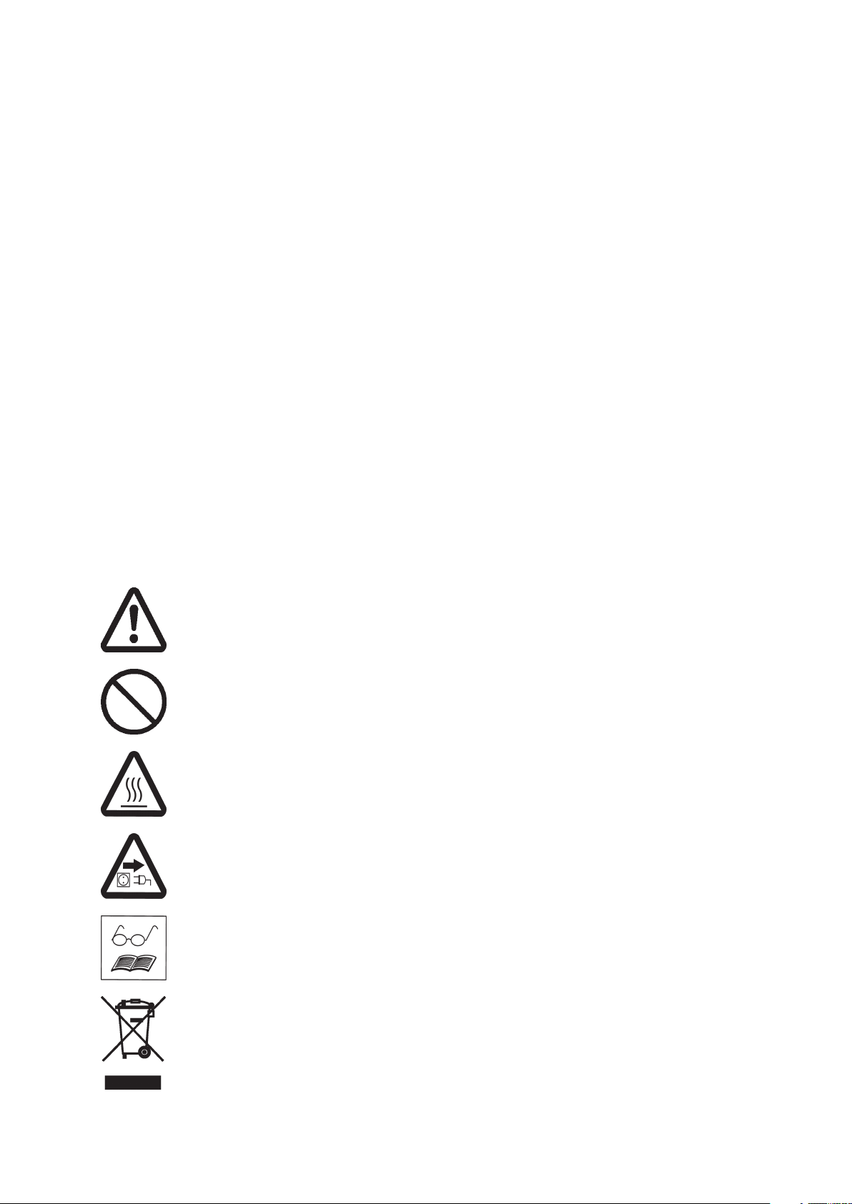
Attention! Important notes!
Not permitted! Misuse may cause damage.
Caution! Hot surface!
Isolate equipment from mains.
Note.
Documents are only to be used and distributed completely and unchanged. It is strictly the users´ responsibility to check
carefully the validity of this document with respect to his product. manual-no.: 997835 / 15/12/2009
Safety information!
Remove all packing material, remove the product from its packing-box, remove the
protective covers and keep, inspect the equipment.
If the equipment is damaged, notify the supplier and the carrier in writing within three
days; state the item number of the product together with the order number and the
supplier’s invoice number. Retain all packing material for inspection.
Do not use the equipment if it is damaged.
If the equipment is not used immediately, replace the protective covers. Store the
equipment in suitable conditions.
☞ Read and obey this manual before installing or operating the equipment.
Use the equipment for the intended use only (for measurement and control of vacuum).
Operate the controller only in combination with VACUUBRAND genuine accessories (e.
g. isolation valve, vacuum management module VMS A). Make sure that the individual
components are only connected, combined and operated according to their design and
as indicated in the instructions for use.
☞ Obey notes on correct vacuum and electrical connections, see section ”Use and
operation”.
☞ Make sure that the individual components are only connected, combined and oper-
ated according to their design and as indicated in the instructions for use.
page 4 of 36
Obey national safety regulations and safety requirements concerning the use of
vacuum and electrical equipment.
☞ Equipment must be connected only to a suitable fused and protected electrical
supply and a suitable earth point. Failure to connect the device to ground may result
in deadly electrical shock.
☞ The supply cable may be fitted with a moulded European IEC plug or a plug suitable
for your local electrical supply. If the plug has been removed or has to be removed,
the cable will contain wires colour coded as follows: green or green and yellow:
earth; blue or white: neutral; brown or black: live.
☞ Check that mains voltage and current conform with the equipment (see rating plate).
☞ If the equipment is brought from cold environment into a room for operation, allow
the equipment to warm up (pay attention to water condensation on cold surfaces).
☞ Make sure ventilation is adequate if the equipment is installed in a housing or if
ambient temperature is elevated.
☞ The controller is equipped with a short circuit proof transformer with an integrated
overload protection (no fuses).
Obey all relevant safety requirements (regulations and guidelines) and adopt suitable
safety measures.
☞ Max. permitted pressure at the controller: 1.5 bar (absolute).
To the best of our knowledge the equipment is in compliance with the requirements of
the applicable EC-directives and harmonized standards with regard to design, type and
model, especially directive IEC 1010. This directive gives in detail conditions, under
which the equipment can be operated safely (see also IP degree of protection).
☞ Adopt suitable measures in case of differences, e. g. using the equipment outdoors,
installation in altitudes of more than 1000 m above mean sea level, conductive
pollution or dewiness.
Do not permit any uncontrolled pressurizing (e. g. make sure that system pipelines
cannot become blocked).
☞ Avoid overpressure of more than 0.2 bar in case inert gas is connected.
Documents are only to be used and distributed completely and unchanged. It is strictly the users´ responsibility to check
carefully the validity of this document with respect to his product. manual-no.: 997835 / 15/12/2009
page 5 of 36
Adopt suitable measures to prevent dangers arising from dangerous or explosive
gases and dangers arising from the formation of explosive fluids or explosive or
flammable mixtures and ensure that the materials of the wetted parts are compatible,
see section “Technical data”.
☞ Adopt suitable measures to prevent the release of dangerous, explosive, corrosive
or polluting fluids.
☞ Use inert gas for venting if necessary.
☞ Take adequate precautions to protect people from the effects of dangerous sub-
stances, wear appropriate safety-clothing and safety glasses.
☞ Position the device in the vacuum system so as to avoid flow of condensate to-
wards the pressure transducer inside the device.
Electronic equipment is never 100% fail-safe. This may lead to an indefinite status of
the equipment. Provide protective measures against malfunction and failure.
☞ Operating the isolation or cooling water valve or the pump (in combination with VMS
Module A) must not lead to a critical dangerous situation under any circumstances.
Use only genuine spare parts and accessories.
☞ Otherwise safety and performance of the equipment as well as the electromagnetic
compatibility of the equipment might be reduced.
Ensure that maintenance is done only by suitably trained and supervised technicians.
Ensure that the maintenance technician is familiar with the safety procedures which
relate to the product processed by the vacuum system and that the equipment, if
necessary, is appropriately decontaminated before starting maintenance.
Obey local and national safety regulations.
Before starting maintenance vent the system, isolate the components from the vacuum
system and the electrical supply.
Before starting maintenance, wait two minutes after isolating the equipment from mains
to allow the capacitors to discharge.
In order to comply with law (occupational, health and safety regulations, safety at work
law and regulations for environmental protection) vacuum pumps, components and
measuring instruments returned to the manufacturer can be repaired only when certain
procedures (see section ”Notes on return to the factory”) are followed.
Documents are only to be used and distributed completely and unchanged. It is strictly the users´ responsibility to check
carefully the validity of this document with respect to his product. manual-no.: 997835 / 15/12/2009

Technical data
page 6 of 36
rellortnoC 2CVC
recudsnarterusserP erusserpetulosbaevitsiserozeipdetargetni
yalpsiD ya
)neewtebdehctiwsebot(elacs/stinuerusserPaPhrorroT,rabm
egnargnirusaeM )rroT1-rro
)etulosba(egnarlortnoC )rroT1-rroT597(rabm1-rabm0601
ruccA
)noitairav
s(ylppussniaM zH06-05/%51-/+~V011
)erutarepmettnatsnoc
tneiciffeocerutarepmeT )K/rroT51.0(K/rabm2.0-/+<
oteud(tfihsorezmretgnoL
)etalpgnitaree
tadnatnemtsujdaluferacretfa(yca
erutarepmet
aidemsuoesagfoerutarepmet.xaM C°08otpusdioreptrohsrof
)noitarepo(egnarerutarepmettneibmAC°04+otC°0+
)egarots(egnarerutarepmettneibmAC°07+otC°01-
II
)rroT5.1(rabm2-/+<
)rroT3(rabm4-/+<
zH06-05/%01-/+~V032
ngisednoisorrocitnahtiw,recudsnart
lpsidDCLlatigiddnagolana
T579(rabm1-rabm0031
925CEInoitcetorpfoeergeD02PI
wardrewoPAV31.xam
ngised)rotcennocelam(tuorewoP
thtiw
evlavecnattimdariA elzzonesoh
noitcennocmuucaV -6htiwsesohmuucavrofelzzonesohd
ssaMgk5.1
)HxWxL(snoisnemiD mm19xmm231xmm142
)dedulcni(gnitnuomdnatS 8Mdaerht,"2/1
rofdeta
)noitcennoclellarap(noitareposuoenatlumis
:seirosseccalanigirogniwollofeh
stnenopmoC strapdetteW
noitcennocmuucaVleetssselniats,SPP
laeSMPF
ebutgnitcennocrosneSCVP
gnisuohrosneS redlosnit-dlog,yolla-nori-l
rosneSnocilis,dloG
=V42evlavretaw-
C51VVroC6VVevlavnoitalosi-
ASMVmetsyStnemeganaMmuucaV-
htiw,detargetni,citengamortkele
)Ømm5(ylppussagtrenirof
eppets
retemaidedisnimm01
Ø,dorniwercs
ekciN
We reserve the right for technical modification without prior note!
Documents are only to be used and distributed completely and unchanged. It is strictly the users´ responsibility to check
carefully the validity of this document with respect to his product. manual-no.: 997835 / 15/12/2009
Description
Operating the controller is possible in four different basic setups, see ”Changing the
basic setup”.
The status of the controller respectively of the connected accessories is displayed by
corresponding symbols on the LCD. After switching on the controller, the version of
the software is displayed, then the preselected basic setup. The solenoid operated
isolation valve is switched if connected (automatic identification), the cooling water
valve is switched, if the valve is configurated.
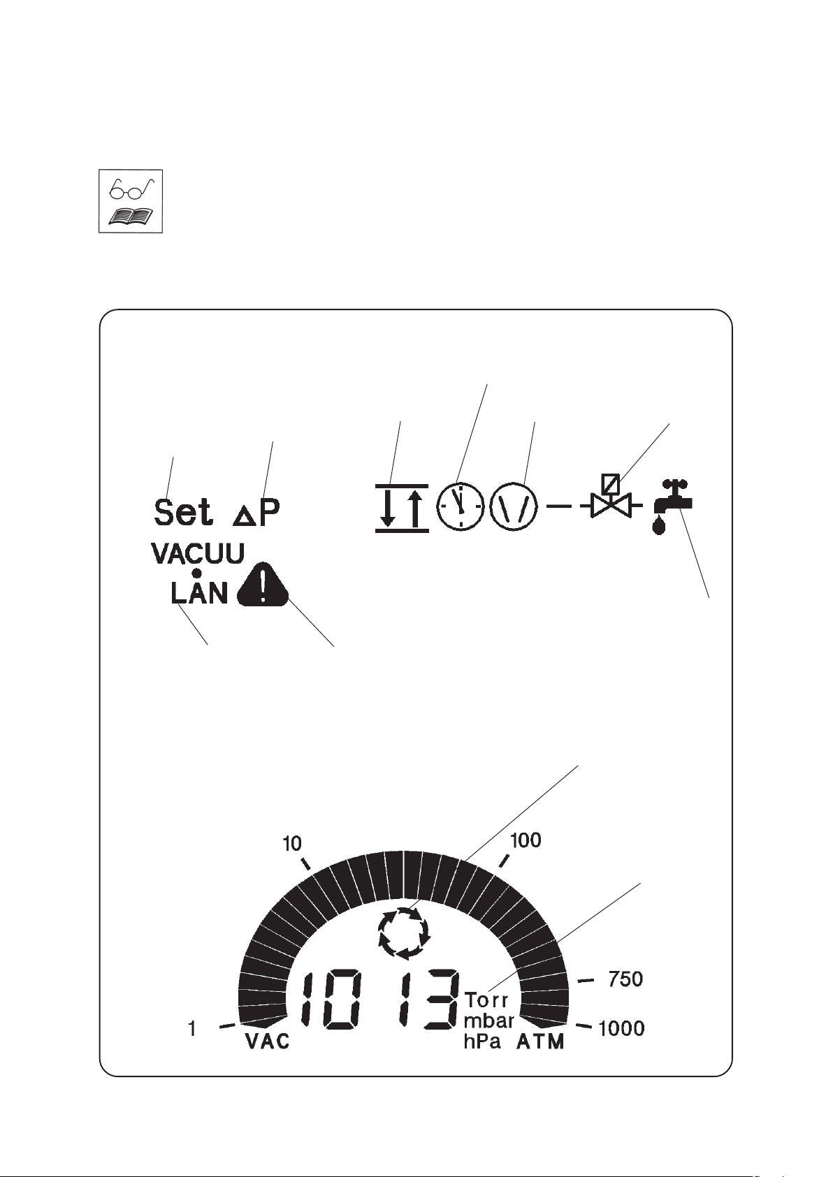
Display
page 7 of 36
countdown till switch off
or hysteresis
settings
basic setup
VACUU•LAN
Pressure reading
warning symbol
(in combination with other symbols)
pump symbolpressure controlsetting pressure
process control
active
isolation valve
cooling water valve
selectable
pressure units
Documents are only to be used and distributed completely and unchanged. It is strictly the users´ responsibility to check
carefully the validity of this document with respect to his product. manual-no.: 997835 / 15/12/2009
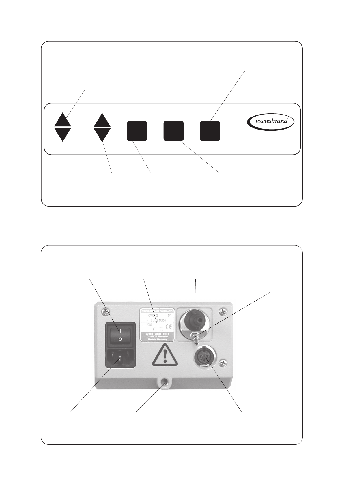
Keys
- setting of set point p
- switching in programs
page 8 of 36
- switching between two-switch-point control and continuous pumping
- special function (in combination with an additional key)
ΔΔ
Δ p
p
setting of hysteresis Δp or
time t for switch-off
ΔΔ
Rear side
mains switch
VENT
operating the built
in air admittance
valve
rating plate vacuum connection
START
STOP
MODE
- start or stop of process control
- confirmation of selected values
CVC 2
air admittance valve:
air inlet/inert gas
connection
II
male connector for
mains cable
Documents are only to be used and distributed completely and unchanged. It is strictly the users´ responsibility to check
carefully the validity of this document with respect to his product. manual-no.: 997835 / 15/12/2009
thread M8 for stand rod
(included)
female connector to connect valves and vacuum
management system VMS Module A
(use Y-socket-plug connector if necessary)
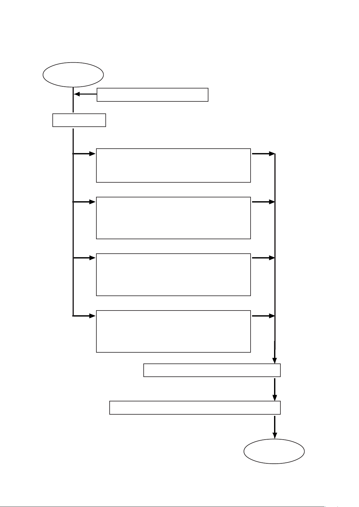
page 9 of 36
General view basic setups
CVC 2
setting basic setup
II
basic setup ”Management”*
controller switches
- pump
- solenoid operated isolation valve if connected
- cooling water valve (optional)
setting pressure unit (mbar / Torr / hPa)
basic setup ”Standard”
controller switches
- solenoid operated isolation valve (indispensable)
- cooling water valve (optional)
(factory-set)
basic setup ”Management
controller switches
- pump, but with after-running to pump out condensate
- solenoid operated isolation valve (indispensable)
- cooling water valve (optional)
basic setup ”VACUU•LAN”*
controller switches
- pump according to preset pressure and time
values
- solenoid operated isolation valve if connected
configuration of the cooling water valve if applicable
automatic identification of the solenoid operated isolation valve
Plus”
*
* only in combination with Vacuum-ManagementSystem VMS Module A
ready to
start
Documents are only to be used and distributed completely and unchanged. It is strictly the users´ responsibility to check
carefully the validity of this document with respect to his product. manual-no.: 997835 / 15/12/2009

page 10 of 36
How to work with the controller
How to change the pressure units
Press key p▲ or p▼ while switching on.
mbar
+
p
(mains switch)
Setting the cooling water valve (optional)
The controller switches a preselected cooling water valve.
A cooling water valve has to be configurated at the controller before starting the process see section
”Changing the basic setup”.
Torr
hPa
☞ The pressure units are displayed, the pressure unit as from
last operation is flashing.
➨ Press key p▲ or p▼ to change pressure unit. Press key
START/STOP to confirm and to finish the operation mode.
It is possible to configurate the cooling water valve in all basic setups, see scheme above.
Documents are only to be used and distributed completely and unchanged. It is strictly the users´ responsibility to check
carefully the validity of this document with respect to his product. manual-no.: 997835 / 15/12/2009
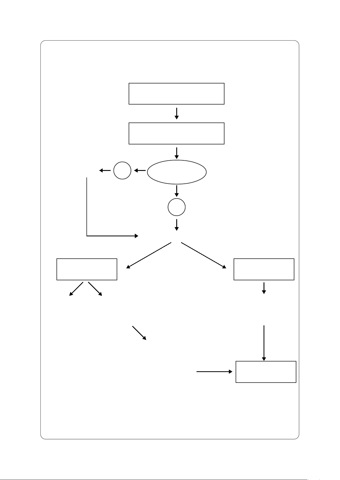
page 11 of 36
General view basic setup ”Standard”
setting the basic setup
basic setup Standard
configurate
cooling water valve
continuous
pumping
pumping
down to ulti-
mate vacuum
of the pump
yes
setting the operation mode
semiautomatic
determination of
the boiling point
switching cooling
water valve?
no
two-point control
manual setting:
set point (boiling point)
and hysteresis
switching to two-point control:
actual pressure is stored as
new set point
Documents are only to be used and distributed completely and unchanged. It is strictly the users´ responsibility to check
carefully the validity of this document with respect to his product. manual-no.: 997835 / 15/12/2009
process control
 Loading...