

Page 1

V2 S.p.A.
Corso Principi di Piemonte, 65/67
12035 RACCONIGI (CN) ITALY
tel. +39 01 72 81 24 11 - fax +39 01 72 84 050
info@v2home.com - www.v2home.com
WES-SENSOR
L n. 342
I
DIZ. 01/03/2011
E
I
GB
F
E
P
D
SISTEMA PER IL CONTROLLO VIA RADIO DELLE
COSTE DI SICUREZZA
RADIO CONTROL SYSTEM FOR SAFETY EDGES
SYSTÈME POUR LE CONTRÔLE PAR RADIO DES
BARRES PALPEUSES DE SÉCURITÉ
SISTEMA PARA EL CONTROL VÍA RADIO DE LAS
BANDAS DE SEGURIDAD
SISTEMA PARA O CONTROLO VIA RÁDIO DAS
COSTAS DE SEGURANÇA
FUNK-STEUERSYSTEM FÜR SICHERHEITSRIPPEN
NL
SYSTEEM VOOR DE CONTROLE VAN
VEILIGHEIDSLIJSTEN VIA RADIO
Page 2
Page 3

AVVERTENZE IMPORTANTI
Per chiarimenti tecnici o problemi di installazione contatta il
Servizio Clienti V2 al Numero Verde 800-134908 attivo dal lunedì
al venerdì dalle 8:30 alle 12:30 e dalle 14:00 alle 18:00
V2 si riserva il diritto di apportare eventuali modifiche al
prodotto senza preavviso; inoltre declina ogni
responsabilità per danni a persone o cose dovuti ad un uso
improprio o ad un’errata installazione.
Leggere attentamente il seguente manuale di
istruzioni prima di procedere con l'installazione e la
programmazione del sistema.
• Il presente manuale di istruzioni è destinato solamente a
personale tecnico qualificato nel campo delle installazioni di
automazioni.
• Nessuna delle informazioni contenute all'interno del manuale
può essere interessante o utile per l'utilizzatore finale.
• Qualsiasi operazione di manutenzione o di programmazione
deve essere eseguita esclusivamente da personale qualificato.
L’installazione, il collaudo e la messa in servizio delle automazioni
per porte e cancelli deve essere eseguita da personale qualificato
ed esperto che dovrà farsi carico di stabilire le prove previste in
funzione dei rischi presenti e di verificare il rispetto di quanto
previsto da leggi, normative e regolamenti.
• V2 non risponde dei danni risultanti da un uso improprio del
prodotto diverso da quanto previsto nel presente manuale.
• Il materiale dell'imballaggio deve essere smaltito nel pieno
rispetto della normativa locale.
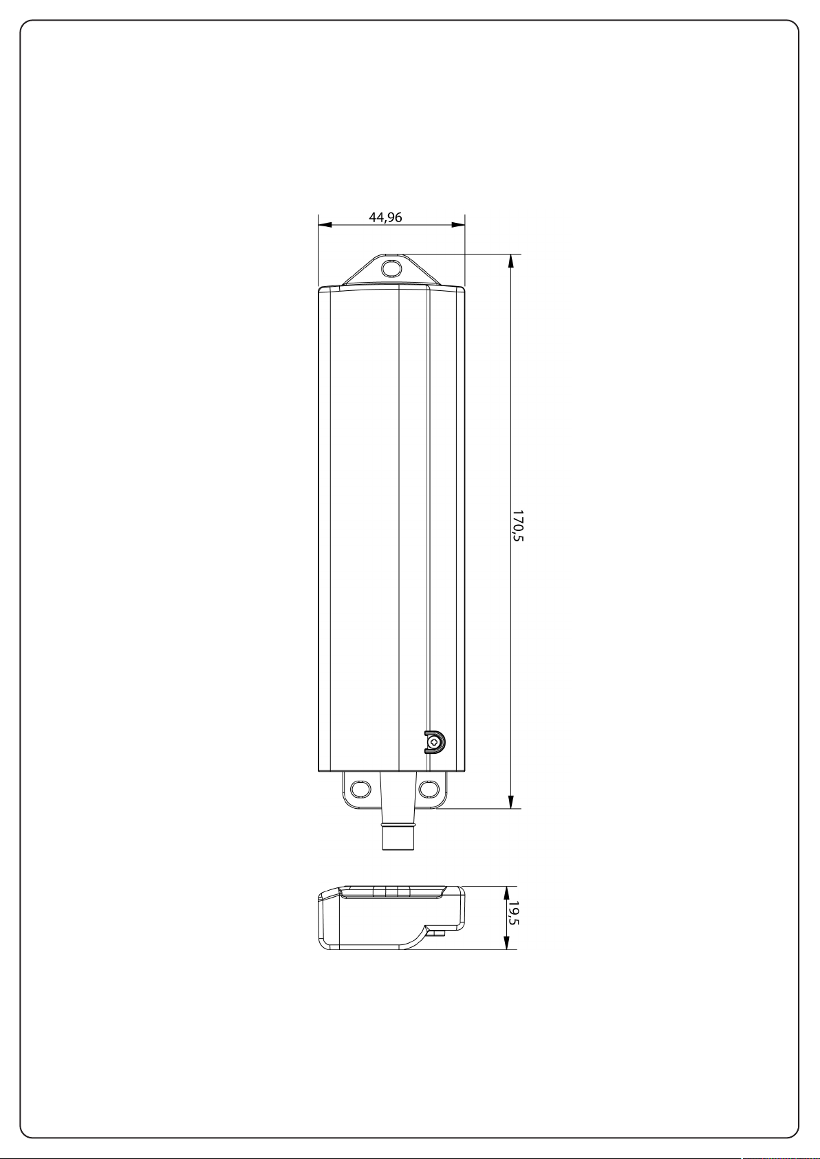
DATI TECNICI
Sensore
Alimentazione: 2 batterie LR6/AA (1,5V-2600mAh)
Autonomia in stand by: > 2 anni
Dimensioni: 170,5x45x19,5 mm
emperatura di lavoro:-15/+50 °C
T
Ingressi: 2 coste meccaniche o resistive
Portata massima: 10 m
DESCRIZIONE
WES (Wireless Edge System) è il nuovo sistema V2 che permette
di controllare le coste di sicurezza via radio.
Il sistema è composto da una base collegata direttamente alla
centrale di comando e da uno o più sensori (fino a 8 per base)
collegati alle coste di sicurezza.
La base viene alimentata dalla centrale di comando e verifica
costantemente lo stato dei sensori che sono connessi.
Ad ogni base si possono connettere fino ad un massimo di 8
sensori.
Il sistema è compatibile con coste di sicurezza tradizionali con
contatto N.C. , coste di sicurezza resistive (8k2).
Il sistema è compatibile con qualunque centrale di comando
.
ITALIANO
DICHIARAZIONE DI CONFORMITÀ
Il sottoscritto rappresentante il seguente costruttore:
V2 S.p.A.
Racconigi - Corso Principi di Piemonte 65 (CN) - ITALY
dichiara qui di seguito che il prodotto WES
risulta in conformità a quanto previsto dalle seguenti direttive
comunitarie (comprese tutte le modifiche applicabili)
99/5/CE - Direttiva riguardante le apparecchiature radio e le
apparecchiature terminali di telecomunicazione e il reciproco
riconoscimento della loro conformità
98/37/CE - concernente il ravvicinamento delle legislazioni degli
Stati membri relative alle macchine
e che sono state applicate le norme tecniche sotto indicate:
EN 301 489-3: 2002 - Compatibilità elettromagnetica e questioni
relative allo spettro delle radiofrequenze (ERM); norma di
compatibilità elettromagnetica (EMC) per apparecchiature e
servizi radio.
Parte 3:Condizioni specifiche per dispositivi a breve portata (SRD)
operanti su frequenze tra 9 kHz e 40 GHz.
EN 300 328-1: 2001 - Compatibilità elettromagnetica e spettro
radio (ERM); Sistemi di trasmissione a banda larga. Apparati di
trasmissione dati operanti nella banda ISM a 2.4GHz usando
tecniche di modulazione a spettro espanso.
Funzionamento del sistema
Il sistema funziona in modo indipendente dallo stato della
centrale. Il relè corrispondente a ciascun gruppo di sensori viene
tenuto chiuso se nessuna costa viene attivata.
Se una costa viene premuta il relè si apre segnalando l’anomalia
alla centrale.
Ogni 15 secondi la base comunica con ciascun sensore, in modo
da rilevarne la presenza e la funzionalità.
EN 12978 : 2003 - Porte e cancelli industriali, commerciali e da
garage - Dispositivi di sicurezza per porte e cancelli motorizzati Requisiti e metodi di prova
Racconigi il 12/10/2009
Rappresentante legale V2 S.p.A.
Cosimo De Falco
1
Page 4
ITALIANO
SCHEMA DI INSTALLAZIONE
NOTA: per garantire il funzionamento ottimale del sistema
è importante che la distanza tra i sensori e la base sia
minima e non superi mai la distanza massima consentita.
Inoltre è importante evitare il collocamento di superfici
metalliche tra base e sensore.
INSTALLAZIONE DEI SENSORI
ATTENZIONE: l’installazione dei sensori deve
essere fatta con il sistema in funzione e quindi con la
centrale accesa: assicurarsi che l’automazione non possa
iniziare una manovra mentre si sta effettuando
l’installazione.
In caso di installazioni all’aperto, il sensore deve
obbligatoriamente essere montato in posizione verticale,
con l’uscita dei cavi verso il basso.
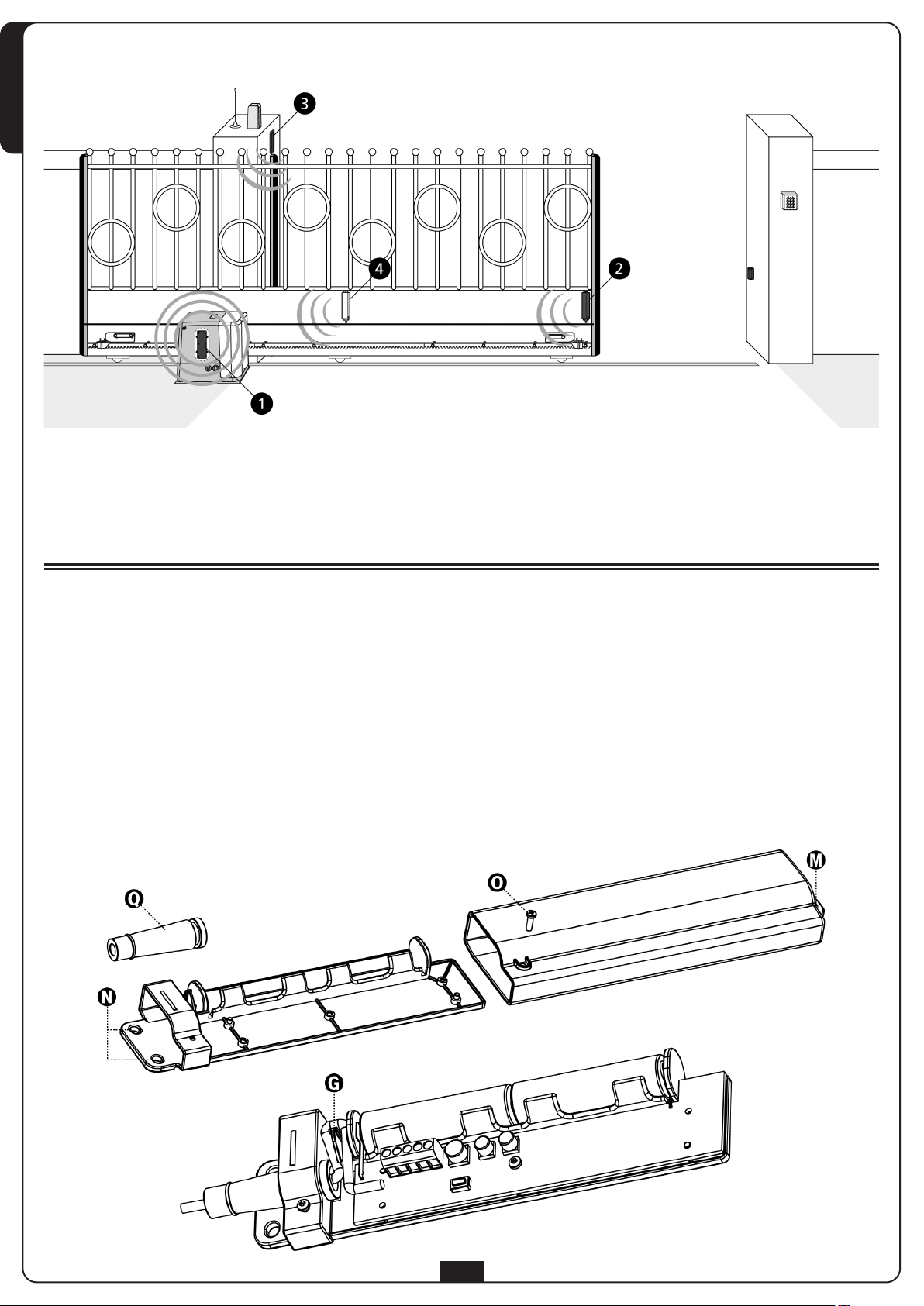
1. Usare l’occhiello M sul coperchio e i due occhielli N sulla base
per fissare il sensore.
1 Base WES (installata all’interno del motore)
2 Sensore WES che controlla 2 coste
3 Sensore WES
4 Sensore WES: posizione consigliata per cancelli di grandi
dimensioni
2. Per aprire il contenitore, liberare indifferentemente il
coperchio svitando la vite sull’occhiello M, o la base svitando
le viti sugli occhielli N, quindi svitare la vite O che unisce le
due parti e aprire il contenitore.
3. Rimuovere il gommino passacavo Q; far passare i fili di
collegamento della costa o delle coste attraverso il foro sulla
base e quindi nel gommino.
4. Far passare i fili attraverso la gola anti-sfilamento G e
collegarli nei morsetti.
5. Inserire la parte stretta del gommino nel foro e tirare
dall’esterno finché il gommino non scatta in posizione.
2
Page 5
COLLEGAMENTI ELETTRICI DEL
SENSORE
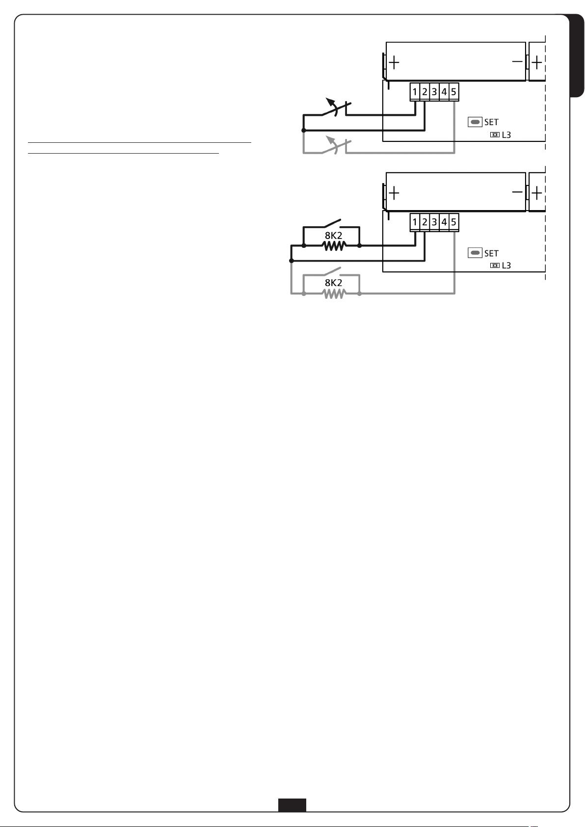
Coste meccaniche o resistive
Collegare i fili della costa tra i morsetti 1 e 2.
Opzionalmente, una seconda costa dello stesso tipo può essere
collegata tra i morsetti 2 e 5.
Se la prima costa viene associata al gruppo 1, la seconda si
assocerà automaticamente al gruppo 2 e viceversa.
E’ anche possibile collegare in cascata più coste: in questo caso
verranno associate tutte allo stesso gruppo.
NOTA: se la centrale di comando ha solo un ingresso per le
coste collegare le coste in cascata e associarle tutte al
GRUPPO1.
ITALIANO
ASSOCIAZIONE CON LA BASE
Durante la fase di associazione il sensore comunica alla base la configurazione con cui è stato installato.
NOTA: se un sensore non è collegato a nessuna costa non può essere associato alla base.
ATTENZIONE: prima di procedere assicurarsi di aver collegato le coste ai sensori in modo corretto.
Quando l’associazione viene terminata non è più possibile modificare i collegamenti del sensore.
Inserire le batterie rispettando la polarità: polo positivo verso il passaggio cavi (contatto a lamella) e polo negativo verso l’antenna (contatto
a molla). Verificare che nei primi secondi il led lampeggi debolmente. Se il led emette lampeggi intensi vuol dire che il sensore è già stato
configurato; è necessario cancellare la vecchia configurazione (vedi paragrafo RESET CONFIGURAZIONE DEL SENSORE)
Per associare una costa al gruppo 1 procedere come segue:
1. Premere 1 volta il tasto PROG della base: il led ALARM emette dei lampeggi singoli
2. Tenere premuto il tasto SET del sensore finché il led L3 non emette lampeggi intensi e regolari, quindi rilasciare il tasto.
3. La base esce automaticamente dalla modalità di apprendimento e il sensore inizia a trasmettere con un periodo di 15 secondi
Per associare una costa al gruppo 2 procedere come segue:
1. Premere 2 volte il tasto PROG della base: il led ALARM emette dei lampeggi doppi
2. Tenere premuto il tasto SET del sensore finché il led L3 non emette lampeggi intensi e regolari, quindi rilasciare il tasto.
3. La base esce automaticamente dalla modalità di apprendimento e il sensore inizia a trasmettere con un periodo di 15 secondi
Per associare una costa a entrambi i gruppi procedere come segue:
1. Premere 3 volte il tasto PROG della base: il led ALARM emette dei lampeggi tripli
2. Tenere premuto il tasto SET del sensore finché il led L3 non emette lampeggi intensi e regolari, quindi rilasciare il tasto.
3. La base esce automaticamente dalla modalità di apprendimento e il sensore inizia a trasmettere con un periodo di 15 secondi
NOTA: L’associazione deve essere completata entro 15 secondi, altrimenti la base esce dalla modalità di apprendimento.
4. Al termine, richiudere il contenitore del sensore e fissare nuovamente le viti.
5. Ripetere l’operazione per gli altri sensori della rete. Quando tutti i sensori sono stati installati e associati, chiudere anche il
coperchio della base.
3
Page 6

RESET CONFIGURAZIONE DEL SENSORE
Per cancellare la configurazione di un sensore è necessario tenere premuto il tasto SET del sensore fino a quando il led non rimane acceso.
Quindi rilasciare il tasto e ripetere la configurazione del canale radio.
ITALIANO
TEST DELLA COSTA
ttivare la modalità di test sulla base, spostando il dip switch 8 su ON. Premere la costa e verificare che:
A
1. Il led sul sensore rimanga acceso fisso
2. Il led rosso (OUT1/OUT2) sulla base si accenda
3. La centrale riconosca l’allarme sull’ingresso a cui è collegata l’uscita relativa al gruppo
ATTENZIONE: Terminato il test, ricordarsi di riportare il dip switch 8 su OFF.
SOSTITUZIONE DELLE BATTERIE
Quando le batterie sono cariche ogni trasmissione del sensore viene visualizzata con un lampeggio del led L3.
Quando le batterie sono quasi scariche il lampeggio di L3 è più lungo.
Quando le batterie sono troppo scariche, il sensore lo segnala alla base che apre il relè collegato all’uscita BAT LOW e accende il led
relativo.
La sostituzione delle batterie può avvenire senza spegnere il sistema. Procedere come segue
1. Togliere la vite O che fissa il coperchio alla base.
2. Togliere la vite M che tiene fermo il coperchio e farlo scorrere sulla base
3. Rimuovere le batterie e inserire le nuove rispettando la polarità (UTILIZZARE SOLO BATTERIE MODELLO LR6/AA 1,5V-2600mAh)
4. Richiudere il contenitore e fissarlo nuovamente.
:
PROCEDURA DI RICERCA GUASTO
Eseguire la ricerca guasto con il sistema spento (porta ferma).
STEP Azione Verifica Diagnosi
1.
2. Il led ALARM è acceso fisso?
3.
4. Osservare il led di un sensore Il led è acceso fisso?
Aprire il coperchio della base e
osservare il led rosso
Mettere il dip switch 8 su ON: il led
ALARM inizialmente si accende
Il led LOW BAT è acceso?
I tre led OUT1, OUT2 e BAT LOW
sono spenti?
Un sensore ha la batteria scarica; cercare il
sensore il cui led lampeggia
Problemi di comunicazione tra sensori e base.
Cercare un sensore il cui led è spento o emette
lampeggi molto deboli
Il sistema funziona regolarmente. Se la centrale
non segnala che l’ingresso costa si è chiuso c’è
un problema di collegamento (filo interrotto)
Il sensore rileva che la costa è stata azionata;
problema di collegamento o guasto della costa
5. Azionare la costa Il led sul sensore non si accende?
6. -
7.
Ripetere i passi 4, 5 e 6 per ogni
sensore
La centrale segnala che l’ingresso
costa è chiuso?
Tutti i sensori funzionano
regolarmente?
Il sensore non rileva lo stato della costa; problema
di collegamento o guasto della costa
Problemi di collegamento tra centrale e base
(cortocircuito)
Nella rete è inserito un sensore inesistente.
Bisogna cancellare la rete e ripetere
l’assegnazione dei sensori.
ATTENZIONE: Al termine della procedura, ricordarsi di rimettere il dip switch 8 su OFF.
4
Page 7

IMPORTANT INFORMATION
For any installation problem please contact our Customer
Serviceat the number +39-0172.812411 operating Monday to
Fridayfrom 8:30 to 12:30 and from 14:00 to 18:00
V2 reserves the right to make modifications to the product
without any prior warning; furthermore, the company
declines all responsibility for damages to people or property
resulting from improper use or incorrect installation.
Read the following instruction manual thoroughly
prior to proceeding with installation and programming of
the system.
• This instruction manual is intended solely for use by technical
staff, qualified in the field of installation of automation devices
• None of the information contained in the manual is of interest
or use to end users.
• All maintenance or programming operations should be
conducted exclusively by qualified staff.
The installation, testing and commissioning of door and gate
automation devices should be performed by qualified and skilled
personnel, who must assume responsibility for setting up the
tests envisaged depending on the risks present; and verify
compliance in accordance with legal and regulatory requirements.
• V2 accepts no responsibility for injuries and damage resulting
from improper use of the product; other than that described in
this manual.
• Packing materials must be disposed of in full compliance with
local regulations.
TECHNICAL INFORMATION
Sensor
Power supply: 2 LR6/AA batteries (1.5 V-2600 mAh)
Stand-by time: >2 years
Dimensions: 170,5x45x19,5 mm
Operating temperature: -15/+50 °C
Inputs: 2 mechanical or resistive edges
Maximum range: 10 m
DESCRIPTION
WES (Wireless Edge System) is the new V2 system allowing safety
edges to be controlled by radio.
The system consists of a base unit connected directly to the
control unit, and one or more sensors (up to 8 per base unit)
connected to the safety edges.
The base unit is powered from the control unit and constantly
monitors the status of the sensors connected.
Up to a maximum of 8 sensors may be connected to each base
unit.
The system is compatible with standard safety edges with NC
breakers, resistive safety edges (8k2).
The system is compatible with all control unit models
.
ENGLISH
DECLARATION OF CONFORMITY
The undersigned representing the following manufacturer:
V2 S.p.A.
Corso Principi di Piemonte 65, Racconigi (CN), ITALY
herein declares that the product WES
is in compliance with the provisions of the following community
directives (including all applicable amendments)
99/5/CE
Directive regarding radio equipment and telecommunication
terminal equipment and reciprocal recognition of their conformity
98/37/CE
concerning the harmonisation of legislation from member states
regarding machinery
and that the technical standards indicated below have been applied:
EN 301 489-3: 2002
Electromagnetic compatibility and questions relating to the
radiofrequency spectrum (ERM); electromagnetic compatibility
(EMC) standards for radio equipment and services.
Part 3: specific conditions for short range devices (SRD) operating
between the frequencies of 9 kHz and 40 GHz.
EN 300,328-1: 2001
Electromagnetic and radio spectrum compatibility (ERM);
Broadband transmission systems. Data transmission equipment
operating in the ISM band at 2.4 GHz using broad spectrum
modulation techniques.
System operation
The system operates independently of the status of the control
unit. The relay corresponding to each sensor unit is kept closed if
no edges are activated.
If an edge is pressed, the relay opens, signalling the anomaly to
the control unit.
The base unit communicates with each sensor every 15 seconds,
so as to verify their presence and function.
EN 12978 : 2003
Industrial, commercial and garage doors and gates - Safety devices
for motorised doors and gates - Test methods and requirements
Racconigi, 12/10/2009
V2 S.p.A. Legal Representative
Cosimo De Falco
5
Page 8

INSTALLATION LAYOUT
ENGLISH
NOTE: in order to guarantee optimal system operation, it is
important that the distance between the sensors and the
base be as short as possible and never exceed the
maximum permitted distance.
In addition, it is important to avoid positioning metal
surfaces between the base and sensors.
SENSOR INSTALLATION
WARNING: Sensors should be installed with the
system in operation, hence with the control unit on: make
sure the automation device cannot start a manoeuvre
during installation.
In the case of open air installations, the sensor must be
fitted vertically, with the cable outlet facing downwards.
1. Use fixing lug M on the cover and the two fixing lugs N on
the base to fix the sensor.
1 WES base (installed inside the motor)
2 WES sensor controlling 2 edges
3 WES sensor
4 WES sensor: recommended position for large gates
2. To open the casing, loosen either the cover by unscrewing the
screw in lug M, or the base by unscrewing the screws in lugs
N, then unscrew screw O which joins both parts of the
casing.
3. Remove the grommet Q; pass the edge connecting wires
through the hole in the base and then through the grommet.
4. Pass the wires through the anti-slip channel G and connect
them to the terminals.
5. Insert the narrow end of the grommet in the hole and pull
outwards so that the grommet snaps into position.
6
Page 9
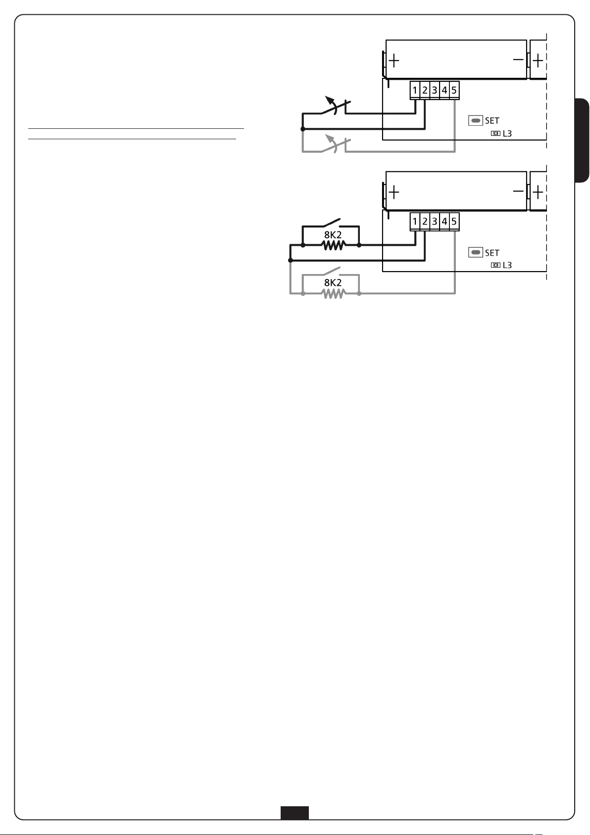
SENSOR ELECTRICAL CONNECTIONS
Mechanical or resistive edges
Connect the edge wires to terminals 1 and 2.
Optionally, a second edge of the same type may be connected to
terminals 2 and 5.
If the first edge is associated with unit 1, the second will
automatically be associated with unit 2, and vice versa.
It is also possible to connect several edges in cascade: in this case,
they will all be associated with the same unit.
PLEASE NOTE: if the control unit has only one edge input,
connect the edges in cascade and associate them all with
UNIT 1.
ENGLISH
ASSOCIATION WITH THE BASE UNIT
During association, the sensor communicates the installed configuration to the base.
NOTE: if a sensor is not connected to any edge, it cannot be associated with a base.
CAUTION: make sure edges are connected properly to the sensors prior to proceeding.
When association is complete, it is no longer possible to alter the sensor connections.
Insert the batteries taking care to observe the polarity: Positive pole towards the cable track (plate contact) and the negative pole towards
the antenna (spring contact). Ensure the LED flashes faintly in the first seconds. If the LED flashes intensely, this means the sensor has
already been configured; it is necessary to delete the old configuration (see the RESET SENSOR CONFIGURATION section)
To associate an edge with unit 1, proceed as follows:
1. Press the PROG button on the base unit once: the ALARM LED emits single flashes
2. Press and hold the sensor SET button until LED L3 flashes intensely and regularly, then release the button.
3. The base automatically exits acquisition mode and the sensor starts to transmit with a period of 15 seconds
To associate an edge with unit 2, proceed as follows:
1. Press the PROG button on the base unit twice: the ALARM LED emits dual flashes
2. Press and hold the sensor SET button until LED L3 flashes intensely and regularly, then release the button.
3. The base automatically exits acquisition mode and the sensor starts to transmit with a period of 15 seconds
To associate an edge with both units, proceed as follows:
1. Press the PROG button on the base unit 3 times: the ALARM LED emits triple flashes
2. Press and hold the sensor SET button until LED L3 flashes intensely and regularly, then release the button.
3. The base automatically exits acquisition mode and the sensor starts to transmit with a period of 15 seconds
PLEASE NOTE: Association must be completed within 15 seconds, otherwise the base unit exits acquisition mode.
4. On completion, close the sensor casing and tighten the screws once more.
5. Repeat the operation for the other sensors in the network. When all the sensors have been installed and associated,
close the base unit casing.
7
Page 10

RESET SENSOR CONFIGURATION
To delete the configuration of a sensor, it is necessary to press and hold the SET button on the sensor until the LED remains on.
Then release the button and repeat the radio channel configuration.
EDGE TESTING
ctivate the base unit testing method by setting dip-switch 8 to ON. Press the edge to verify that:
A
1. the LED on the sensor remains fixed and on
2. the red (OUT1/OUT2) LED on the base unit comes on
3. The control unit recognises the alarm on the input where the output from the u
ENGLISH
PLEASE NOTE: Remember to return dip-switch 8 to OFF on completion of the test.
REPLACING THE BATTERIES
When the batteries are charged, each transmission from the sensor is displayed by LED L3 flashing.
When the batteries are almost run down, LED L3 flashes for longer periods of time.
When the batteries are too low, the sensor signals this to the base which opens the relay connected to the LOW BAT output and switches
on the relevant LED.
The batteries may be replaced without switching the system off. Proceed as follows
1. Remove the screw O fixing the cover to the base.
2. Remove the screw M holding the cover and slide it off the base
3. Remove the batteries and insert new ones, observing the polarity (ONLY USE MODEL LR6/AA BATTERIES – 1.5 V – 2600 mAh)
4. Reclose the casing and fix it once more.
:
FAULT FINDING PROCEDURE
Conduct fault-finding with the system off (door closed).
STEP Action Test Diagnosis
1.
2. Is the ALARM LED on and fixed?
3.
4. Observe the LED for a sensor Is the LED on and fixed?
Open the base cover and observe
the red LED
Set dip switch 8 to ON:
the ALARM LED initially comes on
Is the LOW BAT LED on?
Are the three leds OUT1, OUT2 and
BAT LOW off?
A sensor has a low battery; find the sensor with
the flashing LED
Communication problems between the sensors
and the base. Find the sensor with the LED off or
flashing very faintly
The system is operating normally. If the control
unit does not show that the edge input has been
closed, there is a connection problem (broken
wire)
The sensor detects that the edge has been
activated; connection problem or faulty edge
5. Operate the edge
6. -
7.
Repeat steps 4, 5 and 6 for each
sensor
Does the LED on the sensor come
on?
Does the control unit indicate the
edge input is closed?
Are all sensors operating normally?
The sensor does not detect the status of the
edge; connection problem or faulty edge
Connection problems between the control unit
and the base (short circuit)
A non-existent sensor is included in the network.
It is necessary to delete the network and repeat
assignment of the sensors
PLEASE NOTE: Remember to set dip-switch 8 to OFF on completion of the procedure.
8
Page 11

CONSEILS IMPORTANTS
Pour tout précision technique ou problème d’installation V2 dispose
d’un Service Clients à Votre disposition du lundi au vendredi de 8:30
à 12:30 et de 14:00 heures à 18:00 heures. au
numéro +39-0172.812411
2 se réserve le droit d'apporter d’éventuelles modifications
V
au produit sans préavis; elle décline en outre toute
responsabilité pour tous types de dommages aux personnes ou
aux choses dus à une utilisation impropre ou à une mauvaise
installation.
Lire attentivement le manuel suivant d’instructions avant
de procéder à l’installation et à la programmation du système
• Le présent manuel d'instruction est destiné uniquement à des
techniciens qualifiés dans le domaine des automatismes
• Aucune des informations contenues dans ce manuel ne
pourra être intéressante ou utile à l’utilisateur final
• Toutes les opérations de maintenance ou de programmation
doivent être effectuées exclusivement par un technicien qualifié
L'installation, les essais et la mise en service des automations pour
portes et portails doivent être exécutés par un personnel qualifié et
expert qui devra se charger d'effectuer les tests prévus en fonction
es risques présents et de vérifier la conformité aux dispositions des
d
lois, normes et règlements;
• V2 ne répond pas des dommages résultants d'un usage impropre
du produit, différent de celui prévu dans le présent manuel
• Le matériel d'emballage doit être éliminé conformément à la
norme locale en vigueur en matière de déchets
DÉCLARATION DE CONFORMITÉ
Le représentant pour le compte du constructeur V2 S.p.A.
Racconigi - Corso Principi di Piemonte 65 (CN) - ITALIE
déclare ci-dessous que le produit WES
DONNEES TECHNIQUES
Capteur
Alimentation: 2 batteries LR6/AA (1,5V-2600mAh)
utonomie en stand by:>2 ans
A
Dimensions: 170,5x45x19,5 mm
Température de
fonctionnement:
ntrées:
E
Portée maximum: 10 m
-15/+50 °C
2 barres palpeuses mécaniques ou
résistantes
DESCRIPTION
WES (Wireless Edge System) est le nouveau système V2 qui
permet de contrôler les barres palpeuses de sécurité par radio.
Le système est composé d'une base directement reliée à la
centrale de commande et d'un ou plusieurs capteurs (jusqu'à 8
par base) reliés aux barres palpeuses de sécurité.
La base est alimentée par la centrale de commande et contrôle en
continu le statut des capteurs qui lui sont connectés.
À chaque base, il est possible de relier jusqu’à 8 capteurs.
Le système est compatible avec les barres palpeuses de sécurité
traditionnelles à contact N.C, barres palpeuses de sécurité
résistantes (8k2)
Ce système est compatible avec toutes les armoires de
commande.
FRANÇAIS
est conforme aux dispositions prévues par les directives
communautaires suivantes (y compris toutes les modifications
applicables)
99/5/CE
Directive concernant les appareillages radio et les appareillages de
terminaux de télécommunication et la reconnaissance réciproque
de leur conformité
98/37/CE
concernant le rapprochement des législations des État membres
relatifs aux machines
et que les normes techniques suivantes ont été appliquées
EN 301 489-3: 2002
Compatibilité électromagnétique et problèmes relatifs au spectre
des radiofréquences (ERM); règle de compatibilité
électromagnétique (EMC) pour appareillages et services radio.
Partie 3: Conditions spécifiques concernant les systèmes à courte
portée (SRD) intervenant sur les fréquences comprises entre 9 kHz
et 40 GHz.
EN 300 328-1: 2001
Compatibilité électromagnétique et spectre radio (ERM);
Systèmes de transmission à bande large. Appareils de
transmission de données opérant sur la bande ISM à 2.4GHz en
utilisant les techniques de modulation à spectre étendu.
Fonctionnement du système
Le système fonctionne indépendamment du statut de la centrale.
Le relais correspondant à chaque groupe de capteurs est
maintenu fermé si aucune barre palpeuse n’est activée.
Si une barre palpeuse est enfoncée, le relais s'ouvre en signalant
l'anomalie à la centrale.
Toutes les 15 secondes, la base communique avec chaque
capteur de façon à en détecter la présence et la fonctionnalité.
EN 12978 : 2003
Portes et portails industriels, commerciaux et de garage Dispositifs de sécurité pour portes et portails motorisés - Qualités
et méthodes de preuve
Racconigi le 12/10/2009
Le représentant légal V2 S.p.A.
Cosimo De Falco
9
Page 12

SCHÉMA D’INSTALLATION
FRANÇAIS
REMARQUE: pour garantir le fonctionnement optimal du
système il est important que la distance entre les capteurs
et la base soit minimum et ne dépasse jamais la distance
maximum admissible.
En outre, Il est important d'éviter de placer des surfaces
métalliques entre la base et le capteur.
INSTALLATION DES CAPTEURS
ATTENTION : l'installation des capteurs doit être
effectuée avec le système en marche et donc avec la
centrale allumée: s'assurer que l'automation ne puisse pas
amorcer de manoeuvre lors de l'installation.
En cas d'installations en plein air, le capteur doit
obligatoirement être monté en position verticale, avec la
sortie de câbles vers le bas.
1. Utiliser l’oeillet M situé sur le couvercle et les deux oeillets N
situés sur la base pour fixer le capteur.
1 base WES (installée à l'intérieur du moteur)
2 capteur WES qui contrôle 2 barres palpeuses
3 capteur WES
4 capteur WES: position conseillée pour portails de grandes
dimensions
2. Pour ouvrir le boîtier, libérer indifféremment le couvercle, en
dévissant la vis de l’oeillet M, ou la base en dévissant les vis
sur les oeillets N, puis dévisser la vis O unissant les deux
parties et ouvrir le boîtier.
3. Retirer le petit bouchon en caoutchouc pour le passage du
câble Q; faire passer les fils de raccordement de la barre
palpeuse ou des barres palpeuses à travers le trou situé sur
la base par le caoutchouc.
4. Faire passer les fils à travers le tube anti-extraction G et les
brancher aux bornes.
5. Insérer la partie étroite du petit bouchon en caoutchouc dans
le trou et tirer depuis l'extérieur jusqu’à ce que le petit
bouchon en caoutchouc soit positionné.
10
Page 13

RACCORDEMENTS ÉLECTRIQUES DU
CAPTEUR
Barres palpeuses mécaniques ou résistantes
Relier les fils de la barre palpeuse entre les bornes 1 et 2.
De façon facultative, une seconde barre palpeuse du même type
peut être reliée entre les bornes 2 et 5.
Si la première barre palpeuse est associée au groupe 1, la
seconde s’associera automatiquement au groupe 2 et vice versa.
Il est également possible de réunir en cascade plusieurs barres
palpeuses: dans ce cas, elles seront toutes associées au même
groupe.
REMARQUE: si la centrale de commande possède une seule
entrée pour les barres palpeuses, relier les barres palpeuses
en cascade et les associer toutes au GROUPE1.
FRANÇAIS
ASSOCIATION AVEC LA BASE
Pendant la phase d'association le capteur communique à la base la configuration avec laquelle il a été installé.
REMARQUE: si un capteur n'est relié à aucune barre palpeuse il ne peut pas être associé à la base.
ATTENTION : avant de procéder s'assurer d'avoir relié les barres palpeuses au capteurs de façon correcte.
Quand l'association est terminée il n'est plus possible de modifier les branchements du capteur.
Insérer les batteries en respectant la polarité: pôle positif vers le passage des câbles (contact à lamelle) et pôle négatif vers l'antenne
(contact à ressort). Vérifier que le voyant clignote faiblement durant les premières secondes. Si le voyant clignote de façon intensive, cela
signifie que le capteur a déjà été configuré; il est nécessaire d'effacer l’ancienne configuration (voir paragraphe RESET CONFIGURATION
DU CAPTEUR)
Pour associer une barre palpeuse au groupe 1 suivre la procédure suivante:
1. Appuyer 1 fois sur la touche PROG de la base : le voyant ALARM émet un clignotement unique
2. Maintenir enfoncée la touche SET du capteur jusqu’à ce le voyant L3 émette des clignotements intensifs et réguliers,
puis relâcher la touche.
3. La base quitte automatiquement de la modalité d'apprentissage et le capteur commence sa transmission selon le temps de 15 secondes
Pour associer une barre palpeuse au groupe 2 suivre la procédure suivante:
1. Appuyer 2 fois sur la touche PROG de la base : le voyant ALARM émet des clignotements doubles
2. Maintenir enfoncée la touche SET du capteur jusqu’à ce le voyant L3 émette des clignotements intensifs et réguliers,
puis relâcher la touche.
3. La base quitte automatiquement de la modalité d'apprentissage et le capteur commence sa transmission selon le temps de 15 secondes
Pour associer une barre palpeuse aux deux groupes, suivre la procédure suivante:
1. Appuyer 3 fois sur la touche PROG de la base : le voyant ALARM émet des clignotements triples
2. Maintenir enfoncée la touche SET du capteur jusqu’à ce le voyant L3 émette des clignotements intensifs et réguliers,
puis relâcher la touche.
3. La base quitte automatiquement de la modalité d'apprentissage et le capteur commence sa transmission selon le temps de 15 secondes
REMARQUE: L'association doit être effectuée dans les 15 secondes, sinon la base quittera le mode apprentissage.
4. Une fois l’opération terminée, refermer le boîtier du capteur et fixer de nouveau les vis.
5. Répéter l'opération pour les autres capteurs du réseau. Lorsque tous les capteurs ont été installés et associés, fermer également
le couvercle de la base.
11
Page 14

RESET CONFIGURATION DU CAPTEUR
Pour effacer la configuration d'un capteur, il est nécessaire de maintenir enfoncée la touche SET du capteur jusqu'à ce que le voyant reste
allumé. Puis relâcher la touche et procéder de nouveau à la configuration du canal radio.
ESSAI DE LA BARRE PALPEUSE
ctiver la modalité de test sur la base en déplaçant le dip switch 8 sur la position ON. Appuyer sur la barre palpeuse et vérifier que:
A
1. Le voyant sur le capteur reste allumé de façon fixe
2. Le voyant rouge (OUT1/OUT2) sur la base s'allume
3. La centrale reconnait l'alarme sur l'entrée à laquelle est reliée la sortie relative au groupe
ATTENTION : Une fois le test terminé, repositionner le dip switch 8 sur OFF.
REMPLACEMENT DES BATTERIES
Lorsque les batteries sont totalement chargées, chaque transmission du capteur est visualisée par le clignotement du voyant L3.
Lorsque le niveau de chargement des batteries est très faible, le clignotement du voyant L3 est plus long.
FRANÇAIS
Quand les batteries sont trop déchargé, le capteur le signale à la base qui ouvre le relais branché à la sortie BAT LOW et allume la DEL
concernée.
La substitution des batteries peut être effectuée sans éteindre le système. Procéder comme suit
1. Retirer la vis O qui fixe le couvercle à la base.
2. Retirer la vis M maintenant le couvercle fermé et le faire coulisser sur la base
3. Retirer les batteries et insérer les nouvelles en respectant la polarité (UTILISER UNIQUEMENT LES BATTERIES MODELE
LR6/AA 1,5V-2600mAh)
4. Refermer le boîtier et le fixer de nouveau.
:
PROCÉDURE DE RECHERCHE DE PANNE
Effectuer la recherche de panne avec le système éteint (porte arrêtée).
ETAPE Action Contrôle Diagnostics
1.
2.
3.
Ouvrir le couvercle de la base et
observer le voyant rouge
Positionner le dip switch 8 sur ON:
le voyant ALARM s'allume
initialement
La DEL LOW BAT est allumée?
Le voyant ALARM reste-t-il allumé
de façon fixe?
Les trois DELs OUT1, OUT2 et
BAT LOW sont éteints?
Un des capteurs a la batterie déchargée; chercher
le capteur dont le voyant clignote
Problèmes de communication entre les capteurs et
la base. Chercher un capteur dont le voyant est
éteint ou émettant un clignotement très faible
Le système fonctionne régulièrement. Si la
centrale ne signale pas que l'entrée de barre
palpeuse s'est fermée, il existe un problème de
connexion (fil interrompu)
Le capteur détecte que la barre palpeuse a été
actionnée; problème de connexion ou panne de la
barre palpeuse
Le capteur ne détecte pas le statut de la barre
palpeuse; problème de connexion ou panne de la
barre palpeuse
Problèmes de connexion entre la centrale et la
base (court-circuit)
Un capteur inexistant est inséré dans le réseau. Il
est indispensable d’effacer le réseau et d’effectuer
à nouveau l'assignation des capteurs
4. Observer le voyant d'un capteur
5. Actionner la barre palpeuse
6. -
7.
Répéter les phases 4, 5 et 6 pour
chaque capteur
Le voyant est-il allumé de façon
fixe?
Le voyant sur le capteur ne s’allume
pas ?
Est-ce que la centrale signale que
l'entrée de la barre palpeuse est
fermée?
Est-ce que tous les capteurs
fonctionnent régulièrement?
ATTENTION : Une fois la procédure terminée, positionner de nouveau le dip switch 8 sur OFF.
12
Page 15

ADVERTENCIAS IMPORTANTES
Para cualquier problema técnico ponerse en contacto con el
Servicio Clientes V2 al número +39-0172.812411 activo de lunes
a viernes, desde las 8:30 a las 12:30 y desde las 14:00 a las 18:00
V2 se reserva el derecho a aportar posibles modificaciones
en el producto sin previo aviso; además declina cualquier
responsabilidad por daños a personas o a cosas debidos a
un uso inapropiado o a una errónea instalación.
DATOS TÉCNICOS
Sensor
limentación:
A
Autonomía en stand by: > 2 años
imensiones:
D
2 baterías LR6/AA
(1,5V-2600mAh)
70,5x45x19,5 mm
1
Léase atentamente el siguiente manual de
nstrucciones antes de proceder con la instalación y la
i
programación del sistema.
• El presente manual de instrucciones está destinado
únicamente a personal técnico cualificado en el campo de las
instalaciones de automatismos
• Ninguna de las informaciones contenidas dentro del manual
puede ser interesante o útil para el usuario final
Cualquier operación de mantenimiento o programación debe
•
ser efectuada exclusivamente por personal cualificado
La instalación, el test y la misa en servicio de las automatismos
por puertas y cancelas debe ser efectuada de personal cualificado
y experto que deberá hacerse carga de establecer los tests
previstos en función de los riesgos presentes y de verificar el
respeto de lo que previsto por leyes, normativas y reglamentos.
• V2 no responde de los daños resultantes de un uso inapropiado
del producto diferente al previsto en el presente manual.
• El material del embalaje debe ser eliminado en el pleno
respeto de la normativa local.
DECLARACIÓN DE CONFORMIDAD
El abajo firmante representante del constructor V2 S.p.A.
Racconigi - Corso Principi di Piemonte 65 (CN) - ITALIA
declara a continuación que el producto WES
resulta conforme con lo previsto por las siguientes directivas
comunitarias (comprendidas todas las modificaciones aplicables)
99/5/CE
Directiva relativa a los equipos de radio y a los equipos terminales
de telecomunicación y el recíproco reconocimiento de su
conformidad
98/37/CE
concerniente el acercamiento de las legislaciones de los Estados
miembros relativas a las máquinas
Temperatura de funcionamiento: -15/+50 °C
Entradas:
lcance máximo:
A
2 bandas mecánicas o
resistivas
0 m
1
DESCRIPCIÓN
WES (Wireless Edge System) es el nuevo sistema de V2 que
permite controlar las bandas de seguridad vía radio.
El sistema está compuesto por una base conectada directamente
a la central de mando y por uno o más sensores (hasta 8 por
base) conectados a las bandas de seguridad.
La base está alimentada por la central de mando y verifica
constantemente el estado de los sensores que están conectados.
A cada base se pueden conectar hasta un máximo de 8 sensores.
El sistema es compatible con bandas de seguridad tradicionales
con contacto N.C, bandas de seguridad resistivas (8k2).
El sistema es compatible con cualquier central de mando
.
Funcionamiento del sistema
El sistema funciona de modo independiente del estado de la
central. El relé correspondiente a cada grupo de sensores se
mantiene cerrado si ninguna banda está activada.
Si una banda es pulsada el relé se abre señalando la anomalía a la
central.
Cada 15 segundos la base comunica con cada uno de los
sensores, para detectar su presencia y su funcionalidad.
ESPAÑOL
y que han sido aplicadas las normas técnicas abajo indicadas:
EN 301 489-3: 2002
Compatibilidad electromagnética y cuestiones relativas al espectro
de las radiofrecuencias (ERM); norma de compatibilidad
electromagnética (EMC) para equipos instrumentaciones y
servicios de radio.
Parte 3: Condiciones específicas para dispositivos de breve
alcance (SRD) que operan en frecuencias entre 9 kHz y 40 GHz.
EN 300 328-1: 2001
Compatibilidad electromagnética y espectro de radio (ERM);
Sistemas de transmisión de banda ancha. Dispositivos de
transmisión de datos que operan en la banda ISM a 2.4GHz
usando técnicas de modulación de espectro expandido.
EN 12978 : 2003
Puertas y cancelas industriales, comerciales y de garajes Dispositivos de seguridad para puertas y cancelas motorizadas Requisitos y métodos de test
Racconigi, 12/10/2009
Representante legal V2 S.p.A.
Cosimo De Falco
13
Page 16

ESQUEMA DE INSTALACIÓN
NOTA: para garantizar el óptimo funcionamiento del
sistema es importante que la distancia entre los sensores y
la base sea mínima y que no supere nunca la distancia
máxima permitida.
Además es importante evitar la colocación de superficies
ESPAÑOL
metálicas entre la base y el sensor.
INSTALACIÓN DE LOS SENSORES
ATENCIÓN: la instalación de los sensores debe hacerse
con el sistema en funcionamiento y, por tanto, con la
central encendida: cerciorarse de que el automatismo no
pueda iniciar una maniobra mientras se está efectuando la
instalación.
En caso de instalaciones al aire libre, el sensor debe ser
montado obligatoriamente en posición vertical, con la
salida de los cables hacia abajo.
1. Usar la anilla M en la tapa y las dos anillas N en la base para
fijar el sensor.
1 Base WES (instalada dentro del motor)
2 Sensor WES que controla 2 costas
3 Sensor WES
4 Sensor WES: posición aconsejada para cancelas de
gran tamaño
2. Para abrir el contenedor, liberar indiferentemente la tapa
desatornillando el tornillo sobre la anilla M, o la base
desatornillando los tornillos sobre los anillas N, seguidamente
desatornillar el tornillo O que une las dos partes y abrir el
contenedor.
3. Quitar la goma pasacables Q; hacer pasar los cables de
conexión de la banda o de las bandas por el agujero situada
la base y luego por la goma.
4. Hacer pasar los cables por la ranura anti-desensartado G y
conectarlos a los bornes.
5. Introducir la parte estrecha de la goma en el agujero y tirar
desde el exterior hasta que la se ponga en posición.
14
Page 17

CONEXIONES ELÉCTRICAS DEL
SENSOR
Bandas mecánicas o resistivas
Conectar los cables de la banda entre los bornes 1 y 2.
Opcionalmente, una segunda banda del mismo tipo puede ser
conectada entre los bornes 2 y 5.
Si la primera banda está asociada al grupo 1, la segunda se
asociará automáticamente al grupo 2 y viceversa.
Es posible también conectar en cascada varias bandas: en este
caso todas serán asociadas al mismo grupo.
NOTA: si la central de mando sólo tiene una entrada para
las bandas conectar las bandas en catarata y asociarlas
todas al GRUPO1.
ESPAÑOL
ASOCIACIÓN CON LA BASE
Durante la fase de asociación el sensor comunica a la base la configuración con la que ha sido instalado.
NOTA: si un sensor no está conectado a ninguna costa no puede ser asociado a la base.
ATENCIÓN: antes de proceder asegurarse de haber conectado las costas a los sensores de modo correcto.
Cuando la asociación está terminada ya no es posible modificar las conexiones del sensor.
Introducir las baterías respetando la polaridad: polo positivo hacia el paso de los cables (contacto en laminilla y polo negativo hacia la
antena (contacto en muelle). Verificar que en los primeros segundos el led parpadea débilmente. Si el led emite parpadeos intensos quiere
decir que el sensor ya ha sido configurado; es necesario borrar la antigua configuración (véase apartado RESET DE LA CONFIGURACIÓN
DEL SENSOR).
Para asociar una banda al grupo 1 proceder como sigue:
1. Pulsar 1 vez el botón PROG de la base: el led ALARM emite parpadeos individuales.
2. Mantener pulsado el botón SET del sensor hasta que el led L3 emita parpadeos intensos y regulares, seguidamente soltar el botón.
3. La base sale automáticamente del modo de aprendizaje y el sensor comienza a transmitir con un periodo de 15 segundos
Para asociar una banda al grupo 2 proceder como sigue:
1. Pulsar 2 veces el botón PROG de la base: el led ALARM emite parpadeos dobles.
2. Mantener pulsado el botón SET del sensor hasta que el led L3 emita parpadeos intensos y regulares, seguidamente soltar el botón.
3. La base sale automáticamente del modo de aprendizaje y el sensor comienza a transmitir con un periodo de 15 segundos
Para asociar una banda a ambos grupos proceder como sigue:
1. Pulsar 3 veces el botón PROG de la base: el led ALARM emite parpadeos triples.
2. Mantener pulsado el botón SET del sensor hasta que el led L3 emita parpadeos intensos y regulares, seguidamente soltar el botón.
3. La base sale automáticamente del modo de aprendizaje y el sensor comienza a transmitir con un periodo de 15 segundos
NOTA: La asociación debe ser completada en 15 segundos, en caso contrario la base sale de la modalidad de aprendizaje.
4. Al finalizar, cerrar el contenedor del sensor y fijar de nuevo los tornillos.
5. Repetir la operación en los otros sensores de la red. Cuando todos los sensores hayan sido instalados y asociados, cerrar también la
tapa de la base.
15
Page 18

RESET DE LA CONFIGURACIÓN DEL SENSOR
Para borrar la configuración de un sensor es necesario mantener pulsado el botón SET del sensor hasta que el led permanezca encendido.
Soltar luego el botón y repetir la configuración del canal de radio.
TEST DE LA BANDA
ctivar la modalidad de test en la base, poniendo el interruptor dip 8 en ON. Pulsar la banda y verificar que:
A
1. El led en el sensor permanece encendido fijo
2. El led rojo (OUT1/OUT2) en la base se enciende
3. La central reconozca la alarma en la entrada a la que está conectada la salida correspondiente al grupo
ATENCIÓN: Una vez finalizado el test, cerciorarse de volver poner el interruptor dip 8 en OFF.
SUSTITUCIÓN DE LAS BATERÍAS
Cuando las baterías están cargadas cada transmisión del sensor se visualiza con un led L3.
Cuando las baterías están casi descargadas el parpadeo de L3 es más largo.
Cuando las baterías están demasiado descargadas, el sensor lo señala a la base que abre el relé conectado a la salida BAT LOW y enciende
el led correspondiente.
La sustitución de las baterías puede llevarse a cabo sin apagar el sistema. Proceder como sigue
1. Sacar el tornillo O que fija la tapa a la base.
2. Sacar el tornillo M que mantiene fija la tapa y hacerlo correr sobre la base
3. Quitar las baterías e introducir las nuevas respetando la polaridad (UTILIZAR ÚNICAMENTE BATERÍAS MODELO
ESPAÑOL
LR6/AA 1,5V-2600mAh)
4. Cerrar el contenedor y fijarlo de nuevo.
:
PROCEDIMIENTO DE BÚSQUEDA DE AVERÍAS
Efectuar la búsqueda de averías con el sistema apagado (puerta parada).
STEP Acción Verificación Diagnóstico
1.
2. ¿Está encendido fijo el led ALARM?
3.
Abrir la tapa de la base y observar el
led rojo
Poner el interruptor dip 8 en ON: el
led ALARM se enciende inicialmente
¿El led LOW BAT está encendido?
¿Los tres led OUT1, OUT2 y BAT
LOW están apagados?
Un sensor tiene la batería descargada; buscar el
sensor cuyo led parpadea
Problemas de comunicación entre los sensores y
la base. Buscar un sensor cuyo led esté apagado
o que emite parpadeos muy débiles
El sistema funciona normalmente. Si la central no
señala que la entrada de la banda se ha cerrado
existe un problema de conexión (cable
interrumpido)
4. Observar el led de un sensor ¿Está encendido fijo el led?
5. Accionar la banda ¿El led del sensor no se enciende?
6. -
7.
Repetir los pasos 4, 5 y 6 en cada
sensor
¿La central señala que la entrada de
la banda está cerrada?
¿Todos los sensores funcionan
normalmente?
El sensor detecta que la banda ha sido accionada;
problema de conexión o avería de la banda
El sensor no detecta el estado de la banda;
problema de conexión o avería de la banda
Problemas de conexión entre la central y la base
(cortocircuito)
En la red está insertado un sensor inexistente. Es
necesario borrar la red y repetir la asignación de
los sensores
ATENCIÓN: Al terminar el procedimiento, cerciorarse de volver a poner el interruptor dip 8 en OFF.
16
Page 19

AVISOS IMPORTANTES
Para esclarecimentos técnicos ou problemas de instalação a
V2 SPA dispõe de um serviço de assistência clientes activo em
horário de abertura. TEL. (+39) 01 72 81 24 11
V2 reserva-se o direito de efectuar eventuais modificações
ao produto sem pré-aviso; e ainda declina qualquer
responsabilidade por danos a pessoas ou coisas devido a
uso impróprio ou instalação errada.
Ler atentamente o seguinte manual de instruções
ntes de proceder à instalação e programação do sistema.
a
• O presente manual de instrução destina-se exclusivamente a
pessoal técnico qualificado no sector das Instalações de
automações.
• Nenhuma das informações contidas no manual pode ser
interessante ou útil para o utilizador final.
• Qualquer operação de manutenção ou de programação deve
ser executada exclusivamente por pessoal qualificado.
A instalação, o ensaio e a colocação em serviço das automações
para portas e portões deve ser efectuada por pessoal qualificado
e perito, o qual deverá encarregar-se de estabelecer os testes
previstos em função dos riscos presentes e de verificar o respeito
de quanto previsto nas leis, normativas e regulamentos.
• V2 não é responsável pelos danos resultantes de uso impróprio
do produto, diferente daquele previsto no presente manual.
• O material da embalagem deve ser eliminado no pleno
respeito da normativa local.
DADOS TÉCNICOS
Sensor
limentação
A
Autonomia em stand/by > 2 anos
Dimensões: 170,5x45x19,5 mm
Temperatura de trabalho: -15/+50°C
Ingressos: 2 costas mecânicas ou resistivas
Capacidade máxima: 10 m
baterias LR6/AA (1,5V-2600mAh)
2
DESCRIÇÃO
WES (Wireless Edge System) é o novo sistema V2 que permite de
controlar as costas de segurança via rádio.
O sistema é composto por uma base conectada directamente ao
quadro de comando e por um ou mais sensores (até 8 por cada
base) conectados às costas de segurança.
A base é alimentada pelo quadro de comando e verifica
constantemente o estado dos sensores conectados.
Em cada base podem ser conectados até um máximo de 8
sensores.
O sistema é compatível com costas de segurança tradicionais com
contacto N.C., costas de segurança resistivas (8k2) e costas de
segurança ópticas (só modelo 35A027 - 35A028).
PORTUGUÊS
DECLARAÇÃO DE CONFORMIDADE
O abaixo assinado representante do abaixo mencionado
fabricante: V2 S.p.A.
Racconigi - Corso Principi di Piemonte 65 (CN) - ITALY
declara a seguir que o produto WES
resulta conforme ao previsto nas seguintes directrizes
comunitárias (inclusive todas as modificações aplicáveis)
99/5/CE
Directriz concernente os equipamentos rádio e os equipamentos
terminais de telecomunicação e o recíproco reconhecimento da
sua conformidade
98/37/CE
concernente a aproximação das legislações dos estados membros
sobre as máquinas
e que foram aplicadas as normas técnicas abaixo indicadas:
EN 301 489-3: 2002
Compatibilidade electromagnética e questões inerentes ao
espectro das frequências rádio (ERM); norma de compatibilidade
electromagnética (EMC) para equipamentos e serviços rádio.
Parte 3:Condições específicas para dispositivos a breve vulto (SRD)
que operam em frequências entre 9 kHz e 40 GHz.
EN 300.328-1: 2001
Compatibilidade electromagnética e espectro rádio (ERM);
Sistemas de transmissão de banda larga. Equipamentos de
transmissão dados que operam na banda ISM a 2.4GHz
utilizando técnicas de modulação de espectro expandido.
O sistema é compatível com qualquer central de comando
.
Funcionamento do sistema
O sistema funciona independentemente do estado do quadro.
O relé correspondente a cada grupo de sensores e permanece
fechado se nenhuma costa é activada.
Se uma costa é pressionada o relé abre-se, assinalando a
anomalia à central.
Cada 15 segundos a base comunica com cada sensor, por forma
a detectar a presença e a funcionalidade do mesmo.
EN 12978: 2003
Porta e portões industriais, comerciais e de garagem –
equipamentos de segurança para portas e portões motorizados Requisitos e métodos de teste
Racconigi aos 12/10/2009
representante legal V2 S.p.A.
Cosimo De Falco
17
Page 20

ESQUEMA DE INSTALAÇÃO
NOTA:para garantir o funcionamento óptimo do sistema é
importante que a distância entre os sensores e a base seja
mínima e não supere nunca a distância máxima permitida.
Mais, é importante evitar interposição de superfícies
metálicas entre a base e o sensor.
INSTALAÇÃO DOS SENSORES
ATENÇÃO: A instalação dos sensores deve ser
PORTUGUÊS
efectuada com o sistema em função e, portanto, com a
central acendida: certificar-se de que a automação não
possa iniciar uma manobra enquanto está a se efectuar a
instalação
No caso de instalação ao ar livre o sensor deve
obrigatoriamente ser montado na posição vertical, com a
saída dos cabos dirigida para baixo.
1. Utilizar o olhal M na tampa e os dois olhais N na base para
fixar o sensor.
1 Base WES (instalada no interior do motor)
2 Sensor WES que controla 2 costas
3 Sensor WES
4 Sensor WES: Posição aconselhada para portões de
grandes dimensões
2. Para abrir o contentor, livrar indiferentemente a tampa
soltando o parafuso no olhal M, ou a base soltando os
parafusos nos olhais N, soltar então o parafuso O que une as
duas partes e abrir o contentor.
3. Remover a borracha de passar os cabos Q; passar os fios de
conexão da costa ou das costas através do furo da base e
depois na borracha.
4. Passar os fios através da garganta contra desfio G
e conectá-los aos bornes.
5. Inserir a parte estreita da borracha no furo e puxar
externamente até a borracha engatar na posição.
18
Page 21

CONEXÕES ELÉCTRICAS DO SENSOR
Costas mecânicas ou resistivas
Conectar os fios da costa entre os bornes 1 e 2.
Opcionalmente, pode ser conectada uma segunda costa do
mesmo tipo entre os bornes 2 e 5.
Se a primeira costa é associada ao grupo 1, a segunda será
associada automaticamente ao grupo 2 e vice-versa.
É possível também conectar em cascata várias costas: neste caso
serão associadas todas ao mesmo grupo.
NOTA: se o quadro de comando tem uma só entrada para
as costas, conectá-las em cascata e associá-las todas ao
GRUPO1.
ASSOCIAÇÃO COM A BASE
Durante a fase de associação o sensor comunica à base a configuração com a qual foi instalado.
NOTA: se um sensor não está conectado a nenhuma costa não pode ser associado à base.
ATENÇÃO! Antes de proceder certificar-se de ter conectado as costas aos sensores de modo correcto.
Uma vez terminada a associação não será mais possível modificar as conexões do sensor.
Inserir as baterias respeitando a polaridade: pólo positivo na direcção da passagem dos cabos (contacto de lâmina) e pólo negativo em
direcção à antena (contacto de mola). Verificar que nos primeiros segundos o led pisque fracamente. Se o led emite piscadas intensas quer
dizer que o sensor já foi configurado; é necessário então limpar a velha configuração (ver parágrafo RESET CONFIGURAÇÃO DO SENSOR)
Para associar uma costa ao grupo 1 proceder como indicado a seguir:
1. Premir 1 vez a tecla SET da base: o led ALARM emite piscadas singulares
2. Manter premida a tecla SET do sensor até o led L3 emitir piscadas intensas e regulares, soltar então a tecla
3. A base sai automaticamente da modalidade de aprendizagem e o sensor inicia a transmitir com um período de 15 segundos
Para associar uma costa ao grupo 2 proceder como indicado a seguir:
1. Premir 2 vez a tecla SET da base: o led ALARM emite piscadas duplas
2. Manter premida a tecla SET do sensor até o led L3 emitir piscadas intensas e regulares, soltar então a tecla
3. A base sai automaticamente da modalidade de aprendizagem e o sensor inicia a transmitir com um período de 15 segundos
Para associar uma costa aos dois grupos proceder como indicado a seguir:
1. Premir 3 vez a tecla SET da base: o led ALARM emite piscadas triplas
2. Manter premida a tecla SET do sensor até o led L3 emitir piscadas intensas e regulares, soltar então a tecla
3. A base sai automaticamente da modalidade de aprendizagem e o sensor inicia a transmitir com um período de 15 segundos
PORTUGUÊS
NOTA: A associação deve ser completada em até 15 segundos, caso contrário a base sai da modalidade de aprendizagem.
4. No final, fechar o contentor do sensor e fixar novamente os parafusos.
5. Repetir a operação para os outros sensores da rede. Quando todos os sensores foram instalados e associados, fechar também a tampa
da base.
19
Page 22

RESET CONFIGURAÇÃO DO SENSOR
Para limpar a configuração de um sensor é necessário manter premida a tecla SET do sensor até o led permanecer aceso.
Soltar então a tecla e repetir a configuração do canal rádio.
TESTE DA COSTA
ctivar a modalidade de teste na base, colocando o dip switch 8 no ON. Premir a costa e verificar que:
A
1. O led no sensor permaneça aceso fixo
2. O led vermelho (OUT1/OUT2) na base se acenda
3. A central reconheça o alarme na entrada à qual está conectada a respectiva saída para o grupo
ATENÇÃO: Terminado o teste lembre-se de recolocar o dip switch 8 no OFF.
SUBSTITUIÇÃO DAS BATERIAS
Quando as baterias estão carregadas cada transmissão do sensor é visualizada com uma piscada do led L3.
Quando as baterias estão quase descarregadas a piscada de L3 é mais demorada.
Quando as baterias são muito descarregadas, o sensor avisa a base, a qual abre o relê conectado com a saída BAT LOW e acende o
respectivo led.
A substituição das baterias pode ser feita sem apagar o sistema. Proceder como indicado a seguir
1. Retirar o parafuso O que fixa a tampa à base.
2. Retirar o parafuso M que mantém firme a tampa e fazer correr a mesma sobre a base
3. Remover as baterias e inserir as novas respeitando a polaridade (UTILIZAR EXCLUSIVAMENTE BATERIAS MODELO
LR6/AA 1,5V-2600MAH)
4. Fechar o contentor e fixá-lo novamente.
:
PROCEDIMENTO DE BUSCA DE AVARIA
Executar a busca de avaria com o sistema apagado (porta parada).
PORTUGUÊS
STEP Acção Verificação Diagnóstico
1.
2.
3.
Abrir a tampa da base e observar o
led vermelho
Colocar O dip switch 8 EM ON: o
led ALARM se acende inicialmente
O led LOW BAT está aceso?
O led ALARM permanece
aceso fixo ?
Os três led OUT1, OUT2 e BAT LOW
estão apagados?
Um sensor está com a bateria descarregada;
buscar o sensor cujo led pisca
Problemas de comunicação entre sensores e base.
Buscar um sensor cujo led está apagado ou emite
piscadas muito fracas
O sistema funciona regularmente. Se a central
não assinala que a entrada da costa fechou-se há
um problema de conexão (fio interrompido)
4. Observar o led de um sensor O led está aceso fixo?
5. Accionar a costa O led no sensor não se acende?
6. -
7.
Repetir os passos 4, 5 e 6
para cada sensor
A central assinala que a entrada
costa está fechada?
Todos os sensores funcionam
regularmente?
O sensor detecta que a costa foi accionada;
problema de conexão ou avaria da costa
O sensor não detecta o estado da costa;
problema de conexão ou avaria da costa
Problemas de conexão entre central e base
(curto-circuito)
Na rede inseriu-se um sensor inexistente.
É necessário limpar a rede e repetir a atribuição
dos sensores
ATENÇÃO: No final do procedimento lembre-se de recolocar o dip switch 8 no OFF.
20
Page 23

WICHTIGE HINWEISE
Für technische Erklärungen oder Installationsprobleme können Sie
sich an unser Kundendienst montags bis freitags von 8.30 bis
12.30 und von 12.30 bis 18.00 Uhr unter der Nummer
+39-0172.812411 wenden.
2 behält sich das Recht vor, eventuell am Produkt ohne
V
Vorankündigung Änderungen vorzunehmen; außerdem
übernimmt sie keine Haftung für Schäden an Personen oder
Gegenständen, die auf unsachgemäßen Gebrauch oder
fehlerhafte Installation zurückzuführen sind.
Lesen Sie vor Beginn der Installation und der
Programmierung des Systems aufmerksam dieses
Betriebshandbuch.
• Vorliegendes Betriebshandbuch ist ausschließlich für im Bereich
von Automationsinstallationen qualifiziertes Fachpersonal bestimmt
• Keine der im Handbuch enthaltenen Informationen kann für
en Endverbraucher interessant oder nützlich sein
d
• Jede Wartungs- oder Programmieroperation darf nur von
qualifiziertem Personal durchgeführt werden
Installation, Endabnahme und Inbetriebnahme der Automationen für
Türen und Tore müssen von qualifiziertem und erfahrenem Personal
durchgeführt werden, das auch die vorgesehenen Prüfungen
hinsichtlich der vorhandenen Risiken durchführen und die Einhaltung
der vorgesehenen Bestimmungen, Normen und Regelungen
berücksichtigen muss.
• V2 haftet nicht für Schäden, die auf unsachgemäßen und einen
anderen als den im vorliegenden Handbuch vorgesehenen
Gebrauch zurückzuführen sind
• Das Verpackungsmaterial ist unter voller Berücksichtigung der
lokal geltenden Normen zu entsorgen
TECHNISCHE DATEN
Sensor
Stromversorgung: 2 Batterien LR6/AA (1,5V-2600mAh)
Autonomie im Standby: > 2 Jahre
Abmessungen: 170,5x45x19,5 mm
Betriebstemperatur: -15/+50 °C
Eingänge: 2 mechanische oder resistive Rippen
aximale Reichweite:
M
1
0 m
BESCHREIBUNG
WES (Wireless Edge System) ist das neue System von V2, das es
ermöglicht, die Sicherheitsrippen über Funk zu steuern.
Das System besteht aus einer direkt an die Steuerung
angeschlossenen Basis und aus einem oder mehreren Sensoren
(bis zu 8 pro Basis), die an die Sicherheitsrippen angeschlossen
sind.
Die Basis wird von der Steuerung mit Strom versorgt und
kontrolliert konstant den Zustand der angeschlossenen Sensoren.
An jede Basis können maximal 8 Sensoren angeschlossen werden.
Das System ist kompatibel mit herkömmlichen Sicherheitsrippen
mit N.C.-Kontakt, mit resistiven Sicherheitsrippen (8k2).
Das System ist kompatibel mit jeder beliebigen Steuerung
.
KONFORMITÄTSERKLBRUNG
Die den folgenden Hersteller vertretende Unterzeichnende: V2 S.p.A.
Racconigi - Corso Principi di Piemonte 65 (CN) - ITALY
erklärt nachfolgend, dass das Produkt WES
mit den in folgenden EU-Richtlinien vorgesehenen Bestimmungen
(einschließlich aller anwendbaren Änderungen) konform ist
99/5/EG
Richtlinie über Funkvorrichtungen und Telekommunikationsterminals
und gegenseitige Anerkennung von deren Konformität
98/37/EG
hinsichtlich der Annäherung der Rechtsprechungen der
Mitgliedstaaten hinsichtlich Maschinen
und dass nachfolgend aufgeführte technische Normen angewendet
wurden:
EN 301 489-3: 2002
Elektromagnetische Verträglichkeit und Fragen hinsichtlich der
Funkfrequenzbereiche (ERM); Norm über die elektromagnetische
Verträglichkeit (EMV) für Funkvorrichtungen- und Dienste.
Teil 3: Spezielle Bedingungen für Vorrichtungen mit kurzer Reichweite
(SRD), die mit Frequenzen zwischen 9 kHz und 40 GHz arbeiten.
EN 300 328-1: 2001
Elektromagnetische Verträglichkeit und Funkspektrum (ERM);
Breitbandübertragungssysteme. Datenübertragungsvorrichtungen, die
im ISM-Band bei 2.4GHz arbeiten und Modulationstechniken mit
erweitertem Spektrum verwenden.
Funktionsweise des Systems
Das System funktioniert unabhängig vom Zustand der Steuerung.
Das zur jeweiligen Sensorengruppe gehörende Relais bleibt
geschlossen, solange keine Rippe aktiviert wird.
Wird eine Rippe bewegt, öffnet das Relais und meldet die
Anomalie an die Steuerung.
Die Basis kommuniziert alle 15 Sekunden mit jedem Sensor, um
Präsenz und Funktionsweise zu kontrollieren.
DEUTSCH
EN 12978 : 2003
Tore und Industrie-, Geschäfts- und Garagentore –
Sicherheitsvorrichtungen für Tore und motorisierte Tore –
Voraussetzungen und Prüfungsmethoden
Racconigi il 12/10/2009
Gesetzlicher Vertreter V2 S.p.A.
Cosimo De Falco
21
Page 24

INSTALLATIONSPLAN
BEACHTE: um einen optimalen Betrieb des Systems zu
garantieren, ist es wichtig, dass zwischen den Sensoren
und der Basis ein möglichst geringer Abstand herrscht und
auf keinen Fall der maximal zulässige Abstand
überschritten wird.
Außerdem ist es wichtig, dass sich zwischen Basis und
Sensor keine Metalloberflächen befinden.
INSTALLATION DER SENSOREN
ACHTUNG: die Installation der Sensoren ist bei
laufendem System, d.h. bei eingeschalteter Steuerung,
durchzuführen: sicherstellen, dass die Automation nicht
eine Bewegung auslöst, während man die Installation
vornimmt.
Bei Installationen im Freien muss der Sensor obligatorisch
DEUTSCH
in vertikaler Position mit dem Kabelausgang nach unten
montiert werden.
1. Öse M an der Abdeckung und die beiden Ösen N an der
Basis zum Befestigen des Sensors benutzen.
1 Basis WES (installiert im Inneren des Motors)
2 Sensor WES, der 2 Rippen steuert
3 Sensor WES
4 Sensor WES: empfohlene Position für großdimensionierte Tore
2. Den Behälter öffnen, die Abdeckung entfernen, indem man
die Schraube an Öse M löst oder die Basis entfernen, indem
man die Schraube O löst, die die beiden Teile verbindet, und
den Behälter öffnen.
3. Den Gummi Q für die Kabelpassage entfernen; die
Anschlusskabel der Rippe oder der Rippen durch das Loch an
der Basis und das des Gummis hindurchführen.
4. Die Kabel durch die gegen Herausrutschen vorgesehene Nut
G führen und diese an die Klemmen anschließen.
5. Den engen Teil des Gummis in das Loch einführen und von
außen ziehen bis der Gummi in seinen Sitz einrastet.
22
Page 25

ELEKTRISCHE ANSCHLÜSSE DES
SENSORS
Mechanische oder resistive Rippen
Die Kabel der Rippe an den Klemmen 1 und 2 anschließen.
Optional kann eine zweite Rippe desselben Typs zwischen den
Klemmen 2 und 5 angeschlossen werden.
Wenn die erste Rippe der Gruppe 1 zugeordnet wird, wird die
zweite automatisch der Gruppe 2 zugeordnet und umgekehrt.
Man kann auch mehrere Rippen in Kaskade anschließen: in
diesem Fall werden alle der gleichen Gruppe zugeordnet.
BEACHTE: wenn die Steuerung nur über einen Eingang für
die Rippen verfügt, die Rippen in Kaskade anschließen und
alle der GRUPPE1 zuordnen.
ZUORDNUNG ZUR BASIS
Während der Assoziationsphase meldet der Sensor der Basis die Konfiguration, mit der er installiert wurde.
BEACHTE: wenn ein Sensor an keine Rippe angeschlossen ist, kann er nicht mit der Basis assoziiert werden.
ACHTUNG: vor dem nächsten Schritt sicherstellen, dass die Rippen korrekt an die Sensoren angeschlossen wurden.
Wenn die Assoziation beendet ist, können die Anschlüsse des Sensors nicht mehr verändert werden.
Batterien unter Beachtung der Polaritäten einlegen: positiver Pol in Richtung des Kabeldurchgangs (Lamellenkontakt) und negativer Pol in
Richtung Antenne (Federkontakt). Kontrollieren, ob das LED während der ersten Sekunden schwach blinkt. Wenn das LED intensiv blinkt,
bedeutet das, dass der Sensor bereits konfiguriert wurde; es ist notwendig, die alte Konfiguration zu löschen (siehe Abschnitt RESET
KONFIGURATION DES SENSORS)
Um eine Rippe der Gruppe 1 zuzuordnen, wie folgt vorgehen:
1. 1 mal Taste PROG der Basis drücken: das LED ALARM gibt einzelne Blinkzeichen ab
2. Taste SET des Sensors gedrückt halten bis LED 3 intensive und regelmäßige Blinkzeichen abgibt, dann die Taste loslassen.
3. Die Basis verlässt automatisch den Lern-Modus und der Sensor beginnt mit einer Periode von 15 Sekunden zu senden
Um eine Rippe der Gruppe 2 zuzuordnen, wie folgt vorgehen:
1. 2 mal Taste PROG der Basis drücken: das LED ALARM gibt Doppelblinkzeichen ab
2. Taste SET des Sensors gedrückt halten bis LED L3 intensive und regelmäßige Blinkzeichen abgibt, dann die Taste loslassen.
3. Die Basis verlässt automatisch den Lern-Modus und der Sensor beginnt mit einer Periode von 15 Sekunden zu senden
Um eine Rippe beiden Gruppen zuzuordnen, wie folgt vorgehen:
1. 3 mal Taste PROG der Basis drücken: das LED ALARM gibt Dreifachblinkzeichen ab
2. Taste SET des Sensors gedrückt halten bis LED L3 intensive und regelmäßige Blinkzeichen abgibt, dann die Taste loslassen.
3. Die Basis verlässt automatisch den Lern-Modus und der Sensor beginnt mit einer Periode von 15 Sekunden zu senden
DEUTSCH
BEACHTE: Die Zuordnung muss innerhalb von 15 Sekunden abgeschlossen sein, ansonsten verlässt die Basis den Lernmodus.
4. Am Ende den Behälter des Sensors wieder schließen und die Schrauben wieder festziehen.
5. Die Operation für die anderen Sensoren des Netzes wiederholen. Wenn alle Sensoren installiert und zugeordnet wurden, auch die
Abdeckung der Basis schließen.
23
Page 26

RESET KONFIGURATION DES SENSORS
Zum Löschen der Konfiguration eines Sensors ist es notwendig, die Taste SET des Sensors gedrückt zu halten bis das LED eingeschaltet
bleibt. Dann die Taste loslassen und die Konfiguration des Funkkanals wiederholen.
RIPPENTEST
estmodus an der Basis aktivieren, indem man Dip 8 auf ON stellt. Rippe bewegen und sicherstellen, dass:
T
1. das LED am Sensor fest eingeschaltet bleibt
2. sich das rote LED (OUT1/OUT2) an der Basis einschaltet
3. die Steuerung den Alarm am Eingang erkennt, an dem der entsprechende Ausgang der Gruppe angeschlossen ist
ACHTUNG: Nach Beendigung des Tests, darauf achten, Dip Switch 8 wieder auf OFF zu stellen.
AUSTAUSCH DER BATTERIEN
Wenn die Batterien geladen sind, wird jedes Senden des Sensors mit einem Blinken des LED’s L3 angezeigt.
Wenn die Batterie fast leer sind, wird das Blinken des LED’s L3 länger.
Wenn die Batterien zu schwach sind, meldet dies der Sensor an die Basis, die das an den Ausgang BAT LOW angeschlossene Relais öffnet
und das entsprechende LED einschaltet.
Das Austauschen der Batterien kann auch ohne Ausschalten des Systems erfolgen. Dazu wie folgt vorgehen
1. Schraube O zur Befestigung der Abdeckung an der Basis herausschrauben.
2. Schraube M zur Befestigung der Abdeckung herausschrauben und diese an der Basis verschieben.
3. Batterien entnehmen und neue Batterien unter Beachtung der Polaritäten einsetzen (NUR BATTERIEN DES MODELLS
LR6/AA 1,5V-2600mAh VERWENDEN)
4. Behälter wieder schließen und wieder befestigen.
:
FEHLERSUCHE
Eseguire la ricerca guasto con il sistema spento (porta ferma).
STEP Aktion Kontrolle Diagnose
1.
DEUTSCH
2.
3.
Abdeckung der Basis öffnen und
rotes LED beobachten
Dip Switch 8 auf ON stellen: das
ALARM LED schaltet sich anfänglich
ein
Ist das LED LOW BAT eingeschaltet?
Ist das ALARM LED fest
eingeschaltet?
Sind die drei LEDs OUT1, OUT2 und
BAT LOW ausgeschaltet?
Die Batterie eines Sensors ist leer; einen Sensor
suchen, dessen LED blinkt
Kommunikationsproblem zwischen Sensoren und
Basis. Einen Sensor suchen, dessen LED
abgeschaltet ist oder sehr schwache Blinkzeichen
abgibt
Das System funktioniert regulär. Wenn die
Steuerung nicht meldet, dass der Rippeneingang
geschlossen ist, liegt ein Verbindungsproblem vor
(Kabel unterbrochen)
Der Sensor meldet, dass die Rippe betätigt
4. LED eines Sensors beobachten Ist das rote LED fest eingeschaltet?
5. Rippe betätigen
6. -
7.
Steps 4, 5 und 6 für jeden Sensor
wiederholen
Schaltet sich das LED am Sensor
nicht ein?
Meldet die Steuerung, dass der
Eingang für die Rippen geschlossen
ist?
Funktionieren alle Sensoren regulär?
wurde; Verbindungsproblem oder Störung der
Rippe
Der Sensor meldet den Zustand der Rippe nicht;
Verbindungsproblem oder Störung der Rippe
Verbindungsproblem zwischen Steuerung und
Basis (Kurzschluss)
Ins Netz wurde ein existierender Sensor
eingefügt. Netz muss gelöscht und die
Zuordnung der Sensoren muss wiederholt werden
ACHTUNG: Am Ende der Prozedur darauf achten, den Dip Switch 8 wieder auf OFF zu stellen.
24
Page 27

BELANGRIJKE WAARSCHUWINGEN
Voor technische ophelderingen of installatieproblemen beschikt
V2 SPA over een assistentiedienst voor klanten die actief is tijdens
kantooruren TEL. (+32) 93 80 40 20.
V2 behoudt zich het recht voor om zonder voorgaande
ennisgeving eventuele wijzigingen op het product aan te
k
brengen en stelt zich op generlei wijze aansprakelijk voor
persoonlijk letsel of materiële schade wegens oneigenlijk
gebruik of een verkeerde installatie.
Lees de volgende handleiding met instructies met
aandacht alvorens verder te gaan met de installatie en de
rogrammering van het systeem.
p
• Deze handleiding met instructies is uitsluitend bestemd voor
technisch personeel met een kwalificatie op het gebied van
de installatie van automatiseringen.
• De informatie die in deze handleiding staat kan op geen
nkele wijze van belang of nuttig zijn voor de eindgebruiker.
e
• Iedere vorm van onderhoud of programmering moet
uitsluitend uitgevoerd worden door gekwalificeerd personeel.
De installatie, het testen en de indienststelling van de
automatiseringen voor poorten en hekken moet uitgevoerd worden
door gekwalificeerd en ervaren personeel dat eveneens belast is met
het vaststellen van de betreffende testen in het kader van de
aanwezige risico’s en met het controleren van de naleving van
hetgeen voorgeschreven wordt door wetten, normen en reglementen.
• V2 stelt zich niet aansprakelijk voor schade die voortkomt uit
een oneigenlijk gebruik van het product, dus dat afwijkt van
hetgeen in deze handleiding voorgeschreven wordt.
• Het verpakkingsmateriaal moet weggegooid worden met
volledige inachtneming van de plaatselijke regelgeving.
TECHNISCHE GEGEVENS
ensor
S
Voeding: 2 batterijen LR6/AA (1,5V-2600mAh)
Autonomie op stand-by: > 2 jaar
Afmetingen: 170,5x45x19,5 mm
Bedrijfstemperatuur: -15/+50 °C
Ingangen: 2 mechanische of weerstandslijsten
Maximumbereik: 10 m
BESCHRIJVING
ES (Wireless Edge System) is het nieuwe systeem van V2
W
waarmee de veiligheidslijsten via radio gecontroleerd kunnen
worden.
Het systeem bestaat uit een basis die rechtstreeks op de
stuurcentrale aangesloten is en uit één of meer sensoren (tot 8
per basis) die op de veiligheidslijst aangesloten zijn.
De basis wordt door de stuurcentrale gevoed en verifieert
constant de status van de sensoren die aangesloten zijn.
Op iedere basis kunnen maximaal 8 sensoren aangesloten
worden.
Het systeem is compatibel met traditionele veiligheidslijsten met
NC-contact, veiligheidslijsten met weerstand (8k2).
Het systeem is compatibel met ongeacht welke stuurcentrale
.
VERKLARING VAN OVEREENSTEMMING
Ondergetekende, die onderstaande fabrikant vertegenwoordigt:
V2 S.p.A. - Racconigi - Corso Principi di Piemonte 65 (CN) - ITALY
verklaart hierna dat het product WES
conform blijkt te zijn aan hetgeen voorgeschreven wordt door de
volgende communautaire richtlijnen (met inbegrip van alle toepasbare
wijzigingen)
99/5/EG
Richtlijn met betrekking tot radioapparatuur en
telecommunicatieterminals en de wederzijdse erkenning van de
conformiteit
98/37/EG
inzake de toenadering van de wetgevingen van de Lidstaten op het
gebied van machines
en dat onderstaande technische normen toegepast zijn:
EN 301 489-3: 2002
Elektromagnetische compatibiliteit en kwesties inzake het spectrum
van de radiofrequenties (ERM); norm van elektromagnetische
compatibiliteit (EMC) voor radioapparatuur en –diensten.
Deel 3: Specifieke voorwaarden voor apparatuur met kort bereik
(SRD) die op de frequenties 9kHz en 40 GHz werkzaam zijn.
EN 300 328-1: 2001
Elektromagnetische compatibiliteit en radiospectrum (ERM);
Breedband zendsystemen. Apparaten voor gegevensverzending die
op ISM-band bij 2.4 GHz werken met gebruik van
modulatietechnieken met geëxpandeerd spectrum
Werking van het systeem
Het systeem werkt op onafhankelijke wijze van de status van de
centrale. Het relais dat bij iedere groep sensoren hoort, wordt
gesloten gehouden als geen enkele lijst geactiveerd wordt.
Als er op een lijst gedrukt wordt, gaat het relais open en
signaleert de afwijking aan de centrale.
De basis communiceert om de 15 seconden met iedere sensor en
detecteert daarbij de aanwezigheid en de werkzaamheid van de
sensor.
NEDERLANDS
EN 12978 : 2003
Industriële, commerciële en garagepoorten en hekken –
Veiligheidsvoorzieningen voor gemotoriseerde poorten en hekken –
Vereisten en testmethoden
Racconigi, 12/10/2009
Rechtsgeldig vertegenwoordiger van V2 S.p.A.
Cosimo De Falco
25
Page 28

INSTALLATIESCHEMA
N.B.: om de optimale werking van het systeem te
garanderen, is het belangrijk dat de afstand tussen de
sensoren en de basis minimaal is en nooit de toegestane
maximumafstand overschrijdt.
Het is bovendien belangrijk te vermijden dat metalen
oppervlakken tussen basis en sensor geplaatst worden.
INSTALLATIE VAN DE SENSOREN
LET OP: de installatie van de sensoren moet
plaatsvinden terwijl het systeem in werking is en de
centrale dus is ingeschakeld: controleer of de
automatisering geen manoeuvre kan beginnen terwijl men
met de installatie bezig is.
Bij installaties in de open lucht moet de sensor verplicht in
de verticale stand gemonteerd worden, met de
kabeluitgang omlaag.
1. Gebruik oog M op het deksel en ogen N op de basis om de
sensor te bevestigen.
1 WES basis (binnenin de motor geïnstalleerd)
2 WES sensor die 2 lijsten controleert
3 WES sensor
4 WES sensor: aanbevolen positie voor hekken van grote
afmetingen
2. Om de houder te openen, kunt u naar keuze: het deksel
losmaken door de schroef op oog M los te draaien, dan wel
de basis losmaken door de schroeven op ogen N los te
draaien. Draai vervolgens schroef O los die de twee delen
verenigd en open de houder.
3. Verwijder rubbertje Q voor de passage van de kabels. Laat de
verbindingsdraden van de lijst of van de lijsten door het gat
op de basis lopen en vervolgens in het rubbertje.
4. Voer de draden via baan G, waardoor rafelen voorkomen
wordt, en sluit ze aan in de klemmen.
5. Steek het smalle deel van het rubbertje in het gat en trek er
van buiten af aan tot het rubbertje in positie schiet.
NEDERLANDS
26
Page 29

ELEKTRISCHE AANSLUITINGEN VAN DE
SENSOR
Mechanische of weerstandslijsten
Sluit de draden van de lijst aan tussen klemmen 1 en 2.
Als optie kan een tweede lijst van hetzelfde type tussen klemmen
2 en 5 aangesloten worden.
Als de eerste lijst aan groep 1 toegekend wordt, zal de tweede
automatisch aan groep 2 toegekend worden en omgekeerd.
Het is ook mogelijk om meer lijsten in cascade aan te sluiten: in
dat geval worden ze alle aan dezelfde groep toegekend.
N.B.: als de stuurcentrale slechts één ingang voor de lijsten
heeft, sluit de lijsten dan in cascade aan en ken ze alle toe
aan GROEP1.
TOEKENNING MET BASIS
Tijdens de fase van toekenning communiceert de sensor de configuratie waarmee hij geïnstalleerd is aan de basis.
N.B.: als een sensor op geen enkele lijst aangesloten is kan hij niet aan de basis toegekend worden.
LET OP: alvorens verder te gaan, controleert u of de lijsten correct op de sensoren aangesloten zijn.
Als de toekenning eenmaal voltooid is, is het niet meer mogelijk de aansluitingen van de sensor te wijzigen.
Plaats de batterijen met inachtneming van de polen: positieve pool in de richting van de kabeldoorvoer (lamellencontact) en negatieve pool
in de richting van de antenne (veercontact). Controleer of de led tijdens de eerste seconden zwak knippert. Als de led intens knippert
betekent dit dat de sensor al geconfigureerd is: het is dan nodig om de oude configuratie te wissen (zie de paragraaf RESET
CONFIGURATIE VAN DE SENSOR)
Handel als volgt om een lijst aan groep 1 toe te kennen:
1. Druk 1 keer op de toets PROG van de basis: De led ALARM knippert met een enkelvoudige sequentie
2. Houdt de toets SET van de sensor ingedrukt tot led L3 intens en regelmatig gaat knipperen. Laat vervolgens de toets los.
3. De basis verlaat automatisch de aanleermodaliteit en de sensor begint te zenden gedurende een periode van 15 seconden
Handel als volgt om een lijst aan groep 2 toe te kennen:
1. Druk 2 keer op de toets PROG van de basis: De led ALARM knippert met een dubbele sequentie
2. Houdt de toets PROG van de sensor ingedrukt tot led L3 intens en regelmatig gaat knipperen. Laat vervolgens de toets los.
3. De basis verlaat automatisch de aanleermodaliteit en de sensor begint te zenden gedurende een periode van 15 seconden
Handel als volgt om een lijst aan beide groepen toe te kennen:
1. Druk 3 keer op de toets SET van de basis: De led ALARM knippert met een drievoudige sequentie
2. Houdt de toets SET van de sensor ingedrukt tot led L3 intens en regelmatig gaat knipperen. Laat vervolgens de toets los.
3. De basis verlaat automatisch de aanleermodaliteit en de sensor begint te zenden gedurende een periode van 15 seconden
NEDERLANDS
N.B.: De toekenning moet binnen 15 seconden voltooid worden anders verlaat de basis de aanleermodaliteit.
4. Sluit na afloop de houder van de sensor en breng opnieuw de schroeven aan.
5. Herhaal de handelingen voor de andere sensoren van het netwerk. Als alle sensoren geïnstalleerd en toegekend zijn, sluit dan ook
het deksel van de basis.
27
Page 30

RESET CONFIGURATIE VAN DE SENSOR
Om de configuratie van een sensor te wissen, is het noodzakelijk de SET-toets van de sensor ingedrukt te houden tot de led ingeschakeld
blijft. Laat de toets vervolgens los en herhaal de configuratie van het radiokanaal.
TESTEN VAN DE LIJST
ctiveer de testmodaliteit op de basis door Dip switch 8 op ON te zetten. Druk op de lijst en controleer of:
A
1. de led op de sensor permanent ingeschakeld blijft
2. de rode led (OUT1/OUT2) op de basis ingeschakeld wordt
3. de centrale het alarm op de ingang, waarop de uitgang van de groep aangesloten is, herkent
LET OP: Is het testen eenmaal klaar dan moet Dip switch 8 weer op OFF gezet worden.
VERVANGING VAN DE BATTERIJEN
Wanneer de batterijen geladen zijn wordt iedere zending van de sensor weergegeven door één keer knipperen van led L3.
Wanneer de batterijen bijna leeg zijn, zal L3 langer knipperen.
Wanneer de batterijen te leeg zijn, zal de sensor dit aan de basis signaleren. De basis opent het relais dat op de uitgang BAT LOW
aangesloten is en schakelt de bijbehorende led in.
De vervanging van de batterijen kan plaatsvinden zonder het systeem uit te schakelen. Handel als volgt
1. Neem schroef O weg waarmee het deksel op de basis bevestigd wordt.
2. Verwijder schroef M die het deksel op zijn plaats houdt en laat het deksel over de basis schuiven
3. Verwijder de batterijen en plaats de nieuwe met inachtneming van de polen (GEBRUIK ALLEEN BATTERIJEN
MODEL LR6/AA 1,5V-2600mAh).
4. Sluit de houder en zet deze opnieuw vast
PROCEDURE VOOR HET OPSPOREN VAN DEFECTEN
.
Eseguire la ricerca guasto con il sistema spento (porta ferma).
STEP Actie Verificatie Diagnose
1.
2. Brandt de ALARM led permanent?
3.
4. Kijk naar de led van een sensor Brandt de led permanent?
Open het deksel van de basis en kijk
naar de rode led
Zet Dip switch 8 op ON: de ALARM
led wordt aanvankelijk ingeschakeld
Brandt de led LOW BAT?
De drie leds OUT1, OUT2 en BAT
LOW zijn uitgeschakeld?
NEDERLANDS
Een sensor heeft een lege batterij. Zoek de sensor
op waarvan de led knippert
Communicatieproblemen tussen sensoren en
basis Zoek een sensor op waarvan de led
uitgeschakeld is of heel zwak knippert
Het systeem werkt naar behoren. Als de centrale
niet signaleert dat de lijstingang gesloten is, is er
een probleem met de aansluiting (draad
onderbroken)
De sensor detecteert dat de lijst geactiveerd is:
probleem met de aansluiting of defecte lijst
:
5. Activeer de lijst
6. -
7.
Herhaal stappen 4, 5 en 6 voor
iedere sensor
Wordt de led op de sensor niet
ingeschakeld?
De centrale signaleert dat de
lijstingang gesloten is?
Werken alle sensoren normaal?
De sensor detecteert de status van de lijst niet:
probleem met de aansluiting of defecte lijst
Aansluitingsproblemen tussen centrale en basis
(kortsluiting)
Er is een niet bestaande sensor in het netwerk
opgenomen. Het netwerk moet gewist worden
en de toekenning van de sensoren moet herhaald
worden
LET OP: Is de procedure eenmaal doorlopen, dan moet Dip switch 8 weer op OFF gezet worden.
28
Page 31

Page 32

 Loading...