

Page 1
V2 S.p.A.
Corso Principi di Piemonte, 65/67
12035 RACCONIGI (CN) ITALY
tel. +39 01 72 81 24 11 - fax +39 01 72 84 050
info@v2home.com - www.v2home.com
Sirmo-Digit
L n. 257
I
DIZ. 07/05/2012
E
I
GB
F
E
P
D
SELETTORE DIGITALE
DIGITAL SWITCH
SÉLECTEUR DIGITAL
SELECTOR DIGITAL
SELECTOR DIGITAL
DIGITALER WÄHLSCHALTER
NL
DIGITALE KEUZESCHAKELAAR
Page 2
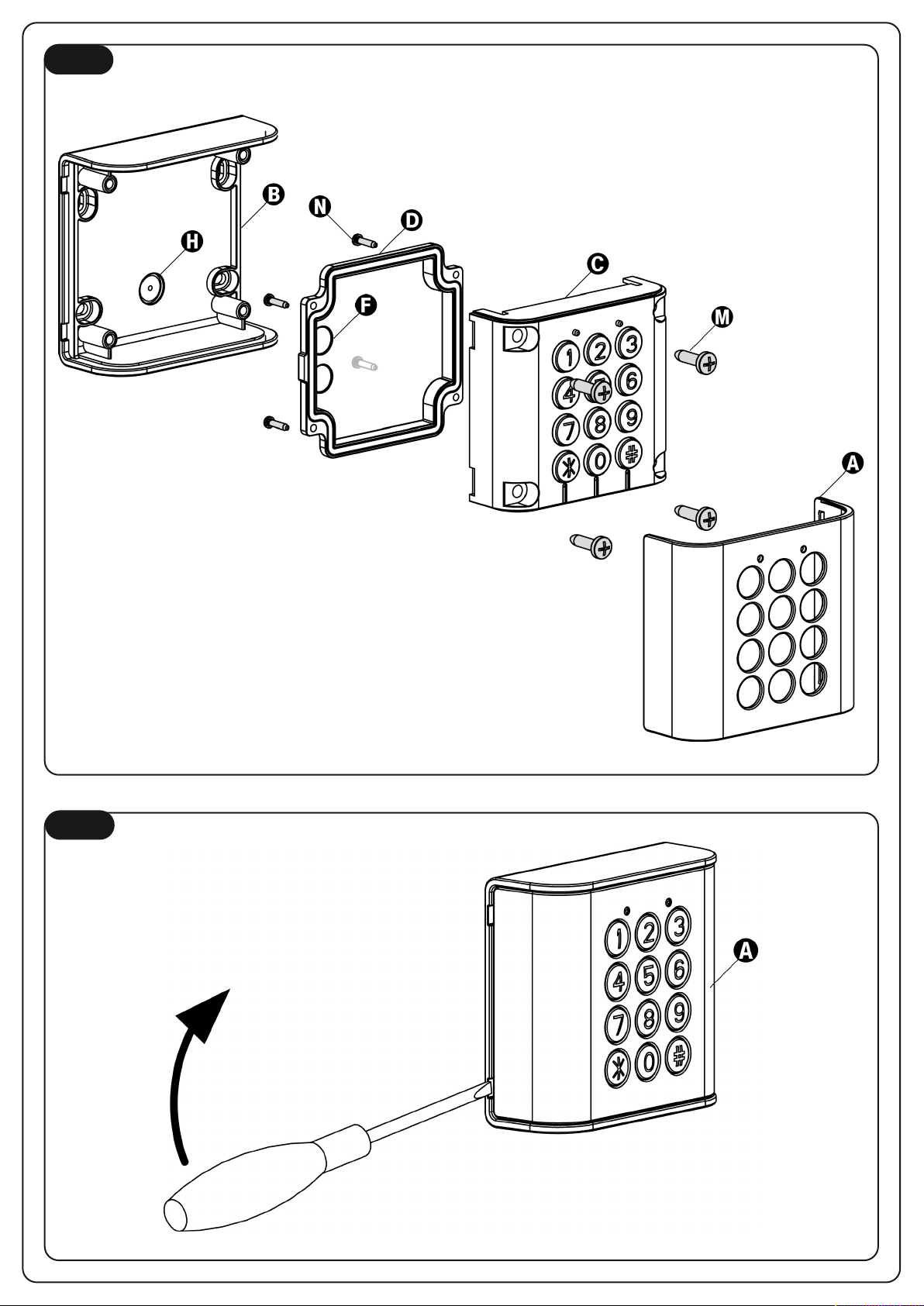
Fig. 1
Fig. 2
Page 3
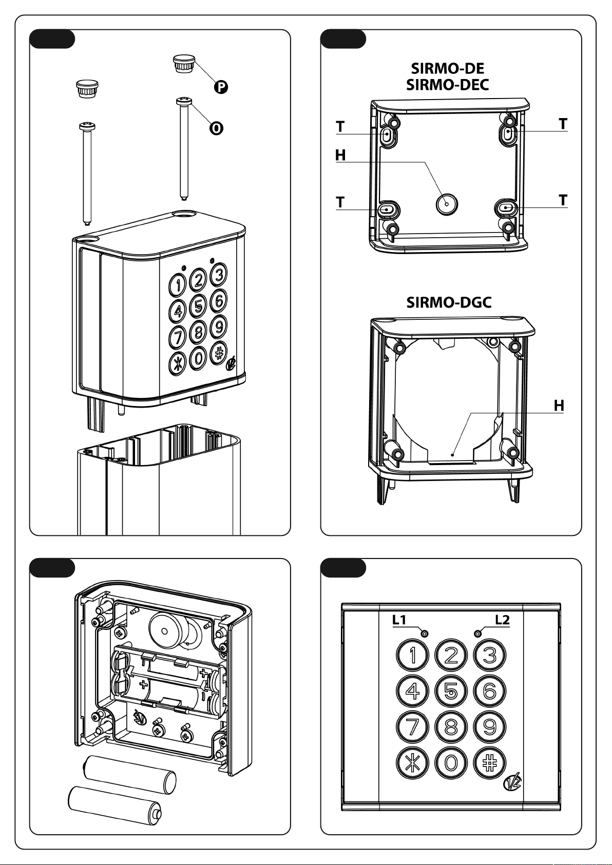
Fig. 3 Fig. 4
Fig. 5 Fig. 7
Page 4
ig. 7
F
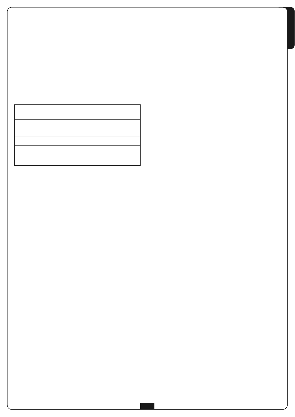
COLLEGAMENTI
ELETTRICI
Ingresso N.C. per il
1
collegamento di un sensore
12 VAC/VDC (J1 chiuso)
2
24 VAC/VDC (J1 aperto)
3 GND GND GND GND
4 Codice Code Code Código
5 Non utilizzato Not used Non utilisé No se utiliza
CONEXÕES
ELÉCTRICAS
Entrada N.C. para a conexão
1
com um sensor
12 VAC/VDC (J1 fechado)
2
24 VAC/VDC (J1 aberto)
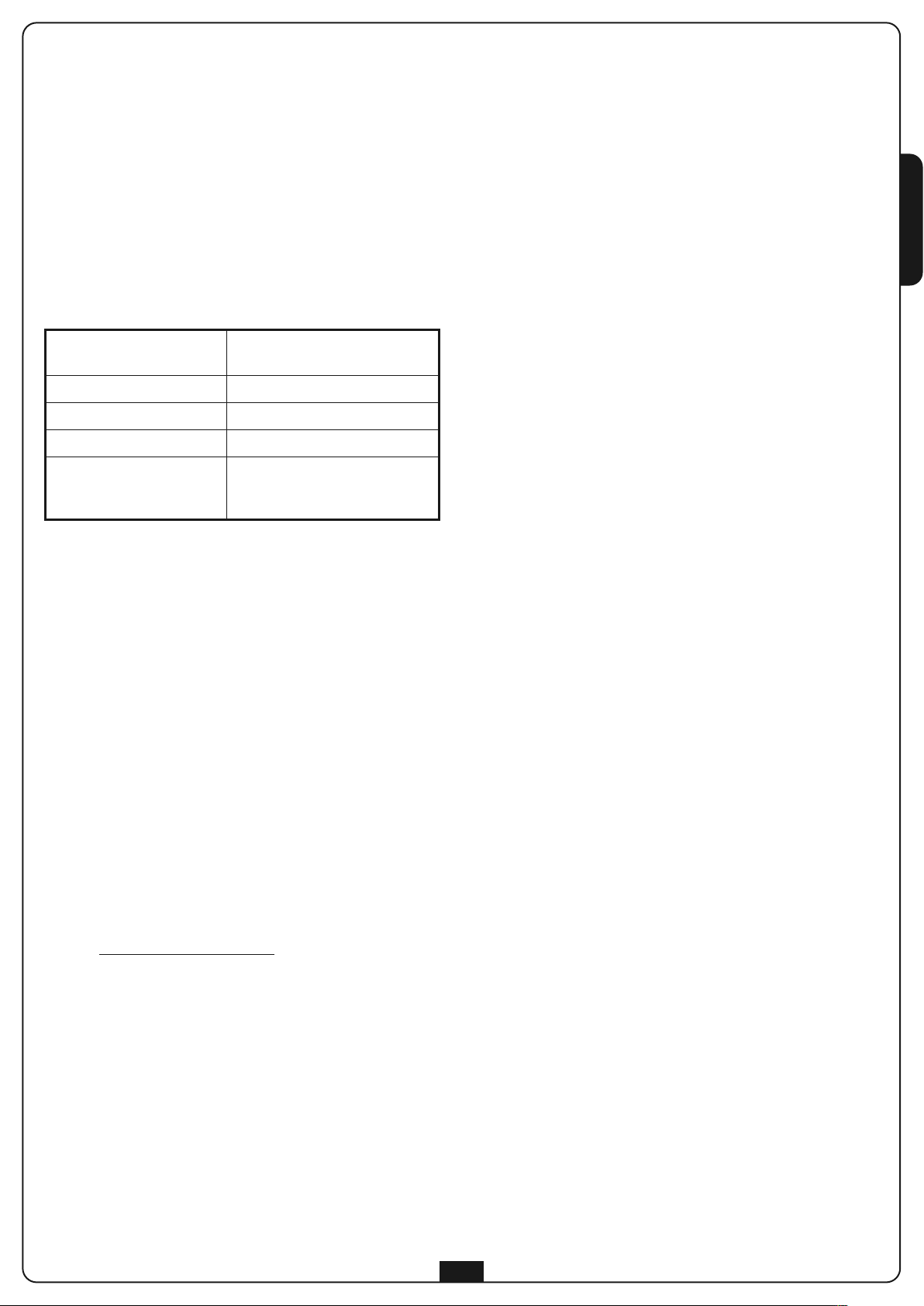
ELECTRICAL
CONNECTIONS
N.C. input for sensor
connection
12 V AC/DC (J1 closed)
24 V AC/DC (J1 open)
ELEKTRISCHE
ANSCHLÜSSE
Eingang N.C. für den Anschluss
eines Sensors
12 VAC/VDC (J1 geschlossen)
24 VAC/VDC (J1 offen)
BRANCHEMENTS
ÉLECTRIQUES
Entrée N.F. pour la connexion
d'un capteur
12 VAC/VDC (J1 fermé)
24 VAC/VDC (J1 ouvert)
ELEKTRISCHE
AANSLUITINGEN
Ingang N.C. voor de
aansluiting van een sensor
12 VAC/VDC (J1 gesloten)
24 VAC/VDC (J1 geopend)
CONEXIONES
ELÉCTRICAS
Entrada N.C. para la conexión
de un sensor
12 VCA/VCC (J1 cerrado)
24 VCA/VCC (J1 abierto)
3 GND GND GND
4 Código Code Code
5 Não utilizado Nicht verwendet Niet gebruikt
4
Page 5
elettore digitale SIRMO-DIGIT
S
• Il selettore digitale è un trasmettitore che si attiva digitando
una combinazione personalizzata da 1 a 8 cifre sull'apposita
astiera numerica retro-illuminata
t
• Digitando il corretto codice di accesso il selettore digitale
trasmette un codice digitale via radio o via cavo, a seconda
della versione.
• Sono programmabili fino a 9 canali differenti
• Disponibile nella versioni via radio (con alimentazione a
doppia batteria AAA 1,5 Volt) o via cavo (con alimentazione
esterna fornita direttamente dalla centrale-decoder)
• Disponibile anche nella versione via radio da colonna
SIRMO-DG per colonne serie GARDO.
CARATTERISTICHE TECNICHE
IRMO-DE
S
1. Definire i punti previsti per l’installazione, tenendo conto che
è necessario fissare la base su una superficie lineare e piana
. Rimuovere il frontalino A facendo leva con un cacciavite
2
a taglio (Fig 2)
3. Svitare le 4 viti M ed estrarre il dispositivo C dalla base B (Fig 1)
4. Fissare la base sulla parete con dei tasselli adeguati tramite i 4
fori T (Fig.4).
5. Inserire il dispositivo nella base e fissare le 4 viti M (Fig 1)
6. Inserire il frontalino
SIRMO-DG
1. Rimuovere il tappo superiore della colonna.
2. Posizionare il dispositivo sopra la colonna, fissarlo utilizzando
e viti O in dotazione e inserire i due tappini P (Fig. 3).
l
ITALIANO
Alimentazione versione a batteria
Alimentazione versione cablata 12 / 24 Vac / dc
Potenza radio < 1mW
Consumo: Max. 25mA - Min. 1µA
Durata con batteria
2 x 1,5V AAA alkaline
1100mAh
36500 azionamenti
1 anno con 100
azionamenti al giorno
INSTALLAZIONE DELLE VERSIONI VIA RADIO
SIRMO-DE e SIRMO-DG
Prima di fissare il selettore digitale (VERSIONE RADIO) è
opportuno verificare che il sistema funzioni correttamente:
1. Aprire il dispositivo ed inserire le batterie in dotazione
seguendo attentamente le indicazioni riportate nei punti
1,2,3,4 del paragrafo SOSTITUZIONE DELLA BATTERIA
2. Programmare il tastierino e memorizzare un canale sul ricevitore
(leggere attentamente il manuale di istruzioni del ricevitore).
3. Posizionare il tastierino (senza fissarlo) e verificare che
trasmettendo il codice precedentemente memorizzato, il
ricevitore attivi l'uscita corrispondente.
4. Se il sistema funziona correttamente fissare il tastierino,
altrimenti ridurre la distanza dal ricevitore fino ad ottenere un
buon funzionamento.
m ATTENZIONE: Evitate di installare il selettore digitale
radio su superfici metalliche.
SOSTITUZIONE DELLA BATTERIA
Quando la batteria è scarica il dispositivo emette serie di BEEP e
lampeggi brevi per 2 secondi. E' necessario sostituire la batteria
In questa condizione non è possibile attivare la programmazione
del dispositivo.
Per sostituire la batteria procedere come segue:
1. Rimuovere il frontalino A facendo leva con un cacciavite
a taglio (Fig 2)
2. Svitare le 4 viti M ed estrarre il dispositivo C dalla base B (Fig 1)
3. Svitare le 4 viti N e togliere il coperchio posteriore D (Fig 1)
4. Inserire le batterie nell’apposito alloggiamento rispettando la
polarità indicata nel portabatterie (Fig.5)
.
m ATTENZIONE: Utilizzare solamente batterie ALCALINE
AAA 1,5V - 1100mA.
INSTALLAZIONE DELLA VERSIONE CABLATA
SIRMO-DEC
1. Definire il percorso dei canali per il passaggio dei cavi
2. Definire i punti previsti per l’installazione, tenendo conto che
è necessario fissare la base su una superficie lineare e piana.
3. Collegare il dispositivo (vedi paragrafo COLLEGAMENTI
ELETTRICI)
4. Fissare la base sulla parete con dei tasselli adeguati tramite i 4
fori T (Fig.4).
5. Inserire il dispositivo nella base e fissare le 4 viti M (Fig 1)
6. Inserire il frontalino
INSTALLAZIONE DELLA VERSIONE CABLATA
SIRMO-DGC
1. Rimuovere il tappo superiore e il vetrino frontale della colonna.
2. Portare i cavi per i collegamenti fino all’estremità superiore
della colonna facendoli passare nelle scanalature dietro le
fotocellule
3. Inserire il vetrino frontale della colonna facendolo scorrere
dall’alto
4. Collegare il dispositivo (vedi paragrafo COLLEGAMENTI
ELETTRICI)
5. Inserire il dispositivo nella base B e fissare le 4 viti M (Fig 1)
6. Inserire il frontalino
7. Posizionare il dispositivo sopra la colonna, fissarlo utilizzando
le viti O in dotazione e inserire i due tappini P (Fig. 3)
COLLEGAMENTI ELETTRICI
1. Rimuovere il frontalino A facendo leva con un cacciavite
a taglio (Fig 2)
2. Svitare le 4 viti M ed estrarre il dispositivo C dalla base B (Fig 1)
3. Svitare le 4 viti N e togliere il coperchio posteriore D
4. Forare il coperchio posteriore D ed inserire i passacavi in
dotazione
5. Far passare i cavi all’interno del foro H e dei passacavi F (Fig. 4)
6. Chiudere il coperchio D con le 4 viti N (Fig 1)
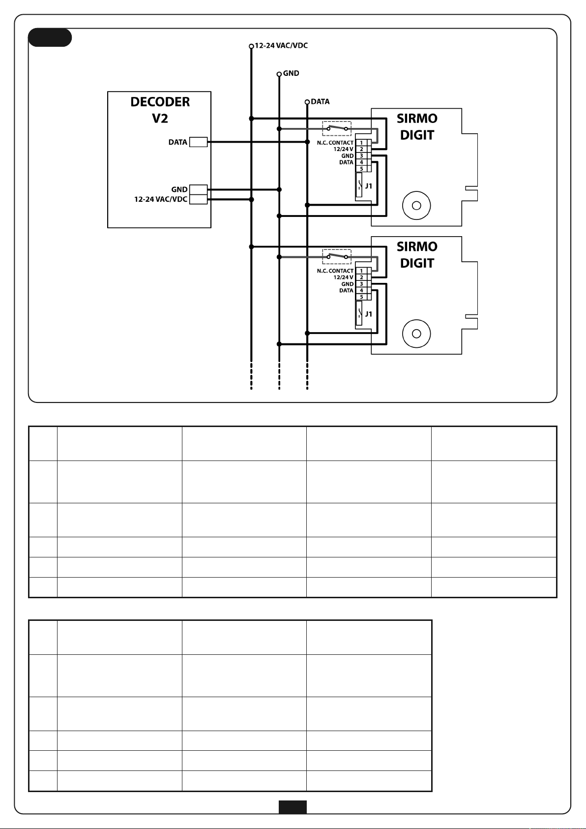
Per collegare uno o più dispositivi SIRMO-DEC a un decodificatore
V2 seguire lo schema di collegamento riportato in Fig. 7
Per collegare un dispositivo SIRMO-DEC a una centrale V2 con
ingresso dati seguire la procedura indicata nel manuale di
istruzioni della centrale.
L’ingresso 1 (N.C.) può essere utilizzato per il collegamento di un
sensore per segnalare lo stato (APERTO / CHIUSO) dell’accesso.
Quando l’ingresso si apre il led L2 si accende.
Se l'ingresso non è utilizzato e si desidera mantenetre spento il
led L2, ponticellare il morsetto 1 (N.C.) con il morsetto 3 (GND).
5
Page 6
UNZIONE DEI TASTI
F
Tasto ✱
• Durante la digitazione del codice di accesso la pressione del
tasto ✱ annulla l’operazione: il tastierino è immediatamente
ITALIANO
pronto per la digitazione di un nuovo codice.
• In fase di programmazione, la pressione del tasto ✱ annulla
tutte le operazioni e attiva la modalità STAND-BY.
In modalità STAND-BY serve a identificare la modalità di
•
funzionamento del dispositivo (vedi paragrafo seguente)
Tasto #
Serve per attivare la fase di programmazione e navigare
all’interno dei vari menù.
Tasti 0,1,2,3,4,5,6,7,8,9
In fase di programmazione servono per selezionare i menù e
•
per impostare i vari codici.
• Durante il funzionamento normale servono per digitare i
codici di accesso.
DENTIFICAZIONE DELLA MODALITÀ DI
I
FUNZIONAMENTO
Per identificare la modalità di funzionamento impostata è
sufficiente premere il tasto ✱ e contare il numero di lampeggi
emessi dai led L1 e L2 (nella versione cablata solo da L1):
- 1 lampeggio: modalità ROYAL
- 2 lampeggi: modalità 53200
- 3 lampeggi: modalità PERSONAL PASS
- 4 lampeggi: modalità PERSONAL PASS con logica di
funzionamento MONOSTABILE
SEGNALAZIONI
Le segnalazioni del dispositivo avvengono tramite due led (Fig. 6)
ed un buzzer.
Il buzzer emette un “beep” sonoro per segnalare ogni pressione
ei tasti. Digitando il codice d'accesso corretto, i due LED di
d
segnalazione L1 e L2 si accendono e si attiva la trasmissione del
codice.
MODALITÀ DI FUNZIONAMENTO
SIRMO-DIGIT può funzionare con 4 modalità di funzionamento
differenti a seconda del sistema a cui è associato.
ROYAL
• compatibilità con i trasmettitori a dip-switch che trasmettono a
433,92 MHz un codice di tipo ROYAL
• 4 codici di accesso disponibili
• il codice di accesso impostato attiva la trasmissione radio
• la trasmissione dura 2 secondi e viene segnalata tramite
l’accensione dei led L1 e L2
• ogni codice di accesso corrisponde ad un canale differente
53200
• compatibilità con i trasmettitori a dip-switch che trasmettono a
433,92 MHz un codice di tipo 53200 a 12 bit
• 4 codici di accesso disponibili
• il codice di accesso impostato attiva la trasmissione radio
• la trasmissione dura 2 secondi e viene segnalata tramite
l’accensione dei led L1 e L2
• ogni codice di accesso corrisponde ad un canale differente
PERSONAL PASS
• compatibilità con tutti trasmettitori a rolling code che
trasmettono a 433,92 / 868,3 MHz un codice di tipo
PERSONAL PASS
• 9 codici di accesso disponibili
• il codice di accesso impostato attiva la trasmissione radio
• la trasmissione dura 2 secondi e viene segnalata tramite
l’accensione dei led L1 e L2
• ogni codice di accesso corrisponde ad un canale differente
PERSONAL PASS - MONOSTABILE (solo versione RADIO)
• compatibilità con tutti trasmettitori a rolling code che
trasmettono a 433,92 / 868,3 MHz un codice di tipo
PERSONAL PASS
• 9 codici di accesso disponibili
• il codice di accesso impostato abilita per 5 secondi la
trasmissione radio che viene attivata premendo i tasti ✱ e #
• i due tasti ✱ e # corrispondono a 2 canali di un telecomando
(✱ = tasto1 e # = tasto3) e trasmettono sempre lo stesso
codice, indipendentemente dal codice di accesso digitato
• la trasmissione dura per tutto il tempo in cui il tasto ✱ o #
viene premuto e viene segnalata tramite dei BEEP
Se configurato in modalità “PERSONAL PASS - MONOSTABILE” i
due led restano accesi per 5s in attesa della pressione dei tasti ✱
o # che attivano la trasmissione in modalità MONOSTABILE.
Nella versione cablata si accende solo L1 per segnalare la
trasmissione. Il led L2 indica lo stato dell'ingresso N.C. (1) al quale
è possibile collegare un sensore per segnalare lo stato (APERTO /
CHIUSO) dell’accesso.
Tutte le altre segnalazioni avvengono in fase di programmazione
e vengono descritte successivamente.
PROGRAMMAZIONE
Il menu di programmazione permette di modificare i seguenti
parametri:
1. CODICE DI PROGRAMMAZIONE
2. CODICE DI ACCESSO
3. MODALITA' DI FUNZIONAMENTO: ROYAL, 53200, PERSONAL
PASS, PERSONAL PASS - MONOSTABILE
4. CODICE DIP-SWITCH (Solo versione Royal / 53200)
Normalmente il tastierino si trova in modalità STAND-BY cioè in
attesa di comando; la versione radio ha la retro-illuminazione
spenta per limitare i consumi della batteria, mentre la versione
cablata ha la retro-illuminazione sempre accesa.
In modalità di programmazione il selettore digitale torna nella
condizione STAND-BY nei seguenti casi:
• Se premete il tasto ✱ in qualsiasi fase della programmazione.
• Se lasciate passare più di un minuto tra la pressione
consecutiva di 2 tasti.
• Dopo il BEEP di 3 sec. accompagnato dall’accensione dei
2 LED che vi indica l'esecuzione corretta di una operazione.
• In caso di errore durante una fase di programmazione
qualsiasi: i due LED emettono dei lampeggi brevi per 3 sec.
poi il tastierino torna nella condizione di STAND-BY senza
salvare le nuove impostazioni.
In ogni caso se desiderate proseguire nella programmazione è
necessario ricominciare dalla digitazione del codice di
programmazione.
In modalità di funzionamento il selettore digitale torna in
modalità STAND-BY dopo 5 secondi di inattività.
6
Page 7

. CODICE di PROGRAMMAZIONE
1
Il codice di programmazione è la combinazione a 6 cifre da
digitare per modificare le impostazioni del tastierino.
l codice di fabbrica impostato è 999999.
I
Per garantire una maggior sicurezza del sistema si consiglia di
personalizzare il codice di programmazione e di custodire il nuovo
codice in un posto sicuro.
m ATTENZIONE: se il CODICE DI PROGRAMMAZIONE
viene perso non può essere ripristinato.
Il dispositivo deve essere rispedito al centro assistenza V2.
Personalizzazione del codice di
programmazione
OPERAZIONI DA ESEGUIRE
1. Digitare # + CODICE di PROGRAMMAZIONE + #
Segnalazione: 1 BEEP di 1,5 sec. + L1 e L2 accesi per 1,5 sec.
2. Digitare entro 1 minuto il TASTO 1 + #
Segnalazione: 1 BEEP + L1 acceso
ersonalizzazione del codice di accesso
P
OPERAZIONI DA ESEGUIRE SUL TASTIERINO
. Digitare # + CODICE di PROGRAMMAZIONE + #
1
Segnalazione: 1 BEEP di 1,5 sec. + L1 e L2 accesi per 1,5 sec.
2. Digitare entro 1 minuto il TASTO 2 + #
Segnalazione: 2 BEEP + L2 acceso
3. Digitare il NUMERO DEL CANALE SCELTO + #
Segnalazione: 1 BEEP di 1 sec. + L2 acceso
4. Digitare il CODICE DI ACCESSO scelto + #
Segnalazione: 1 BEEP di 1 sec. + L2 acceso
5. Ripetere il CODICE DI ACCESSO scelto + #
Segnalazione: - 1 BEEP di 3 sec. + L1 e L2 accesi se
l'operazione è corretta;
- lampeggi brevi dei LED se non corretta.
La stessa operazione deve essere ripetuta per ogni canale che
desiderate programmare.
ITALIANO
3. Ripetere il CODICE di PROGRAMMAZIONE + #
Segnalazione: 1 BEEP di 1 sec. + L1 acceso
4. Digitare il NUOVO CODICE DI PROGRAMMAZIONE + #
Segnalazione: 1 BEEP di 1 sec. + L1 acceso
5. Ripetere il NUOVO CODICE DI PROGRAMMAZIONE + #
Segnalazione: - 1 BEEP di 3 sec. + L1 e L2 accesi se
l'operazione è corretta;
- lampeggi brevi dei LED se non corretta.
ATTENZIONE: In caso di operazione non riuscita (es.:per avere
digitato codice scelto e codice di conferma diversi o per aver
atteso più di 1 minuto) il selettore digitale torna in modalità
STAND-BY mantenendo il codice di accesso originario ed è
necessario ripetere l'operazione dall'inizio.
2. CODICE di ACCESSO
Il codice di accesso è la combinazione da digitare per attivare la
trasmissione del codice digitale.
Il codice di fabbrica impostato per il canale 1 è 1111,
mentre gli altri canali sono disabilitati.
Per abilitare un canale è sufficiente impostare un codice di
accesso.
La prima cifra del codice è sempre identificativa del canale
di riferimento e non può essere modificata. Questo
significa che non sarà possibile assegnare al canale 1 ad
esempio, un codice di accesso diverso da 1 x x x x x x x , al
canale 2 un codice diverso da 2 x x x x x x x e così via.
ATTENZIONE: Ogni canale attivato deve essere memorizzato nel
ricevitore per poter funzionare.
NOTA: La possibilità di utilizzare codici di accesso composti da
una sola cifra, e quindi solo l'identificativo del canale, soddisfa
l'esigenza di utilizzare il selettore digitale come semplice
trasmettitore multi canale dove non sono richieste caratteristiche
di sicurezza. Alla pressione del singolo tasto corrisponderà
l'attivazione del canale corrispondente.
Disabilitazione di un canale
OPERAZIONI DA ESEGUIRE SUL TASTIERINO
1. Digitare # + CODICE di PROGRAMMAZIONE + #
Segnalazione: 1 BEEP di 1,5 sec. + L1 e L2 accesi per 1,5 sec.
2. Digitare entro 1 minuto il TASTO 2 + #
Segnalazione: 2 BEEP + L2 acceso
3. Digitare il NUMERO DEL CANALE SCELTO + #
Segnalazione: 1 BEEP di 1 sec.
4. Digitare il tasto 0 + #
Segnalazione: 1 BEEP di 1 sec.
5. Ridigitare il tasto 0 + #
Segnalazione: - 1 BEEP di 3 sec. + L1 e L2 accesi se
l'operazione è corretta;
- lampeggi brevi dei LED se non corretta.
3. MODALITA' DI FUNZIONAMENTO: ROYAL,
53200 o PERSONAL PASS
Selezionare la modalità di funzionamento in base al tipo di
telecomandi già utilizzati nel sistema.
OPERAZIONI DA ESEGUIRE SUL TASTIERINO
1. Digitare # + CODICE di PROGRAMMAZIONE + #
Segnalazione: 1 BEEP di 1,5 sec. + L1 e L2 accesi per 1,5 sec.
2. Digitare entro 1 minuto il TASTO 3 + #
Segnalazione: 3 BEEP + L1 e L2 accesi
3. • Digitare il TASTO 1 + # per selezionare la modalità ROYAL
• Digitare il TASTO 2 + # per selezionare la modalità 53200
• Digitare il TASTO 3 + # per selezionare la modalità P.PASS
• Digitare il TASTO 4 + # per selezionare la modalità P.PASS
con logica di funzionamento MONOSTABILE*
Segnalazione: 1 BEEP di 1 sec.
4. Ripetere per confermare (1 + # o 2 + # o 3 + # o 4 + #)
Segnalazione: - 1 BEEP di 3 sec. + L1 e L2 accesi se
l'operazione è corretta;
- lampeggi brevi dei LED se non corretta.
* solo versione RADIO
7
Page 8

. CODICE DIP- SWITCH
4
Il codice dip-switch di fabbrica impostato per il canale 1 è
0101010101 00.
Solo versione Royal / 53200)
(
ICHIARAZIONE DI CONFORMITÀ
D
V2 S.p.A. dichiara che le apparecchiature SIRMO-DIGIT sono
conformi ai requisiti essenziali fissati dalla direttiva
ITALIANO
Se nel ricevitore sono già memorizzati altri telecomandi bisogna
impostare il codice dip-switch del tastierino con la stessa
sequenza impostata sul dip-switch del telecomando.
Il dip-switch del telecomando è composto da una serie di 12
microinterruttori impostati su ON o su OFF. Per impostare la stessa
codifica sul tastierino bisogna digitare un codice composto da 12
cifre che saranno 0 o 1 a seconda della posizione dei
microinterruttori sul telecomando.
- Microinterruttore impostato su ON = 1
- Microinterruttore impostato su OFF = 0
Se il trasmettitore è monocanale il codice dip-switch da
impostare corrisponde alla posizione dei 12 microinterruttori.
Se il trasmettitore è bicanale e il tasto memorizzato nel
ricevitore è il 2, il codice dip-switch da impostare corrisponde alla
posizione dei 12 microinterruttori. Se il tasto memorizzato nel
ricevitore è il tasto 1, il codice dip-switch corrisponde alla posizione
dei microinterruttori da 1 a 10 più due cifre che sono 00.
Se il trasmettitore è quadricanale il codice dip-switch da
impostare corrisponde alla posizione dei microinterruttori da 1 a
10 più due cifre che sono:
• 00 se il tasto memorizzato nel ricevitore è il tasto 1
(esempio: 1010101010 00)
• 10 se il tasto memorizzato nel ricevitore è il tasto 2
(esempio: 1010101010 10)
• 01 se il tasto memorizzato nel ricevitore è il tasto 3
(esempio: 1010101010 01)
• 11 se il tasto memorizzato nel ricevitore è il tasto 4
(esempio: 1010101010 11)
2004/108/CEE compatibilità elettromagnetica
2006/95/CEE bassa tensione
99/5/CEE direttiva radio
e che sono state applicate le seguenti norme tecniche
EN 60950, EN 301 489-1, EN 301 489-3, EN 300 220-1
Racconigi, 11/02/2010
Il rappresentante legale V2 S.p.A.
Cosimo De Falco
Se nel ricevitore non è ancora stato memorizzato nessun
trasmettitore, il codice dip-switch può essere impostato
digitando una sequenza casuale di 12 cifre 0 o 1.
OPERAZIONI DA ESEGUIRE SUL TASTIERINO
1. Digitare # + CODICE di PROGRAMMAZIONE + #
Segnalazione: 1 BEEP di 1,5 sec. + L1 e L2 accesi per 1,5 sec.
2. Digitare entro 1 minuto il TASTO 4 + #
Segnalazione: 4 BEEP + L1 e L2 emettono lampeggi alternati
3. Digitare il NUMERO DEL CANALE SCELTO + #
Segnalazione: 1 BEEP di 1 sec. + L1 e L2 lampeggianti
4. Digitare il CODICE DIP-SWITCH scelto + #
Microinterruttore impostato su ON = 1
Microinterruttore impostato su OFF = 0
Segnalazione: - 1 BEEP di 3 sec. + L1 e L2 accesi se
l'operazione è corretta;
- lampeggi brevi dei LED se non corretta.
8
Page 9
IRMO-DIGIT digital switch
S
• The digital switch is a transmitter that is activated by entering
personalised 1 to 8 character combination on the special,
a
back-lit numerical keypad
• On entering the correct access code, the switch transmits a
digital code by radio or cable, depending on the exact version.
• They can be programmed with up to 9 different channels
• Available in radio (powered by two 1.5 Volt AAA batteries) or
cable (powered directly from the decoder-control unit)
versions
• Also available in a SIRMO-DG pillar radio version for GARDO
series pillars.
TECHNICAL SPECIFICATIONS
Battery powered version 2 x 1,5V AAA alkaline 1100mAh
IRMO-DE
S
1. Decide where the system should be installed, bearing in mind
that the base must be fixed on a flat, straight surface.
. Gently lever off the front panel A using a flat-head
2
screwdriver (Fig 2)
3. Unscrew the 4 screws M and extract the device C from the
base B (Fig 1)
4. Fix the base onto the wall using appropriate raw plugs by
means of the 4 through holes T (Fig.4)
5. Insert the device into the base and tighten the 4 screws M (Fig 1)
6. Insert the front panel
SIRMO-DG
1. Remove the upper cap from the pillar.
2. Position the device above the pillar, fix it in place using the
screws O supplied and insert the two caps P (Fig. 3)
ENGLISH
Cable powered version 12 / 24 Vac / dc
Radio power < 1mW
Consumption Max. 25mA - Min. 1µA
36500 transmissions
Battery lifetime
1 year with 100 transmissions
per day
INSTALLATION OF THE SIRMO-DE and
SIRMO-DG RADIO VERSIONS
Ensure that the system is operating correctly prior to fixing the
digital switch (RADIO VERSION):
1. Open the device and insert the batteries provided, following
the instructions given in parts 1,2,3,4 of the paragraph
BATTERY REPLACEMENT
2. Program the keypad and store a channel on the receiver (read
the receiver instruction manual carefully).
3. Position the keypad (without fixing it in place) and ensure
that when the previously stored code is transmitted, the
receiver activates the corresponding output.
4. If the system is operating correctly, fix the keypad, otherwise,
reduce the distance from the receiver in order for it to
operate correctly.
m PLEASE NOTE: Avoid installation of the digital radio
switch on metallic surfaces.
BATTERY REPLACEMENT
When the battery is run down, the device BEEPs and flashes for 2
seconds. The battery must be replaced
In this state, it is not possible to program the device.
To replace the battery, proceed as follows:
1. Gently lever off the front panel A using a flat-head
screwdriver (Fig 2)
2. Unscrew the 4 screws M and extract the device C from the
base B (Fig 1)
3. Unscrew the 4 screws N and remove the rear cover panel D
(Fig 1)
4. Insert the batteries in the special housing observing the
polarity marked on the battery cover (Fig 5)
.
m PLEASE NOTE: Only use 1.5 V – 1100 mAh AAA
ALKALINE batteries.
INSTALLATION OF THE SIRMO-DEC CABLED
VERSION
1. Decide the layout of the cable trays for running the cables
2. Decide where the system should be installed, bearing in mind
that the base must be fixed on a flat, straight surface.
3. Connect up the device (see the paragraph ELECTRICAL
CONNECTIONS)
4. Fix the base onto the wall using appropriate raw plugs by
means of the 4 through holes T (Fig 4)
5. Insert the device into the base and tighten the 4 screws M (Fig 1)
6. Insert the front panel
INSTALLATION OF THE SIRMO-DGC CABLED
VERSION
1. Remove the upper cap and the front glass from the pillar.
2. Run the connecting cables up to the upper end of the pillar,
passing them through the channelling behind the photocells.
3. Insert the pillar front glass by running it downwards from
above
4. Connect up the device (see the paragraph ELECTRICAL
CONNECTIONS)
5. Insert the device into the base and tighten the 4 screws M (Fig 1)
6. Insert the front panel
7. Position the device above the pillar, fix it in place using the
screws O supplied and insert the two caps P (Fig. 3)
ELECTRICAL CONNECTIONS
1. Gently lever off the front panel A using a flat-head
screwdriver (Fig 2)
2. Unscrew the 4 screws M and extract the device C from the
base B (Fig 1)
3. Unscrew the 4 screws N and remove the rear cover panel D.
4. Drill out the rear cover D and insert the cable glands provided
5. Pass the cables through the through hole H and cable glands
F (Fig. 4)
6. Close the rear cover D with the 4 screw N (Fig 1)
To connect one or more SIRMO-DEC devices to a V2 decoder,
follow the wiring diagram shown in Fig. 7
To connect a SIRMO-DEC device to a V2 control unit with data
input, follow the procedure indicated in the control unit
instruction manual.
Input 1 (N.C.) may be used for connection to a sensor for
indicating the status of the entrance (OPEN/CLOSED).
When the input is open, LED L2 is on.
If the input is not used, and it is desired to keep LED L2 off,
jumper terminal 1 (N.C.) with terminal 3 (GND).
9
Page 10
EY FUNCTIONS
K
The ✱ key
• While entering the access code, pressing the ✱ key cancels
the operation: The keypad is immediately ready for entering a
new code.
• During programming, pressing the ✱ key cancels all
operations and activates STAND-BY mode.
In STAND-BY mode, it is used to identify the operational
•
mode of the device (see the following section)
The # key
This is used to activate programming mode and navigate through
ENGLISH
the various programs.
The 0,1,2,3,4,5,6,7,8,9 keys
During programming, these are used to select the menus and
•
set the various codes.
• During normal operation, they are used to enter access codes.
DENTIFICATION OF THE OPERATIONAL
I
MODE
To identify the operational mode set, simply press the Q key and
count the number of flashes emitted by LEDs L1 and L2 (just LED
L1 in the cabled version):
1 flash: ROYAL mode
-
- 2 flashes: 53200 mode
- 3 flashes: PERSONAL PASS mode
- 4 flashes: PERSONAL PASS mode with MONOSTABLE
operating logic
SIGNALS
The device signals events by means of two LEDs (Fig. 6) and a
buzzer.
The buzzer emits a “beep” each time the keys are pressed. On
entering the correct access code, the two LEDs, L1 and L2 are lit
and code transmission activated.
OPERATIONAL MODE
SIRMO-DIGIT can operate in 4 different modes, depending on the
system with which it is associated.
ROYAL
• compatibility with dip-switch transmitters transmitting a
ROYAL type code at 433.92 MHz
• 4 access codes available
• the access code set activates the radio transmission
• transmission lasts for 2 seconds, and is indicated by LEDs L1
and L2 coming on
• each access code corresponds to a different channel
53200
• compatibility with dip-switch transmitters transmitting a
12-bit 53200 type code at 433.92 MHz
• 4 access codes available
• the access code set activates the radio transmission
• transmission lasts for 2 seconds, and is indicated by LEDs L1
and L2 coming on
• each access code corresponds to a different channel
PERSONAL PASS
• compatibility with all rolling code transmitters transmitting a
PERSONEL PASS type code at 433.92 MHz
• 9 access codes available
• the access code set activates the radio transmission
• transmission lasts for 2 seconds, and is indicated by LEDs L1
and L2 coming on
• each access code corresponds to a different channel
PERSONAL PASS - MONOSTABLE (only for RADIO models)
• compatibility with all rolling code transmitters transmitting a
PERSONEL PASS type code at 433,92 / 868,3 MHz
• 9 access codes available
• the access code set enables radio transmission for 5 seconds,
which is activated by pressing keys ✱ and
• the two keys, ✱ and #, correspond to 2 remote control
#
channels (✱ = key1 and
same code, independently of the access code entered
• transmission lasts for the entire time key ✱ or
and is signalled by BEEPS
= key3) and always transmit the
#
#
is pressed,
If configured in “PERSONAL PASS - monostable” mode, the two
LEDs remain on for 5 s while waiting for keys ✱ or
pressed, activating transmission in MONOSTABLE mode.
In the cabled version, just LED L1 is lit to indicate transmission.
LED L2 indicates the status of the input N.C. (1) to which it is
possible to connect a sensor for indicating the status of the
entrance (OPEN/CLOSED).
All other signals relate to programming and are described below.
#
to be
PROGRAMMING
The programming menu allows the modification of the following
parameters:
1. PROGRAMMING CODE
2. ACCESS CODE
3. WORKING MODE: ROYAL, 53200, PERSONAL PASS,
PERSONAL PASS - MONOSTABLE
4. DIP-SWITCH CODE (only version Royal/53200)
The keypad is normally in STAND-BY mode, i.e. awaiting
commands; the radio version has the back-light off in order to
save battery power, while in the cabled version, the back-light is
always on.
In programming mode, the keypad goes back to SLEEP mode in
the following cases:
• When pressing the key ✱ in any programming phase.
• When more than one minute pass between the pressure of
two consecutive keys.
• After the 3 second BEEP stating the correct execution of an
operation.
• In the case of an error during any of the programming steps:
the two LEDs flash briefly for 3 seconds, then the keypad
switches to STAND-BY mode without saving the new settings
In any case, if you want to go on with programming it is
necessary to start again from the entering of the programming
code.
In the working mode the digital selector goes back to STAND-BY
mode after 5 seconds of inactivity.
.
10
Page 11
. PROGRAMMING CODE
1
The programming code is the 6 digit combination to be entered
in order to change the keypad settings.
he factory code is 999999.
T
To guarantee more safety, we suggest customizing the
programming code and keeping the new one in a safe place.
m PLEASE NOTE: if the PROGRAMMING CODE is
ost/forgotten, it cannot be restored.
l
The device should be returned to the V2 assistance centre.
ustomization of the access code
C
OPERATIONS TO BE MADE ON THE KEYPAD
. Key in # + PROGRAMMING CODE + #
1
Signalling: 1 BEEP of 1,5 sec. + L1 and L2 on for 1,5 sec.
2. Key in within a minute the KEY 2 + #
Signalling: 2 BEEP + L2 on
3. Key in the NUMBER OF THE CHOSEN CHANNEL + #
Signalling: 1 BEEP of 1 sec. + L2 on
ENGLISH
Customization of the programming code
OPERATIONS TO BE MADE ON THE KEYPAD
1. Key in # + PROGRAMMING CODE + #
Signalling: 1 BEEP of 1,5 sec. + L1 and L2 on for 1,5 sec.
2. Key in within a minute the KEY 1 + #
Signalling: 1 BEEP + L1 on
3. Repeat the PROGRAMMING CODE + #
Signalling: 1 BEEP of 1 sec. + L1 on
4. Key in the NEW PROGRAMMING CODE + #
Signalling: 1 BEEP of 1 sec. + L1 on
5. Repeat the NEW PROGRAMMING CODE + #
Signalling: - 1 BEEP of 3 sec. + L1 and L2 on if the
operation is correct;
- short flashes of the LED if incorrect
WARNING: if the operation has failed (e.g. for having entered
chosen code and confirmation code different one from the other
or for having waited more then 1 minute) the digital selector
goes back to STAND-BY mode keeping the original access code
and it is necessary to start again
WARNING: in case of loss of the PROGRAMMING CODE, contact
V2 technical service.
4. Key in the NEW ACCESS CODE + #
Signalling: 1 BEEP of 1 sec. + L2 on
5. Repeat the NEW ACCESS CODE + #
Signalling: - 1 BEEP of 3 sec. + L1 and L2 on if the
operation is correct;
- short flashes of the LED if incorrect
Disabling a channel
OPERATIONS TO BE MADE ON THE KEYPAD
1. Key in # + PROGRAMMING CODE + #
Signalling: 1 BEEP of 1,5 sec. + L1 and L2 on for 1,5 sec.
2. Key in within a minute the KEY 2 + #
Signalling: 2 BEEP + L2 on
3. Key in the NUMBER OF THE CHOSEN CHANNEL + #
Signalling: 1 BEEP of 1 sec. + L2 on
4. Key in the KEY 0 + #
Signalling: 1 BEEP of 1 sec. + L2 on
5. Repeat the KEY 0 + #
Signalling: - 1 BEEP of 3 sec. + L1 and L2 on if the
operation is correct;
- short flashes of the LED if incorrect
2. ACCESS CODE
The access code is the combination to be keyed in to activate the
transmission of the digital code.
The factory code set for the channel 1 is 1111, while the
other channels are disabled.
To enable a channel just set an access code.
The first digit of the code always identifies the channel of
reference and can not be modified. This means that it
won't be possible to give to the channel 1, for instance, an
access code different from 1xxxxxxx, to the channel 2 an
access code different from 2xxxxxxx and so on.
PLEASE NOTE: To be able to function, each channel should be
memorised in the receiver.
NOTE: the possibility to use access codes made up by a unique
digit, therefore with the only identification digit of the channel,
makes the digital selector a simple multi channel transmitter, for
which no safety characteristics are required. Pressing the key, the
correspondent channel is started up.
3. WORKING MODE: ROYAL, 53200 or
PERSONAL PASS
Select the working mode according to the kind of remote
controls already used in the system.
OPERATIONS TO BE MADE ON THE KEYPAD
1. Key in # + PROGRAMMING CODE + #
Signalling: 1 BEEP of 1,5 sec. + L1 and L2 on for 1,5 sec.
2. Key in within a minute the KEY 3 + #
Signalling: 3 BEEP + L1 and L2 on
3. • Key in the KEY 1 + # to select ROYAL mode
• Key in the KEY 2 + # to select 53200 mode
• Key in the KEY 3 + # to select PERSONAL PASS mode
• Key in the KEY 4 + # to select P.PASS mode with
MONOSTABLE operating logic*
Signalling: 1 BEEP of 1 sec.
4. Repeat to confirm (1 + # or 2 + # or 3 + # or 4 + #)
Signalling: - 1 BEEP of 3 sec. + L1 and L2 on if the
operation is correct;
- short flashes of the LED if incorrect
* only for RADIO models
11
Page 12

. DIP-SWITCH CODE (only version
4
Royal/53200)
The factory dip-switch code set for channel 1 is 0101010101 00.
If other remote controls are already stored on the receiver, the
ip-switch code of the keypad has to be set with the same
d
sequence of the one set on the dip-switch of the remote control.
The dip-switch of the remote control is made up by a series of 12
micro switches set to ON or OFF.
To set the same code on the keypad, it is necessary to key in a
code made up of 12 digits: those will be 0 or 1, depending on
ENGLISH
the position of the micro switches on the remote control
- micro switch set to ON = 1
- micro switch set to OFF= 0
If the transmitter is single channel, the dip-switch to be set
coincides with the position of the 12 micro switches.
If the transmitter is two-channel and the key stored is 2, the
dip-switch code to be set coincides with the position of the 12
micro switches. If the key stored on the receiver is the key 1, the
dip-switch code coincides with the position of the micro switches
from 1 to 10 plus the 2 digit 00.
If the transmitter is four-channel, the dip-switch code to be
set coincides with the position of the micro switches from 1 to 10
plus 2 digits, which are:
• 00 if the key stored on the receiver is the key 1
(e.g. 1010101010 00)
• 10 if the key stored on the receiver is the key 2
(e.g. 1010101010 10)
• 01 if the key stored on the receiver is the key 3
(e.g. 1010101010 01)
• 11 if the key stored on the receiver is the key 4
(e.g. 1010101010 11)
ECLARATION OF CONFORMITY
D
V2 S.p.A. hereby declare that SIRMO-DIGIT equipment conforms
to the essential requirements established in the electromagnetic
ompatibility directive
c
2004/108/CEE electromagnetic compatibility
2006/95/EEC electrical safety
99/5/EEC directive radio
and that the following technical standards have been applied
EN 60950, EN 301 489-1, EN 301 489-3, EN 300 220-1
Racconigi, 11/02/2010
Legal representative, V2 S.p.A.
Cosimo De Falco
If no transmitter has been stored on the receiver, the
dip-switch code can be set entering a random sequence of 12
digits 0 or 1.
OPERATIONS TO BE MADE ON THE KEYPAD
1. Key in # + PROGRAMMING CODE + #
Signalling: 1 BEEP of 1,5 sec. + L1 and L2 on for 1,5 sec.
2. Key in within a minute the KEY 4 + #
Signalling: 4 BEEPs + L1 and L2 flashing alternately
3. Key in the NUMBER OF THE CHOSEN CHANNEL + #
Signalling: 1 BEEP of 1 sec. + L1 and L2 flashing alternately
4. Key in the CHOSEN DIP-SWITCH CODE + #
Micro switch set to ON = 1
Micro switch set to OFF = 0
Signalling: - 1 BEEP of 3 sec. + L1 and L2 on if the
operation is correct;
- short flashes of the LED if incorrect
12
Page 13

électeur digital SIRMO-DIGIT
S
• Le sélecteur digital est un transmetteur qui s'active en
introduisant une combinaison personnalisée de 1 à 8 chiffres
ur un clavier numérique prévu à cet effet avec éclairage de fond
s
• En tapant le code d'accès correct le sélecteur digital transmet
un code digital via radio ou via câble, selon la version.
• Ils sont programmables jusqu'à 9 canaux différents
• Ils sont disponibles dans les versions par radio (avec
alimentation à double batterie AAA 1,5 Volt) ou câblés (avec
alimentation extérieure fournie directement par la
centrale-décodeur)
• Disponible aussi dans la version par radio de colonne
SIRMO-DG pour colonnes séries GARDO.
CARACTÉRISTIQUES TECHNIQUES
Alimentation version à batterie
Alimentation version câblée 12 / 24 Vac / dc
Puissance radio < 1mW
Consommation Max. 25mA - Min. 1µA
Durée avec batterie
2 x 1,5V AAA alkaline
1100mAh
36500 actionnements
1 an avec 100 actionnements
par jours
INSTALLATION DES VERSIONS PAR RADIO
SIRMO-DE et SIRMO-DG
Avant de fixer le sélecteur digital (VERSION RADIO) il est
recommandé de vérifier que le système fonctionne correctement:
1. Ouvrir le dispositif et insérer les batteries en dotation en
suivant attentivement les indications reportées dans les points
1,2,3,4 du paragraphe REMPLACEMENT DE LA BATTERIE
2. Programmer le pavé numérique et mémoriser un canal sur le
récepteur (lire attentivement le manuel d'instructions du
récepteur).
3. Positionner le pavé numérique (sans le fixer), et vérifier qu'en
transmettant le code précédemment mémorisé, le récepteur
active la sortie correspondante.
4. Si le système fonctionne fixer le pavé numérique
correctement, autrement réduire la distance du récepteur
jusqu'à obtenir un bon fonctionnement.
m ATTENTION: Évitez d'installer le sélecteur digital radio
sur des surfaces métalliques.
REMPLACEMENT DE LA BATTERIE
Quand la batterie est déchargée le dispositif émet des BIP-BIP et
de brefs clignotements pendant 2 secondes.
Il est nécessaire de remplacer la batterie.
Dans cette condition l'activation de la programmation du
dispositif ne sera pas possible.
Pour remplacer la batterie procéder de la façon suivante:
1. Enlever le panneau de protection frontal A en faisant levier à
l’aide d’un tournevis plat (Fig.2)
2. Dévisser les 4 vis M et extraire le dispositif C de la base B
(Fig.1)
3. Dévisser les 4 vis N et enlever le couvercle arrière D (Fig.1)
4. Insérer les batteries dans le logement prévu à cet effet en
respectant la polarité indiquée dans le porte-batterie (Fig.5)
m ATTENTION: Utiliser seulement des batteries
ALCALINES AAA 1,5V - 1100mA.
IRMO-DE
S
1. Définir les points prévus pour l’installation, en tenant compte
qu’il est nécessaire de fixer la base sur une surface linéaire et
late
p
2. Enlever le panneau de protection frontal A en faisant levier à
l’aide d’un tournevis plat (Fig.2)
3. Dévisser les 4 vis M et extraire le dispositif C de la base B (Fig.1)
4. Fixer la base au mur avec des tampons prévus à cet effet au
moyen des 4 trous T (Fig.4)
5. Insérer le dispositif dans la base et fixer les 4 vis M (Fig.1)
6. Insérer le panneau de protection frontal
SIRMO-DG
1. Enlever le bouchon supérieur de la colonne.
2. Positionner le dispositif sur la colonne, le fixer en utilisant les
vis O en dotation et insérer les deux petits bouchons P (Fig. 3).
INSTALLATION DE LA VERSION CÂBLÉE
SIRMO-DEC
1. Définir le parcours des canaux pour le passage des câbles
2. Définir les points prévus pour l’installation, en tenant compte
qu’il est nécessaire de fixer la base sur une surface linéaire et
plate
3. Relier le dispositif (voir paragraphe BRANCHEMENTS
ÉLECTRIQUES)
4. Fixer la base au mur avec des tampons prévus à cet effet au
moyen des 4 trous T (Fig.4)
5. Insérer le dispositif dans la base et fixer les 4 vis M (Fig.1)
6. Insérer le panneau de protection frontal
INSTALLATION DE LA VERSION CÂBLÉE
SIRMO-DGC
1. Enlever le bouchon supérieur et le verre frontal de la colonne
2. Porter les câbles pour les branchements jusqu'à l'extrémité
supérieure de la colonne en les faisant passer dans les
rainures derrière les photocellules
3. Insérer le verre frontal de la colonne en le faisant glisser du haut.
4. Relier le dispositif (voir paragraphe BRANCHEMENTS
ÉLECTRIQUES)
5. Insérer le dispositif dans la base B et fixer les 4 vis M (Fig.1)
6. Insérer le panneau de protection frontal
7. Positionner le dispositif sur la colonne, le fixer en utilisant les
vis O en dotation et insérer les deux petits bouchons P (Fig. 3)
BRANCHEMENTS ÉLECTRIQUES
1. Enlever le panneau de protection frontal A en faisant levier à
l’aide d’un tournevis plat (Fig.2)
2. Dévisser les 4 vis M et extraire le dispositif C de la base B (Fig.1)
3. Dévisser les 4 vis N et enlever le couvercle arrière D (Fig.1)
4. Percer le couvercle arrière D et insérer les passe-câbles en
dotation
5. Faire passer les câbles dans les trous H des passe-câbles F (Fig.4)
6. Fermer le couvercle arrière D avec les 4 vis N (Fig.1)
Pour raccorder un ou plusieurs dispositifs SIRMO-DEC à un
décodeur V2 suivre le schéma de raccordement indiqué dans la
Fig.7
Pour relier un dispositif SIRMO-DEC à une armoire de commande
V2 avec entrée de données suivre la procédure indiquée dans le
manuel d'instructions de l'armoire de commande.
L'entrée 1 (N.F.) elle peut être utilisée pour relier un capteur et
signaler ainsi l'état (OUVERT / FERMÉ) de l'accès.
Quand l'entrée s'ouvre la DEL L2 s'allume.
Si l’entrée n’est pas utilisée et l’on souhaite laisser éteinte la DEL
L2, ponter la borne 1 (N.F) avec la borne 3 (GND).
13
FRANÇAIS
Page 14

ONCTION DES TOUCHES
F
Touche ✱
• Pendant l'introduction du code d'accès la pression de la
touche ✱ annule l'opération: le pavé numérique est prêt
immédiatement pour l'introduction d'un nouveau code.
• En phase de programmation, la pression de la touche ✱
annule toutes les opérations et active la modalité STAND-BY
Mode d'attente).
(
• En mode STAND-BY sert à identifier le mode de
fonctionnement du dispositif (voir paragraphe suivant)
Touche #
Elle sert pour activer la phase de programmation et naviguer à
l'intérieur des différents menus.
ouches 0,1,2,3,4,5,6,7,8,9
T
• En phase de programmation elles servent pour sélectionner
les menus et pour configurer les codes différents.
• Pendant le fonctionnement normal elles servent pour
ntroduire les codes d'accès.
i
FRANÇAIS
MODE DE FONCTIONNEMENT
SIRMO-DIGIT peut fonctionner avec 4 diverses modalités de
fonctionnement selon le système auquel il est associé.
ROYAL
• compatibilité avec les émetteurs à dip-switch émettant à
433,92 MHz un code de type ROYAL.
• 4 codes d'accès disponibles
• le code d'accès configuré active la transmission radio
• la transmission dure 2 secondes et elle est signalée par
l'allumage des voyants L1 et L2
• chaque code d'accès correspond à un canal différent
53200
• compatibilité avec les transmetteurs à dip-switch qui
transmettent à 433,92 MHz un code de type 53200 a 12 bit.
• 4 codes d'accès disponibles
• le code d'accès configuré active la transmission radio
• la transmission dure 2 secondes et elle est signalée par
l'allumage des voyants L1 et L2
• chaque code d'accès correspond à un canal différent
DENTIFICATION DE LA MODALITÉ DE
I
FONCTIONNEMENT
Pour identifier la modalité de fonctionnement configurée il suffit
de presser la touche ✱ et compter le nombre clignotements émis
par les DELs L1 et L2 (dans la version câblée seulement par L1) :
- 1 clignotement: modalité ROYAL
- 2 Clignotements: modalité 53200
- 3 Clignotements: modalité PERSONAL PASS
- 4 Clignotements: modalité PERSONAL PASS avec logique de
fonctionnement MONOSTABLE
SIGNALISATIONS
Les signalisations du dispositif sont données par deux voyants
(Fig. 6) et un buzzer.
Le buzzer émet un "bip" sonore pour signaler chaque pression
es touches. En introduisant le code d'accès correct, les deux
d
DELs de communication L1 et L2 s'allument et la transmission du
code s'active.
Si configuré en modalité "PERSONAL PASS - monostable" les
deux voyants restent allumés pendant 5 secondes dans l'attente
#
de la pression des touches ✱ ou
modalité MONOSTABLE.
Dans la version câblée seul L1 s'allume pour signaler la
transmission. La DEL L2 indique l'état de l'entrée N.F. (1) à
laquelle il est possible de relier un capteur pour signaler l'état,
OUVERT / FERMÉ, de l'accès.
Toutes les autres signalisations arrivent en phase de
programmation et elles sont décrites successivement.
qui activent la transmission en
PROGRAMMATION
Le menu de programmation permet de modifier les paramètres
suivants :
1. CODE DE PROGRAMMATION
2. CODE D'ACCES
3. MODALITE DE FONCTIONNEMENT : ROYAL, 53200,
PERSONAL PASS, PERSONAL PASS - MONOSTABLE
4. CODE DIP-SWITCH (seulement version Royal/53200)
PERSONAL PASS
• compatibilité avec tous transmetteurs à rolling code qui
transmettent à 433,92 MHz un code de type PERSONAL PASS
• 9 codes d'accès disponibles
• le code d'accès configuré active la transmission radio
• la transmission dure 2 secondes et elle est signalée par
l'allumage des voyants L1 et L2
• chaque code d'accès correspond à un canal différent
PERSONAL PASS - MONOSTABLE (seul version RADIO)
• compatibilité avec tous transmetteurs à rolling code qui
transmettent à 433,92 / 868,3 MHz un code de type
PERSONAL PASS
• 9 codes d'accès disponibles
• le code d'accès configuré active pendant 5 secondes la
transmission radio qui est activée en pressant les touches ✱
#
et
• les deux touches ✱ et #correspondent à 2 canaux d'une
#
télécommande (✱ = touche 1 et
transmettent toujours le même code, indépendamment du
code d'accès introduit
• la transmission dure pour tout le temps que la touche ✱ ou
est pressée et elle est signalée par des BIP
= touche 3) et
Le pavé numérique se trouve en modalité STAND-BY c'est-à-dire
dans l'attente de commandement; la version radio a le rétroéclairage éteint pour limiter les consommations de la batterie,
pendant que la version câblée a le rétro-éclairage toujours allumé.
En modalité programmation le sélecteur numérique retourne en
condition STAND-BY dans les cas suivants:
• En pressant la touche ✱ dans n'importe quelle phase de la
programmation.
• Si on laisse passer plus d'une minute entre la pression de 2
touches.
• Après le BIP de 3 secondes indiquant l'exécution correcte
d'une opération.
• En cas d'erreur pendant une phase de programmation
quelconque: les deux DELs émettent des clignotements brefs
pendant 3 secs puis le pavé numérique retourne dans la
condition de STAND-BY sans enregistrer les nouveaux
paramètres.
En tout cas, pour continuer dans la programmation il est
nécessaire de recommencer par l'introduction du code de
#
programmation.
En fonctionnement, le sélecteur numérique retourne en modalité
STAND-BY après 5 secondes d'inactivité.
14
Page 15

. CODE DE PROGRAMMATION
1
Le code de programmation est la combinaison à 6 chiffres à
introduire pour modifier les configurations du pavé numérique.
e code de fabrique è 999999.
L
Pour garantir la sécurité du système, nous conseillons de
personnaliser le code de programmation et de le garder en lieu
sûr.
m ATTENTION : si le CODE DE PROGRAMMATION est
perdu il ne peut pas être rétabli. Le dispositif doit être
renvoyé au service d'assistance après-vente V2
Personnalisation du code de programmation
OPERATIONS A EFFECTUER SUR LE CLAVIER
1. Frapper # + CODE de PROGRAMMATION + #
Signalisation: 1 BEEP de 1,5 sec. + L1 et L2 allumés pour
1,5 sec.
ersonnalisation du code d’accès
P
OPERATIONS A EFFECTUER SUR LE CLAVIER
1. Frapper # + CODE de PROGRAMMATION + #
Signalisation: 1 BEEP de 1,5 sec. + L1 et L2 allumés pour 1,5 sec.
2. Frapper dans 1 minute la TOUCHE 2 + #
Signalisation: 2 BEEP + L2 allumé
. Frapper le NUMERO DE LA VOIE choisie + #
3
Signalisation: 1 BEEP de 1 sec. + L2 allumé
4. Frapper le CODE D'ACCES choisi + #
Signalisation: 1 BEEP de 1 sec. + L2 allumé
5. Répéter le NOUVEAU CODE D'ACCES + #
Signalisation: - 1 BEEP de 3 sec. + L1 et L2 allumés si
l'opération est correcte;
- brefs clignotements des DELs si l'opération
'est pas correcte
n
FRANÇAIS
2. Frapper dans 1 minute la TOUCHE 1 + #
Signalisation: 1 BEEP + L1 allumé
3. Répéter le CODE de PROGRAMMATION + #
Signalisation: 1 BEEP de 1 sec. + L1 allumé
4. Frapper le NOUVEAU CODE de PROGRAMMATION + #
Signalisation: 1 BEEP de 1 sec. + L1 allumé
5. Répéter le NOUVEAU CODE de PROGRAMMATION + #
Signalisation: - 1 BEEP de 3 sec. + L1 et L2 allumés si
l'opération est correcte;
- brefs clignotements des DELs si l'opération
n'est pas correcte
ATTENTION: dans le cas d'opération non réussie (par exemple
pour avoir frappé code choisi et code de confirmation différents
entre eux ou pour avoir dépassé le temps d'une minute) le
sélecteur numérique retourne en modalité STAND-BY, en retenant
le code d'accès originel et on doit répéter l'entière opération.
ATTENTION: en cas de perte du CODE DE PROGRAMMATION,
contactez le service assistance technique V2.
2. CODE D'ACCES
Le code d'accès est la combinaison à frapper pour activer la
transmission du code numérique.
Le code de fabrique pour la voie 1 est 1111, alors que les
autres voies sont deshabilitées.
Pour habiliter une voie il suffit de régler un code d'accès.
e même procédé doit être suivi pour chaque voie qu'on veut
L
programmer.
Deshabilitation d'une voie
OPERATIONS A EFFECTUER SUR LE CLAVIER
1. Frapper # + CODE de PROGRAMMATION + #
Signalisation: 1 BEEP de 1,5 sec. + L1 et L2 allumés pour 1,5 sec.
2. Frapper dans 1 minute la TOUCHE 2 + #
Signalisation: 2 BEEP + L2 allumé
3. Frapper le NUMERO DE LA VOIE choisie + #
Signalisation: 1 BEEP de 1 sec. + L2 allumé
4. Frapper la TOUCHE 0 + #
Signalisation: 1 BEEP de 1 sec. + L2 allumé
5. Re-frapper la TOUCHE 0 + #
Signalisation: - 1 BEEP de 3 sec. + L1 et L2 allumés si
l'opération est correcte;
- brefs clignotements des DELs si l'opération
n'est pas correcte
La première chiffre du code identifie toujours la voie de
référence et ne peut pas être modifiée.
Ça veut dire qu'à la voie 1 n'est pas possible assigner un
code différent de 1xxxxxxx, à la voie 2 un code différent de
2xxxxxxx, et ainsi de suite.
ATTENTION : Chaque canal activé doit être mémorisé dans le
récepteur pour pouvoir fonctionner.
NOTE: La possibilité d'utiliser des codes d'accès d'une seule
chiffre, pourtant la seule identification de la voie, permet d'utiliser
le sélecteur numérique comme un simple émetteur à plusieurs
voies pour lequel ne sont pas requises caractéristiques de
sécurité. La pression de la touche activera la voie correspondante.
15
Page 16

. MODALITE DE FONCTIONNEMENT :
3
ROYAL, 53200 ou PERSONAL PASS
Sélectionner la modalité de fonctionnement selon le type
d'émetteurs déjà utilisés dans le système.
OPERATIONS A EFFECTUER SUR LE CLAVIER
1. Frapper # + CODE de PROGRAMMATION + #
Signalisation: 1 BEEP de 1,5 sec. + L1 et L2 allumés pour 1,5 sec.
2. Frapper dans 1 minute la TOUCHE 3 + #
Signalisation: 3 BEEP + L1 et L2 allumés
3. • Frapper la TOUCHE 1 + # pour sélectionner
la modalité ROYAL
• Frapper la TOUCHE 2 + # pour sélectionner
la modalité 53200
• Frapper la TOUCHE 3 + # pour sélectionner
a modalité PERSONAL PASS
l
• Frapper la TOUCHE 4 + # pour sélectionner la modalité
FRANÇAIS
P.PASS avec logique de fonctionnement MONOSTABLE*
Signalisation: 1 BEEP di 1 sec.
PERATIONS A EFFECTUER SUR LE CLAVIER
O
1. Frapper # + CODE de PROGRAMMATION + #
Signalisation: 1 BEEP de 1,5 sec. + L1 et L2 allumés pour 1,5
sec.
2. Frapper dans 1 minute la TOUCHE 4 + #
Signalisation: 4 BEEP + L1 et L2 émettent des clignotements
alternés
3. Frapper le NUMERO DE LA VOIE choisie + #
Signalisation: 1 BEEP de 1 sec. + L1 et L2 émettent des
clignotements alternés
4. Frapper le CODE DIP-SWITCH choise + #
Micro-interrupteur réglé sur ON = 1
Micro-interrupteur réglé sur OFF = 0
Signalisation: - 1 BEEP de 3 sec. + L1 et L2 allumés si
l'opération est correcte;
- brefs clignotements des DELs si l'opération
n'est pas correcte
4. Répéter pour confirmer (1 + # ou 2 + # ou 3 + # ou 4 + #)
Signalisation: - 1 BEEP de 3 sec. + L1 et L2 allumés si
l'opération est correcte;
- brefs clignotements des DELs si l'opération
n'est pas correcte
* Seul version RADIO
4. CODE DIP-SWITCH (Seul version Royal/53200)
Le code dip-switch de fabrique pour la voie 1 est 0101010101 00.
Si d'autres émetteurs ont déjà été mémorisés dans le récepteur, il
faut régler le code dip-switch du clavier avec la même séquence
réglée sur le dip-switch de l'émetteur.
Le dip-switch de l'émetteur est composée d'une série de 12
micro-interrupteurs réglés sur ON ou sur OFF. Pour régler la même
codification sur le clavier il faut frapper un code composé par 12
chiffres que sont 0 ou 1 selon la position des micro-interrupteurs
sur l'émetteur.
- Micro-interrupteur réglé sur ON = 1
- Micro-interrupteur réglé sur OFF = 0
Si l'émetteur est monocanale le code dip-switch à régler
correspond à la position des 12 micro-interrupteurs.
DÉCLARATION DE CONFORMITÉ
V2 S.p.A. déclare que les produits SIRMO-DIGIT sont conforment
aux qualités requises essentielles fixées par la directive:
2004/108/CEE compatibilité electromagnétique
2006/95/CEE sécurité électrique
99/5/CEE directive radio
et que les normes techniques suivantes ont été appliquées
EN 60950, EN 301 489-1, EN 301 489-3, EN 300 220-1
Racconigi, le 11/02/2010
Le représentant légal V2 S.p.A.
Cosimo De Falco
Si l'émetteur est bicanale et la touche mémorisée dans
l'émetteur
est la 2, le code dip-switch à régler correspond à la position des
12 micro-interrupteurs. Si la touche mémorisée dans l'émetteur
est la 1, le code dip-switch correspond à la position des microinterrupteurs de 1 à 10, plus deux chiffres que doivent être 00.
Si l'émetteur est quadricanale le code dip-switch à régler
correspond à la position des micro-interrupteurs de 1 à 10, plus
deux chiffres qui sont:
• 00 si la touche mémorisée dans le récepteur est la touche 1
(par exemple : 1010101010 00)
• 10 si la touche mémorisée dans le récepteur est la touche 2
(par exemple : 1010101010 10)
• 01 si la touche mémorisée dans le récepteur est la touche 3
(par exemple : 1010101010 01)
• 11 si la touche mémorisée dans le récepteur est la touche 4
(par exemple : 1010101010 11)
Si aucun récepteur n'a encore été mémorisé, le code dipswitch peut être réglé en frappant une séquence casuelle de 12
chiffres 0 ou 1.
16
Page 17

elector digital SIRMO-DIGIT
S
• El selector digital es un transmisor que se activa digitando una
combinación personalizada de 1 a 8 dígitos en el teclado
umérico retroiluminado
n
• Digitando el código correcto de acceso el selector digital
transmite un código digital vía radio o vía cable, según la versión
• Son programables hasta nueve canales diferentes
• Disponible en las versiones de radio (con alimentación de doble
batería AAA 1,5 Voltios) o de cable (con alimentación externa
proporcionada directamente de la centralita-decodificador)
• Disponible también en la versión de radio de columna
SIRMO-DG para columnas de la serie GARDO
CARACTERÍSTICAS TÉCNICAS
x 1,5V AAA alkaline
Alimentación en versión de batería
limentación en versión de cable12 / 24 Vac / dc
A
Potencia de radio < 1mW
Consumo Max. 25mA - Min. 1µA
Duración con batería
2
1100mAh
36500 accionamientos
1 año con 100
accionamientos al día
INSTALACIÓN DE LAS VERSIONES DE RADIO
SIRMO-DE Y SIRMO-DG
Antes de fijar el selector digital (VERSIÓN DE RADIO) es oportuno
verificar que el sistema funciona correctamente:
1. Abra el dispositivo e inserte las baterías proporcionadas
siguiendo atentamente las indicaciones dadas en los
puntos 1, 2, 3 y 4 del párrafo SUSTITUCIÓN DE LA BATERÍA
2. Programe el teclado y memorice un canal en el receptor (lea
atentamente el manual de instrucciones del receptor)
3. Coloque el teclado (sin fijarlo) y verifique que transmitiendo el
código memorizado anteriormente el receptor activa la salida
correspondiente
4. Si el sistema funciona correctamente fije el teclado;
alternativamente reduzca la distancia del receptor hasta
obtener un buen funcionamiento
m ATENCIÓN: Evite instalar el selector digital de radio
sobre superficies metálicas.
. Retire el frente A haciendo palanca con un destornillador
2
plano (Fig.2)
3. Retire los cuatro tornillos M y extraiga el dispositivo C de la
base B (Fig.1)
4. Fije la base sobre el muro con dos tacos adecuados mediante
los cuatro orificios T (Fig.4)
5. Inserte el dispositivo en la base y fije los cuatro tornillos M (Fig.1)
6. Inserte el frente
SIRMO-DG
1. Retire la tapa superior de la columna.
2. Coloque el dispositivo sobre la columna y fíjelo utilizando los
tornillos O provistos e inserte las dos tapitas P (Fig.3)
INSTALACIÓN DE LA VERSIÓN CABLEADA
SIRMO-DEC
1. Defina el trayecto de los conductos para el paso de los cables
de alimentación
2. Defina los puntos previstos para la instalación, teniendo en
cuenta que es necesario fijar la base sobre una superficie
uniforme y plana
3. Conecte el dispositivo (véase el párrafo CONEX. ELÉCTRICAS)
4. Fije la base sobre el muro con dos tacos adecuados mediante
los cuatro orificios T (Fig.4)
5. Inserte el dispositivo en la base B y fije los cuatro tornillos M
(Fig.1)
6. Inserte el frente
INSTALACIÓN DE LA VERSIÓN CABLEADA
SIRMO-DGC
1. Retire la tapa superior y la placa frontal de vidrio de la columna
2. Lleve los cables para las conexiones hasta el extremo superior
de la columna haciéndolos pasar en las ranuras por detrás de
las fotoceldas
3. Inserte la placa frontal de la columna haciéndolo deslizar
desde arriba
4. Conecte el dispositivo (véase el párrafo CONEX. ELÉCTRICAS)
5. Inserte el dispositivo en la base B y fije los cuatro tornillos M
(Fig.1)
6. Inserte el frente
7. Coloque el dispositivo sobre la columna y fíjelo utilizando los
tornillos O provistos e inserte las dos tapitas P (Fig.3)
ESPAÑOL
SUSTITUCIÓN DE LA BATERÍA
Cuando la batería se descarga el dispositivo emite un zumbido
(BEEP) e intermitencias breves durante dos segundos.
Es necesario sustituir la batería
activar la programación del dispositivo.
Para sustituir la batería proceda como se indica a continuación:
1. Retire el frente A haciendo palanca con un destornillador
plano (Fig. 2)
2. Retire los cuatro tornillos M y extraiga el dispositivo C de la
base B (Fig. 1)
3. Retire los 4 tornillos N y quite la tapa posterior D (Fig. 1)
4. Inserte las baterías en el alojamiento correspondiente
respetando la polaridad indicad en el portabaterías (Fig. 5)
. En esta condición no es posible
m ATENCIÓN: Utilice únicamente baterías ALCALINAS
AAA 1,5V - 1100mA.
SIRMO-DE
1. Defina los puntos previstos para la instalación, teniendo en
cuenta que es necesario fijar la base sobre una superficie
uniforme y plana
CONEXIONES ELÉCTRICAS
1. Retire el frente A haciendo palanca con un destornillador
plano (Fig.2)
2. Retire los cuatro tornillos M y extraiga el dispositivo C de la
base B (Fig.1)
3. Retire los 4 tornillos N y quite la tapa posterior D (Fig.1)
4. Taladre la tapa posterior D e inserte los prensaestopas
proporcionados
5. Haga pasar los cables por la perforación H y por los
prensaestopas F (Fig.4)
6. Cierrar la tapa posterior D con los 4 tornillos N (Fig.1)
Para conectar uno o más dispositivos SIRMO-DEC a un
decodificado V2 siga el esquema de conexión indicado en la Fig. 7
Para conectar un dispositivo SIRMO-DEC a una centralita V2 con
entrada de datos siga el procedimiento indicado en el manual de
instrucciones de la centralita.
La entrada 1 (N.C.) puede ser utilizada para la conexión de un
sensor para señalar el estado (ABIERTO / CERRADO) del acceso.
Cuando se abre la entrada, el diodo luminoso L2 se enciende.
Si la entrada no se utiliza y se desea mantener apagado el diodo
luminosos L2, haga un puente entre los bornes 1 (N.C.) y 3 (GND).
17
Page 18

UNCIÓN DE LAS TECLAS
F
Tecla ✱
• Durante la digitación del código de acceso la pulsación de la
tecla ✱ anula la operación: el teclado queda inmediatamente
listo para la digitación de un nuevo código.
• En la fase de programación, la pulsación de la tecla ✱ anula
todas las operaciones y activa la modalidad STAND-BY.
En modo STAND-BY sirve para identificar el modo de
•
funcionamiento del dispositivo (véase apartado siguiente)
Tecla #
Sirve para activar la fase de programación y navegar al interior de
los diversos menús.
Tecla 0,1,2,3,4,5,6,7,8,9
En la fase de programación sirven para seleccionar los menús
•
para programar los diversos códigos.
• Durante el funcionamiento normal sirven para digitar los
códigos de acceso.
DENTIFICACIÓN DE LA MODALIDAD DE
I
FUNCIONAMIENTO
Para identificar la modalidad de funcionamiento programada es
suficiente pulsar la tecla ✱ y contar el número de destellos emitidos
por los diodos luminosos L1 y L2 (en la versión cableada sólo L1).
- 1 destello: modalidad ROYAL
- 2 destellos: modalidad 53200
- 3 destellos: modalidad PERSONAL PASS
- 4 parpadeos: modo PERSONAL PASS con lógica de
funcionamiento MONOESTABLE
SEÑALIZACIONES
Las señales del dispositivo se producen mediante dos leds (Fig. 6)
y un zumbador.
El zumbador emite un “zumbido” sonoro para señalizar cualquier
ulsación de las teclas. Digitando el código de acceso correcto,
p
los dos diodos luminosos de señalización, L1 y L2, se encienden y
se activa la transmisión del código.
MODOS DE FUNCIONAMIENTO
SIRMO-DIGIT puede funcionar con 4 modos de funcionamiento
diferentes según el sistema al que está asociado.
ROYAL
• compatibilidad con los transmisores de interruptor DIP que
ESPAÑOL
transmiten a 433,92 MHz un código de tipo ROYAL
• 4 códigos de acceso disponibles
• el código de acceso programado activa la transmisión radio
• la transmisión dura 2 segundos y es señalada mediante el
encendido de los leds L1 y L2
• cada código de acceso corresponde a un canal diferente
53200
• compatibilidad con los transmisores de Interruptor DIP que
transmiten a 433,92 MHz un código de tipo 53200 a 12 bites
• 4 códigos de acceso disponibles
• el código de acceso programado activa la transmisión radio
• la transmisión dura 2 segundos y es señalada mediante el
encendido de los leds L1 y L2
• cada código de acceso corresponde a un canal diferente
PERSONAL PASS
• compatibilidad con todos los transmisores de código
alternante que transmiten a 433,92 MHz un código de tipo
PERSONAL PASS
• 9 códigos de acceso disponibles
• el código de acceso programado activa la transmisión radio
• la transmisión dura 2 segundos y es señalada mediante el
encendido de los leds L1 y L2
• cada código de acceso corresponde a un canal diferente
PERSONAL PASS - MONOESTABLE (solo version RADIO)
• compatibilidad con todos transmisores de código alternante
que transmiten a 433,92 / 868,3 MHz un código de tipo
PERSONAL PASS
• 9 códigos de acceso disponibles
• el código de acceso programado habilita durante 5 segundos
la transmisión radio que es activada pulsando las teclas ✱ y
• las dos teclas ✱ y # corresponden a 2 canales de un
#
telemando (✱ = tecla 1 y
mismo código, independientemente del código de acceso
tecleado
• la transmisión dura durante todo el tiempo en que la tecla ✱
#
es pulsada y es señalada mediante BIPS
o
= tecla 3) y transmiten siempre el
Si está configurado en modo “PERSONAL PASS - monoestable”
los dos leds permanecen encendidos durante 5 s esperando a que
se pulsen las teclas ✱ o # que activan la transmisión en modo
MONOESTABLE.
En la versión cableada se enciende sólo L1 para señalizar la
transmisión. El diodo L2 indica el estado de la entrada N.C. (1) a
la que es posible conectar un sensor para señalizar el estado
(ABIERTO / CERRADO) del acceso.
Todas las otras señalizaciones ocurren en la fase de programación
y se describen después.
PROGRAMACIÓN
El menu de programación permite modificar los siguientes
parámetros:
1. CÓDIGO DE PROGRAMACIÓN
2. CÓDIGO DE ACCESO
3. MODALIDAD DE FUNCIONAMIENTO: ROYAL, 53200,
PERSONAL PASS, PERSONAL PASS - MONOESTABLE
4. CÓDIGO DIP-SWITCH (solamente version Royal/53200)
Normalmente el teclado se encuentra en la modalidad STAND-BY,
es decir, en espera de comandos; la versión de radio presenta la
retroiluminación apagada para limitar el consumo de la batería,
mientras que la versión cableada tiene la retroalimentación
siempre encendida.
• Pulsando la tecla ✱ en cualquier fase de la programación.
• Si dejáis pasar más de un minuto entre la presión consecutiva
de 2 teclas.
• Después del BEEP de 3 segundos que le indica la ejecución
correcta de una operación.
• En caso de error durante una fase de programación cualquiera:
Los dos diodos luminosos emiten dos destellos breves durante
3 segundos; después el teclado vuelve a la condición de
reposo (STAND-BY) sin guardar las nuevas programaciones
#
En cualquier caso, para seguir con la programación es necesario
volver a empezar desde la introducción del código de
programación.
En modalidad de funcionamiento normal, el selector digital vuelve
en modalidad STAND-BY después de 5 segundos de inactividad.
.
18
Page 19

. CÓDIGO DE PROGRAMACIÓN
1
El código de programación es la combinación de 6 guarismos a
digitar para modificar la programación del teclado.
or defecto, el código de programación es 999999.
P
Para garantizar una mayor seguridad del sistema, aconsejamos
personalizar el código de programación y guardarlo en un lugar
seguro.
m ATENCIÓN: si se pierde el CÓDIGO DE
PROGRAMACIÓN no puede ser restablecido. El dispositivo
debe ser reenviado al centro de asistencia de V2.
ersonalización del código de acceso
P
OPERACIONES SOBRE EL TECLADO
. Teclear # + CÓDIGO DE PROGRAMACIÓN + #
1
Señalizaciones: 1 BEEP de 1,5 seg. + L1 y L2 encendidos
por 1,5 sec.
2. Teclear antes 1 minuto la TECLA 2 + #
Señalizaciones: 1 BEEP + L2 encendido
3. Teclear el NÚMERO DEL CANAL ELEGIDO + #
Señalizaciones: 1 BEEP di 1 seg. + L2 encendido
Personalización del código de programación
OPERACIONES SOBRE EL TECLADO
1. Teclear # + CÓDIGO DE PROGRAMACIÓN + #
Señalizaciones: 1 BEEP de 1,5 seg. + L1 y L2 encendidos
por 1,5 sec.
2. Teclear antes 1 minuto la TECLA 1 + #
Señalizaciones: 1 BEEP + L1 encendido
3. Repetir el CÓDIGO DE PROGRAMACIÓN + #
Señalizaciones: 1 BEEP di 1 seg. + L1 encendido
4. Teclear el NUEVO CÓDIGO DE PROGRAMACIÓN + #
Señalizaciones: 1 BEEP di 1 seg. + L1 encendido
5. Repetir el NUEVO CÓDIGO DE PROGRAMACIÓN + #
Señalizaciones: - 1 BEEP de 3 segundos + L1 y L2 encendidos
si la operación es correcta
- breves destellos de los LED si no es correcta
ATENCIÓN: En caso de operación no conseguida (por ejemplo
por haber tecleado código elegido y código de confirmación
diferentes o por haber esperado más de 1 minuto) el teclado
digital vuelve en modalidad STAND-BY manteniendo el código de
acceso predefinido y es necesario repetir la operación desde el
principio.
ATENCIÓN: En caso de perdida del código de programación, es
necesario contactar con el servicio de asistencia técnica de V2.
4. Teclear el CÓDIGO DE ACCESO + #
Señalizaciones: 1 BEEP di 1 seg. + L2 encendido
5. Repetir el CÓDIGO DE ACCESO + #
Señalizaciones: - 1 BEEP de 3 segundos + L1 y L2 encendidos
si la operación es correcta
- breves destellos de los LED si no es correcta
Deshabilitación de un canal
ESPAÑOL
OPERACIONES SOBRE EL TECLADO
1. Teclear # + CÓDIGO DE PROGRAMACIÓN + #
Señalizaciones: 1 BEEP de 1,5 seg. + L1 y L2 encendidos
por 1,5 sec.
2. Teclear antes 1 minuto la TECLA 2 + #
Señalizaciones: 1 BEEP + L2 encendido
3. Teclear el NÚMERO DEL CANAL ELEGIDO + #
Señalizaciones: 1 BEEP de 1 seg.
4. Teclear la TECLA 0 + #
Señalizaciones: 1 BEEP de 1 seg.
5. Repetir la TECLA 0 + #
Señalizaciones: - 1 BEEP de 3 segundos + L1 y L2 encendidos
si la operación es correcta
- breves destellos de los LED si no es correcta
2. CÓDIGO DE ACCESO
El código de acceso es la combinación que tiene que ser tecleada
para activar la transmisión del código digital.
Por defecto, el código para el canal 1 es 1111, mientras que
todos los otros canales están deshabilitados.
Para habilitar un canal, es suficiente programar un código de
acceso.
La primera cifra del código es siempre identificativa del
canal correspondiente y no puede ser modificada. Esto
significa que no será posible asignar al canal 1, por
ejemplo, un código de acceso diferente de 1xxxxxxx, al
canal 2 un código diferente de 2xxxxxxx, etc.
ATENCIÓN: Cada canal activado debe ser memorizado en el
receptor para poder funcionar.
NOTA: La posibilidad de utilizar códigos de acceso de una sola
cifra, por lo tanto solo el identificativo del canal, hace del selector
digital un simple transmisor multi canal por el cuál no se
requieren características de seguridad. Pulsando cada tecla, se
activará el canal correspondiente.
3. MODALIDAD DE FUNCIONAMIENTO:
ROYAL, 53200 o PERSONAL PASS
Seleccionar la modalidad de funcionamiento según el tipo de
emisor ya utilizado en el sistema.
OPERACIONES SOBRE EL TECLADO
1. Teclear # + CÓDIGO DE PROGRAMACIÓN + #
Señalizaciones: 1 BEEP de 1,5 seg. + L1 y L2 encendidos
por 1,5 seg.
2. Teclear antes 1 minuto la TECLA 3 + #
Señalizaciones: 1 BEEP + L1 y L2 encendidos
3. Teclear la TECLA 1 + # para seleccionar la modalidad ROYAL
Teclear la TECLA 2 + # para seleccionar la modalidad 53200
Teclear la TECLA 3 + # para seleccionar la modalidad P.PASS
Teclear la TECLA 4 + # para seleccionar el modo P. PASS con
lógica de funcionamiento MONOESTABLE*
Señalizaciones: 1 BEEP de 1 seg.
4. Repetir para confirmar (1 + # o 2 + # o 3 + # o 4 + #)
Señalizaciones: - 1 BEEP de 3 segundos + L1 y L2 encendidos
si la operación es correcta
- breves destellos de los LED si no es correcta
* solo version RADIO
19
Page 20

. CÓDIGO DIP-SWITCH
4
El código dip-switch predefinido del canal 1 es 0101010101 00.
i en el receptor ya están memorizados otros emisores, es
S
necesario programar el código dip-switch del teclado con la
misma secuencia del dip-switch del emisor.
El dip-switch del emisor es una serie de 12 micro interruptores
programados en ON u OFF. La codificación en el teclado se
efectua tecleando un código de 12 cifras que serán 0 o 1 según
la posición de los micro interruptores en el emisor.
- micro interruptor en ON = 1
- micro interruptor en OFF = 0
Si el emisor es monocanal el código dip-switch que tiene que
ser programado corresponde a la posición de los 12 micro
interruptores.
Si el emisor es bicanal y la tecla memorizada en el receptor es
la 2, el código dip-switch que tiene que ser programado
corresponde a la posición de los 12 micro interruptores. Si la la
tecla memorizada en el receptor es la tecla 1, el código dipswitch corresponde a la posición de los micro interruptores de 1 a
10 más dos cifras que son 00.
Si el emisor es cuadricanal el código dip-switch que tiene que
ser programado corresponde a la posición de los
microinterruptores de 1 a 10 más dos cifras que son:
ESPAÑOL
• 00 si la tecla memorizada en el receptor es la tecla 1
(ejemplo: 1010101010 00)
• 10 si la tecla memorizada en el receptor es la tecla 2
(ejemplo: 1010101010 10)
• 01 si la tecla memorizada en el receptor es la tecla 3
(ejemplo: 1010101010 01)
• 11 si la tecla memorizada en el receptor es la tecla 4
(ejemplo: 1010101010 11)
solo version Royal/53200)
(
ECLARACIÓN DE CONFORMIDAD
D
V2 S.p.A. declara que los productos SIRMO-DIGIT cumplen los
requisitos esenciales establecidos por las siguientes directivas:
2004/108/CEE Compatibilidad electromagnética
2006/95/CEE Seguridad eléctrica
99/5/CEE Directiva radio
y que son aplicadas las siguientes normas técnicas
EN 60950, EN 301 489-1, EN 301 489-3, EN 300 220-1
Racconigi, 11/02/2010
El representante legal de V2 S.p.A.
Cosimo De Falco
Si en el receptor no hay algún receptor memorizado, el
código dip-switch puede ser programado tecleando una
secuencia casual de 12 cifras 0 o 1.
OPERACIONES SOBRE EL TECLADO
1. Teclear # + CÓDIGO DE PROGRAMACIÓN + #
Señalizaciones: 1 BEEP de 1,5 seg. + L1 y L2 encendidos
por 1,5 seg.
2. Teclear antes 1 minuto la TECLA 4 + #
Señalizaciones: 4 BEEP + L1 y L2 emiten destellos alternados
3. Teclear el NÚMERO DEL CANAL ELEGIDO + #
Señalizaciones: 1 BEEP de 1 seg. + L1 y L2 emiten destellos
alternados
4. Teclear el CÓDIGO DIP-SWITCH elegido + #
Micro interruptor programado en ON = 1
Micro interruptor programado en OFF= 0
Señalizaciones: - 1 BEEP de 3 segundos + L1 y L2
encendidos si la operación es correcta
- breves destellos de los LED si no es correcta
20
Page 21

elector digital SIRMO-DIGIT
S
• O selector digital é um transmissor que se activa ao digitar
uma combinação personalizada de 1 a 8 algarismos no
equeno teclado numérico retroiluminado.
p
• Ao digitar o código de acesso correcto, o selector digital
transmite um código digital via rádio ou via cabo, consoante
a versão.
• É possível programar até 9 canais distintos
• Disponível na versão via rádio (com alimentação de dupla
bateria AAA 1,5 Volt) ou via cabo (com alimentação externa
fornecida directamente pelo quadro-decoder)
• Disponível também na versão via rádio da coluna SIRMO-DG
para colunas série GARDO.
CARACTERÍSTICAS TÉCNICAS
Alimentação versão com bateria
Alimentação versão cablada 12 / 24 Vac / dc
Potência rádio < 1mW
Consumo Max. 25mA - Min. 1µA
Duração com bateria
2 x 1,5V AAA alkaline
1100mAh
36500 accionamentos
1 ano, a considerar 100
accionamentos cada dia
INSTALAÇÃO DAS VERSÕES VIA RÁDIO
SIRMO-DE e SIRMO-DG
Antes de fixar o selector digital (VERSÃO RÁDIO) é oportuno
verificar o correcto funcionamento do sistema:
1. Abrir o dispositivo e inserir as baterias fornecidas seguindo
atentamente as indicações referidas nos pontos 1,2,3,4 do
parágrafo SUBSTITUIÇÃO DA BATERIA.
2. Programar o pequeno teclado e memorizar um canal no
receptor (ler atentamente o manual de instruções do receptor).
3. Posicionar o pequeno teclado (sem fixá-lo) e verificar se ao
transmitir o código precedentemente memorizado o receptor
activa a saída correspondente.
4. Se o sistema funciona correctamente fixar o pequeno teclado,
caso contrário reduzir a distância do receptor até obter um
bom funcionamento.
m ATENÇÃO: Evitar de instalar o selector digital rádio em
superfícies metálicas.
SUBSTITUIÇÃO DA BATERIA
Quando a bateria está descarregada o dispositivo emite BEEP e
piscadas durante 2 segundos. É necessário substituir a bateria
Nesta condição não é possível activar a programação do
dispositivo.
Para substituir a bateria proceder como indicado a seguir:
1. Remover a testa A usando como alavanca uma chave de
fenda (Fig 2).
2. Desparafusar os 4 parafusos M e extrair o dispositivo C da
base B (Fig 1)
3. Desparafusar os 4 parafusos N e retirar a tampa posterior D
(Fig 1)
4. Inserir as baterias no alojamento próprio respeitando a
polaridade indicada no porta baterias (Fig 5)
.
m ATENÇÃO: Utilizar somente baterias ALCALINAS AAA
1,5V - 1100mA.
IRMO-DE
S
1. Definir os pontos previstos para a instalação, considerando
que é necessário fixar a base numa superfície lisa e plana.
. Remover a testa A usando como alavanca uma chave de
2
fenda (Fig 2)
3. Desparafusar os 4 parafusos M e extrair o dispositivo C da
base B (Fig 1)
4. Fixar a base na parede com tacos adequados através dos 4
furos T (Fig.4)
5. Inserir o dispositivo na base e fixar os 4 parafusos M (Fig 1)
6. Inserir a testa
SIRMO-DG
1. Remover a tampa superior da coluna.
2. Posicionar o dispositivo na coluna, fixá-lo utilizando os
parafusos O fornecidos e inserir as duas tampinhas P (Fig. 3).
INSTALAÇÃO DA VERSÃO CABLADA
SIRMO-DEC
1. Definir o percurso dos canais para a passagem dos cabos
2. Definir os pontos previstos para a instalação, considerando
que é necessário fixar a base numa superfície lisa e plana
3. Conectar o dispositivo (ver parágrafo CONEXÕES
ELÉCTRICAS)
4. Fixar a base na parede com tacos adequados através do 4
furos T (Fig. 4)
5. Inserir o dispositivo na base B e fixar os 4 parafusos M (Fig 1)
6. Inserir a testa
INSTALAÇÃO DA VERSÃO CABLADA
SIRMO-DGC
1. Remover a tampa superior e o vidro frontal da coluna
2. Levar os cabos de conexão até à extremidade superior da
coluna passando-os nas ranhuras atrás das células
fotoeléctricas
3. Inserir o vidro frontal da coluna a fazê-lo correr do alto
4. Conectar o dispositivo (ver parágrafo CONEXÕES
ELÉCTRICAS)
5. Inserir o dispositivo na base B e fixar os 4 parafusos M
6. Inserir a testa
7. Posicionar o dispositivo na coluna, fixá-lo utilizando os
parafusos O fornecidos e inserir as duas tampinhas P (Fig. 3)
CONEXÕES ELÉCTRICAS
1. Remover a testa A e levantá-la com uma chave de fenda
(Fig 2)
2. Desparafusar os 4 parafusos M e extrair o dispositivo C da
base B (Fig 1)
3. Desparafusar os 4 parafusos N e retirar a tampa posterior D
4. Furar a tampa posterior D e inserir os passa-cabos fornecidos
5. Passar os cabos pelo furo H e pelos passa-cabos F (Fig. 4)
6. Fechar a tampa posterior D com os 4 parafusos N (Fig 1)
Para conectar um ou vários dispositivos SIRMO-DEC com um
decodificador V2 seguir o esquema de conexão referido na Fig. 7
Para conectar um dispositivo SIRMO-DEC com um quadro V2
com entrada de dados seguir o processo indicado no manual de
instruções do quadro.
Entrada 1 (N.C.) pode ser utilizada para a conexão com um
sensor para assinalar o estado (ABERTO / FECHADO) do acesso.
Ao abrir a entrada o led L2 se acende.
Se a entrada não for utilizada e se deseja manter apagado o L2,
ligar o borne 1 (N.C.) com o borne 3 (GND).
PORTUGUÊS
21
Page 22

UNÇÃO DAS TECLAS
F
Tecla ✱
• Durante a digitação do código de acesso, premindo a tecla ✱
anula-se a operação: o pequeno teclado fica imediatamente
pronto para a digitação de um novo código.
• Em fase de programação, premindo a tecla ✱ anulam-se
todas as operações e activa-se a modalidade STAND-BY.
Em modalidade STAND-BY serve para identificar a modalidade
•
de funcionamento do dispositivo (ver parágrafo sucessivo)
Tecla #
Serve para activar a fase de programação e navegar nos diversos
menus.
Teclas 0,1,2,3,4,5,6,7,8,9
Em fase de programação servem para seleccionar os menus e
•
para recolocar os diferentes códigos.
• Durante o funcionamento normal servem para digitar os
códigos de acesso.
MODALIDADE DE FUNCIONAMENTO
SIRMO-DIGIT pode funcionar em 4 diferentes modalidades de
funcionamento, segundo o sistema ao qual está associado.
ROYAL
• compatibilidade com os transmissores de dip-switch que
transmitem a 433,92 MHz um código de tipo ROYAL
• 4 códigos de acesso disponíveis
• o código de acesso seleccionado activa a transmissão rádio
• a transmissão dura 2 segundos e é assinalada através do
acendimento dos led L1 e L2
• cada código de acesso corresponde a um canal distinto
53200
PORTUGUÊS
• compatibilidade com os transmissores de dip-switch que
transmitem a 433,92 MHz um código de tipo 53200 de
12 bit
• 4 códigos de acesso disponíveis
• o código de acesso seleccionado activa a transmissão rádio
• a transmissão dura 2 segundos e é assinalada através do
acendimento dos led L1 e L2
• cada código de acesso corresponde a um canal distinto
PERSONAL PASS
• compatibilidade com todos os transmissores de rolling code
que transmitem a 433,92 MHz um código de tipo PERSONAL
PASS
• 9 códigos de acesso disponíveis
• o código de acesso seleccionado activa a transmissão rádio
• a transmissão dura 2 segundos e é assinalada através do
acendimento dos led L1 e L2
• cada código de acesso corresponde a um canal distinto
PERSONAL PASS - MONOESTÁVEL
• compatibilidade com todos os transmissores de rolling code
que transmitem a 433,92 / 868,3 MHz um código de tipo
PERSONAL PASS
• 9 códigos de acesso disponíveis
• o código de acesso seleccionado habilita por 5 segundos a
transmissão rádio, a qual é activada premindo as teclas ✱ e #
• as duas teclas ✱ e # correspondem a 2 canais de um
telecomando (✱ = tecla 1 e # = tecla 3) e transmitem sempre
o mesmo código, independentemente do código de acesso
digitado
• a transmissão dura por todo o tempo em que a tecla ✱ ou #
permanece premida e é assinalada através dos BEEP
(Só versão RADIO)
DENTIFICAÇÃO DA MODALIDADE DE
I
FUNCIONAMENTO
Para identificar a modalidade de funcionamento configurada é
suficiente premir a tecla ✱ e contar o número de piscadas
emitidas pelos leds L1 e L2 (na versão cablada só pelo L1):
- 1 piscada: modalidade ROYAL
- 2 piscadas:modalidade 53200
- 3 piscadas:modalidade PERSONAL PASS
- 4 piscadas: modalidade PERSONAL PASS com lógica de
funcionamento MONOESTÁVEL
SINALIZAÇÕES
As sinalizações do dispositivo ocorrem através de dois led (Fig. 6)
e um buzzer.
O buzzer emite um “beep” sonoro para assinalar qualquer pressão
as teclas. Digitando o código de acesso correcto, os dois LEDs de
d
sinalização L1 e L2 se acendem activando a transmissão do código.
Com a configuração em modalidade “PERSONAL PASS -
onoestável” os dois led permanecem acesos durante 5
m
segundos, a aguardar que sejam premidas as teclas ✱ ou # que
activam a transmissão em modalidade MONOESTÁVEL.
Na versão cablada só se acende o L1 para assinalar a transmissão.
O led L2 indica o estado da entrada N.C. (1) à qual é possível
conectar um sensor para assinalar o estado (ABERTO / FECHADO)
do acesso.
Todas as outras sinalizações ocorrem em fase de programação e
são descritas a seguir.
PROGRAMAÇÃO
Il menu di programmazione permette di modificare i seguenti
parametri:
O menu de programação permite alterar os seguintes parametros:
1. CÓDIGO DE PROGRAMAÇÃO
2. CÓDIGO DE ACESSO
3. MODALIDADE DE FUNCIONAMENTO: ROYAL, 53200,
PERSONAL PASS, PERSONAL PASS - MONOESTÁVEL
4. CÓDIGO DIP-SWITCH (Só versão Royal / 53200)
Normalmente o pequeno teclado está na modalidade STAND-BY,
isto é aguardando o comando; a versão rádio tem a
retroiluminação apagada para limitar o consumo da bateria,
enquanto a versão cablada tem a retroiluminação sempre acesa.
Em modalidade de programação o selector digital volta à
condição SLEEP nos seguintes casos:
• Ao premir a tecla CLEAR em qualquer fase da programação.
• Ao deixar passar mais de um minuto entre a pressão
consecutiva de 2 teclas.
• Após o BIPE de 3 seg. que indica a execução correcta de uma
operação.
• No caso de erro durante uma qualquer fase de programação,
os dois LEDs emitem piscadas breves durante 3 segundos,
depois o pequeno teclado volta na condição de STAND-BY
sem salvar as novas configurações
Em todo o caso, quando se deseja continuar a programação, é
necessário recomeçar desde a digitação do código de
programação.
Em modalidade de funcionamento o selector digital volta à
modalidade SLEEP após 5 segundos de inactividade.
.
22
Page 23

. CÓDIGO de PROGRAMAÇÃO
1
O código de programação é a combinação de 6 algarismos a
serem digitados para alterar as configurações do pequeno teclado.
código de fábrica configurado é 999999
O
Para garantir maior segurança do sistema, aconselha-se
personalizar o código de programação e guardar o novo código
em lugar seguro.
ersonalização do código de acesso
P
OPERAÇÕES A SEREM EXECUTADAS
. Digitar # + CÓDIGO de PROGRAMAÇÃO + #
1
Sinalizações: 1 BEEP de 1,5 seg. + L1 e L2 acesos por 1,5 seg.
2. Digitar em até 1 minuto a TECLA 2 + #
Sinalizações: 2 BEEP + L2 aceso
m ATENÇÃO: se o CÓDIGO DE PROGRAMAÇÃO for
perdido não poderá mais ser repristinado. O dispositivo
deve ser reenviado ao centro de assistência V2.
Personalização do código de programação
OPERAÇÕES A SEREM EXECUTADAS
1. Digitar # + CÓDIGO de PROGRAMAÇÃO + #
Sinalizações : 1 BEEP de 1,5 seg. + L1 e L2 acesos por 1,5 seg.
2. DiDigitar em até 1 minuto a TECLA 1 + #
Sinalizações: 1 BEEP + L1 aceso
3. Repetir o CÓDIGO de PROGRAMAÇÃO + #
Sinalizações: 1 BEEP de 1 seg. + L1 aceso
4. Digitar o NOVO CÓDIGO DE PROGRAMAÇÃO + #
Sinalizações: 1 BEEP de 1 seg. + L1 aceso
5. Repetir o NOVO CÓDIGO DE PROGRAMAÇÃO + #
Sinalizações: - 1 BEEP de 3 seg. + L1 e L2 acesos para
operação correcta;
- piscadas curtas dos LEDs para operação não
correcta.
ATENÇÃO: No caso de insucesso da operação (ex.: por ter
digitado código escolhido e código de confirmação diferentes ou
por ter esperado mais de 1 minuto), o selector digital volta à
modalidade SLEEP e conserva o código de acesso originário. Será
então necessário repetir a operação desde o início.
ATENÇÃO: No caso de perda do CÓDIGO de PROGRAMAÇÃO
contactar o serviço de assistência técnica V2.
2. CÓDIGO de ACESSO
O código de acesso é a combinação a ser digitada para activar a
transmissão do código digital.
O código de fábrica configurado para o canal 1 é 1111,
sendo os outros canais desabilitados.
Para habilitar um canal é suficiente configurar um código de
acesso.
3. Digitar o NÚMERO DO CANAL ESCOLHIDO + #
Sinalizações: 1 BEEP de 1 seg. + L2 aceso
4. Digitar o CÓDIGO DE ACESSO escolhido + #
Sinalizações: 1 BEEP de 1 seg. + L2 aceso
5. Repetir o CÓDIGO DE ACESSO escolhido + #
Sinalizações: - 1 BEEP de 3 seg. + L1 e L2 acesos para
operação correcta;
- piscadas curtas dos LEDs para operação não
correcta.
A mesma operação deve ser repetida para cada canal que se
deseja programar.
Desabilitar um canal
OPERAÇÕES A SEREM EXECUTADAS
1. Digitar # + CÓDIGO de PROGRAMAÇÃO + #
Sinalizações: 1 BEEP de 1,5 seg. + L1 e L2 acesos por 1,5 seg.
PORTUGUÊS
2. Digitar em até 1 minuto a TECLA 2 + #
Sinalizações: 2 BEEP + L2 aceso
3. Digitar o NÚMERO DO CANAL ESCOLHIDO + #
Sinalizações: 1 BEEP de 1 seg. + L2 aceso
4. Digitar a TECLA 0 + #
Sinalizações: 1 BEEP de 1 seg.
5. Repetir a TECLA 0 + #
Sinalizações: - 1 BEEP de 3 seg. + L1 e L2 acesos para
operação correcta;
- piscadas curtas dos LEDs para operação não
correcta.
O primeiro algarismo do código é sempre identificativo do
canal de referência e não pode ser alterado. Isto significa
que não será possível atribuir ao canal 1, por exemplo, um
código de acesso diferente de 1 x x x x x x x , ao canal 2
um código diferente de 2 x x x x x x x e assim por diante.
ATENÇÃO: Cada canal activado deve ser memorizado no
receptor para poder funcionar.
NOTA: A possibilidade de utilizar códigos de acesso de um só
algarismo, e portanto apenas o identificativo do canal, satisfaz a
exigência de utilizar o selector digital como simples transmissor
multicanal quando não se requerem características de segurança.
Ao primir aquela única tecla activa-se o canal que lhe
corresponde.
23
Page 24

. MODALIDADE' DE FUNCIONAMENTO:
3
ROYAL, 53200 ou PERSONAL PASS
Seleccionar a modalidade de funcionamento na base do tipo de
telecomandos já utilizados no sistema.
PERAÇÕES A SEREM EXECUTADAS
O
1. Digitar # + CÓDIGO de PROGRAMAÇÃO + #
Sinalizações: 1 BEEP de 1,5 seg. + L1 e L2 acesos por 1,5 seg.
2. Digitar em até 1 minuto a TECLA 3 + #
Sinalizações: 3 BEEP + L1 e L2 acesos
3. • Digitar a TECLA 1 + # para seleccionar a modalidade ROYAL
• Digitar a TECLA 2 + # para seleccionar a modalidade 53200
• Digitar a TECLA 3 + # para seleccionar a modalidade P.PASS
• Digitar a TECLA 4 + # para seleccionar a modalidade P.PASS
com lógica de funcionamento MONOESTÁVEL*
Sinalizações: 1 BEEP de 1 seg.
4. Repetir para confirmar (1 + # ou 2 + # ou 3 + # ou 4 + #)
Sinalizações: - 1 BEEP de 3 seg. + L1 e L2 acesos para
operação correcta;
- piscadas curtas dos LEDs para operação não
correcta.
PERAÇÕES A SEREM EXECUTADAS
O
1. Digitar # + CÓDIGO de PROGRAMAÇÃO + #
Sinalizações: 1 BEEP de 1,5 seg. + L1 e L2 acesos por 1,5 seg.
2. Digitar em até 1 minuto a TECLA 2 + #
Sinalizações: 4 BEEP + L1 e L2 emitem piscadas
alternativamente
3. Digitar o NÚMERO DO CANAL ESCOLHIDO + #
Sinalizações: 1 BEEP de 1 seg. + L1 e L2 emitem piscadas
alternativamente
4. Digitar o CÓDIGO DIP-SWITCH escolhido + #
Microinterruptor configurado no ON = 1
Microinterruptor configurado no OFF = 0
Sinalizações: - 1 BEEP de 3 seg. + L1 e L2 acesos para
operação correcta;
- piscadas curtas dos LEDs para operação não
correcta.
DECLARAÇÃO DE CONFORMIDADE
V2 S.p.A. declara que as aparelhagens SIRMO-DIGIT são
conformes aos requisitos essenciais estabelecidos pela directiva
*Só versão RADIO
4. CÓDIGO DIP- SWITCH (Só versão Royal/53200)
O código dip-switch de fábrica configurado para o canal 1 é
0101010101 00.
Se no receptor já foram memorizados outros telecomandos, é
necessário configurar o código dip-switch do pequeno teclado
com a mesma sequência configurada no dip-switch do
PORTUGUÊS
telecomando.
O dip-switch do telecomando é composto por uma série de 12
microinterruptores posicionados no ON ou no OFF. Para
configurar a mesma codificação no pequeno teclado é preciso
digitar um código composto por 12 algarismos, que poderão ser
0 ou 1 consoante a posição dos microinterruptores no
telecomando.
- Microinterruptor no ON = 1
- Microinterruptor no OFF = 0
Se o transmissor é monocanal o código dip-switch a ser
configurado corresponde à posição dos 12 microinterruptores.
Se o transmissor é bicanal e a tecla memorizada no receptor é
a 2, o código dip-switch a ser configurado corresponde à posição
dos 12 microinterruptores. Se a tecla memorizada no receptor é a
tecla 1, o código dip-switch corresponde à posição dos
microinterruptores de 1 a 10 mais dois algarismos que são 00.
2004/108/CEE Directiva compatibilidade electromagnética
2006/95/CEE Directiva Baixa Tensão
99/5/CEE Directiva Rádio
e que foram aplicadas as seguintes normas técnicas
EN 60950, EN 301 489-1, EN 301 489-3, EN 300 220-1
Racconigi, 11/02/2010
O representante legal V2 S.p.A.
Cosimo De Falco
Se o transmissor é quadricanal o código dip-switch a ser
configurado corresponde à posição dos microinterruptores de 1 a
10 mais dois algarismos que são:
• 00 se a tecla memorizada no receptor é a tecla 1 (exemplo:
1010101010 00)
• 10 se a tecla memorizada no receptor é a tecla 2 (exemplo:
1010101010 10)
• 01 se a tecla memorizada no receptor é a tecla 3 (exemplo:
1010101010 01)
• 11 se a tecla memorizada no receptor é a tecla 4 (exemplo:
1010101010 11)
Se no receptor ainda não foi memorizado nenhum transmissor, o
código dip-switch pode ser configurado digitando uma sequência
casual de 12 algarismos 0 ou 1.
24
Page 25

igitaler Wählschalter SIRMO-DIGIT
D
• Der digitale Wählschalter ist ein Sender, der durch Eingabe
einer aus 1 bis 8 Ziffern bestehenden persönlichen
ombination auf einer hintergrundbeleuchteten
K
Nummerntastatur aktiviert wird.
• Durch Eingabe des korrekten Zugangscodes sendet der
digitale Wählschalter je nach Version über Funk oder Kabel
einen digitalen Code.
• Bis zu 9 unterschiedliche Kanäle sind programmierbar.
• Erhältlich in Funkversion (Stromversorgung mit zwei AAA
1,5 Volt Batterien) oder Kabelversion (externe, direkt von
Steuerung-Decoder gelieferte Stromversorgung)
• Erhältlich auch in der Funkversion von Säule SIRMO-DG für
Säulen der Serie GARDO.
TECHNISCHE EIGENSCHAFTEN
tromversorgung Batterieversion
S
Stromversorgung Kabelversion 12 / 24 Vac / dc
Funkleistung < 1mW
Verbrauch Max. 25mA - Min. 1µA
Batteriedauer
2 x 1,5V AAA alkaline
1100mAh
36500 Betätigungen
1 Jahre bei 100
Betätigungen pro Tag
IRMO-DE
S
1. Die für die Installation vorgesehenen Punkte bestimmen und
darauf achten, dass die Basis auf einer geraden und flachen
läche montiert werden muss
F
2. Frontabdeckung A abnehmen, indem man sich mit einem
Schlitzschraubenzieher hilft (Abb. 2)
3. Die 4 Schrauben M herausschrauben und Gerät C von der
Basis B abziehen (Abb. 1)
4. Basis an der Wand mit den passenden Dübeln mit 4 Löchern
T befestigen (Abb.4)
5. Gerät in die Basis einsetzen und mit den 4 Schrauben befestigen
6. Frontabdeckung wieder befestigen
SIRMO-DG
1. Oberen Deckel der Säule abnehmen
2. Vorrichtung über der Säule positionieren und diese unter
erwendung der mitgelieferten Schrauben O befestigen und
V
die beiden Stöpsel P einführen (Abb. 3)
INSTALLATION DER KABELVERSION SIRMO-DEC
1. Verlauf der Kanäle für die Kabelpassage festlegen
2. Installationspunkte festlegen und beachten, dass die Basis auf
einer geraden und ebenen Fläche montiert werden muss
3. Vorrichtung anschließen (siehe Abschnitt ELEK. ANSCHLÜSSE)
4. Basis an der Wand mit den passenden Dübeln in 4 Löchern T
befestigen (Abb.4)
5. Vorrichtung in die Basis einsetzen und mit den 4 Schrauben
M befestigen (Abb. 1)
6. Frontabdeckung wieder befestigen
INSTALLATION DER FUNKVERSIONEN
SIRMO-DE und SIRMO-DG
Vor dem Befestigen des digitalen Wählschalters (FUNKVERSION)
wird empfohlen, zu prüfen, ob das System korrekt funktioniert:
1. Gerät öffnen, mitgelieferte Batterien einlegen und
aufmerksam die in den Punkten 1,2,3,4 des Abschnitts
BATTERIEWECHSEL aufgeführten Hinweise beachten
2. Tastatur programmieren und einen Kanal am Empfänger
(aufmerksam das Betriebshandbuch des Empfängers lesen)
3. Tastatur positionieren (ohne diesen zu befestigen) und
kontrollieren, ob bei Senden des vorher gespeicherten Codes
der Empfänger den entsprechenden Ausgang aktiviert
4. Wenn das System korrekt funktioniert, die Tastatur befestigen,
andernfalls die Entfernung vom Empfänger verringern bis
man die Übertragung einwandfrei funktioniert
m ACHTUNG: Den digitalen Wählschalter auf keinen Fall
auf metallischen Flächen montieren
BATTERIEWECHSEL
Wenn die Batterie leer ist, sendet das Gerät einen PIEPTON und
blinkt in kurzen Abständen 2 Sekunden lang.
Es ist notwendig, die Batterien zu wechseln.
In dieser Situation ist es nicht möglich, die Programmierung des
Geräts zu aktivieren.
Zum Batteriewechseln wie folgt vorgehen:
1. Frontabdeckung A abnehmen, indem man sich mit einem
Schlitzschraubenzieher hilft (Abb. 2)
2. Die 4 Schrauben M herausschrauben und Gerät C von der
Basis B abziehen (Abb. 1)
3. Die 4 Schrauben N herausschrauben und hinteren Deckel D
abnehmen (Abb. 1)
4. Batterien in das vorgesehene Fach unter Berücksichtigung der
im selben Fach gekennzeichneten Polarität einlegen (Abb.5)
m ACHTUNG: Ausschließlich Batterien des Typs ALCALINE
AAA 1,5V - 1100mA verwenden
INSTALLATION DER KABELVERSION SIRMO-DGC
1. Oberen Deckel und Frontglas der Säule abnehmen
2. Anschlusskabel bis zum oberen Ende der Säule ziehen, indem
man die durch die Nut hinter den Fotozellen passieren lässt
3. Frontglas der Säule wieder einsetzen, indem man es von oben
her einschiebt
4. Vorrichtung anschließen (siehe Abschnitt ELEK. ANSCHLÜSSE)
5. Vorrichtung in die Basis B einsetzen und mit den 4 Schrauben
M befestigen (Abb. 1)
6. Frontabdeckung wieder befestigen
7. Vorrichtung über der Säule positionieren und diese unter
Verwendung der mitgelieferten Schrauben O befestigen und
die beiden Stöpsel P einführen (Abb. 3)
ELEKTRISCHE ANSCHLÜSSE
1. Frontabdeckung A entfernen, indem man sich mit einem
Schlitzschraubenzieher hilft (Abb. 2)
2. Die 4 Schrauben M herausschrauben und Gerät C von der
Basis B abziehen (Abb. 1)
3. Die 4 Schrauben N herausschrauben und hinteren Deckel D
abnehmen
4. Loch in den hinteren Deckel D bohren und mitgelieferte
Kabelführungen einführen
5. Kabel durch das Loch H und die Kabelführungen F ziehen
(Abb. 4)
6. Deckel D mit den 4 Schrauben N schließen (Abb. 1)
Zum Anschließen einer oder mehrerer SIRMO-DEC Vorrichtungen
an einen V2 Decoder das in Abb. 7 aufgeführte Anschlussschema
beachten.
Zum Anschließen einer SIRMO-DEC Vorrichtung an eine V2
Steuerung mit Dateneingang die im Betriebshandbuch der
Steuerung aufgeführten Hinweise beachten.
Der Eingang 1 (N.C.)kann für den Anschluss eines Sensors für die
Statusmeldung (OFFEN/GESCHLOSSEN) des Zugangs verwendet
werden. Wenn der Eingang öffnet, schaltet sich LED L2 ein.
Wenn der Eingang nicht verwendet wird und man möchte, dass
LED L2 ausgeschaltet bleibt, Klemme 1 (N.C.) mit Klemme
3 (GND) überbrücken.
25
DEUTSCH
Page 26

ASTENFUNKTIONEN
T
Taste ✱
• Während der Eingabe des Zugangscodes kann man durch
Drücken der Taste ✱ die Operation annullieren: die Tastatur ist
auf der Stelle bereit für die Eingabe eines neuen Codes.
• In der Programmierphase kann man durch Drücken der Taste
✱ alle Operationen annullieren und den STAND-BY Modus
ktivieren.
a
• Im STAND-BY-Modus dient diese zum Erkennen des
Funktionsmodus der Vorrichtung (siehe nachfolgenden
Abschnitt)
RKENNUNG DES BETRIEBSMODUS
E
Zur Erkennung des eingestellten Betriebsmodus ist es
ausreichend, die Taste ✱ zu drücken und die Anzahl der von den
LEDs L1 und L2 abgegebenen Blinkzeichen zu zählen (bei der
Kabelversion nur von L1):
- 1 Blinkzeichen: Modus ROYAL
- 2 Blinkzeichen: Modus 53200
- 3 Blinkzeichen: Modus PERSONAL PASS
- 4 Blinkzeichen: Modus PERSONAL PASS mit Funktionslogik
MONOSTABIL
Taste #
Mit dieser Taste kann man die Programmierphase aktivieren und
innerhalb der unterschiedlichen Menüs navigieren.
Tasten 0,1,2,3,4,5,6,7,8,9
• In der Programmierphase dienen diese Tasten zur Wahl der
Menüs und zum Eingeben der unterschiedlichen Codes.
Während des Normalbetriebs dienen diese Tasten zur Eingabe
•
der Zugangscodes.
FUNKTIONSWEISE
SIRMO-DIGIT kann je nach dem, in welches System sie integriert
ist, mit 4 unterschiedlichen Funktionsweisen betrieben werden.
ROYAL
• Kompatibilität mit den Dip-Switch-Sendern, die mit
433,92 MHz einen Code vom Typ ROYAL senden
• 4 verfügbare Zugangscodes
• der eingestellte Zugangscode aktiviert die Funkübertragung
• die Übertragung dauert 2 Sekunden und wird durch
Einschalten der LEDs L1 und L2 angezeigt
• jeder Zugangscode entspricht einem unterschiedlichen Kanal
53200
• Kompatibilität mit den Dip-Switch-Sendern, die mit
433,92 MHz einen 12bit-Code vom Typ 53200 senden
• 4 verfügbare Zugangscodes
• der eingestellte Zugangscode aktiviert die Funkübertragung
• die Übertragung dauert 2 Sekunden und wird durch
DEUTSCH
Einschalten der LEDs L1 und L2 angezeigt
• jeder Zugangscode entspricht einem unterschiedlichen Kanal
PERSONAL PASS
• Kompatibilität mit allen Rolling Code-Sendern, die mit
433,92 MHz einen Code vom Typ PERSONAL PASS senden
• 9 verfügbare Zugangscodes
• der eingestellte Zugangscode aktiviert die Funkübertragung
• die Übertragung dauert 2 Sekunden und wird durch
Einschalten der LEDs L1 und L2 angezeigt
• jeder Zugangscode entspricht einem unterschiedlichen Kanal
PERSONAL PASS - MONOSTABIL (NUR FÜR FUNKMODELLE)
• Kompatibilität mit allen Rolling Code-Sendern, die mit
433,92 / 868,3 MHz einen Code vom Typ PERSONAL PASS
senden
• 9 verfügbare Zugangscodes
• der eingestellte Zugangscode aktiviert für 5 Sekunden die
Funkübertragung, die durch Drücken der Tasten ✱ und #
aktiviert wird
• die beiden Tasten ✱ und # entsprechen den 2 Kanälen einer
Fernbedienung (✱ = Taste1 und # = Taste3) und senden
unabhängig vom eingegebenen Zugangscode stets den
gleichen Code
• die Übertragung dauert solange die Taste 1 oder # gedrückt
wird und wird durch BEEP gemeldet
ANZEIGEN
Die Anzeigen der Vorrichtungen erfolgen mittels zwei LEDs (Abb.
6) und einen Buzzer.
Der Buzzer gibt bei jedem Drücken einer Taste einen Piepton ab.
Bei Eingabe des korrekten Zugangscodes schalten sich beiden
Anzeige-LEDs L1 und L2 ein und das Senden des Codes wird
aktiviert.
Bei Konfiguration auf den Modus “PERSONAL PASS monostabil” bleiben die beiden LEDs 5s lang eingeschaltet bis die
Tasten ✱ oder # gedrückt werden, die die Übertragung im Modus
MONOSTABIL aktivieren.
Bei der Kabelversion schaltet sich nur L1 zur Anzeige der
Übertragung ein. LED L2 zeigt den Zustand des Eingangs N.C. (1)
an, an den man einen Sensor zum Anzeigen des Zugangsstatus
(OFFEN/GESCHLOSSEN) anschließen kann.
Alle anderen Anzeigen erfolgen in der Programmierphase und
werden nachfolgend beschrieben.
PROGRAMMIERUNG
Das Programmiermenü ermöglicht das Ändern folgender
Parameter:
1. PROGRAMMIERCODE
2. ZUGANGSCODE
3. BETRIEBSMODUS: ROYAL, 53200, PERSONAL PASS,
PERSONAL PASS - MONOSTABIL
4. CODE DIP-SWITCH (nur Version Royal / 53200)
Normalerweise befindet sich die Tastatur im STAND-BY-Modus,
d.h. in Erwartung eines Befehls; bei der Funkversion ist die
Hintergrundbeleuchtung ausgeschaltet, um den Batterieverbrauch
zu verringern, während bei der Kabelversion die
Hintergrundbeleuchtung stets eingeschaltet ist.
Im Programmiermodus kehrt der digitale Wählschalter in
folgenden Fällen in den STAND-BY-Modus zurück:
• Wenn Taste ✱ während irgendeiner Programmierphase
gedrückt wird.
• Wenn zwischen dem aufeinanderfolgenden Drücken von
2 Tasten mehr als eine Minute vergeht.
• Nach dem 3 Sekunden langen PIEP-Ton, der durch das
Einschalten der 2 LEDs begleitet wird und die korrekte
Durchführung einer Operation meldet.
• Im Fall eines Fehlers während irgendeiner Programmierphase:
die beiden LEDs geben in kurzen Abständen 3 Sekunden lang
Blinkzeichen ab, dann kehrt die Tastatur in den STAND-BYModus zurück, ohne die neuen Einstellungen zu speichern.
Wenn die Programmierung fortgesetzt werden soll, muss auf
jeden Fall wieder mit der Eingabe des Programmiercodes
begonnen werden.
Im Betriebsmodus kehrt der digitale Wählschalter nach 5
Sekunden Inaktivität in den STAND-BY-Modus zurück.
26
Page 27

. PROGRAMMIERCODE
1
Der Programmiercode ist eine Kombination aus 6 Ziffern, die
eingegeben werden müssen, um die Einstellungen der Tastatur zu
ndern.
ä
Der eingestellte Fabrikcode ist 999999.
Um eine größere Systemsicherheit zu garantieren, wird
empfohlen, einen persönlichen Programmiercode zu verwenden
und diesen an einem sicheren Ort zu verwahren.
m ACHTUNG: wenn der PROGRAMMIERCODE verloren
geht, kann er nicht wiederhergestellt werden.
Die Vorrichtung muss dem Kundendienstzentrum der V2
zurückgesendet werden.
Einstellung eines persönlichen
Programmiercodes
DURCHZUFÜHRENDE OPERATIONEN
1. Eingabe # + PROGRAMMIERCODE + #
Anzeige: 1 PIEPTON von 1,5 s + L1 und L2 über 1,5 s
eingeschaltet
2. Eingabe innerhalb von 1 Minute TASTE 1 + #
Anzeige: 1 PIEPTON + L1 eingeschaltet
instellung des persönlichen Zugangscodes
E
AN DER TASTATUR DURCHZUFÜHRENDE OPERATIONEN
. Eingabe # + PROGRAMMIERCODE + #
1
Anzeige: 1 PIEPTON von 1,5 s + L1 und L2 über 1,5 s
eingeschaltet
2. Eingabe innerhalb von 1 Minute TASTE 2 + #
Anzeige: 2 PIEPTÖNE + L2 eingeschaltet
3. Eingabe ZIFFER DES GEWÄHLTEN KANALS + #
Anzeige: 1 PIEPTON von 1 s + L2 eingeschaltet
4. Eingabe gewählter ZUGANGSCODE + #
Anzeige: 1 PIEPTON von 1 s + L2 eingeschaltet
5. Wiederholung gewählter ZUGANGSCODE + #
Anzeige: - 1 PIEPTON von 3 s + L1 und L2 eingeschaltet,
wenn Operation korrekt ist;
- Blinkzeichen in kurzen Abständen der LEDs, wenn
Operation nicht korrekt ist.
Die gleiche Operation muss für jeden Kanal wiederholt werden,
den Sie programmieren möchten.
3. Wiederholung PROGRAMMIERCODE + #
Anzeige: 1 PIEPTON von 1 s + L1 eingeschaltet
4. Erneute Eingabe NEUER PROGRAMMIERCODE + #
Anzeige: 1 PIEPTON von 1 s + L1 eingeschaltet
5. Wiederholung NEUER PROGRAMMIERCODE + #
Anzeige: - 1 PIEPTON von 3 s + L1 und L2 eingeschaltet,
wenn Operation korrekt ist;
- Blinkzeichen in kurzen Abständen der LEDs,
wenn Operation nicht korrekt ist.
ACHTUNG: Bei fehlgeschlagener Operation (z.B.: bei
unterschiedlicher Eingabe des gewählten und des bestätigten
Codes oder nach Wartezeit über einer 1 Minute) kehrt der
digitale Wählschalter in den STAND-BY-Modus zurück, wobei der
ursprüngliche Code beibehalten wird und die Operation von
Beginn an wiederholt werden muss.
ACHTUNG: Im Fall des Verlustes des PROGRAMMIERCODES
kontaktieren Sie den Technischen Kundendienst von V2.
2. ZUGANGSCODE
Der Zugangscode besteht aus einer einzugebenden Kombination,
um das Senden des digitalen Codes zu aktivieren.
Der eingestellte Fabrikcode für Kanal 1 ist 1111, während
alle anderen Kanäle deaktiviert sind.
Um einen Kanal zu aktivieren, reicht es aus, einen Zugangscode
einzustellen.
Deaktivierung eines Kanals
AN DER TASTATUR DURCHZUFÜHRENDE OPERATIONEN
1. Eingabe # + PROGRAMMIERCODE + #
Anzeige: 1 PIEPTON von 1,5 s + L1 und L2 über 1,5 s
eingeschaltet
2. Eingabe innerhalb von 1 Minute TASTE 2 + #
Anzeige: 2 PIEPTÖNE + L2 eingeschaltet
3. Eingabe ZIFFER DES GEWÄHLTEN KANALS + #
Anzeige: 1 PIEPTON von 1 s
4. Drücken von Taste 0 + #
Anzeige: 1 PIEPTON von 1 s
5. Erneutes Drücken von Taste 0 + #
Anzeige: - 1 PIEPTON von 3 s + L1 und L2 eingeschaltet,
wenn Operation korrekt ist;
- Blinkzeichen in kurzen Abständen der LEDs,
wenn Operation nicht korrekt ist.
DEUTSCH
Die erste Ziffer des Codes identifiziert stets den
Bezugskanal und kann nicht verändert werden. Dies
bedeutet, dass es zum Beispiel nicht möglich ist, dem Kanal
1 einen Zugangscode zuzuordnen, der nicht mit
1 x x x x x x x beginnt, oder dem Kanal 2 einen Code, der
nicht mit 2 x x x x x x x beginnt und so weiter.
ACHTUNG: Jeder aktivierte Kanal muss im Empfänger
gespeichert werden, um zu funktionieren.
BEACHTE: Die Möglichkeit, Zugangscodes zu verwenden, die aus
nur einer einzigen Ziffer bestehen, das heißt aus der Kennziffer
des Kanals, entspricht der Notwendigkeit, den digitalen
Wählschalter als einfachen Mehrkanalsender zu verwenden, bei
dem keine Sicherheitskriterien erforderlich sind. Durch Drücken
der jeweiligen Taste wird der entsprechende Kanal aktiviert.
27
Page 28

. BETRIEBSMODUS: ROYAL, 53200 oder
3
PERSONAL PASS
Der Betriebsmodus wird je nach der bereits für das System
verwendeten Fernbedienung gewählt.
N DER TASTATUR DURCHZUFÜHRENDE OPERATIONEN
A
1. Eingabe # + PROGRAMMIERCODE + #
Anzeige: 1 PIEPTON von 1,5 s + L1 und L2 eingeschaltet
über 1,5 s
2. Drücken innerhalb 1 Minute der TASTE 3 + #
Anzeige: 3 PIEPTÖNE + L1 und L2 eingeschaltet
3. • Drücken von TASTE 1 + # für Betriebsmodus ROYAL
• Drücken von TASTE 2 + # für Betriebsmodus 53200
• Drücken von TASTE 3 + # für Betriebsmodus P.PASS
• Drücken von TASTE 4 + # für Betriebsmodus P.PASS mit
Funktionslogik MONOSTABILE* zu wählen.
Anzeige: 1 PIEPTON von 1 s
N DER TASTATUR DURCHZUFÜHRENDE OPERATIONEN
A
1. Eingabe # + PROGRAMMIERCODE + #
Anzeige: 1 PIEPTON von 1,5 s + L1 und L2 eingeschaltet
über 1,5 s
2. Eingabe innerhalb 1 Minute TASTE 4 + #
Anzeige: 4 PIEPTON + L1 und L2 geben abwechselnd
Blinkzeichen ab
3. Eingabe ZIFFER DES GEWÄHLTEN KANALS + #
Anzeige: 1 PIEPTON von 1 s + L1 und L2 blinkend
4. Eingabe gewählter DIP-SWITCH-CODE + #
Mikroschalter eingestellt auf ON = 1
Mikroschalter eingestellt auf OFF = 0
Anzeige: - 1 PIEPTON von 3 s + L1 und L2 eingeschaltet,
wenn Operation korrekt ist;
- Blinkzeichen in kurzen Abständen der LEDs,
wenn Operation nicht korrekt ist.
4. Wiederholen zum Bestätigen
(1 + # oder 2 + # oder 3 + # oder 4 + #)
Anzeige: - 1 PIEPTON von 3 s + L1 und L2 eingeschaltet,
wenn Operation korrekt ist;
- Blinkzeichen in kurzen Abständen der LEDs,
wenn Operation nicht korrekt ist.
* NUR FÜR FUNKMODELLE
4. CODE DIP- SWITCH (Nur Version Royal / 53200)
Der eingestellte Dip-Switch-Fabrikcode für Kanal 1 ist
0101010101 00.
Wenn im Empfänger bereits andere Fernbedienungen gespeichert
sind, ist der Dip-Switch-Code der Tastatur mit der gleichen Folge
einzustellen, die am Dip-Switch der Fernbedienung eingestellt wurde.
Der Dip-Switch der Fernbedienung besteht aus einer Reihe von
12 auf ON oder OFF gestellten Mikroschaltern. Um den gleichen
Code an der Tastatur einzustellen, ist ein aus 12 Ziffern
bestehender Code einzugeben, die je nach Position der sich an
der Fernbedienung befindenden Mikroschalter aus 0 oder 1
DEUTSCH
bestehen.
- Mikroschalter auf ON = 1
- Mikroschalter auf OFF = 0
KONFORMITÄTSERKLÄRUNG
V2 S.p.A. erklärt, dass die Geräte SIRMO-DIGIT konform mit den
wesentlichen Bestimmungen der Richtlinie:
2004/108/CEE EMC-Richtlinie
2006/95/CEE Niederspannungsrichtlinie
99/5/CEE Radiorichtlinie
sind und dass folgende technische Normen berücksichtigt
wurden:
EN 60950, EN 301 489-1, EN 301 489-3, EN 300 220-1
Racconigi, 11/02/2010
Der Gesetzlicher Vertreter der V2 S.p.A.
Cosimo De Falco
Wenn es sich einem Einkanalsender handelt, entspricht der
einzustellende Dip-Switch-Code der Position der 12 Mikroschalter.
Wenn es sich um einen Zweikanalsender handelt und die am
Empfänger gespeicherte Taste 2 ist, entspricht der einzustellende
Dip-Switch-Code der Position der 12 Mikroschalter. Wenn die am
Empfänger gespeicherte Taste 1 ist, entspricht der Dip-SwitchCode der Position der Mikroschalter 1-10 plus zwei Ziffern, die 00
sind.
Wenn es sich um einen Vierkanalsender handelt, entspricht
der einzustellende Dip-Switch-Code der Position der
Mikroschalter 1-10 plus zwei Ziffern, die:
• 00 sind, wenn die im Empfänger gespeicherte Taste
die Taste 1 ist (Beispiel: 1010101010 00)
• 10 sind, wenn die im Empfänger gespeicherte Taste
die Taste 2 ist (Beispiel: 1010101010 10)
• 01 sind, wenn die im Empfänger gespeicherte Taste
die Taste 3 ist (Beispiel: 1010101010 01)
• 11 sind, wenn die im Empfänger gespeicherte Taste
die Taste 4 ist (Beispiel: 1010101010 11)
Wenn im Empfänger noch kein Sender gespeichert wurde,
kann der Dip-Switch-Code durch Eingabe einer zufälligen Folge
von 12 aus 0 oder 1 bestehenden Ziffern eingestellt werden.
28
Page 29

igitale keuzeschakelaar SIRMO-DIGIT
D
• De digitale keuzeschakelaar is een zender die geactiveerd
wordt door intoetsen van een persoonlijke combinatie van
tot 8 cijfers op het speciale numerieke toetsenbordje met
1
achterverlichting
• Door de correcte toegangscode in te toetsen, zendt de
digitale keuzeschakelaar een digitale code uit via radio of via
kabel, al naargelang de versie.
• Er kunnen tot 9 verschillende kanalen geprogrammeerd
worden
• Beschikbaar in de versies via radio (met voeding met dubbele
AAA-batterij van 1,5 V) of via kabel (met externe voeding die
rechtstreeks door de centrale-decoder verstrekt wordt)
• Ook beschikbaar in de versie via radio met SIRMO-DG kolom,
voor kolommen van de serie GARDO.
TECHNISCHE KENMERKEN
Voeding versie met batterij
2 x 1,5V AAA alkaline
1100mAh
IRMO-DE
S
1. Bepaal de installatiepunten, rekening houdend met het feit
dat de basis op een rechte, vlakke ondergrond bevestigd
oet worden
m
2. Verwijder frontplaat A door met een schroevendraaier met
plat uiteinde druk uit te oefenen (Afb 2)
3. Draai de 4 schroeven M los en trek apparaat C los van basis B
(Afb 1)
4. Bevestig de basis op de muur door passende pluggen in de
4 gaten T te steken (Afb.4)
5. Plaats het apparaat op de basis en draai de 4 schroeven M
vast (Afb.1)
6. Breng de frontplaat aan
SIRMO-DG
1. Verwijder de bovenste dop van de kolom
2. Breng het apparaat bovenop de kolom in positie, zet het vast
met gebruik van de bijgeleverde schroeven O en breng de
dopjes P aan (Afb. 3)
2
Voeding versie bekabeling 12 / 24 Vac / dc
Radiovermogen < 1mW
Verbruik Max. 25mA - Min. 1µA
Duur met batterij
36500 activeringen
1 jaar met 100
aandrijvingen per dag
INSTALLATIE VAN DE VERSIES VIA RADIO
SIRMO-DE en SIRMO-DG
Alvorens de digitale keuzeschakelaar (RADIOVERSIE) te bevestigen,
is het zaak om te controleren of het systeem correct werkt:
1. Open het apparaat en plaats de bijgeleverde batterijen door
de aanduidingen van de punten 1, 2, 3 en 4 van de paragraaf
VERVANGING VAN DE BATTERIJ met aandacht te volgen
2. Programmeer het toetsenbordje en bewaar een kanaal in de
ontvanger (lees met aandacht de handleiding met instructies
van de ontvanger)
3. Breng het toetsenbordje in positie (zonder het te bevestigen)
en controleer of de ontvanger, bij uitzending van de eerder
bewaarde code, de overeenkomstige uitgang activeert
4. Indien het systeem correct werkt, het toetsenbordje
bevestigen of anders de afstand tot de ontvanger verkorten
tot een goede werking verkregen wordt
m LET OP: vermijd het de digitale keuzeschakelaar,
radioversie, op metalen oppervlakken te installeren
VERVANGING VAN DE BATTERIJ
Wanneer de batterij leeg is, zal het apparaat gedurende 2
seconden een BEEP laten horen en kort knipperen.
Nu moet de batterij vervangen worden
Onder deze omstandigheden is het niet mogelijk de
programmering van het apparaat te activeren.
.
INSTALLATIE VAN DE BEKABELDE VERSIE
SIRMO-DEC
1. Stel het traject van de kanalen voor de passage van de kabels
vast
2. Stel de punten voor de installatie vast, rekening houdend
met het feit dat de basis op een rechte, vlakke ondergrond
bevestigd moet worden
3. Sluit het apparaat aan (zie de paragraaf ELEKTRISCHE
AANSLUITINGEN)
4. Bevestig de basis op de wand met geschikte pluggen en met
gebruik van de 4 gaten T (Afb.4)
5. Plaats het apparaat op de basis en zet het vast met de
4 schroeven M (Afb.1)
6. Breng de frontplaat aan
INSTALLATIE VAN DE BEKABELDE VERSIE
SIRMO-DGC
1. Verwijder de bovenste dop en het frontglas van de kolom
2. Voer de kabels voor de aansluiting tot aan het bovenuiteinde
van de kolom, door ze door de gleuven achter de fotocellen
te laten passeren
3. Breng het frontglas van de kolom aan door dit van boven
omlaag te schuiven
4. Sluit het apparaat aan (zie de paragraaf ELEKTRISCHE
AANSLUITINGEN)
5. Plaats het apparaat in basis B en zet het vast met de
4 schroeven M (Afb.1)
6. Breng de frontplaat aan
7. Breng het apparaat in positie boven op de kolom, zet het vast
met bijgeleverde schroeven O en breng de twee dopjes P aan
(Afb. 3)
NEDERLANDS
Handel als volgt om de batterij te vervangen:
1. Verwijder frontplaat A door druk met een schroevendraaier
met plat uiteinde druk uit te oefenen (Afb 2).
2. Draai de 4 schroeven M los en trek apparaat C los van basis B
(Afb 1).
3. Draai de 4 schroeven N los en verwijder achterdeksel D.
4. Plaats de batterijen in het betreffende vak en neem de
aanduidingen van de polen in acht die in de batterijhouder
staan (Afb.5).
m LET OP: gebruik alleen ALCALINE AAA-batterijen
1,5V - 1100mA
29
Page 30

LEKTRISCHE AANSLUITINGEN
E
1. Verwijder frontplaat A door met een schroevendraaier met
plat uiteinde druk uit te oefenen (Afb. 2)
. Draai de 4 schroeven M los en trek apparaat C los van
2
basis B (Afb. 1)
3. Draai de 4 schroeven N los en neem achterdeksel D weg
(Afb.1)
4. Boor achterdeksel D en steek de bijgeleverde
kabeldoorgangen naar binnen
5. Voer de kabels door gat H en door kabeldoorgangen F
(Afb. 4)
6. Sluit deksel D met de 4 schroeven N (Afb.1)
Om één of meer SIRMO-DEC apparaten op een V2 decoder aan
te sluiten dient men het aansluitschema te volgen dat in Afb. 7
getoond wordt.
Om een SIRMO-DEC apparaat op een V2 stuurcentrale met
gegevensingang aan te sluiten, dient men de procedure te volgen
die in de handleiding met de instructies van de stuurcentrale
staat.
Ingang 1 (N.C.) kan gebruikt worden voor de aansluiting van een
sensor die ter signalering van de status (GEOPEND/GESLOTEN)
van de toegang dient.
Wanneer de ingang open gaat, gaat led L2 branden.
Indien de ingang niet gebruikt wordt en men wilt dat led L2
uitgeschakeld blijft, dan dient een brugverbinding tussen klem 1
(N.C.) en klem 3 (GND) gemaakt te worden.
FUNCTIE VAN DE TOETSEN
Toets ✱
• tijdens het intoetsen van de toegangscode zal het drukken op
toets ✱ deze handeling annuleren: het toetsenbordje is
onmiddellijk gereed voor het intoetsen van een nieuwe code
• tijdens de programmeerfase zal het drukken op toets ✱ alle
handelingen annuleren en de werkwijze STAND-BY activeren
• Op STAND-BY dient het voor het opzoeken van de werkwijze
van het apparaat (zie de volgende paragraaf)
Toets #
Dient voor het activeren van de programmeerfase en om zich
binnen de diverse menu’s te verplaatsen.
ERSONAL PASS
P
• compatibiliteit met alle zenders met rolling code die bij
433,92 MHz een code van het type PERSONAL PASS uitzenden
• 9 beschikbare toegangscodes
• de ingestelde toegangscode activeert de radio-uitzending
• de uitzending duurt 2 seconden en wordt gesignaleerd door
de inschakeling van de leds L1 en L2
• iedere toegangscode komt met een ander kanaal overeen
PERSONAL PASS - MONOSTABIEL (ALLEEN RADIO VERSIES)
• compatibiliteit met alle zenders met rolling code die bij
433,92 / 868,3 MHz een code van het type PERSONAL PASS
uitzenden
• 9 beschikbare toegangscodes
• de ingestelde toegangscode schakelt gedurende 5 seconden
de radio-uitzending in die geactiveerd wordt door op de
toetsen ✱ en # te drukken
de twee toetsen ✱ en # komen overeen met 2 kanalen van
•
een afstandsbediening (✱ = toets1 en # = toets3) en zenden
altijd dezelfde code uit, onafhankelijk van de ingetoetste
toegangscode
• de uitzending duurt gedurende de gehele tijd waarin toets ✱
of # wordt ingedrukt en wordt gesignaleerd met “BEEPS”
IDENTIFICATIE VAN DE WERKWIJZE
Om de ingestelde werkwijze te identificeren, volstaat het op toets
✱ te drukken en te tellen hoe vaak led L1 en L2 knipperen (in de
bekabelde versie alleen L1):
- 1 keer knipperen: werkwijze ROYAL
- 2 keer knipperen: werkwijze 53200
- 3 keer knipperen: werkwijze PERSONAL PASS
- 4 keer knipperen: werkwijze PERSONAL PASS met
MONOSTABIELE werklogica
SIGNALERINGEN
De signaleringen van het apparaat vinden plaats via de twee leds
(Afb. 6) en een buzzer.
De buzzer laat een “beep” horen ter signalering van iedere druk
op de toetsen. Door de correcte toegangscode in te toetsen,
zullen de twee LEDS L1 en L2 gaan branden en wordt de
uitzending van de code geactiveerd.
Toetsen 0,1,2,3,4,5,6,7,8,9
• Tijdens de programmeerfase dienen deze toetsen voor het
selecteren van de menu’s en het instellen van de diverse codes
• Tijdens de gewone werking dienen ze voor het intoetsen van
de toegangscodes
NEDERLANDS
WERKWIJZE
SIRMO-DIGIT kan op 4 verschillende manieren werken, al
naargelang het systeem waarop het is aangesloten.
ROYAL
• compatibiliteit met zenders met dip switches die bij
433,92 MHz een code van het type ROYAL uitzenden
• 4 beschikbare toegangscodes
• de ingestelde toegangscode activeert de radio-uitzending
• de uitzending duurt 2 seconden en wordt gesignaleerd door
de inschakeling van de leds L1 en L2
• iedere toegangscode komt met een ander kanaal overeen
53200
• compatibiliteit met zenders met dip switches die bij
433,92 MHz een code van het type 53200 van 12 bit uitzenden
• 4 beschikbare toegangscodes
• de ingestelde toegangscode activeert de radio-uitzending
• de uitzending duurt 2 seconden en wordt gesignaleerd door
de inschakeling van de leds L1 en L2
• iedere toegangscode komt met een ander kanaal overeen
Als de werkwijze “PERSONAL PASS - monostabiel” ingesteld is,
blijven de twee leds 5 sec branden in afwachting van het drukken
op de toetsen ✱ of # die de uitzending in de MONOSTABIELE
werkwijze activeren.
In de bekabelde versie gaat alleen L1 branden om de uitzending
te signaleren. Led L2 duidt op de status van de ingang N.C. (1)
waarop het mogelijk is een sensor aan te sluiten die de status
(GEOPEND/ GESLOTEN) van de toegang signaleert.
Alle andere signaleringen vinden plaats tijdens de
programmeerfase en worden verderop beschreven.
PROGRAMMERING
Het programmeermenu maakt het mogelijk de volgende
parameters te wijzigen:
1. PROGRAMMEERCODE
2. TOEGANGSCODE
3. WERKWIJZE: ROYAL, 53200, PERSONAL PASS,
PERSONAL PASS - MONOSTABIL
4. DIP-SWITCH CODE (alleen versie Royal / 53200)
Het toetsenbordje bevindt zich doorgaans in de werkwijze
STAND-BY, dus in afwachting van een opdracht. De
achterverlichting van de radioversie is uitgeschakeld om het
verbruik van de batterij te beperken terwijl de achterverlichting
van de bekabelde versie altijd ingeschakeld is.
30
Page 31

n de programmeerwerkwijze keert de digitale keuzeschakelaar in
I
de volgende gevallen terug naar STAND-BY:
• Indien tijdens ongeacht welke fase van de programmering op
toets ✱ gedrukt wordt.
• Indien langer dan 1 minuut verstrijkt tussen het
achtereenvolgens indrukken van 2 toetsen.
• Na de BEEP van 3 sec. vergezeld van de inschakeling van de
2 LEDS, hetgeen op de correcte uitvoering van een handeling
duidt.
• Bij een fout tijdens ongeacht welke fase van de
programmering: de twee LEDS gaan gedurende 3 sec. kort
knipperen waarna het toetsenbordje naar STAND-BY
terugkeert zonder de nieuwe instellingen te bewaren
Indien u de programmering hoe dan ook wenst voort te zetten,
dient u opnieuw te beginnen met het intoetsen van de
programmeercode.
n de gewone werkwijze keert de digitale keuzeschakelaar na 5
I
seconden inactiviteit terug naar STAND-BY.
.
et eerste cijfer van de code is altijd het
H
identificatienummer van het referentiekanaal en kan niet
gewijzigd worden. Dit betekent dat het bijvoorbeeld niet
mogelijk is om aan kanaal 1 een andere toegangscode dan
1 x x x x x x x , toe te kennen of aan kanaal 2 een andere
code dan 2 x x x x x x x, enzovoorts.
LET OP: Ieder geactiveerd kanaal moet, om te kunnen werken, in
de ontvanger bewaard worden.
NOTA: de mogelijkheid om toegangscodes te gebruiken die uit
één enkel cijfer bestaan, dus alleen het identificatienummer van
het kanaal, voldoet aan de behoefte om de digitale
keuzeschakelaar als een eenvoudige multikanaalzender te
gebruiken waarvoor geen veiligheidskenmerken vereist worden.
Met het indrukken van de enkele toets zal de activering van het
betreffende kanaal overeenkomen.
Instelling van de eigen toegangscode
1. PROGRAMMEERCODE
De programmeercode is de combinatie van 6 cijfers die ingetoetst
moeten worden om de instellingen van het toetsenbordje te
wijzigen.
De in de fabriek ingestelde code is 999999.
Ter garantie van een hogere veiligheid van het systeem wordt
aangeraden een eigen programmeercode te gebruiken en de
nieuwe code op een veilige plaats te bewaren.
m LET OP: als de PROGRAMMEERCODE verloren gaat,
kan deze niet teruggewonnen worden. Het apparaat moet
dan naar het assistentiecentrum van V2 gezonden worden.
Instellen van een eigen programmeercode
UIT TE VOEREN HANDELINGEN
1. Toets in: # + PROGRAMMEERCODE + #
Signalering: 1 BEEP van 1,5 sec. + L1 en L2 branden
gedurende 1,5 sec.
2. Binnen 1 minuut intoetsen: TOETS 1 + #
Signalering: 1 BEEP + L1 brandt
3. Herhaal: PROGRAMMEERCODE + #
Signalering: 1 BEEP van 1 sec. + L1 brandt
4. Toets in: NIEUWE PROGRAMMEERCODE + #
Signalering: 1 BEEP van 1 sec. + L1 brandt
5. Herhaal: NIEUWE PROGRAMMEERCODE + #
Signalering: - 1 BEEP van 3 sec. + L1 en L2 branden indien
de handelingen correct uitgevoerd zijn;
- kort knipperen van de LEDS indien de
handelingen niet correct uitgevoerd zijn.
LET OP: Indien de handelingen niet geslaagd zijn (bv. door een
verschil tussen de gekozen code en de bevestigingscode of
omdat langer dan 1 minuut gewacht is) keert de digitale
keuzeschakelaar terug naar STAND-BY en handhaaft de originele
toegangscode zodat de handelingen vanaf het begin herhaald
moet worden.
2. TOEGANGSCODE
De toegangscode is de combinatie die ingetoetst moet worden
om de uitzending van de digitale code te activeren.
De in de fabriek ingestelde code voor kanaal 1 is 1111
terwijl de andere kanalen uitgeschakeld zijn.
Om een kanaal in te schakelen, volstaat het een toegangscode in
te stellen.
UIT TE VOEREN HANDELINGEN OP HET TOETSENBORDJE
1. Intoetsen: # + PROGRAMMEERCODE + #
Signalering: 1 BEEP van 1,5 sec. + L1 en L2 branden
gedurende 1,5 sec.
2. Binnen 1 minuut intoetsen: TOETS 2 + #
Signalering: 2 BEEPS + L2 brandt
3. Intoetsen: GEKOZEN KANAALNUMMER + #
Signalering: 1 BEEP van 1 sec. + L2 brandt
4. Intoetsen: GEKOZEN TOEGANGSCODE + #
Signalering: 1 BEEP van 1 sec. + L2 brandt
5. Herhalen: GEKOZEN TOEGANGSCODE + #
Signalering: - 1 BEEP van 3 sec. + L1 en L2 branden indien
de handelingen correct uitgevoerd zijn;
- kort knipperen van de LEDS indien de
handelingen niet correct uitgevoerd zijn.
Dezelfde handelingen moet voor ieder kanaal dat men wenst te
programmeren herhaald worden.
Uitschakeling van een kanaal
UIT TE VOEREN HANDELINGEN OP HET TOETSENBORDJE
1. Intoetsen # + PROGRAMMEERCODE + #
Signalering: 1 BEEP van 1,5 sec. + L1 en L2 branden
gedurende 1,5 sec.
2. Binnen 1 minuut intoetsen: TOETS 2 + #
Signalering: 2 BEEPS + L2 brandt
3. Intoetsen: GEKOZEN KANAALNUMMER + #
Signalering: 1 BEEP van 1 sec.
4. Intoetsen: TOETS 0 + #
Signalering: 1 BEEP van 1 sec.
5. Opnieuw intoetsen: TOETS 0 + #
Signalering: - 1 BEEP van 3 sec. + L1 en L2 branden indien
de handelingen correct uitgevoerd zijn;
- kort knipperen van de LEDS indien de
handelingen niet correct uitgevoerd zijn.
31
NEDERLANDS
Page 32

. WERKWIJZE: ROYAL, 53200 of
3
PERSONAL PASS
Selecteer de werkwijze op grond van het type
afstandsbedieningen dat al voor het systeem gebruikt wordt.
IT TE VOEREN HANDELINGEN OP HET TOETSENBORDJE
U
1. Intoetsen: # + PROGRAMMEERCODE + #
Signalering: 1 BEEP van 1,5 sec. + L1 en L2 branden
gedurende 1,5 sec.
2. Binnen 1 minuut intoetsen: TOETS 3 + #
Signalering: 3 BEEPS + L1 en L2 branden
3. • Intoetsen: TOETS 1 + # om de werkwijze ROYAL
te selecteren
• Intoetsen: TOETS 2 + # om de werkwijze 53200
te selecteren
• Intoetsen: TOETS 3 + # om de werkwijze P.PASS
te selecteren
• Intoetsen: TOETS 4 + # om de werkwijze P.PASS met
MONOSTABIELE werklogica te selecteren*
Signalering: 1 BEEP van 1 sec.
ndien nog geen enkele zender in de ontvanger bewaard is,
I
kan de dip-switch code ingesteld worden door een toevallige
sequentie van 12 cijfers 0 of 1 in te toetsen.
UIT TE VOEREN HANDELINGEN OP HET TOETSENBORDJE
1. Intoetsen: # + PROGRAMMEERCODE + #
Signalering: 1 BEEP van 1,5 sec. + L1 en L2 branden
gedurende 1,5 sec.
2. Binnen 1 minuut intoetsen: TOETS 4 + #
Signalering: 4 BEEPS + L1 en L2 knipperen afwisselend
3. Intoetsen: GEKOZEN KANAALNUMMER + #
Signalering: 1 BEEPS van 1 sec. + L1 en L2 knipperen
4. Intoetsen: GEKOZEN DIP-SWITCH CODE + #
Microschakelaar ingesteld op ON = 1
Microschakelaar ingesteld op OFF = 0
Signalering: - 1 BEEP van 3 sec. + L1 en L2 branden indien
de handelingen correct uitgevoerd zijn;
- kort knipperen van de LEDS indien de
handelingen niet correct uitgevoerd zijn.
4. Herhalen om te bevestigen (1 + # o 2 + # o 3 + # o 4 + #)
Signalering: - 1 BEEP van 3 sec. + L1 en L2 branden indien
de handelingen correct uitgevoerd zijn;
- kort knipperen van de LEDS indien de
handelingen niet correct uitgevoerd zijn.
* Alleen RADIO versies
4. CODE DIP- SWITCH (alleen versie Royal / 53200)
De in de fabriek ingestelde dip-switch code voor kanaal 1 is
0101010101 00.
Indien reeds andere afstandsbedieningen in de ontvanger
bewaard zijn, moet de dip-switch code van het toetsenbordje
ingesteld worden met dezelfde sequentie die op de dip-switch
van de afstandsbediening ingesteld is.
De dip-switch van de afstandsbediening bestaat uit een serie van
12 microschakelaars die op ON of op OFF ingesteld zijn. Om
dezelfde codering op het toetsenbordje in te stellen, moet een
code ingetoetst worden die uit 12 cijfers bestaat, van 0 tot 1, al
naargelang de positie van de microschakelaars op de
afstandsbediening.
- Microschakelaar ingesteld op ON = 1
- Microschakelaar ingesteld op OFF = 0
VERKLARING VAN OVEREENKOMST
V2 S.p.A. verklaart dat de SIRMO-DIGIT apparatuur conform is
aan de essentiële vereisten die vastgesteld zijn door richtlijn
2004/108/CEE elektromagnetische compatibiliteit
2006/95/CEE elektrische veiligheid
99/5/CEE radiorichtlijn
De technische normen van tabel zijn toegepast om er de
conformiteit van te controleren:
EN 60950, EN 301 489-1, EN 301 489-3, EN 300 220-1
Racconigi, 11/02/2010
De rechtsgeldig vertegenwoordiger van V2 SPA
Cosimo De Falco
Indien de zender eenkanaals is, komt de in te stellen dip-
NEDERLANDS
switch code overeen met de positie van de 12 microschakelaars.
Indien de zender tweekanaals is en de in de ontvanger
bewaarde toets is de 2, dan komt de in te stellen dip-switch code
overeen met de positie van de 12 microschakelaars. Is de in de
ontvanger bewaarde toets de 1, dan komt de dip-switch code
overeen met de positie van de microschakelaars van 1 tot 10 plus
de twee cijfers 00.
Indien de zender vierkanaals is, komt de in te stellen dipswitch code overeen met de positie van de microschakelaars 1 tot
10 plus twee cijfers, namelijk:
• 00 indien de bewaarde toets in de ontvanger toets 1 is
(voorbeeld: 1010101010 00)
• 10 indien de bewaarde toets in de ontvanger toets 2 is
(voorbeeld: 1010101010 10)
• 01 indien de bewaarde toets in de ontvanger toets 3 is
(voorbeeld: 1010101010 01)
• 11 indien de bewaarde toets in de ontvanger toets 4 is
(voorbeeld: 1010101010 11)
32
Page 33

Page 34

Page 35

Page 36

 Loading...