

Page 1

V2 S.p.A.
Corso Principi di Piemonte, 65/67
12035 RACCONIGI (CN) ITALY
tel. +39 01 72 81 24 11 - fax +39 01 72 84 050
info@v2home.com - www.v2home.com
L n. 372-1
I
DIZ. 08/05/2012
E
FORTECO 2500-I
I
GB
F
E
ATTUATORE ELETTROMECCANICO 230V IRREVERSIBILE A
CREMAGLIERA PER CANCELLI SCORREVOLI FINO A 2500 KG
DI PESO
230V ELECTRO-MECHANICAL IRREVERSIBLE RACK
ACTUATOR FOR SLIDING GATES UP TO 2500 KG
OPERATEUR ELECTROMECANIQUE 230V IRREVERSIBLE A
CREMAILLERE POUR PORTAILS COULISSANTS JUSQU'A
2500 KG DE POIDS
MOTOR ELECTROMECANICO 230V IRREVERSIBLES A
CREMALLERA PARA PUERTAS CORREDERAS HASTA 2500 KG
DE PESO
Page 2
Page 3

INDICE
1 - AVVERTENZE GENERALI PER LA SICUREZZA ..................................................................................................................2
1.1 - VERIFICHE PRELIMINARI E IDENTIFICAZIONE DELLA TIPOLOGIA DI UTILIZZO ............................................................3
1.2 - SERVIZIO DI ASSISTENZA TECNICA ..........................................................................................................................4
.3 - DICHIARAZIONE DI INCORPORAZIONE PER LE QUASI MACCHINE............................................................................4
1
2 - CARATTERISTICHE TECNICHE ..........................................................................................................................................5
- INSTALLAZIONE DEL MOTORE ........................................................................................................................................6
3
3.1 - POSIZIONAMENTO DEL MOTORE ............................................................................................................................6
3.2 - MONTAGGIO DELLA CREMAGLIERA ......................................................................................................................8
3.3 - FISSAGGIO DEL MOTORE ........................................................................................................................................8
.4 - INSTALLAZIONE DEI FINECORSA MAGNETICI ..........................................................................................................9
3
3.5 - SBLOCCO MOTORE ................................................................................................................................................10
3.6 - SCHEMA D’INSTALLAZIONE ....................................................................................................................................10
4 - CENTRALE DI COMANDO ................................................................................................................................................11
4.1 - ALIMENTAZIONE ....................................................................................................................................................11
4.2 - LAMPEGGIANTE......................................................................................................................................................11
4.3 - LUCI DI CORTESIA ..................................................................................................................................................11
4.4 - FOTOCELLULE ........................................................................................................................................................12
4.5 - COSTE SENSIBILI......................................................................................................................................................12
4.6 - STOP ......................................................................................................................................................................13
4.7 - INGRESSI DI ATTIVAZIONE ......................................................................................................................................13
4.8 - ANTENNA ..............................................................................................................................................................13
4.9 - RICEVITORE AD INNESTO ........................................................................................................................................14
4.10 - INTERFACCIA ADI..................................................................................................................................................14
4.11 - COLLEGAMENTI ELETTRICI ....................................................................................................................................15
ITALIANO
5 - PANNELLO DI CONTROLLO ..............................................................................................................................................16
5.1 - DISPLAY ..................................................................................................................................................................16
5.2 - USO DEI TASTI PER LA PROGRAMMAZIONE ............................................................................................................16
6 - ACCESSO ALLE IMPOSTAZIONI DELLA CENTRALE ..........................................................................................................17
7 - CONFIGURAZIONE VELOCE ..............................................................................................................................................18
8 - CARICAMENTO DEI PARAMETRI DI DEFAULT..................................................................................................................18
9 - AUTOAPPRENDIMENTO DEI TEMPI DI LAVORO ............................................................................................................19
10 - FUNZIONAMENTO DEL SENSORE DI OSTACOLI............................................................................................................20
11 - TEST DI FUNZIONAMENTO DELLA SCHEDA INVERTER ................................................................................................20
12 - LETTURA DEL CONTATORE DI CICLI ..............................................................................................................................21
13 - PROGRAMMAZIONE DELLA CENTRALE ........................................................................................................................22
13.1 - ANOMALIE DI FUNZIONAMENTO ..........................................................................................................................31
13.2 - TABELLA FUNZIONI PD20 ......................................................................................................................................32
14 - COLLAUDO E MESSA IN SERVIZIO ................................................................................................................................34
15 - MANUTENZIONE ............................................................................................................................................................34
16 - SMALTIMENTO................................................................................................................................................................34
1
Page 4

MANUALE PER L’INSTALLATORE DELL’AUTOMAZIONE
1 - AVVERTENZE GENERALI PER LA SICUREZZA
ITALIANO
m E’ necessario leggere tutte le istruzioni prima di procedere all’installazione in quanto forniscono importanti indicazioni
riguardanti la sicurezza, l’installazione, l’uso e la manutenzione.
L’AUTOMAZIONE DEVE ESSERE REALIZZATA IN CONFORMITÀ VIGENTI NORMATIVE EUROPEE:
EN 60204-1, EN 12445, EN 12453, EN 13241-1, EN 12635
• L'installatore deve provvedere all'installazione di un dispositivo (es. interruttore magnetotermico) che assicuri il sezionamento onnipolare
del sistema dalla rete di alimentazione. La normativa richiede una separazione dei contatti di almeno 3 mm in ciascun polo (EN 60335-1).
• Per la connessione di tubi rigidi e flessibili o passacavi utilizzare raccordi conformi al grado di protezione IP44 o superiore.
L’installazione richiede competenze in campo elettrico e meccanico; deve essere eseguita solamente da personale
•
qualificato in grado di rilasciare la dichiarazione di conformità di tipo A sull’installazione completa (Direttiva macchine
2006/42/CEE, allegato IIA).
• Anche l’impianto elettrico a monte dell’automazione deve rispondere alle vigenti normative ed essere eseguito a regola d’arte.
Consigliamo di utilizzare un pulsante di emergenza da installare nei pressi dell’automazione (collegato all’ingresso STOP della scheda di
•
comando) in modo che sia possibile l’arresto immediato del cancello in caso di pericolo.
• Per una corretta messa in servizio del sistema consigliamo di seguire attentamente le indicazioni rilasciate dall’associazione UNAC
reperibili al seguente indirizzo web: www.v2home.com
• Il presente manuale di istruzioni è destinato solamente a personale tecnico qualificato nel campo delle installazioni di automazioni.
• Nessuna delle informazioni contenute all'interno del manuale può essere interessante o utile per l'utilizzatore finale.
• Qualsiasi operazione di manutenzione o di programmazione deve essere eseguita esclusivamente da personale qualificato.
• Tutto quello che non è espressamente previsto in queste istruzioni non è permesso; usi non previsti possono essere fonte di pericolo per
persone e cose.
• Non installare il prodotto in ambiente e atmosfera esplosivi: presenza di gas o fumi infiammabili costituiscono un grave pericolo per la
sicurezza.
• Non eseguire modifiche su nessuna parte dell’automatismo o degli accessori ad esso collegati se non previste nel presente manuale.
• Qualsiasi altra modifica farà decadere la garanzia sul prodotto.
• Le fasi di installazione vanno eseguite evitando giornate piovose che possono esporre le schede elettroniche a dannose penetrazioni di
acqua.
• Evitare di esporre l’automatismo vicino a fonti di calore e fiamme.
• Qualora si verifichino interventi di interruttori automatici, differenziali o di fusibili, prima del ripristino è necessario individuare ed
eliminare il guasto.
• Nel caso di guasto non risolvibile facendo uso delle informazioni riportate nel presente manuale, interpellare il servizio di assistenza V2.
• V2 declina qualsiasi responsabilità dall’inosservanza delle norme costruttive di buona tecnica nonché dalle deformazioni strutturali del
cancello che potrebbero verificarsi durante l’uso.
• V2 si riserva il diritto di apportare eventuali modifiche al prodotto senza preavviso.
• Gli addetti ai lavori di installazione \ manutenzione devono indossare attrezzature di protezione individuale (DPI), quali tute, caschi, stivali
e guanti di sicurezza.
• La temperatura ambiente di lavoro deve essere quella indicata nella tabella delle caratteristiche tecniche.
• L’automazione deve essere spenta immediatamente al verificarsi di qualsiasi situazione anomala o di pericolo; il guasto o
malfunzionamento deve essere immediatamente segnalato al funzionario responsabile.
• Tutti gli avvisi di sicurezza e di pericolo sulla macchina e le attrezzature devono essere rispettati.
• Gli attuatori elettromeccanici per cancelli non sono destinati ad essere utilizzati da persone (bambini compresi) con ridotte capacità
fisiche, sensoriali o mentali, o con mancanza di esperienza e conoscenza, a meno che non siano sorvegliate o siano state istruite sull'uso
dell'attuatore da una persona responsabile della loro sicurezza.
• NON introdurre oggetti di alcun tipo nel vano sotto il coperchio del motore. Il vano deve rimanere libero per agevolare il raffreddamento
del motore.
V2 si riserva il diritto di apportare eventuali modifiche al prodotto senza preavviso; inoltre declina ogni responsabilità per
danni a persone o cose dovuti ad un uso improprio o ad un’errata installazione.
2
Page 5
.1 - VERIFICHE PRELIMINARI E IDENTIFICAZIONE DELLA TIPOLOGIA DI UTILIZZO
1
L’automatismo non deve essere utilizzato prima di aver effettuato la messa in servizio come specificato nel paragrafo “Collaudo e messa in
servizio”.
i ricorda che l’automatismo non sopperisce a difetti causati da una sbagliata installazione, o da una cattiva manutenzione, quindi, prima
S
di procedere all’installazione verificare che la struttura sia idonea e conforme alle norme vigenti e, se del caso, apportare tutte le modifiche
strutturali volte alla realizzazione dei franchi di sicurezza ed alla protezione o segregazione di tutte le zone di schiacciamento, cesoiamento,
convogliamento e verificare che:
• Il cancello non presenti punti d’attrito sia in chiusura che in apertura.
• Il cancello sia ben bilanciato, ossia fermato in qualsiasi posizione e non accenni a muoversi spontaneamente.
• La posizione individuata per il fissaggio del motoriduttore consenta una manovra manuale facile, sicura e compatibile
con l’ingombro del motoriduttore.
• Il supporto sul quale si effettua il fissaggio dell’automatismo sia solido e duraturo.
• La rete di alimentazione alla quale l’automatismo viene collegato sia dotata di messa a terra sicurezza e di interruttore differenziale con
corrente di intervento minore o uguale a 30mA dedicato all’automazione (la distanza d’apertura dei contatti deve essere uguale o
superiore a 3 mm).
Attenzione: Il livello minimo di sicurezza dipende dal tipo di utilizzo; fare riferimento al seguente schema:
Tipologia di utilizzo della chiusura
ITALIANO
Gruppo 1
Tipologia dei comandi di attivazione
Comando a uomo presente A B Non è possibile
Comando a distanza e chiusura in vista
(es. infrarosso)
Comando a distanza e chiusura non in vista
(es. onde radio)
Comando automatico
(es. comando di chiusura temporizzata)
Gruppo 1 - Solo un limitato numero di persone è autorizzato all’uso, e la chiusura non è in un’area pubblica. Un esempio di questo tipo
sono i cancelli all’interno delle aziende, i cui fruitori sono solo i dipendenti o una parte di loro i quali sono stati adeguatamente informati.
Gruppo 2 - Solo un limitato numero di persone è autorizzato all’uso, ma in questo caso la chiusura è in un’area pubblica. Un esempio può
essere un cancello aziendale che accede alla pubblica via, e che può essere utilizzato solo dai dipendenti.
Gruppo 3 - Qualsiasi persona può utilizzare la chiusura automatizzata, che quindi è situata sul suolo pubblico. Ad esempio la porta di
accesso di un supermercato o di un ufficio, o di un ospedale.
Protezione A - La chiusura viene attivata tramite un pulsante di comando con la persona presente, cioè ad azione mantenuta.
Protezione B - La chiusura viene attivata tramite un comando con la persona presente, attraverso un selettore a chiave o simile, per
impedirne l’utilizzo a persone non autorizzate.
Persone informate
(uso in area privata)
C oppure E C oppure E C e D oppure E
C oppure E C e D oppure E C e D oppure E
C e D oppure E C e D oppure E C e D oppure E
Gruppo 2
Persone informate
(uso in area pubblica)
Gruppo 3
Persone informate
(uso illimitato)
Protezione C - Limitazione delle forze dell’anta della porta o cancello. Cioè la forza di impatto deve rientrare in una curva stabilita dalla
normativa, nel caso il cancello colpisca un ostacolo.
Protezione D - Dispositivi, come le fotocellule, atte a rilevare la presenza di persone od ostacoli. Possono essere attivi su un solo lato o su
entrambi i lati della porta o cancello.
Protezione E - Dispositivi sensibili, come le pedane o le barriere immateriali, atti a rilevare la presenza di una persona, ed installati in modo
che questa non possa in alcun modo essere urtata dall’anta in movimento. Questi dispositivi devono essere attivi in tutta la “zona
pericolosa” del cancello. Per “zona pericolosa” la Direttiva Macchine intende una qualsiasi zona all’interno e/o in prossimità di una
macchina in cui la presenza di una persona esposta costituisca un rischio per la sicurezza e la salute di detta persona.
L’analisi dei rischi deve prendere in considerazione tutte le zone pericolose dell’automazione che dovranno essere
opportunamente protette e segnalate.
Applicare in una zona visibile una targa coni dati identificativi della porta o del cancello motorizzato.
L’installatore deve fornire tutte le informazioni relative al funzionamento automatico, apertura di emergenza della porta o
cancello motorizzati, alla manutenzione e consegnarle all’utilizzatore.
3
Page 6

.2 - SERVIZIO DI ASSISTENZA TECNICA
1
Per chiarimenti tecnici o problemi di installazione potete utilizzare il Servizio Clienti al Numero Verde 800-134908 attivo dal lunedì al venerdì
dalle 8:30 alle 12:30 e dalle 14:00 alle 18:00.
ITALIANO
1.3 - DICHIARAZIONE DI INCORPORAZIONE PER LE QUASI MACCHINE
(DIRETTIVA 2006/42/CE, ALLEGATO II-B)
Il fabbricante V2 S.p.A., con sede in Corso Principi di Piemonte 65, 12035, Racconigi (CN), Italia
Dichiara sotto la propria responsabilità che:
l’automatismo modello:
FORTECO2500-I
Matricola e anno di costruzione: posti sulla targa dati
Descrizione: Attuatore elettromeccanico per cancelli scorrevoli
• è destinato ad essere incorporato in un cancello scorrevole per costituire una macchina ai sensi della Direttiva 2006/42/CE.
Tale macchina non potrà essere messa in servizio prima di essere dichiarata conforme alle disposizioni della direttiva
2006/42/CE (Allegato II-A)
• è conforme ai requisiti essenziali applicabili delle Direttive:
Direttiva Macchine 2006/42/CE (Allegato I, Capitolo 1)
Direttiva bassa tensione 2006/95/CE
Direttiva compatibilità elettromagnetica 2004/108/CE
Direttiva Radio 99/05/CE
La documentazione tecnica è a disposizione dell’autorità competente su motivata richiesta presso:
V2 S.p.A., Corso Principi di Piemonte 65, 12035, Racconigi (CN), Italia
La persona autorizzata a firmare la presente dichiarazione di incorporazione e a fornire la documentazione tecnica:
Cosimo De Falco
Rappresentante legale di V2 S.p.A.
Racconigi, il 05/04/2012
4
Page 7
2 - CARATTERISTICHE TECNICHE
Peso massimo del cancello 2500 Kg
ITALIANO
limentazione
A
Potenza massima 650 W
Assorbimento a vuoto 0,5 A
ssorbimento a pieno carico
A
Velocità cancello 0,06 ÷ 0,25 m/s
Spinta massima 1660 N
Ciclo di lavoro 50
Pignone M4 - Z18
emperatura di esercizio
T
Peso del motore 19 Kg
Protezione IP44
Carico max accessori alimentati a 24 Vac 10W
Fusibili di protezione F1 = 8A
30VAC / 50Hz
2
,7 A
3
20°C ÷ +55°C
-
5
Page 8

3 - INSTALLAZIONE DEL MOTORE
OPERAZIONI PRELIMINARI
ATTENERSI SCRUPOLOSAMENTE ALLE NORMATIVE EUROPEE EN12445 ED EN12453 (SOSTITUTIVE DELLE UNI 8612).
ITALIANO
E’ comunque necessario assicurarsi che:
• La struttura del vostro cancello deve essere solida e appropriata; non sono ammesse porticine sull'anta scorrevole.
• L'anta scorrevole non deve presentare inclinazioni laterali eccessive durante tutta la sua corsa.
• Il cancello deve scorrere liberamente sulla guida senza attriti eccessivi.
• Installare i fermi di arresto in apertura ed in chiusura, onde evitare il deragliamento dell'anta.
• Eliminare eventuali serrature manuali.
• Portare alla base del cancello la canalizzazione per i cavi di alimentazione (diametro 20 / 30 mm) e dei dispositivi esterni
(fotocellule, lampeggiante, selettore a chiave).
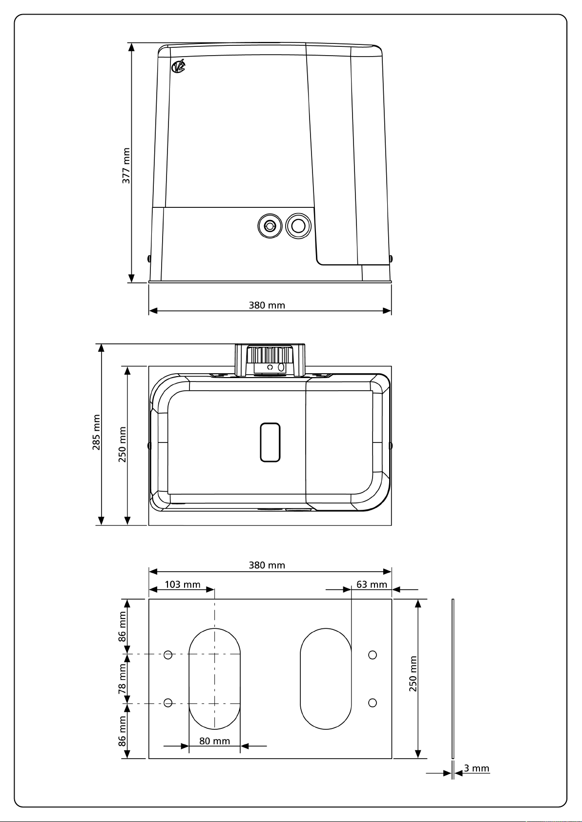
3.1 - POSIZIONAMENTO DEL MOTORE
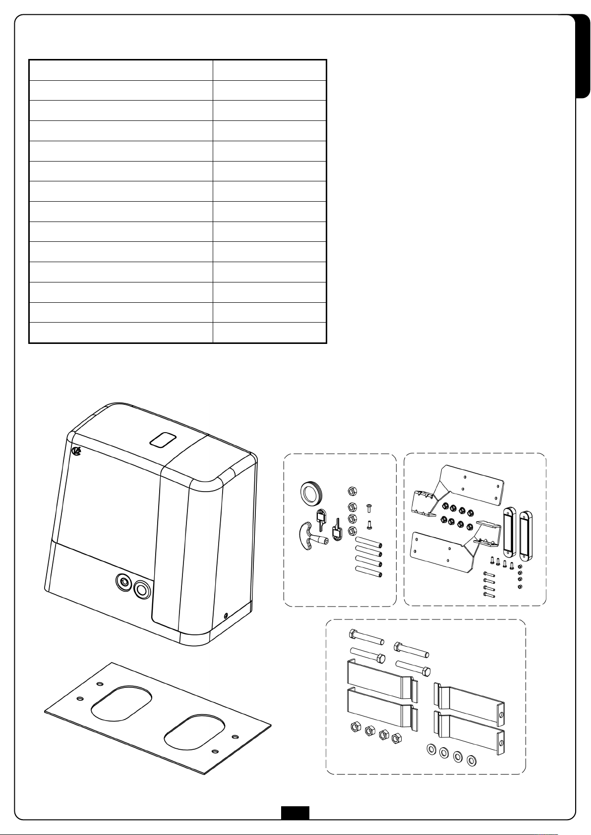
Per fissare FORTECO seguire attentamente le seguenti istruzioni:
1. Prevedere uno scavo di fondazione usando come riferimento le misure indicate in figura.
2. Predisporre uno o più tubi per il passaggio dei cavi elettrici.
3. Assemblare le 4 zanche sulla piastra di ancoraggio e fissarle tramite i 4 bulloni in dotazione.
6
Page 9
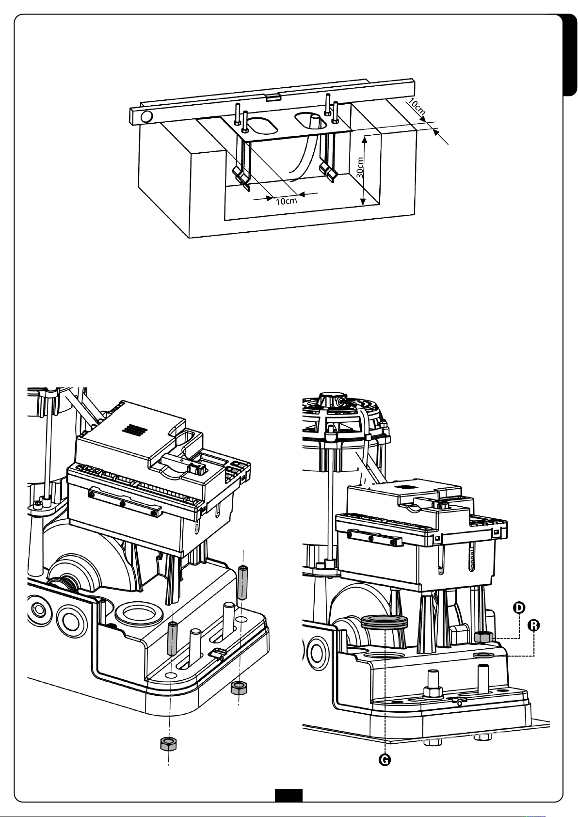
4. Effettuare la colata di calcestruzzo all’interno dello scavo e posizionare la piastra di fondazione.
m ATTENZIONE: verificare che la piastra sia perfettamente in bolla e parallela cancello.
5. Attendere la completa presa del calcestruzzo.
6. Svitare i 4 dadi che tengono la base unita alle zanche e posizionare il motore sulla piastra.
7. Inserire i 4 grani con i relativi dadi nelle apposite sedi. Regolare i 4 grani in modo che il motore sia perfettamente in bolla.
ITALIANO
8. Verificare che il motore sia perfettamente parallelo al cancello, quindi inserire le 4 rondelle R e avvitare leggermente i 4 dadi D
m ATTENZIONE: inserire la guarnizione G nel foro di passaggio cavi come da figura. Forare la guarnizione per far passare i cavi da
collegare alla centrale limitando le dimensioni dei fori al fine di evitare l’ingresso di insetti e altri piccoli animali.
7
Page 10
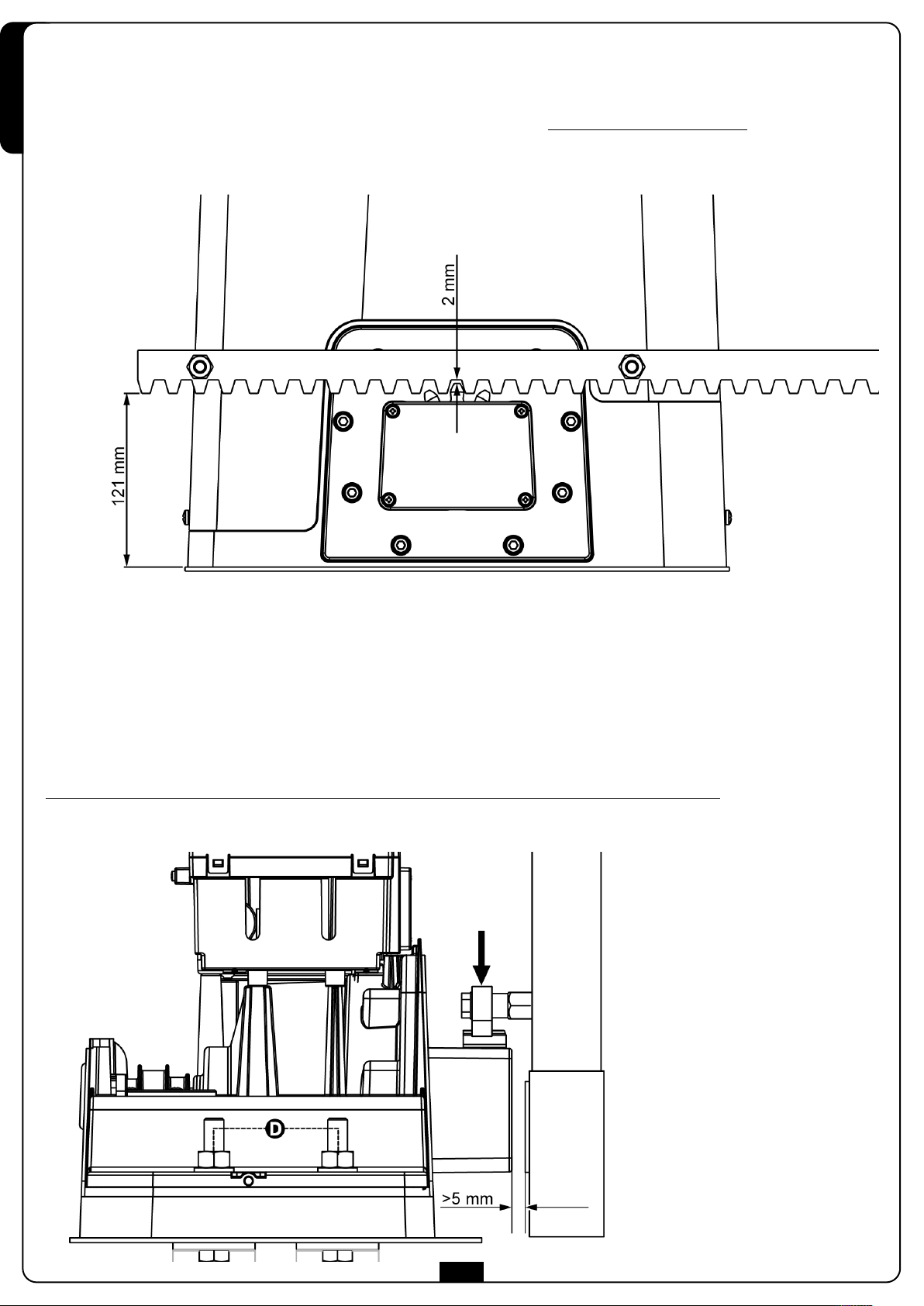
3.2 - MONTAGGIO DELLA CREMAGLIERA
Sbloccare il motore e posizionare il cancello in posizione totalmente aperto. Fissare tutti gli elementi della cremagliera al cancello facendo
attenzione di mantenerli alla stessa altezza rispetto al pignone motore.
ITALIANO
La cremagliera DEVE essere posizionata a 1 o 2 mm al di sopra del pignone motore su tutta la lunghezza del cancello
.
m ATTENZIONE: se il cancello è molto pesante si consiglia l’utilizzo di una cremagliera M4 22x22 (cod. 162324)
3.3 - FISSAGGIO DEL MOTORE
Verificare i seguenti punti:
1. Il motore deve essere in bolla e parallelo al cancello
2. La distanza tra pignone e cremagliera deve essere di 1 o 2 mm. Eventualmente regolare i 4 grani.
3. La cremagliera deve essere allineata al pignone del motore
4. La distanza minima tra l’ingombro massimo del cancello e il paramano del motore deve essere di almeno 5 mm
Verificate le condizioni sopra descritte procedere con il fissaggio dei 4 dadi D che ancorano il motore alla piastra.
8
Page 11
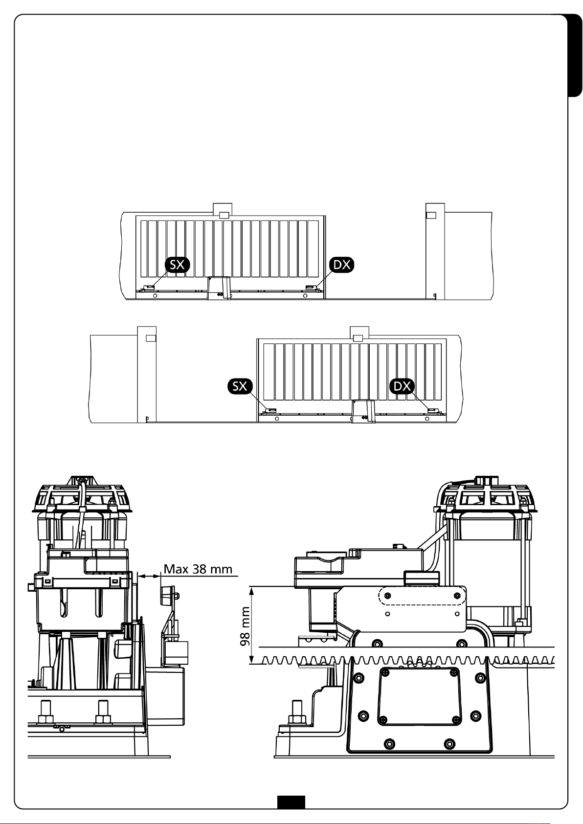
3.4 - INSTALLAZIONE DEI FINECORSA MAGNETICI
Installare la staffa porta magneti in dotazione sulla cremagliera in modo che nelle posizioni di massima apertura e di massima chiusura il
magnete rimanga posizionato in corrispondenza del sensore magnetico posto dietro la calotta (il più possibile vicino alla stessa).
I magneti in dotazione sono appositamente distinti da due colori:
MAGNETE BLU = FINECORSA DESTRO (DX)
MAGNETE ROSSO = FINECORSA SINISTRO (SX)
Il tipo di finecorsa (DESTRO/SINISTRO) dipende dalla posizione del finecorsa rispetto al motore, indipendentemente dal verso di apertura.
m ATTENZIONE: verificato il corretto funzionamento del sistema si consiglia di saldare le staffe finecorsa sulla cremagliera.
ITALIANO
9
Page 12
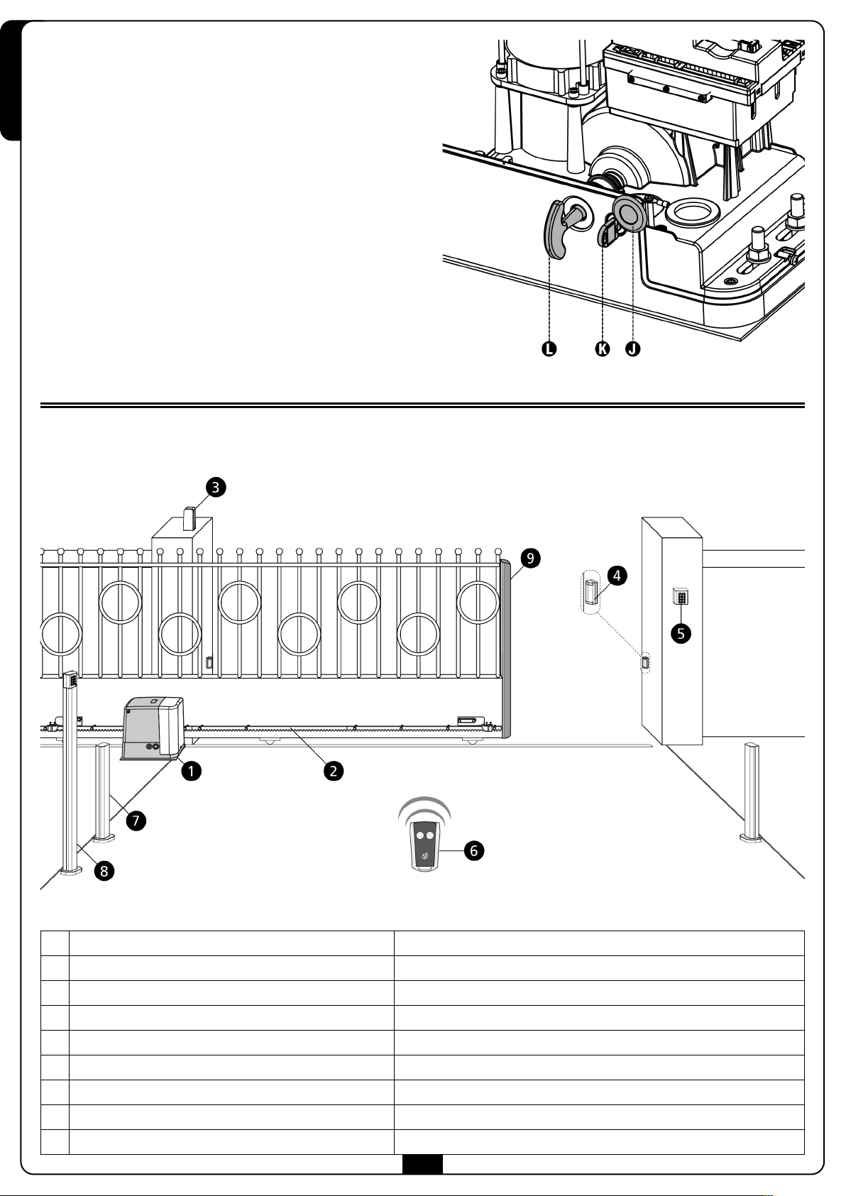
3.5 - SBLOCCO MOTORE
In caso di mancanza di corrente elettrica, il cancello può
essere sbloccato agendo sul motore:
ITALIANO
1. Aprire il copriserratura J presente sul lato frontale del motore.
2. Inserire la chiave K nella serratura e girare in senso orario per
aprire l’accesso allo sblocco posto a lato.
3. Inserire la chiave L nel foro e ruotare in senso orario fino a
finecorsa.
Per ripristinare l’automazione procedere come segue:
1. Ruotare la chiave L in senso antiorario fino a finecorsa ed
estrarla;
2. Ruotare la chiave K in senso antiorario in modo da chiudere
l’accesso allo sblocco ed estrarla.
. Coprire la serratura con lo sportello J.
3
3.6 - SCHEMA D’INSTALLAZIONE
Attuatore FORTECO cavo alimentazione 3 x 1,5 mm2(T100°C)
Cremagliera -
Lampeggiante con antenna integrata cavo alimentazione 2 x 1 mm2 - cavo antenna RG58
Fotocellule cavo 4 x 0,5 mm2(RX) - cavo 2 x 0,5 mm2(TX)
Selettore a chiave cavo 2 x 1 mm
Trasmettitore -
Fotocellule a colonna cavo 4 x 0,5 mm2(RX) - cavo 2 x 0,5 mm2(TX)
Selettore digitale via radio a colonna -
Costa di sicurezza (EN 12978) -
10
2
Page 13
4 - CENTRALE DI COMANDO
a PD20 è dotata di un display il quale permette, oltre che una
L
facile programmazione, il costante monitoraggio dello stato degli
ingressi; inoltre la struttura a menù permette una semplice
impostazione dei tempi di lavoro e delle logiche di
funzionamento.
Nel rispetto delle normative europee in materia di sicurezza
elettrica e compatibilità elettromagnetica (EN 60335-1,
N 50081-1 e EN 50082-1) è caratterizzata dal completo
E
isolamento elettrico tra la parte di circuito digitale e quella di
potenza.
Altre caratteristiche:
• Regolazione della velocità.
• Rilevamento degli ostacoli mediante monitoraggio della
corrente sul motore (amperometrica) o degli impulsi encoder.
• Apprendimento automatico dei tempi di lavoro.
• Test dei dispositivi di sicurezza (fotocellule, coste e triac) prima
di ogni apertura.
• Disattivazione degli ingressi di sicurezza tramite menu di
configurazione: non occorre ponticellare i morsetti relativi
alla sicurezza non installata, è sufficiente disabilitare la
funzione dal relativo menu.
• Funzionamento sincronizzato di due motori utilizzando il
modulo opzionale SYNCRO
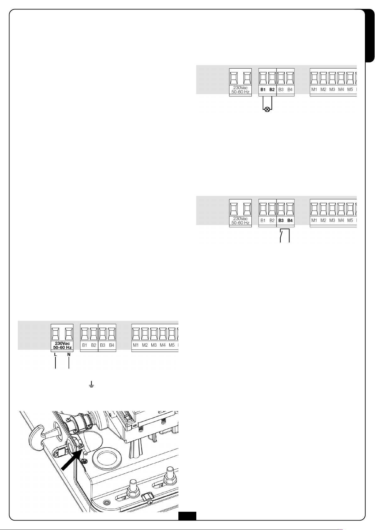
4.2 - LAMPEGGIATORE
La centrale PD20 prevede l’utilizzo di un lampeggiatore a
230V - 40W con intermittenza interna.
Collegare i cavi del lampeggiante ai morsetti B1 e B2 della
centrale.
4.3 - LUCI DI CORTESIA
Grazie all’uscita COURTESY LIGHT la centrale PD20 permette il
collegamento di un utilizzatore (ad esempio la luce di cortesia o
e luci da giardino), che viene comandato in modo automatico o
l
tramite azionamento dall’apposito tasto trasmettitore.
L’uscita COURTESY LIGHT consiste in un semplice contatto N.A. e
non fornisce nessun tipo di alimentazione.
Collegare i cavi ai morsetti B3 e B4.
ITALIANO
m ATTENZIONE: L’installazione della centrale, dei
dispositivi di sicurezza e degli accessori deve essere
eseguita con l’alimentazione scollegata.
4.1 - ALIMENTAZIONE
La centrale deve essere alimentata da una linea elettrica a
230V-50Hz protetta con interruttore magnetotermico
differenziale conforme alle normative di legge.
Collegare i cavi di alimentazione ai morsetti L e N della centrale
PD20.
Collegare a terra il motore per mezzo del morsetto
contrassegnato dal simbolo
Utilizzare il terminale ad occhiello in dotazione.
11
Page 14
4.4 - FOTOCELLULE
A seconda del morsetto a cui vengono collegate, la centrale
suddivide le fotocellule in due categorie:
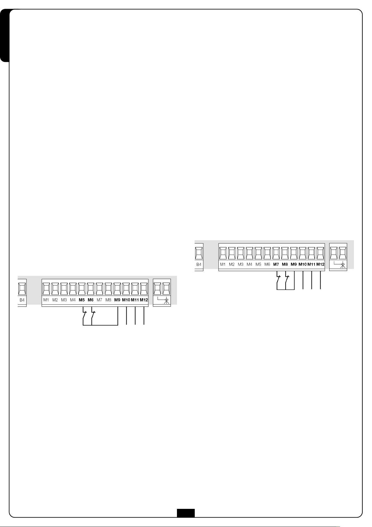
4.5 - COSTE SENSIBILI
A seconda del morsetto a cui vengono collegate, la centrale
suddivide le coste sensibili in due categorie:
ITALIANO
• Fotocellule di tipo 1: sono installate sul lato interno del
cancello e sono attive sia durante l’apertura sia durante la
chiusura. In caso di intervento delle fotocellule di tipo 1, la
centrale ferma il cancello: quando il fascio viene liberato la
centrale apre completamente il cancello.
m ATTENZIONE: le fotocellule di tipo 1 devono essere
installate in modo da coprire completamente l'area di apertura
del cancello.
• Fotocellule di tipo 2: sono installate sul lato esterno del
cancello e sono attive solo durante la chiusura. In caso di
intervento delle fotocellule di tipo 2, la centrale riapre
immediatamente il cancello, senza attendere il disimpegno.
La centrale PD20 fornisce un’alimentazione a 24VAC per le
fotocellule e può eseguire un test del loro funzionamento prima
di iniziare l’apertura del cancello. I morsetti di alimentazione per
le fotocellule sono protetti da un fusibile elettronico che
interrompe la corrente in caso di sovraccarico.
• Collegare i cavi di alimentazione dei trasmettitori delle
fotocellule tra i morsetti M11 e M12 della centrale.
• Collegare i cavi di alimentazione dei ricevitori delle
fotocellule tra i morsetti M10 e M11 della centrale.
• Collegare l’uscita N.C. dei ricevitori delle fotocellule di tipo 1
tra i morsetti M5 e M9 della centrale e l’uscita dei ricevitori
delle fotocellule di tipo 2 tra i morsetti M6 e M9 della
centrale.
Usare le uscite con contatto normalmente chiuso.
• Coste di tipo 1 : in caso di intervento delle coste di tipo 1
durante l’apertura del cancello, la centrale fa richiudere per
3 secondi, quindi va in blocco; in caso di intervento delle coste
di tipo 1 durante la chiusura del cancello, la centrale va
immediatamente in blocco. La direzione di azionamento
del cancello al successivo comando di START o START
PEDONALE dipende dal parametro STOP (inverte o prosegue
il moto). Se l’ingresso di STOP è disabilitato, il comando fa
riprendere il moto nella stessa direzione.
• Coste di tipo 2 : in caso di intervento delle coste di tipo 2
durante l’apertura del cancello, la centrale va immediatamente
in blocco; in caso di intervento delle coste di tipo 2 durante la
hiusura del cancello, la centrale fa riaprire per 3 secondi,
c
quindi va in blocco. La direzione di azionamento del cancello
al successivo comando di START o START PEDONALE dipende
dal parametro STOP (inverte o prosegue il moto).
Se l’ingresso di STOP è disabilitato, il comando fa riprendere il
moto nella stessa direzione.
Entrambi gli ingressi sono in grado di gestire sia la costa classica
con contatto normalmente chiuso sia la costa a gomma
conduttiva con resistenza nominale 8,2 kohm.
Collegare i cavi delle coste di tipo 1 tra i morsetti M7 e M9 della
centrale.
Collegare i cavi delle coste di tipo 2 tra i morsetti M8 e M9 della
centrale.
m ATTENZIONE:
• Se vengono installate più coppie di fotocellule dello stesso
tipo, le loro uscite devono essere collegate in serie.
• Se vengono installate delle fotocellule a riflessione,
l'alimentazione deve essere collegata ai morsetti M11 e M12
della centrale per effettuare il test di funzionamento.
Per soddisfare i requisiti della normativa EN12978 è necessario
installare coste sensibili a gomma conduttiva; le coste sensibili
con contatto normalmente chiuso devono essere dotate di una
centralina che ne verifichi costantemente la corretta funzionalità.
Se si utilizzano centraline che hanno la possibilità di eseguire il
test mediante interruzione dell’alimentazione, collegare i cavi di
alimentazione della centralina tra i morsetti M11 e M12 della
PD20. In caso contrario collegarli tra i morsetti M10 e M11.
m ATTENZIONE:
• Se si utilizzano più coste con contatto normalmente chiuso,
le uscite devono essere collegate in serie.
• Se si utilizzano più coste a gomma conduttiva, le uscite
devono essere collegate in cascata e solo l’ultima deve
essere terminata sulla resistenza nominale.
12
Page 15
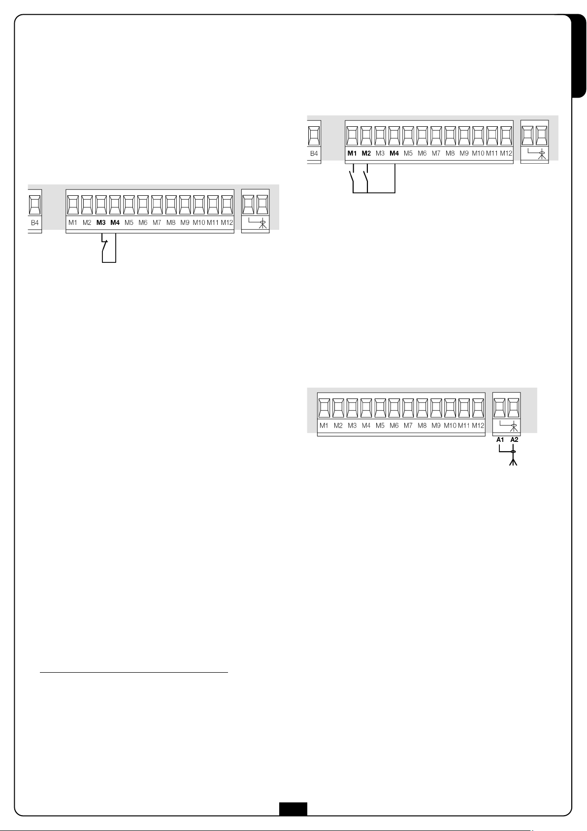
4.6 - STOP
Per una maggiore sicurezza è possibile installare un interruttore
che quando azionato provoca il blocco immediato del cancello.
L’interruttore deve avere un contatto normalmente chiuso, che si
apre in caso di azionamento.
Se l’interruttore di stop viene azionato mentre il cancello è aperto
viene sempre disabilitata la funzione di richiusura
automatica; per richiudere il cancello occorre dare un comando
di start (se la funzione di start in pausa è disabilitata, viene
temporaneamente riabilitata per consentire lo sblocco del
cancello).
Collegare i cavi dell’interruttore di stop tra i morsetti M3 e M4
della centrale.
La funzione dell’interruttore di stop può essere anche attivata
mediante un telecomando memorizzato sul canale 3 (vedere le
istruzioni del ricevitore MR1).
In tutte le modalità, gli ingressi devono essere collegati a
dispositivi con contatto normalmente aperto.
Collegare i cavi del dispositivo che comanda il primo ingresso tra
i morsetti M1 e M4 della centrale.
Collegare i cavi del dispositivo che comanda il secondo
ingresso tra i morsetti M2 e M4 della centrale.
La funzione associata al primo ingresso può essere attivata anche
h
premendo il tasto
mediante un telecomando memorizzato sul canale 1 (vedere le
istruzioni del ricevitore MR1).
La funzione associata al secondo ingresso può essere attivata
anche premendo il tasto
programmazione, o mediante un telecomando memorizzato sul
canale 2 (vedere le istruzioni del ricevitore MR1).
al di fuori del menu di programmazione, o
i
al di fuori del menu di
ITALIANO
4.7 - INGRESSI DI ATTIVAZIONE
La centrale PD20 dispone di due ingressi di attivazione, la cui
funzione dipende dalla modalità di funzionamento programmata
(Vedere la voce Strt del menu di programmazione):
• Modalità standard: un comando sul primo ingresso
provoca l’apertura totale del cancello (start); un comando
sul secondo ingresso provoca l’apertura parziale del
cancello (start pedonale).
• Modalità Apri/Chiudi: un comando sul primo ingresso
comanda sempre l’apertura e un comando sul secondo
ingresso comanda sempre la chiusura.
Il comando è di tipo impulsivo, cioè un impulso provoca la
totale apertura o chiusura del cancello.
• Modalità Uomo Presente: un comando sul primo ingresso
comanda sempre l’apertura e un comando sul secondo
ingresso comanda sempre la chiusura.
Il comando è di tipo monostabile, cioè il cancello viene aperto
o chiuso fintanto che il contatto è chiuso e si arresta
immediatamente se il contatto viene aperto.
• Modalità Orologio: è analoga alla modalità standard, ma il
cancello rimane aperto fintanto che il contatto rimane chiuso
sull’ingresso; quando il contatto viene aperto inizia il
conteggio del tempo di pausa, scaduto il quale il cancello
viene richiuso.
Questa funzione permette di programmare nell’arco della
giornata le fasce orarie di apertura del cancello, utilizzando
un timer esterno.
E’ indispensabile abilitare la richiusura automatica
NOTA: se il parametro P.APP = 0 il timer collegato sul
secondo ingresso non provoca l’apertura, ma permette di
inibire la chiusura automatica negli orari stabiliti.
.
4.8 - ANTENNA
Si consiglia di utilizzare l'antenna esterna modello ANS433
per garantire la massima portata radio.
Collegare il polo caldo dell’antenna al morsetto A2 della
centrale e la calza al morsetto A1
13
Page 16
4.9 - RICEVITORE AD INNESTO
La centrale PD20 è predisposta per l'innesto di un ricevitore della
serie MR1 con architettura super-eterodina ad elevata sensibilità.
ITALIANO
m ATTENZIONE: Prima di eseguire le seguenti operazioni
disalimentare la centrale di comando. Porre la massima
attenzione al verso di innesto dei moduli estraibili.
Il modulo ricevitore MR1 ha a disposizione 4 canali ad ognuno
dei quali è associato un comando della centrale PD20:
• CANALE 1
• CANALE 2
• CANALE 3 쩚쩛STOP
• CANALE 4 쩚쩛LUCI DI CORTESIA
NOTA: Per la programmazione dei 4 canali e delle logiche
di funzionamento leggere attentamente le istruzioni
allegate al ricevitore MR1.
쩚쩛
START
쩚쩛
START PEDONALE
4.10 - INTERFACCIA ADI
a centrale di comando è dotata di interfaccia ADI (Additional
L
Devices Interface), che permette il collegamento con una serie di
moduli opzionali della linea V2.
are riferimento al catalogo V2 per vedere quali moduli opzionali
F
con interfaccia ADI sono disponibili per questa centrale.
TTENZIONE: Per l'installazione dei moduli opzionali,
m A
leggere attentamente le istruzioni allegate ai singoli
moduli.
Per alcuni dispositivi è possibile configurare il modo con cui si
interfacciano con la centrale, inoltre è necessario abilitare
l’interfaccia per fare in modo che la centrale tenga conto delle
egnalazioni che arrivano dal dispositivo ADI.
s
Far riferimento al menù di programmazione i.ADi per abilitare
l’interfaccia ADI e accedere al menù di configurazione del
dispositivo.
I dispositivi ADI utilizzano il display della centrale per effettuare
segnalazioni di allarme o visualizzare la configurazione della
centrale di comando.
NOTA: Se l’interfaccia ADI non è abilitata (nessun
dispositivo collegato), i segmenti restano spenti.
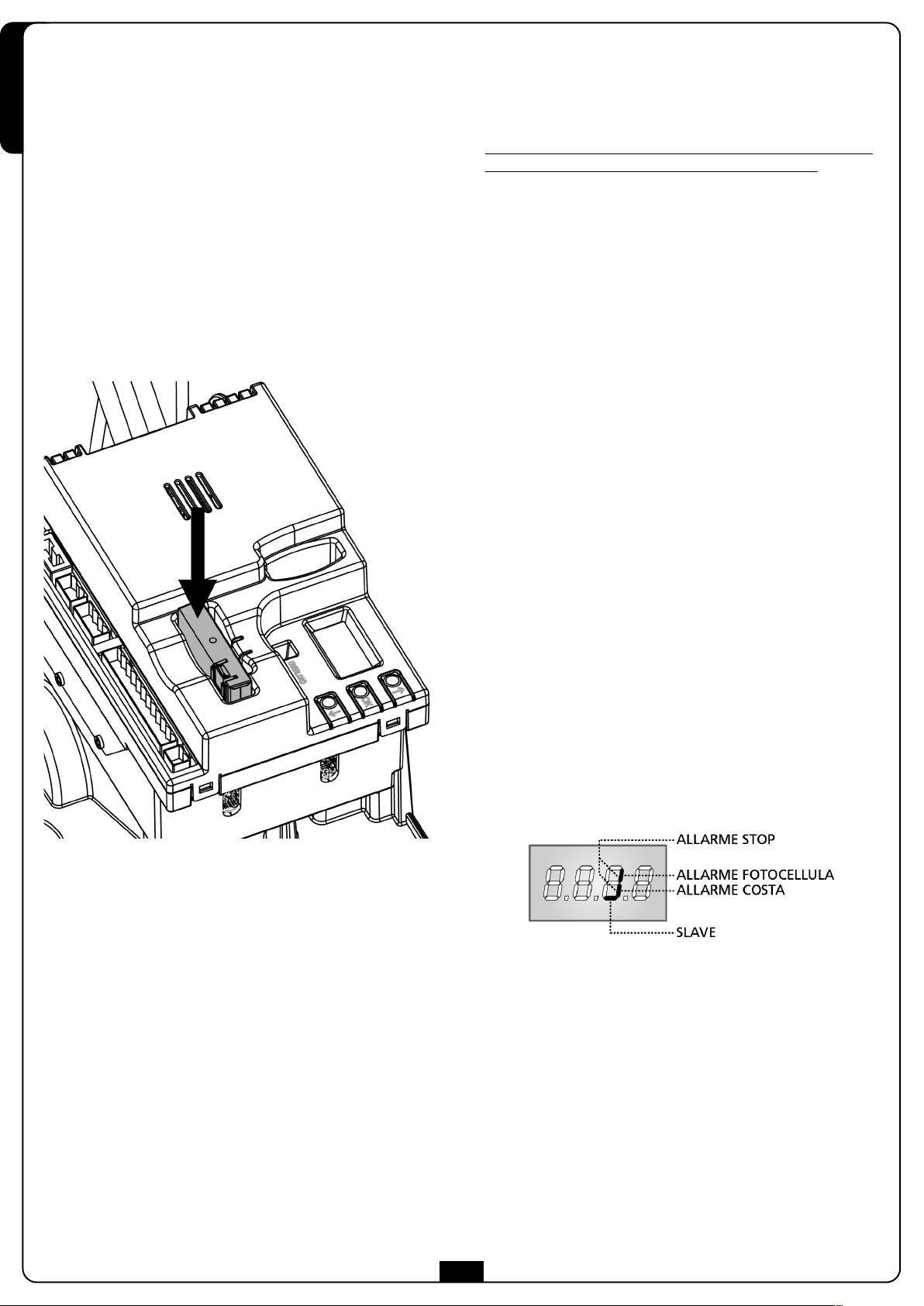
Il dispositivo collegato sull’interfaccia Adi è in grado di segnalare
alla centrale tre tipi di allarme, che vengono visualizzate sul
display della centrale nel modo seguente:
• ALLARME FOTOCELLULA - il segmento in alto si accende:
il cancello si ferma, quando l’allarme cessa riparte in apertura.
• ALLARME COSTA - il segmento in basso si accende:
il cancello inverte il movimento per 3 secondi.
• ALLARME STOP - entrambi i segmenti lampeggiano:
il cancello si ferma e non può ripartire finchè non cessa
l’allarme.
• SLAVE - segmento acceso fisso: viene utilizzato dal modulo
opzionale SYNCRO per indicare quando la centrale è
configurata come SLAVE.
14
Page 17
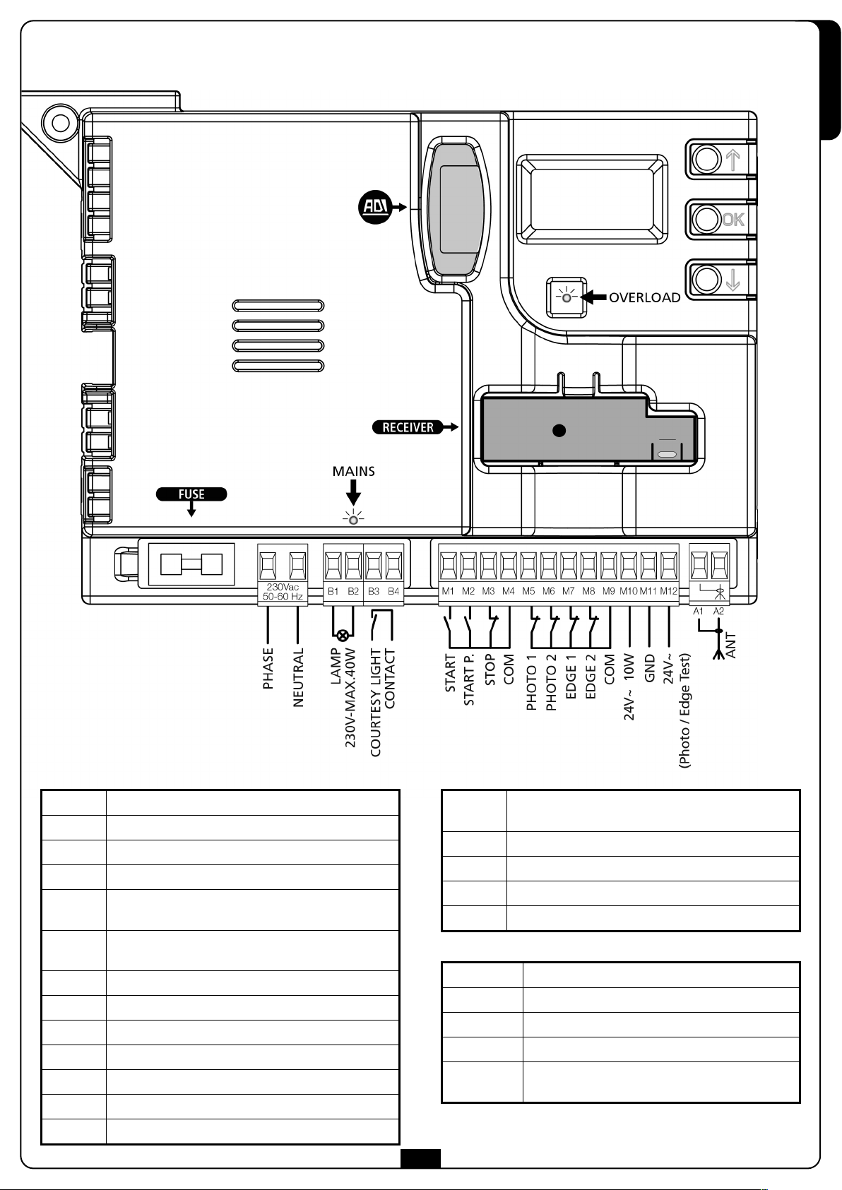
.11 - COLLEGAMENTI ELETTRICI
4
ITALIANO
PHASE Fase alimentazione 230VAC
NEUTRAL Neutro alimentazione 230VAC
B1-B2 Lampeggiante 230VAC - 40W
B3-B4 Luci di cortesia
M1
M2
M3 Comando di STOP. Contatto N.C.
M4 Comune (-)
M5 Fotocellula di tipo 1. Contatto N.C.
M6 Fotocellula di tipo 2. Contatto N.C.
M7 Coste di tipo 1. Contatto N.C.
M8 Coste di tipo 2. Contatto N.C.
M9 Comune (-)
Comando di apertura per il collegamento di
dispositivi tradizionali con contatto N.A.
Comando di apertura pedonale per il collegamento
di dispositivi tradizionali con contatto N.A.
M10
M11 Comune alimentazione accessori (-)
M12 Alimentazione TX fotocellule per Test funzionale
A1 Schermatura antenna
A2 Centrale antenna
ADI Interfaccia ADI
RECEIVER Ricevitore ad innesto
FUSE 8A
MAINS Segnala che la centrale è alimentata
OVERLOAD
15
Uscita alimentazione 24VAC per fotocellule ed altri
accessori
Segnala un sovraccarico sull’alimentazione
degli accessori
Page 18
5 - PANNELLO DI CONTROLLO
5.1 - DISPLAY
uando viene attivata l'alimentazione, la centrale verifica il
Q
ITALIANO
corretto funzionamento del display accendendo tutti i segmenti
.8.8.8
er 1,5 sec.
p
versione del firmware, ad esempio Pr I.0.
Al termine di questo test viene visualizzato il pannello di
controllo:
8
Nei successivi 1,5 sec. viene visualizzata la
.
5.2 - USO DEI TASTI PER LA
PROGRAMMAZIONE
La programmazione delle funzioni e dei tempi della centrale
viene eseguita tramite un apposito menù di configurazione,
accessibile ed esplorabile tramite i 3 tasti h, ie OK posti di
fianco al display della centrale.
ATTENZIONE: Al di fuori del menu di configurazione,
h
premendo il tasto
il tasto
Di seguito una tabella che descrive le funzioni dei tasti:
i
si attiva il comando START PEDONALE.
remere e rilasciare il tasto OK
P
Mantenere la pressione sul tasto OK per 2 secondi
Rilasciare il tasto OK
si attiva il comando START, premendo
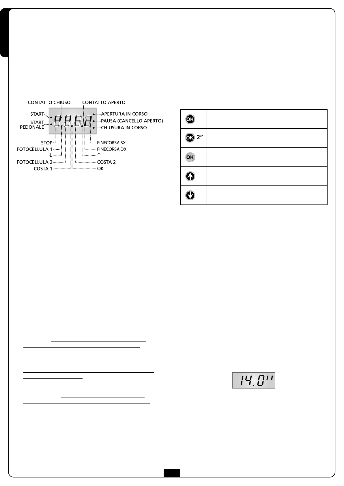
Il pannello di controllo (in stand-by) indica lo stato fisico dei
contatti alla morsettiera e dei tasti di programmazione: se è
acceso il segmento verticale in alto, il contatto è chiuso; se è
acceso il segmento verticale in basso, il contatto è aperto (il
disegno sopra illustra il caso in cui gli ingressi: PHOTO1,
PHOTO2, EDGE1, EDGE2 e STOP sono stati tutti collegati
correttamente).
NOTA: se viene utilizzato un modulo ADI sul display
potrebbero comparire altri segmenti, consultare il
paragrafo dedicato “INTERFACCIA ADI”
I punti tra le cifre del display indicano lo stato lo stato dei
pulsanti di programmazione: quando si preme un tasto il relativo
punto si
accende.
Le frecce a sinistra del display indicano lo stato degli ingressi di
start. Le frecce si accendono quando il relativo ingresso viene
chiuso.
Le frecce a destra del display indicano lo stato del cancello:
• La freccia più in alto si accende quando il cancello è in fase
di apertura. Se lampeggia indica che l'apertura è stata
causata dall'intervento di un dispositivo di sicurezza (costa
o rilevatore di ostacoli).
• La freccia centrale indica che il cancello è in pausa.
Se lampeggia significa che è attivo il conteggio del tempo
per la chiusura automatica.
Premere e rilasciare il tasto
Premere e rilasciare il tasto
Esistono tre tipologie di voci di menu:
• Menu di funzione
• Menu di tempo
• Menu di valore
Impostazione dei menu di funzione
I menu di funzione permettono di scegliere una funzione tra un
gruppo di possibili opzioni. Quando si entra in un menu di
funzione viene visualizzata l’opzione attualmente attiva;
mediante i tasti ie hè possibile scorrere le opzioni
disponibili. Premendo il tasto OK si attiva l’opzione
visualizzata e si ritorna al menu di configurazione.
Impostazione dei menu di tempo
I menu di tempo permettono di impostare la durata di una
funzione. Quando si entra in un menu di tempo viene
visualizzato il valore attualmente impostato; la modalità di
visualizzazione dipende dal valore impostato:
• I tempi inferiori al minuto vengono visualizzati in questo
formato:
h
i
• La freccia più in basso si accende quando il cancello è in
fase di chiusura. Se lampeggia indica che la chiusura è
stata causata dall'intervento di un dispositivo di sicurezza
(costa o rilevatore di ostacoli).
h
Ogni pressione del tasto
mezzo secondo; ogni pressione del tasto ilo fa diminuire di
mezzo secondo.
16
fa aumentare il tempo impostato di
Page 19
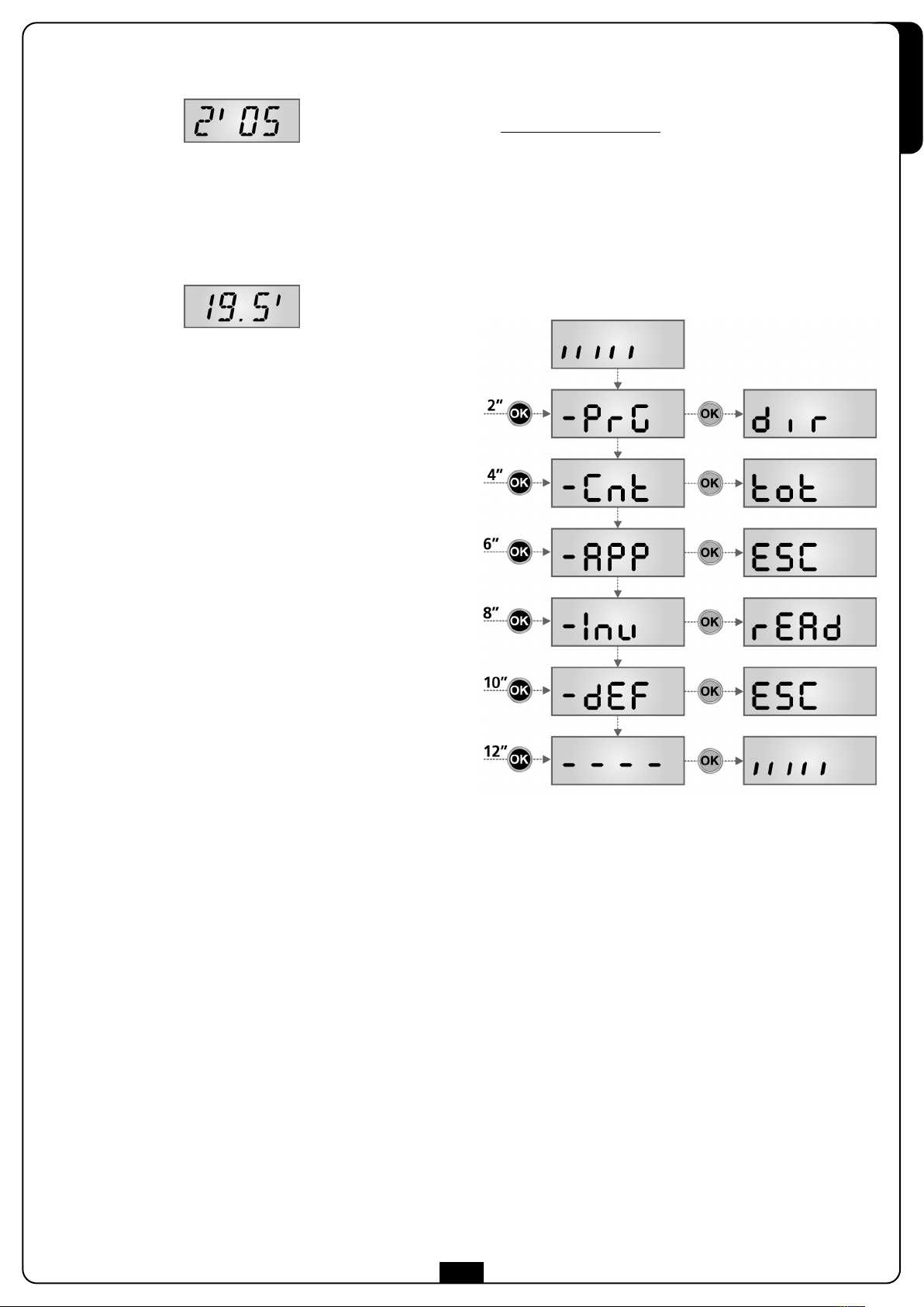
• I tempi compresi tra 1 e 10 minuti vengono visualizzati in
questo formato:
h
Ogni pressione del tasto
secondi; ogni pressione del tasto
• I tempi superiori ai 10 minuti vengono visualizzati in questo
formato:
Ogni pressione del tasto
mezzo minuto; ogni pressione del tasto
mezzo minuto.
Tenendo premuto il tasto
valore di tempo, fino a raggiungere il massimo previsto per
questa voce. Analogamente tenendo premuto il tasto
diminuire velocemente il tempo fino a raggiungere il
0.0 “
valore
In alcuni casi l’impostazione del valore 0 equivale alla
disabilitazione della funzione: in questo caso invece del valore
fa aumentare il tempo impostato di 5
i
lo fa diminuire di 5 secondi.
h
fa aumentare il tempo impostato di
i
lo fa diminuire di
h
si può aumentare velocemente il
i
si può
0.0 “ viene visualizzato no.
Premendo il tasto OK si conferma il valore visualizzato e si ritorna
al menu di configurazione.
6 - ACCESSO ALLE IMPOSTAZIONI
DELLA CENTRALE
1. Tenere premuto il tasto OK fino a quando il display visualizza il
menù desiderato
2. Rilasciare il tasto OK: il display visualizza la prima voce
del sottomenù
-PrG Programmazione della centrale
-Cnt Contatore di cicli
-APP Autoapprendimento di tempi e forze
-Inv Test di funzionamento della scheda inverter
-dEF C
aricamento dei parametri di default
ITALIANO
Impostazione dei menu di valore
I menu di valore sono analoghi ai menu di tempo, ma il valore
impostato è un numero qualsiasi.
h
Tenendo premuto il tasto
diminuisce lentamente.
Premendo il tasto OK si conferma il valore visualizzato e si ritorna
al menu di configurazione.
o il tasto iil valore aumenta o
m ATTENZIONE: se non si effettua alcuna operazione per
più di un minuto la centrale esce dalla modalità di
programmazione senza salvare le impostazioni e le
modifiche effettuate vengono perse.
17
Page 20
7 - CONFIGURAZIONE VELOCE
In questo paragrafo viene illustrata una procedura veloce per configurare la centrale e metterla immediatamente in opera.
i consiglia di seguire inizialmente queste istruzioni per verificare velocemente il corretto funzionamento della centrale, del
S
ITALIANO
motore e degli accessori.
1. Richiamare la configurazione di default: vedi paragrafo “CARICAMENTO DEI PARAMETRI DI DEFAULT”.
2. Impostare le voci StoP, Fot1, Fot2, CoS1, CoS2 in base alle sicurezze installate sul cancello
(vedi paragrafo “CONFIGURAZIONE DELLA CENTRALE”).
. Avviare il ciclo di autoapprendimento: vedi paragrafo “AUTOAPPRENDIMENTO DEI TEMPI DI LAVORO”
3
4. Verificare il corretto funzionamento dell’automazione e se necessario modificare la configurazione dei parametri desiderati.
Per la posizione delle voci all’interno del menu e per le opzioni disponibili per ciascuna voce, fare riferimento al paragrafo
CONFIGURAZIONE DELLA CENTRALE”.
“
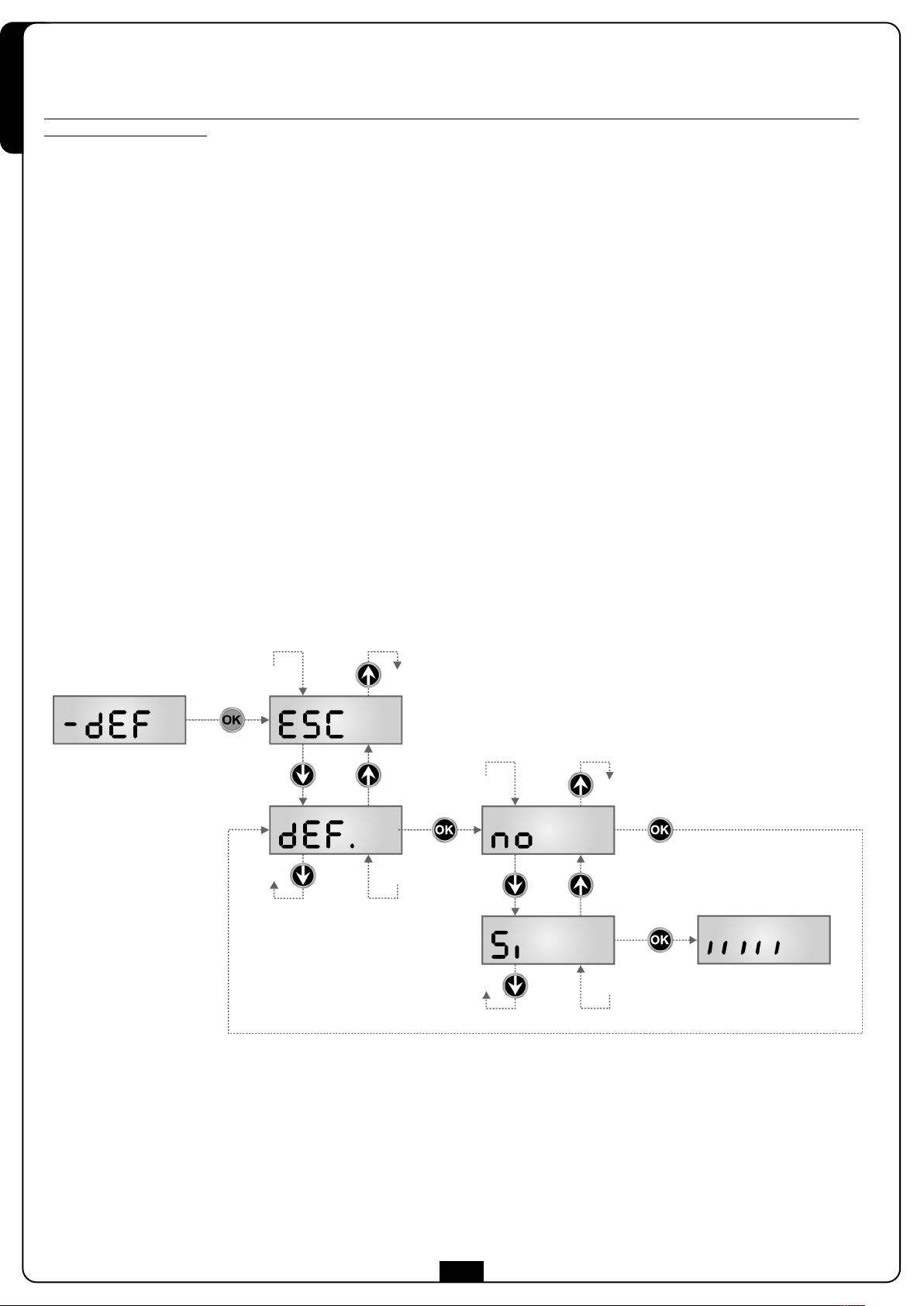
8 - CARICAMENTO DEI PARAMETRI DI DEFAULT
In caso di necessità, è possibile riportare tutti i parametri al loro valore standard o di default (vedere la tabella riassuntiva finale).
m ATTENZIONE: Questa procedura comporta la perdita di tutti i parametri personalizzati, e perciò è stata inserita all'esterno
del menu di configurazione, per minimizzare la probabilità che venga eseguita per sbaglio.
1. Mantenere premuto il tasto OK fino a quando il display visualizza
2. Rilasciare il tasto OK: il display visualizza ESC (premere il tasto OK solo se si desidera uscire da questo menù)
3. Premere il tasto
4. Premere il tasto OK: il display visualizza no
5. Premere il tasto i: il display visualizza Si
6. Premere il tasto OK: tutti i parametri vengono riscritti con il loro valore di default (vedi capitolo 13.2), la centrale esce dalla
programmazione e il display visualizza il pannello di controllo.
i
: il display visualizza dEF
-dEF
18
Page 21
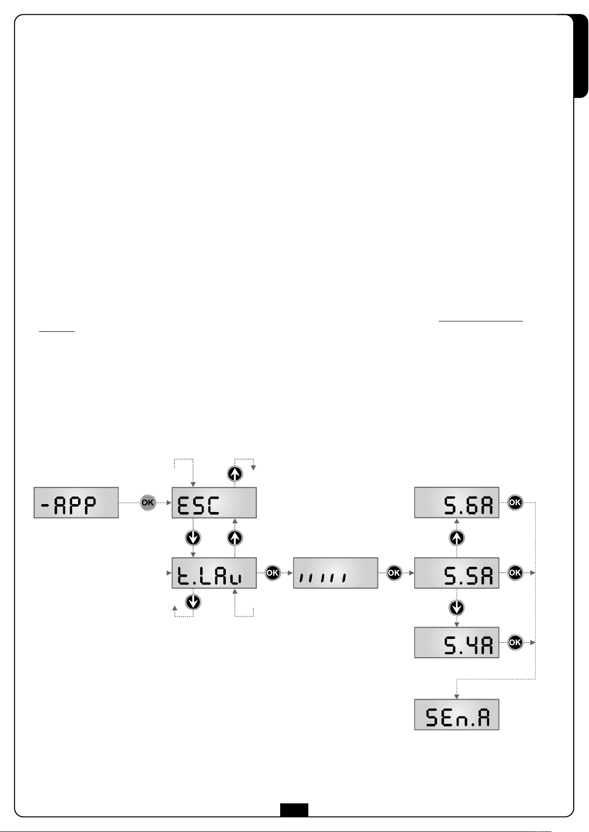
9 - AUTOAPPRENDIMENTO DEI TEMPI DI LAVORO
Questo menù permette di apprendere in modo automatico i tempi necessari per aprire e chiudere il cancello.
urante questa fase la centrale memorizza anche le forze necessarie per aprire e chiudere il cancello: questi valori verranno
D
utilizzati attivando il sensore di ostacoli.
m ATTENZIONE: per eseguire la procedura di autoapprendimento è necessario disabilitare l’interfaccia ADI tramite
il menù i.Adi . Se ci sono delle sicurezze che vengono controllate tramite il modulo ADI durante la fase di autoapprendimento
non saranno attive.
m ATTENZIONE: prima di procedere assicurarsi di aver installato nella posizione corretta i finecorsa.
1. Mantenere premuto il tasto OK fino a quando il display visualizza -APP
2. Rilasciare il tasto OK: il display visualizza ESC (premere il tasto OK solo se si desidera uscire da questo menù)
3. Premere il tasto
4. Premere il tasto OK per avviare il ciclo di autoapprendimento: il display visualizza il pannello di controllo e inizia la procedura di
autoapprendimento tempi.
.1 Il cancello viene attivato in chiusura fino a battuta o al raggiungimento del finecorsa di chiusura.
4
4.2 Il cancello viene attivato in apertura fino a battuta o al raggiungimento del finecorsa di apertura.
4.3 Il cancello viene attivato in chiusura fino a battuta o al raggiungimento del finecorsa di chiusura.
i
: il display visualizza t.LAv
m ATTENZIONE: durante la fase di autoapprendimento dei tempi il motore si muove a velocità ridotta.
5. Se il sensore ostacoli AMPEROMETRICO è stato abilitato, sul display viene visualizzato il valore suggerito per la soglia del sensore.
Se non viene eseguita nessuna operazione per 20 secondi la centrale esce dalla fase di programmazione senza salvare il valore
suggerito.
ITALIANO
he i
6. Il valore suggerito può essere modificato con i tasti
visualizza SEn.A
i
7. Tenere premuto il tasto
OK per uscire dalla programmazione memorizzando il valore dei sensori.
fino a quando il display visualizza FinE, quindi premere il tasto OK, selezionare la voce Si e premere il tasto
, premendo il tasto OK viene confermato il valore visualizzato e il display
m ATTENZIONE: Se si lascia che la centrale esca dalla programmazione per time out (1 minuto) il sensore di ostacoli
ritorna al valore che era impostato prima di eseguire l’autoapprendimento (secondo i valori di default il sensore è
disabilitato). Le posizioni dei finecorsa invece vengono sempre memorizzate.
Esempio
19
Page 22
10 - FUNZIONAMENTO DEL SENSORE DI OSTACOLI
La centrale PD20 è dotata di due sistemi indipendenti che permettono di rilevare se il movimento del cancello è impedito da un ostacolo.
ITALIANO
Il primo sistema
di un ostacolo.
si basa sulla misura della corrente assorbita dal motore: un improvviso aumento dell’assorbimento indica la presenza
l secondo sistema
I
di un ostacolo.
i basa sulla misura della velocità di rotazione del motore: un abbassamento della velocità indica la presenza
s
m ATTENZIONE:
• Il sensore amperometrico è disabilito per default e deve essere abilitato tramite la voce di menù SEn.A
• Il sensore di velocità è abilitato per default e la sua sensibilità può essere regolata con la voce di menù SEn.V
I due sistemi funzionano sia quando il cancello si muove a velocità normale sia quando è in fase di rallentamento.
Quando interviene un sensore il cancello si ferma e viene comandato in direzione inversa per 3 secondi per liberare l’ostacolo.
Il successivo comando di Start fa riprendere il movimento nella direzione precedente.
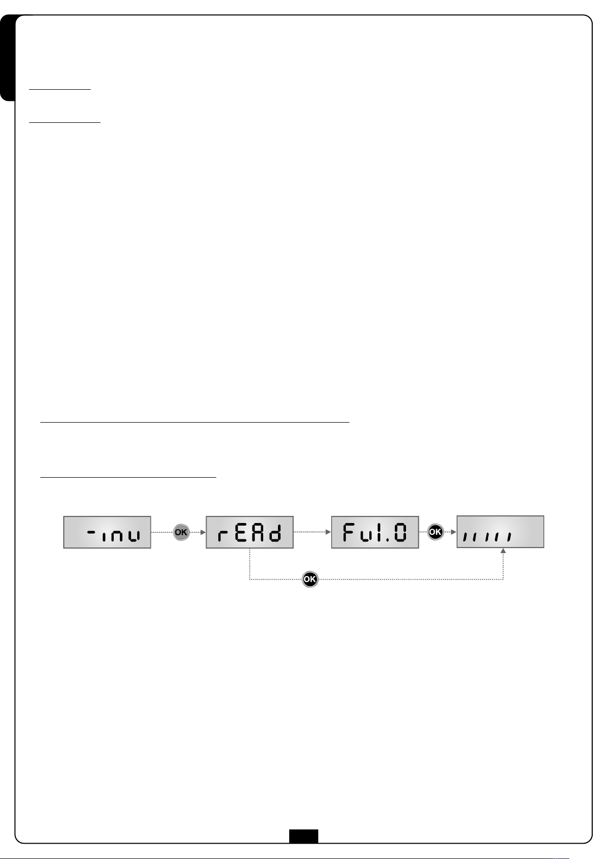
11 - TEST DI FUNZIONAMENTO DELLA SCHEDA INVERTER
Questo menù permette di effettuare un test di funzionamento sulla scheda INVERTER.
1. Mantenere premuto il tasto OK fino a quando il display visualizza -inv
2. Rilasciare il tasto OK: il display visualizza rEAd
3. Se la scheda INVERTER funziona correttamente dopo alcuni secondi il display visualizza la versione firmware della scheda.
he i
NOTA: in questa fase tramite i tasti
Consultare questi menù solo su indicazioni del servizio di assistenza tecnica V2.
è possibile accedere a dei menù di diagnostica.
4. Premere il tasto OK: la centrale esce dalla programmazione e il display visualizza il pannello di controllo
5. Se il display continua a visualizzare rEAd significa che la scheda INVERTER non funziona correttamente
Consultare il servizio di assistenza tecnica V2
.
20
Page 23
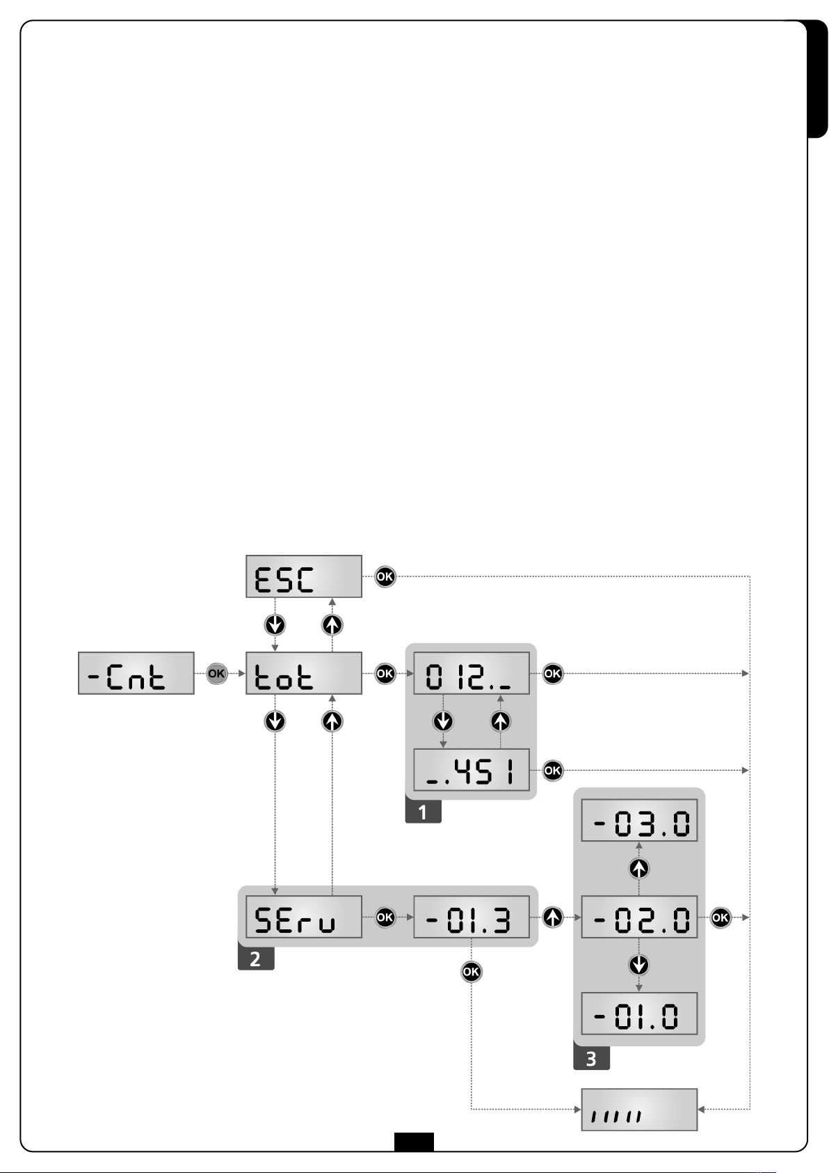
12 - LETTURA DEL CONTATORE DI CICLI
a centrale PD20 tiene il conto dei cicli di apertura del cancello completati e, se richiesto, segnala la necessità di manutenzione dopo un
L
numero prefissato di manovre.
Sono disponibili due contatori:
ot
• Totalizzatore non azzerabile dei cicli di apertura completati (opzione t
• Contatore a scalare dei cicli che mancano al prossimo intervento di manutenzione (opzione
Questo secondo contatore può essere programmato con il valore desiderato.
Lo schema che segue illustra la procedura per leggere il totalizzatore, leggere il numero di cicli mancanti al prossimo intervento di
anutenzione e programmare il numero di cicli mancanti al prossimo intervento di manutenzione (nell’esempio la centrale ha completato
m
12451 cicli e mancano 1300 cicli al prossimo intervento.
della voce C
ont
)
SErv della voce Cont).
ITALIANO
L’area 1 rappresenta la lettura del conteggio totale di cicli completati: con i tasti
o delle unità.
L’area 2 rappresenta la lettura del numero di cicli mancanti al prossimo intervento di manutenzione: il valore è arrotondato alle centinaia.
L’area 3 rappresenta l’impostazione di quest’ultimo contatore: alla prima pressione del tasto
arrotondato alle migliaia, ogni pressione successiva fa aumentare o diminuire l’impostazione di 1000 unità. Il conteggio precedentemente
visualizzato viene perduto.
he i
è possibile alternare la visualizzazione delle migliaia
ho i
il valore attuale del contatore viene
Segnalazione della necessità di manutenzione
Quando il contatore dei cicli mancanti al prossimo intervento di manutenzione arriva a zero, la centrale segnala la richiesta di
manutenzione mediante un prelampeggio supplementare di 5 secondi.
La segnalazione viene ripetuta all’inizio di ogni ciclo di apertura, finchè l’installatore non accede al menu di lettura e impostazione del
contatore, programmando eventualmente il numero di cicli dopo il quale sarà nuovamente richiesta la manutenzione.
Se non viene impostato un nuovo valore (cioè il contatore viene lasciato a zero), la funzione di segnalazione della richiesta di
manutenzione è disabilitata e la segnalazione non viene più ripetuta.
m ATTENZIONE: le operazioni di manutenzione devono essere eseguite esclusivamente da personale qualificato.
21
Page 24
13 - PROGRAMMAZIONE DELLA CENTRALE
Il menu di programmazione -PrG consiste in una lista di voci configurabili; la sigla che compare sul display indica la voce attualmente
i
selezionata. Premendo il tasto
visualizza il valore attuale della voce selezionata e si può eventualmente modificarlo.
ITALIANO
L'ultima voce di menu (FinE) permette di memorizzare le modifiche effettuate e tornare al funzionamento normale della centrale.
Per non perdere la propria configurazione è obbligatorio uscire dalla modalità di programmazione attraverso questa voce del menu.
si passa alla voce successiva; premendo il tasto hsi ritorna alla voce precedente. Premendo il tasto OK si
m ATTENZIONE: se non si effettua alcuna operazione per più di un minuto la centrale esce dalla modalità di
programmazione senza salvare le impostazioni e le modifiche effettuate vengono perse.
Tenendo premuto i tasti
In questo modo può essere raggiunta velocemente la fine della lista.
ie h
le voci del menu di configurazione scorrono velocemente, finchè non viene visualizzata la voce FinE.
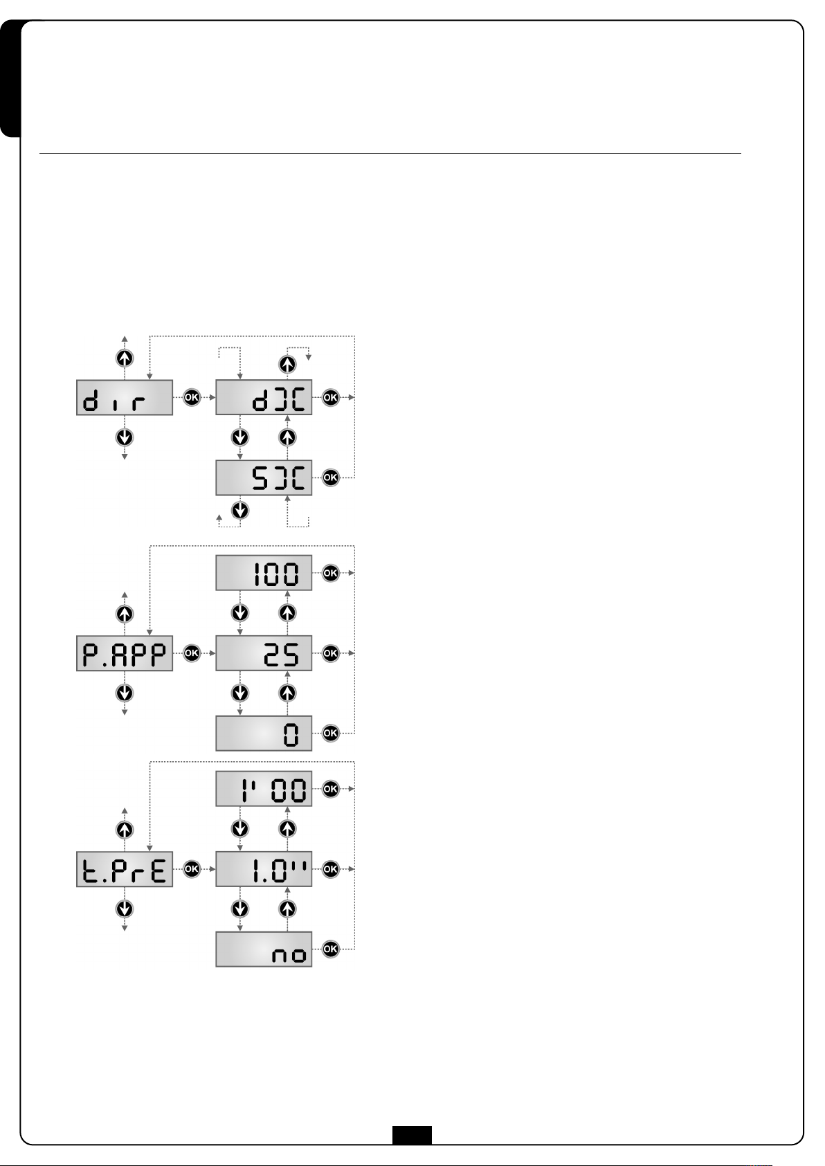
Direzione del cancello
Questo menù permette di invertire la direzione di apertura del
cancello senza scambiare i fili del motore e dei finecorsa.
dx il cancello apre verso destra
Sx il cancello apre verso sinistra
m ATTENZIONE: Per direzione del cancello si intende quella che si
vede guardando dal lato interno.
Apertura parziale
Percentuale della corsa che il cancello esegue in caso di apertura
comandata con Start Pedonale
Tempo prelampeggio
Prima di ogni movimento del cancello, il lampeggiatore viene attivato
per il tempo t.PrE, per segnalare l’imminente manovra
22
Page 25
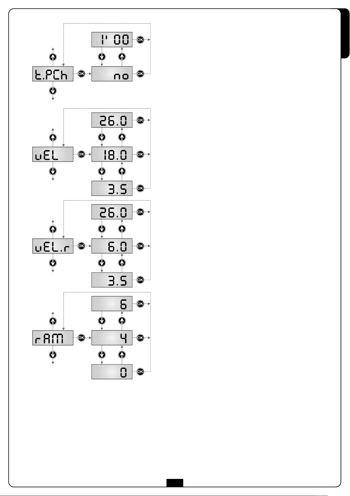
Tempo prelampeggio differente per la chiusura
Se si assegna un valore a questo parametro, la centrale attiverà il
prelampeggio prima della fase di chiusura per il tempo impostato in
questo menù (mantenendo il tempo impostato nel menù t.PrE per
l’apertura).
Se si seleziona no il tempo di prelampeggio impostato nel menù t.PrE
viene utilizzato in apertura e chiusura.
Se si desidera impostare il prelampeggio solo in chiusura è sufficiente
impostare un valore per t.P.C.h. e selezionare no per il menù t.PrE
NOTA: non è possibile impostare il prelampeggio solo in apertura.
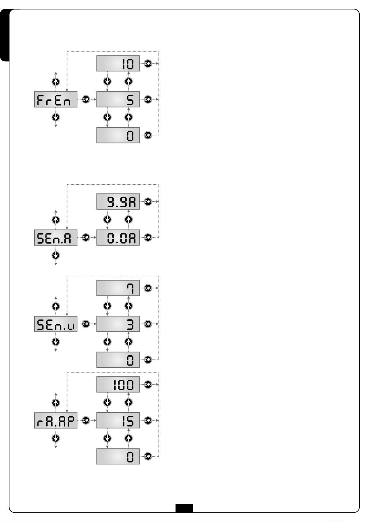
Velocità durante il funzionamento normale
Questo menù permette regolare la velocità del cancello durante il
funzionamento normale.
Il valore visualizzato è in cm/s
ITALIANO
Velocità durante il rallentamento
Questo menù permette regolare la velocità del cancello durante la fase
di rallentamento.
Il valore visualizzato è in cm/s
NOTA: il valore massimo impostabile è pari al valore impostato nel
menù vEL
Rampa di avviamento
Per non sollecitare eccessivamente il motore, a inizio movimento la
potenza viene incrementata gradualmente, fino a raggiungere il valore
impostato. Maggiore è il valore impostato, più lunga è la durata della
rampa, cioè più tempo è necessario per raggiungere il valore di potenza
nominale.
23
Page 26
ITALIANO
Funzione freno
Quando si utilizza un motore scorrevole su di un cancello molto pesante,
a causa dell'inerzia, il cancello non si blocca immediatamente quando
viene arrestato e il suo movimento può protrarsi anche per una decina di
centimetri, pregiudicando il funzionamento delle sicurezze.
Questo menù permette di attivare la funzione freno grazie alla quale è
possibile bloccare immediatamente il cancello, in seguito ad un
comando o all'intervento di una sicurezza.
0 la funzione freno non è mai attiva
1 ÷ 10 la funzione freno è attiva. La potenza di frenata è proporzionale
al valore impostato.
A seguito di un intervento della costa sensibile o del sensore di ostacoli,
o di un comando di STOP, la frenata viene sempre effettuata con la
massima potenza, indipendentemente dal valore impostato (purchè
maggiore di 0), per garantire una rapida inversione.
ATTENZIONE: Ogni frenata comporta uno stress meccanico dei
componenti del motore. Si consiglia di impostare il minimo valore per il
quale si ha uno spazio d’arresto soddisfacente.
Abilitazione del sensore di ostacoli
AMPEROMETRICO
Questo menù permette la regolazione della sensibilità del sensore di
ostacoli AMPEROMETRICO.
Quando la corrente assorbita dal motore supera il valore impostato, la
centrale rileva un allarme.
Se si imposta 0.0A la funzione viene disabilitata.
Per il funzionamento del sensore fare riferimento al capitolo 10
Abilitazione del sensore di ostacoli DI VELOCITÀ
Questo menù permette la regolazione della sensibilità del sensore di
ostacoli DI VELOCITÀ.
Quando la velocità del motore scende sotto il valore impostato, la
centrale rileva un allarme.
Il valore visualizzato è in cm/s
Per il funzionamento del sensore fare riferimento al capitolo 10
Rallentamento in apertura
Questo menù permette di regolare la percentuale della corsa che viene
eseguita a velocità ridotta durante l’ultimo tratto di apertura.
24
Page 27
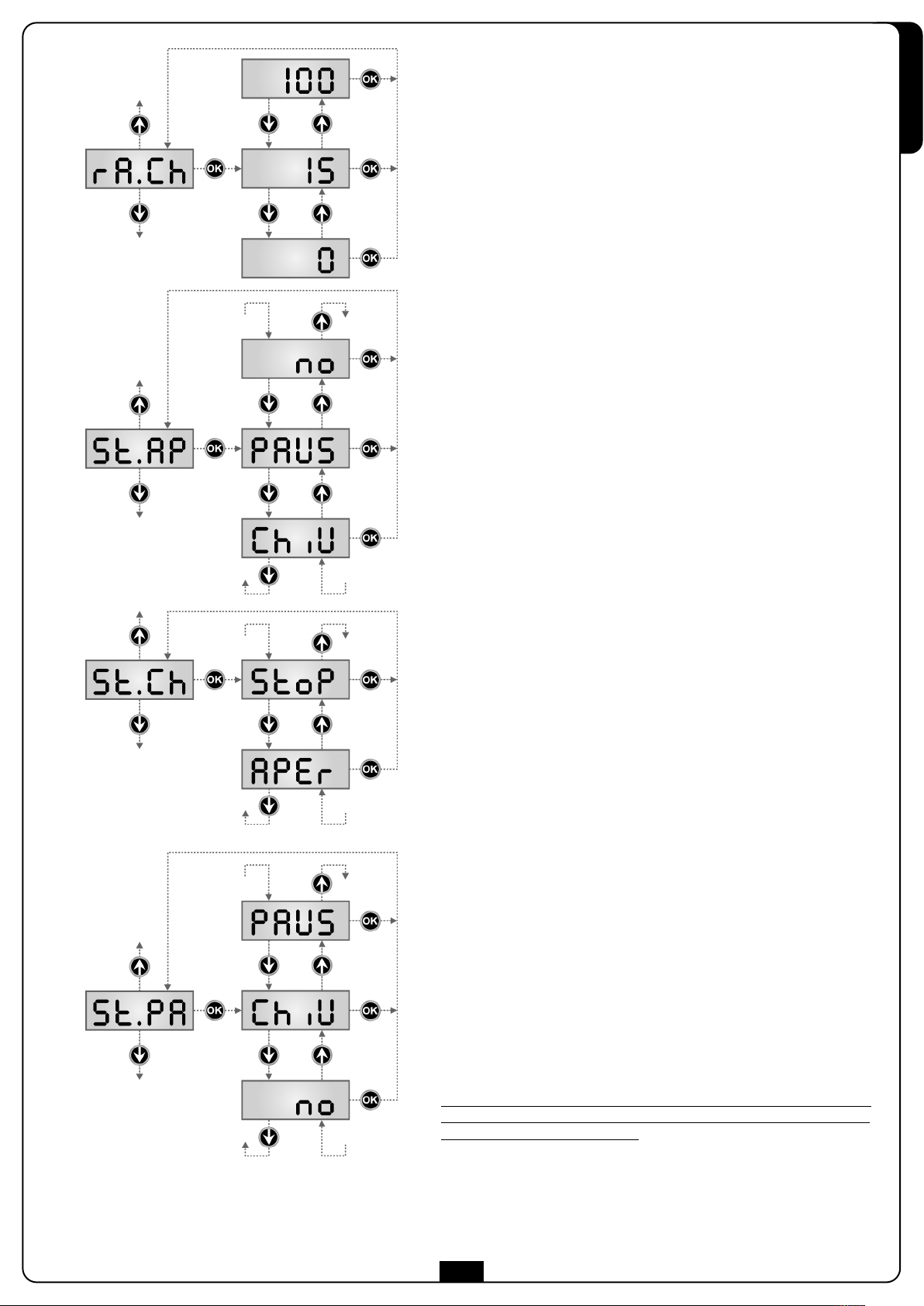
Rallentamento in chiusura
Questo menù permette di regolare la percentuale della corsa che viene
eseguita a velocità ridotta durante l’ultimo tratto di chiusura.
Start in apertura
Questo menù permette di stabilire il comportamento della centrale se
viene ricevuto un comando di Start durante la fase di apertura.
PAUS Il cancello si ferma ed entra in pausa
ChiU Il cancello inizia immediatamente a richiudersi
no Il cancello continua ad aprirsi (il comando viene ignorato)
Per impostare la logica di funzionamento “passo passo”, scegliere
l’opzione PAUS.
Per impostare la logica di funzionamento “apre sempre”, scegliere
l’opzione no.
ITALIANO
Start in chiusura
Questo menù permette di stabilire il comportamento della centrale se
viene ricevuto un comando di Start durante la fase di chiusura.
StoP Il cancello si ferma e il ciclo viene considerato concluso
APEr Il cancello si riapre
Per impostare la logica di funzionamento “passo passo”, scegliere
l’opzione StoP.
Per impostare la logica di funzionamento “apre sempre”, scegliere
l’opzione APEr.
Start in pausa
Questo menù permette di stabilire il comportamento della centrale se
viene ricevuto un comando di Start mentre il cancello è aperto in pausa.
ChiU Il cancello inizia a richiudersi
no Il comando viene ignorato
PAUS viene ricaricato il tempo di pausa
Per impostare la logica di funzionamento “passo passo”, scegliere
l’opzione ChiU.
Per impostare la logica di funzionamento “apre sempre”, scegliere
l’opzione no o PAUS.
Indipendentemente dall’opzione scelta, il comando di Start fa richiudere
cancello se questo è stato bloccato con un comando di Stop o se non è
abilitata la richiusura automatica.
25
il
Page 28
ITALIANO
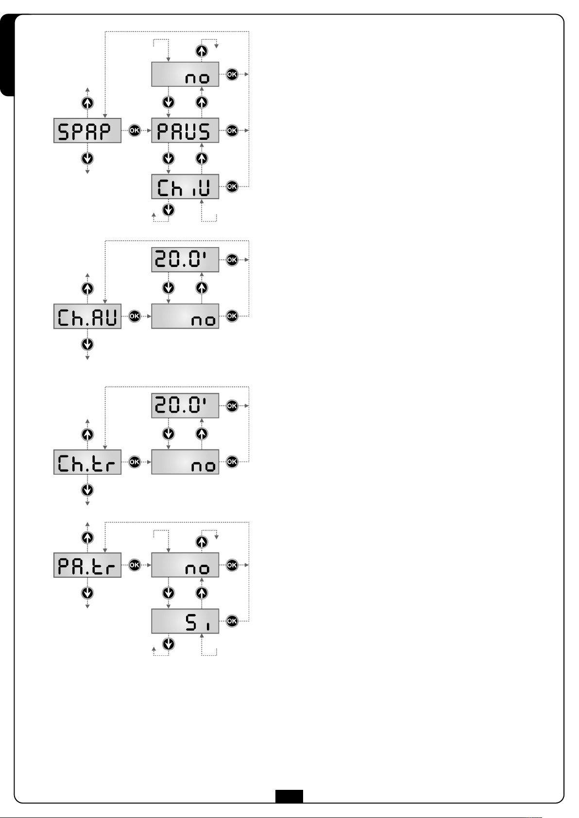
tart pedonale in apertura parziale
S
Questo menù permette di stabilire il comportamento della centrale se
viene ricevuto un comando di Start Pedonale durante la fase di
pertura parziale.
a
PAUS Il cancello si ferma ed entra in pausa
ChiU Il cancello inizia immediatamente a richiudersi
no Il cancello continua ad aprirsi (il comando viene ignorato)
m A
d
Pedonale viene sempre ignorato durante un’apertura totale.
TTENZIONE: Un comando di Start ricevuto in qualunque fase
ell’apertura parziale provoca un’apertura totale; il comando di Start
Chiusura automatica
Nel funzionamento automatico, la centrale richiude automaticamente il
cancello allo scadere di un tempo prefissato.
Se abilitato dal menu St.PA, il comando di Start permette di chiudere il
cancello anche prima dello scadere del tempo impostato.
Nel funzionamento semiautomatico, cioè se la funzione di chiusura
automatica viene disabilitata portando il valore a zero (il display
visualizza no), il cancello può essere richiuso solo con il comando di
Start: in questo caso l’impostazione del menu St.PA viene ignorata.
Se durante la pausa viene ricevuto un comando di stop, la centrale
passa automaticamente al funzionamento semiautomatico.
Chiusura dopo il transito
Nel funzionamento automatico, ogni volta che interviene una
fotocellula durante la pausa, il conteggio del tempo di pausa
ricomincia dal valore impostato in questo menù.
Analogamente, se la fotocellula interviene durante l’apertura, viene
immediatamente caricato questo tempo come tempo di pausa.
Questa funzione permette di avere una rapida chiusura dopo il transito
attraverso il cancello, per cui solitamente si utilizza un tempo inferiore a
CH.AU.
Se si imposta no viene utilizzato il tempo Ch.AU.
Nel funzionamento semiautomatico questa funzione non è attiva.
Pausa dopo il transito
Per rendere minimo il tempo in cui il cancello rimane aperto, è possibile
fare in modo che il cancello si fermi non appena viene rilevato il
passaggio davanti alle fotocellule. Se abilitato il funzionamento
automatico, come tempo di pausa viene caricato il valore Ch.tr.
Se sono installate fotocellule sia di tipo 1 sia di tipo 2, il cancello va in
pausa solo dopo che è stato rilevato il passaggio davanti ad entrambe.
26
Page 29
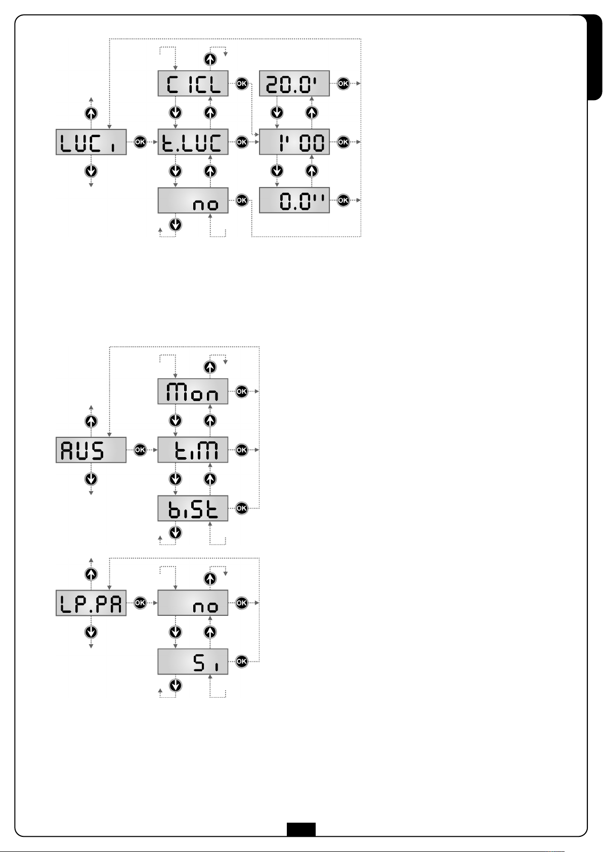
Luci di cortesia
Questo menù permette di impostare il
funzionamento delle luci di cortesia in modo
automatico durante il ciclo di apertura del
ancello.
c
.LUC il relè viene attivato al ricevimento del comando di start o start pedonale; scegliendo questa opzione si entra in un sottomenù che
t
permette di impostare la durata dell’attivazione del relè da 0.0” a 20’0 (default 1’00).
Allo scadere del timer il relè viene disattivato.
no il relè delle luci di cortesia non viene attivato automaticamente.
CiCL il relè viene attivato durante le fasi di movimento del cancello; quando il cancello si ferma (aperto o chiuso) il relè viene
mantenuto ancora attivo per il tempo impostato nel sottomenù
Se si attiva l’opzione LP.PA il relè viene tenuto attivo anche durante la pausa.
t.LUC
.
ITALIANO
Canale Ausiliario
Questo menù permette di impostare il funzionamento del relè di
accensione delle luci di cortesia mediante un telecomando memorizzato
sul canale 4 del ricevitore.
tiM il relè viene attivato al ricevimento della trasmissione del
telecomando; viene disattivato dopo il tempo impostato per il
parametro t.LUC nel menù LUCi
biSt lo stato del relè commuta ad ogni trasmissione del
telecomando ricevuta.
Mon il relè viene attivato e per tutta la durata della
trasmissione del telecomando. Rilasciando il pulsante del
telecomando il relè viene disattivato.
Lampeggiatore in pausa
Normalmente il lampeggiatore funziona solo durante il movimento del
cancello.
Se questa funzione è abilitata, il lampeggiatore funziona anche durante
il tempo di pausa (cancello aperto con chiusura automatica attiva).
27
Page 30
ITALIANO
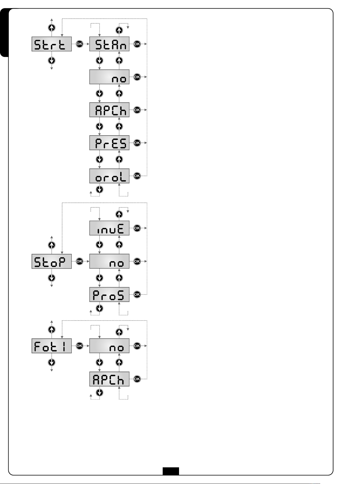
Funzione degli ingressi di Start
Questo menù permette di scegliere la modalità di funzionamento degli
ingressi (vedere paragrafo Ingressi di Attivazione):
StAn Funzionamento standard degli ingressi di Start e Start Pedonale,
secondo le impostazioni dei menu.
no Gli ingressi di Start da morsettiera sono disabilitati.
Gli ingressi radio funzionano secondo la modalità StAn.
P.CH L’impulso di Start comanda sempre l’apertura, l’impulso di Start
A
Pedonale comanda sempre la chiusura.
PrES Funzionamento uomo presente; il cancello si apre fintanto che
l’ingresso Start è chiuso e si chiude fintanto che l’ingresso Start
Pedonale è chiuso.
oroL Funzionamento con un timer; il cancello rimane aperto fintanto
che l’ingresso Start o Start Pedonale rimane chiuso; all'aprirsi
del contatto inizia il conteggio del tempo di pausa.
Ingresso Stop
Questo menù permette di selezionare le funzioni associate al comando
di STOP.
no L’ ingresso STOP è disabilitato.
Non è necessario ponticellare con il comune.
ProS Il comando di STOP ferma il cancello: al successivo comando di
START il cancello riprende il moto nella direzione precedente.
InvE Il comando di STOP ferma il cancello: al successivo comando di
START il cancello riprende il moto nella direzione opposta alla
precedente
NOTA: durante la pausa il comando di STOP ferma il conteggio del
tempo di pausa, il successivo comando di START richiuderà sempre il
cancello.
Ingresso foto 1
Questo menù permette di abilitare l’ingresso per le fotocellule di tipo 1,
cioè attive in apertura e in chiusura (vedere il paragrafo installazione).
no Ingresso disabilitato (la centrale lo ignora).
Non è necessario ponticellare con il comune.
AP.CH Ingresso abilitato.
28
Page 31

Ingresso foto 2
Questo menù permette di abilitare l’ingresso per le fotocellule di tipo 2,
ioè non attive in apertura (vedere il paragrafo installazione).
c
no Ingresso disabilitato (la centrale lo ignora).
Non è necessario ponticellare con il comune.
F.CH Ingresso abilitato anche a cancello fermo: la manovra di
C
apertura non inizia se la fotocellula è interrotta.
CH Ingresso abilitato solo in chiusura
ATTENZIONE: se si sceglie questa opzione è necessario
isabilitare il test delle fotocellule
d
.
Test delle fotocellule
Per garantire una maggior sicurezza per l’utente, la centrale opera,
prima che inizi ogni ciclo di operazione normale, un test di
funzionamento sulle fotocellule. Se non ci sono anomalie funzionali il
cancello entra in movimento. In caso contrario resta fermo e il
lampeggiante si accende per 5 secondi. Tutto il ciclo di test dura meno
di un secondo.
ITALIANO
m ATTENZIONE: V2 consiglia di mantenere attivo il Test delle
fotocellule al fine di garantire una maggior sicurezza del sistema.
Ingresso Costa Sensibile 1
Questo menù permette di abilitare l’ingresso per le coste sensibili di tipo
1, cioè fisse (vedere il paragrafo installazione).
no Ingresso disabilitato (la centrale lo ignora).
Non è necessario ponticellare con il comune.
AP Ingresso abilitato durante l’apertura e disabilitato durante la
chiusura
APCH Ingresso abilitato in apertura e chiusura
Ingresso Costa Sensibile 2
Questo menù permette di abilitare l’ingresso per le coste sensibili di tipo
2, cioè mobili (vedere il paragrafo installazione).
no Ingresso disabilitato (la centrale lo ignora).
Non è necessario ponticellare con il comune.
Ch Ingresso abilitato durante la chiusura e disabilitato durante
l’apertura
APCH Ingresso abilitato in apertura e chiusura
29
Page 32

ITALIANO
Test delle coste di sicurezza
Questo menù permette di impostare il metodo di verfica del
funzionamento delle coste di sicurezza.
no Test disabilitato
rESi Test abilitato per coste a gomma resistiva
Foto Test abilitato per coste ottiche.
m ATTENZIONE: V2 consiglia di mantenere attivo il Test delle
coste di sicurezza al fine di garantire una maggior sicurezza del
sistema.
Ingresso Finecorsa
La centrale PD20 permette il collegamento di finecorsa magnetici a
effetto di HALL che vengono attivati dal movimento del cancello e
indicano alla centrale che il cancello ha raggiunto la posizione di
completa apertura o chiusura.
Si gli ingressi finecorsa sono abilitati.
no gli ingressi finecorsa non sono abilitati.
Abilitazione dispositivo ADI
Tramite questo menù è possibile abilitare il funzionamento del
dispositivo innestato sul connettore ADI.
no interfaccia disabilitata, eventuali segnalazioni non sono tenute
in considerazione
Si interfaccia abilitata
NOTA: selezionando la voce Si e premendo MENU si entra nel menù di
configurazione del dispositivo innestato nel connettore ADI.
Questo menù è gestito dal dispositivo stesso ed è diverso per ogni per
ogni dispositivo. Fare riferimento al manuale del dispositivo.
Se si seleziona la voce Si, ma nessun dispositivo è innestato , il display
visualizza una serie di trattini.
Quando si esce dal menù di configurazione del dispositivo ADI, si torna
alla voce i.ADi
Fine Programmazione
Questo menù permette di terminare la programmazione (sia
predefinita che personalizzata) salvando in memoria i dati
modificati.
no ulteriori modifiche da effettuare, non uscire dalla
programmazione.
Si modifiche terminate: fine programmazione, il display
visualizza il pannello di controllo.
I DATI IMPOSTATI SONO STATI SALVATI IN MEMORIA: LA
CENTRALE È ORA PRONTA PER L'UTILIZZO.
30
Page 33

13.1 - ANOMALIE DI FUNZIONAMENTO
In questo paragrafo vengono elencate alcune anomalie di
funzionamento che si possono presentare, ne viene indicata la
causa e la procedura per porvi rimedio.
Il led MAINS non si accende
Significa che manca tensione sulla scheda della centrale PD20.
1. Assicurarsi che non vi sia un’interruzione di tensione a
monte della centrale.
2. Prima di agire sulla centrale, togliere corrente tramite il
sezionatore installato sulla linea di alimentazione e
rimuovere il morsetto di alimentazione.
3. Controllare se il fusibile F1 è bruciato. In questo caso,
sostituirlo con uno di pari valore.
Il led OVERLOAD è acceso
Significa che è presente un sovraccarico sull’alimentazione degli
ccessori.
a
1 Rimuovere la parte estraibile contenente i morsetti da M1 a
M12. Il led OVERLOAD si spegne.
2 Eliminare la causa del sovraccarico.
3 Reinnestare la parte estraibile della morsettiera e verificare
che il led non si accenda nuovamente.
Errore 1
All’uscita dalla programmazione sul display appare la scritta
Err1
Significa che non è stato possibile salvare i dati modificati.
Questo malfunzionamento non è rimediabile dall’installatore.
La centrale deve essere inviata alla V2 S.p.A. per la riparazione.
Errore 2
Quando viene dato un comando di start il cancello non si apre e
sul display appare la scritta
Significa che la scheda inverter segnala un’anomalia.
NOTA: Se il motore è stato utilizzato in modo intensivo,
potrebbe essersi surriscaldato il driver dei motori.
Aspettare che si raffreddi e riprovare.
Errore 3
Quando viene dato un comando di start il cancello non si apre e
sul display appare la scritta
Significa che è fallito il test delle fotocellule.
1. Assicurarsi che nessun ostacolo abbia interrotto il fascio
delle fotocellule nel momento in cui è stato dato il comando
di start.
2. Assicurarsi che le fotocellule che sono state abilitate da menu
siano effettivamente installate.
3. Se vengono usate fotocellule di tipo 2, assicurarsi che la
voce di menu Fot2 sia impostata su CF.CH.
4. Assicurarsi che le fotocellule siano alimentate e funzionanti:
interrompendo il fascio si deve sentire lo scatto del relè.
Errore 4
Quando viene dato un comando di start il cancello non si apre (o
si apre solo parzialmente) e sul display appare la scritta
Significa che c’è un problema sul finecorsa.
Verificare il verso dei magneti, se sono al contrario è necessario
smontarli e invertirli.
Se i magneti sono installati correttamente significa che il sensore
finecorsa è danneggiato o il cablaggio che collega il sensore alla
centrale di comando è stato interrotto.Sostituire il sensore
finecorsa o parte del cablaggio danneggiato.
Se l’errore persiste inviare la centrale di comando alla V2 S.p.A.
per la riparazione.
Err2
Err3
Err4
Errore 5
Quando viene dato un comando di start il cancello non si apre e
sul display appare la scritta
ignifica che è fallito il test delle coste sensibili.
S
ssicurarsi che il menù relativo al test delle coste (Co.tE) siano
A
stati configurati in modo corretto.
Assicurarsi che le coste abilitate da menù siano effettivamente
installate.
Errore 6
Durante la manovra il motore si ferma e sul display compare la
scritta
Err6
ignifica che ci sono problemi di comunicazione con la scheda
S
inverter. Se il problema persiste la centrale deve essere inviata alla
V2 S.p.A. per la riparazione.
Errore 7
Quando viene dato un comando di start il cancello non si apre e
sul display compare la scritta
Indica un’anomalia nel funzionamento dell’encoder.
Encoder guasto o collegamento interrotto.
Errore 8
Quando si cerca di eseguire una funzione di autoapprendimento
si verifica una delle seguenti condizioni
1. Il comando viene rifiutato e sul display compare la scritta
Err5
Err7
Err8
Significa che l’impostazione della centrale non è compatibile
con la funzione richiesta.
Per poter eseguire l’autoapprendimento è necessario che gli
ingressi di Start siano abilitati in modalità standard (menù Strt
impostato su StAn) e l’interfaccia ADI sia disabilitata (menù
i.Adi impostato su no).
2. La procedura viene interrotta e sul display compare la scritta
Err8
Significa che è intervenuto un dispositivo di sicurezza.
Errore 9
Quando si cerca di modificare le impostazioni della centrale sul
display compare la scritta
Significa che la programmazione è stata bloccata con la chiave
di blocco programmazione CL1+ (codice 161213).
Per procedere con la modifica delle impostazioni è necessario
inserire nel connettore interfaccia ADI la stessa chiave usata
per attivare il blocco programmazione.
Errore 12
Quando viene dato un comando di start il cancello non si apre (o
si apre solo parzialmente) e sul display appare la scritta
Significa che è intervenuta la protezione termica del motore.
Il sistema tornerà a funzionare normalmente appena il motore si
sarà raffreddato.
Prelampeggio prolungato
Quando viene dato un comando di start il lampeggiatore si
accende immediatamente, ma il cancello tarda ad aprirsi.
Significa che è scaduto il conteggio di cicli impostato e la
centrale richiede un intervento di manutenzione.
Err9
Er I 2
ITALIANO
31
Page 34

13.2 - TABELLA FUNZIONI PD20
ITALIANO
DISPLAY DATI DESCRIZIONI DEFAULT
dir dX / Sx Direzione di apertura del cancello (visto dal lato interno) dx
P.APP 0 ÷ 100 Apertura parziale 25
t.PrE 0.5" ÷ 1.0' Tempo prelampeggio 1.0"
no - Prelampeggio disabilitato (corrisponde al valore 0)
t.PCh 0.5" ÷ 1.0' Tempo prelampeggio differente per la chiusura no
o
n
vEL 3.5 ÷ 26.0 Velocità durante il funzionamento normale 18
vEL.r 3.5 ÷ 26.0 Velocità durante il rallentamento 6
rAM 0 ÷ 6 Rampa di avviamento 4
FrEn 0 ÷ 10 Funzione freno 5
SEn.A 0.0A ÷ 9.9A Abilitazione del sensore di ostacoli amperometrico 0.0A
SEn.v 0 ÷ 7 Abilitazione del sensore di ostacoli di velocità 3
rA.AP 0 ÷ 100 Rallentamento in apertura 15
rA.Ch 0 ÷ 100 Rallentamento in chiusura 15
St.AP Start in apertura PAUS
PAUS - Il cancello va in pausa
Prelampeggio in chiusura uguale a t.PrE
-
MEMO
DATI
ChiU - Il cancello richiude
no - Il comando START non è sentito
St.Ch Start in chiusura StoP
Stop - Il cancello conclude il ciclo
APEr - Il cancello riapre
St.PA Start in pausa ChiU
ChiU - Il cancello richiude
no - Il comando di START non è sentito
PAUS - Viene ricaricato il tempo di pausa
SPAP Start pedonale in apertura PAUS
PAUS - Il cancello va in pausa
ChiU - Il cancello richiude
no - Il comando di START P. non è sentito
Ch.AU Richiusura automatica no
no - La richiusura automatica non è attiva (corrisponde al valore 0)
0.5"÷ 20.0' - Il cancello richiude dopo il tempo impostato
Ch.tr Chiusura dopo il transito no
no - Chiusura dopo il transito disabilitata (carica Ch.AU)
0.5"÷ 20.0' - Il cancello richiude dopo il tempo impostato
PA.tr no/Si Pausa dopo il transito no
LUCi Luci di cortesia
t.LUC - Funzionamento temporizzato (da 0 a 20’) 1’00
no - Funzione disattivata
CiCL - Accese per tutta la durata del ciclo
32
Page 35

ITALIANO
DISPLAY DATI DESCRIZIONI DEFAULT
US
A
tiM - Funzionamento temporizzato
biSt - Funzionamento bistabile
Mon - Funzionamento monostabile
LP.PA no/Si Lampeggiatore in pausa no
St.rt Ingressi di start StAn
StAn - Funzionamento standard
o
n
AP.CH - Comandi di apertura e chiusura separati
PrES - Funzionamento uomo presente
oroL - Funzionamento timer
StoP Ingresso di STOP no
no - L’ingresso è disabilitato: il comando di STOP non è sentito
ProS - Il comando di STOP ferma il cancello: lo START successivo non inverte il moto
invE - Il comando di STOP ferma il cancello: lo START successivo inverte il moto
Fot 1 Ingresso FOTO 1. no
anale ausiliario
C
Ingressi da morsettiera disabilitati
-
M
on
MEMO
ATI
D
no - Disabilitato.
APCh - Funziona come fotocellula attiva in apertura e in chiusura.
Fot 2 Ingresso FOTO 2. CFCh
CFCh - Funziona come fotocellula attiva in chiusura e con cancello fermo.
Ch - Funziona come fotocellula attiva solo in chiusura.
no - Disabilitato.
Ft.tE no/Si Test di funzionamento delle fotocellule no
CoS1 Ingresso costa 1 no
no - Ingresso non attivo
APCH - Ingresso attivo in apertura e chiusura
AP - Ingresso attivo solo in apertura
CoS2 Ingresso costa 2 no
no - Ingresso non attivo
APCH - Ingresso attivo in apertura e chiusura
CH - Ingresso attivo solo in chiusura
Co.tE Test di funzionamento delle coste di sicurezza no
no - Test disabilitato
rESi - Test abilitato per coste a gomma resistiva
Foto - Test abilitato per coste ottiche.
FC.En Si/no Ingressi finecorsa Si
i.ADi no/Si Abilitazione dispositivo ADI no
FinE Fine programmazione. no
no - Non esce dal menu di programmazione
Si - Esce dal menu di programmazione memorizzando i parametri impostati
33
Page 36

14 - COLLAUDO E MESSA IN SERVIZIO
15 - MANUTENZIONE
Queste sono le fasi più importanti nella realizzazione dell’automazione al
ine di garantire la massima sicurezza.
f
ITALIANO
V2 raccomanda l’utilizzo delle seguenti norme tecniche:
• EN 12445 (Sicurezza nell'uso di chiusure automatizzate,
etodi di prova)
m
• EN 12453 (Sicurezza nell'uso di chiusure automatizzate,
requisiti)
• EN 60204–1 (Sicurezza del macchinario, equipaggiamento
lettrico delle macchine, parte 1: regole generali)
e
In particolare, facendo riferimento alla tabella del paragrafo “VERIFICHE
PRELIMINARI e IDENTIFICAZIONE DELLA TIPOLOGIA DI UTILIZZO” nella
aggior parte dei casi sarà necessaria la misura della forza d’impatto
m
secondo quanto previsto dalla norma
EN 12445.
La regolazione della forza operativa è possibile tramite la
programmazione della scheda elettronica e Il profilo delle forze di impatto
deve essere misurato con un apposito strumento (anche lui certificato e
sottoposto a taratura annuale) in grado di tracciare il grafico forza-tempo.
Il risultato deve rispettare i seguenti valori massimi:
Forza
La manutenzione deve essere effettuata nel pieno rispetto
elle prescrizioni sulla sicurezza del presente manuale e
d
secondo quanto previsto dalle leggi e normative vigenti.
L’intervallo raccomandato tra ogni manutenzione è di sei
mesi, le verifiche previste dovrebbero riguardare almeno:
la perfetta efficienza di tutti i dispositivi di segnalazione
•
• la perfetta efficienza di tutti i dispositivi di sicurezza
• la misurazione delle forze operative del cancello
• la lubrificazione delle pari meccaniche dell’automazione
dove necessario)
(
• lo stato di usura delle parti meccaniche
dell’automazione
• lo stato di usura dei cavi elettrici degli attuatori
lettromeccanici
e
L’esito di ogni verifica và annotato in un registro di
manutenzione del cancello.
16 - SMALTIMENTO
Come per le operazioni d’installazione, anche al termine
della vita di questo prodotto, le operazioni di
smantellamento devono
essere eseguite da personale qualificato.
Forza dinamica
IMPATTO
Forza statica
SCHIACCIAMENTO
Tempo
Per una guida esaustiva all’installazione di automazioni e alla
documentazione da redigere, consigliamo di utilizzare le guide rilasciate
dall’associazione italiana UNAC e reperibili all’indirizzo web
www.v2home.com
Questo prodotto è costituito da vari tipi di materiali: alcuni
possono essere riciclati, altri devono essere smaltiti.
Informatevi sui sistemi di riciclaggio o smaltimento previsti
dai regolamenti vigenti nel vostro territorio, per questa
categoria di prodotto.
Attenzione! – Alcune parti del prodotto possono
contenere sostanze inquinanti o pericolose che, se disperse
nell’ambiente, potrebbero provocare effetti dannosi
sull’ambiente stesso e sulla salute umana.
Come indicato dal simbolo a lato, è vietato gettare questo
prodotto nei rifiuti domestici. Eseguire quindi la “raccolta
separata” per lo smaltimento, secondo i metodi previsti dai
regolamenti vigenti sul vostro territorio, oppure
riconsegnare il prodotto al venditore nel momento
dell’acquisto di un nuovo prodotto equivalente.
Attenzione! – i regolamenti vigenti a livello locale
possono prevedere pesanti sanzioni in caso di smaltimento
abusivo di questo prodotto.
34
Page 37

MANUALE PER L’UTILIZZATORE DELL’AUTOMAZIONE
AVVERTENZE PER L’UTILIZZATORE DELL’AUTOMAZIONE
Un impianto di automazione è una bella comodità, oltre che un valido sistema di sicurezza e, con poche, semplici attenzioni, è destinato
a durare negli anni.
Anche se l’automazione in vostro possesso soddisfa il livello di sicurezza richiesto dalle normative, questo non esclude l’esistenza di un
“rischio residuo”, cioè la possibilità che si possano generare situazioni di pericolo, solitamente dovute ad un utilizzo incosciente o
addirittura errato, per questo motivo desideriamo darvi alcuni consigli sui comportamenti da seguire per evitare ogni inconveniente:
rima di usare per la prima volta l’automazione, fatevi spiegare dall’installatore l’origine dei rischi residui, e dedicate qualche
P
minuto alla lettura del manuale di istruzioni ed avvertenze per l’utilizzatore consegnatovi dall’installatore.
Conservate il manuale per ogni dubbio futuro e consegnatelo ad un eventuale nuovo proprietario dell’automazione.
a vostra automazione è un macchinario che esegue fedelmente i vostri comandi; un uso incosciente ed improprio può farlo
L
diventare pericoloso: non comandate il movimento dell’automazione se nel suo raggio di azione si trovano persone, animali o cose.
Bambini: un impianto di automazione, installato secondo le norme tecniche, garantisce un alto grado di sicurezza.
comunque prudente vietare ai bambini di giocare in prossimità dell’automazione e per evitare attivazioni involontarie; non lasciare mai
È
i telecomandi alla loro portata: non è un gioco!
Anomalie: non appena notate qualunque comportamento anomalo da parte dell’automazione, togliete alimentazione elettrica
all’impianto ed eseguite lo sblocco manuale. Non tentate da soli alcuna riparazione, ma richiedete l’intervento del vostro installatore di
fiducia: nel frattempo l’impianto può funzionare come un’apertura non automatizzata.
ITALIANO
Manutenzione: come ogni macchinario la vostra automazione ha bisogno di una manutenzione periodica affinché possa funzionare
più a lungo possibile ed in completa sicurezza. Concordate con il vostro installatore un piano di manutenzione con frequenza periodica;
V2spa raccomanda un piano di manutenzione da eseguire ogni 6 mesi per un normale utilizzo domestico, ma questo periodo può
variare in funzione dell’intensità d’uso.
Qualunque intervento di controllo, manutenzione o riparazione deve essere eseguito solo da personale qualificato. Anche se ritenete di
saperlo fare, non modificate l’impianto ed i parametri di programmazione e di regolazione dell’automazione: la responsabilità è del
vostro installatore.
Il collaudo finale, le manutenzioni periodiche e le eventuali riparazioni devono essere documentate da chi le esegue e i documenti
conservati dal proprietario dell’impianto.
Smaltimento: al termine della vita dell’automazione, assicuratevi che lo smantellamento sia eseguito da personale qualificato e che i
materiali vengano riciclati o smaltiti secondo le norme valide a livello locale.
Importante: se il vostro impianto è dotato di un radiocomando che dopo qualche tempo vi sembra funzionare peggio, oppure non
funzionare affatto, potrebbe semplicemente dipendere dall’esaurimento della pila (a seconda del tipo, possono trascorrere da diversi
mesi fino a due/tre anni). Prima di rivolgervi all’installatore provate a scambiare la pila con quella di un altro trasmettitore eventualmente
funzionante: se questa fosse la causa dell’anomalia, sarà sufficiente sostituire la pila con altra dello stesso tipo.
Siete soddisfatti? Nel caso voleste aggiungere nella vostra casa un nuovo impianto di automazione, rivolgendovi allo stesso installatore
chiedete un prodotto V2spa: vi garantirete i prodotti più evoluti del mercato e la massima compatibilità delle automazioni già esistenti.
Grazie per aver letto queste raccomandazioni e vi invitiamo, per ogni esigenza presente o futura di rivolgetevi con fiducia al vostro
installatore.
SBLOCCO MOTORE
In caso di mancanza di corrente elettrica, il cancello può
essere sbloccato agendo sul motore:
1. Aprire il copriserratura J presente sul lato frontale del motore.
2. Inserire la chiave K nella serratura e girare in senso orario per
aprire l’accesso allo sblocco posto a lato.
3. Inserire la chiave L nel foro e ruotare in senso orario fino a
finecorsa.
Per ripristinare l’automazione procedere come segue:
1. Ruotare la chiave L in senso antiorario fino a finecorsa ed
estrarla;
2. Ruotare la chiave K in senso antiorario in modo da chiudere
l’accesso allo sblocco ed estrarla.
3. Coprire la serratura con lo sportello J.
35
Page 38

ITALIANO
36
Page 39

INDEX
1 - GENERAL SAFETY INFORMATION ....................................................................................................................................38
1.1 - PRELIMINARY CHECKS AND IDENTIFICATION OF THE TYPE TO BE USED ..................................................................39
1.2 - TECHNICAL ASSISTANCE SERVICE ..........................................................................................................................40
.3 - EC DECLARATION OF INCORPORATION FOR PARTLY COMPLETED MACHINERY ......................................................40
1
2 - TECHNICAL DATA..............................................................................................................................................................41
- INSTALLATION OF THE MOTOR ......................................................................................................................................42
3
3.1 - POSITIONING OF THE MOTOR ................................................................................................................................42
3.2 - MOUNTING THE RACK............................................................................................................................................44
3.3 - FIXING OF THE MOTOR ..........................................................................................................................................44
.4 - INSTALLING THE MAGNETIC LIMIT SWITCHES ........................................................................................................45
3
3.5 - MOTOR OVERRIDING SYSTEM ................................................................................................................................46
3.6 - INSTALLATION LAYOUT ..........................................................................................................................................46
4 - CONTROL UNIT ................................................................................................................................................................47
4.1 - POWER SUPPLY ......................................................................................................................................................47
4.2 - FLASHING LIGHT ....................................................................................................................................................47
4.3 - COURTESY LIGHTS..................................................................................................................................................47
4.4 - PHOTOCELLS ..........................................................................................................................................................48
4.5 - SAFETY RIBBONS ....................................................................................................................................................48
4.6 - STOP ......................................................................................................................................................................49
4.7 - ACTIVATION INPUTS................................................................................................................................................49
4.8 - EXTERNAL AERIAL ..................................................................................................................................................49
4.9 - PLUG IN RECEIVER ..................................................................................................................................................50
4.10 - ADI INTERFACE......................................................................................................................................................50
4.11 - ELECTRICAL CONNECTION....................................................................................................................................51
ENGLISH
5 - CONTROL PANEL ..............................................................................................................................................................52
5.1 - DISPLAY ..................................................................................................................................................................52
5.2 - USE OF THE KEYS FOR PROGRAMMING..................................................................................................................52
6 - ACCESSING THE CONTROL UNIT SETTINGS ....................................................................................................................53
7 - QUICK CONFIGURATION ..................................................................................................................................................54
8 - LOADING THE DEFAULT PARAMETERS............................................................................................................................54
9 - SELF-LEARNING OF WORKING TIMES..............................................................................................................................55
10 - OPERATION OF OBSTACLE SENSOR ..............................................................................................................................56
11 - INVERTER BOARD FUNCTIONAL TEST ..........................................................................................................................56
12 - READING OF CYCLE COUNTER ......................................................................................................................................57
13 - PROGRAMMING THE CONTROL UNIT ..........................................................................................................................58
13.1 - OPERATION DEFECTS ............................................................................................................................................67
13.2 - FUNCTION TABLE..................................................................................................................................................68
14 - TESTING AND START-UP ................................................................................................................................................70
15 - MAINTENANCE ..............................................................................................................................................................70
16 - DISPOSAL OF THE PRODUCT..........................................................................................................................................70
37
Page 40

AUTOMATION DEVICE INSTALLERS MANUAL
1 - GENERAL SAFETY INFORMATION
m Prior to proceeding with installation, it is essential the instructions be read in full, since they contain important
information regarding safety, installation, use and maintenance.
AUTOMATION MUST BE IMPLEMENTED IN COMPLIANCE WITH THE EUROPEAN REGULATIONS IN FORCE:
EN 60204-1, EN 12445, EN 12453, EN 13241-1, EN 12635
ENGLISH
• The installer must provide for a device (es. magnetotermical switch) ensuring the omnipolar sectioning of the equipment from the
power supply. The standards require a separation of the contacts of at least 3 mm in each pole (EN 60335-1).
• The plastic case has an IP44 insulation; to connect flexible or rigid pipes, use pipefittings having the same insulation level.
Installation requires mechanical and electrical skills, therefore it shall be carried out by qualified personnel only, who can issue the
•
Compliance Certificate concerning the whole installation (Machine Directive 2006/42/CEE, Annex IIA).
• Also the automation upstream electric system shall comply with the laws and rules in force and be carried out workmanlike.
• We recommend to make use of an emergency button, to be installed by the automation (connected to the control unit STOP input) so
hat the gate may be immediately stopped in case of danger.
t
• For correct installation of the system, we recommend following the instructions issued by UNAC very carefully, which can be consulted
at the following web site: www.v2home.com
• This instruction manual is only for qualified technicians, who specialize in installations and automations.
• The contents of this instruction manual do not concern the end user.
• Every programming and/or every maintenance service should be done only by qualified technicians.
• Anything not expressly described in these instructions is prohibited; unforeseen uses may be a source of danger to people and property.
• Do not install the product in explosive environments and atmospheres: the presence of inflammable gases or fumes is a serious safety
hazard.
• Do not make any modifications to any part of the automation device, or the accessories connected to it, unless described in this
manual.
• Any other modifications will void the warranty on the product.
• The installation steps should be conducted so as to avoid rainy weather, which can expose electronic circuits to dangerous water
seepage.
• All operations requiring the casing of the device to opened should be performed with the control unit disconnected from the electricity
supply and with a warning notice displayed, for example: ”CAUTION, MAINTENANCE IN PROGRESS”.
• Avoid exposing the device close to sources of heat and flame.
• In the event of interventions on automatic or differential breakers or fuses, it is essential that faults be identified and resolved prior to
resetting. In the case of faults that cannot be resolved using the information to be found in this manual, consult the V2 customer
assistance service.
• V2 declines all responsibility for failure to comply with good construction practice standards in addition to structural deformation of the
gate that might occur during use.
• V2 reserves the right to make modifications to the product without prior warning.
• Installation/maintenance personnel should wear individual protection devices (IPDs), such as overalls, safety helmets, boots and gloves.
• The ambient operating temperature should be that indicated in the technical characteristics table.
• The automation device should be shut down immediately in the event of any anomalous or hazardous situation; the fault or
malfunction should be immediately reported to the person responsible.
• All safety and hazard warnings on the machinery and equipment should be complied with.
• Electromechanical actuators for gates are not intended to be used by people (including children) with diminished physical, sensory or
mental capacity, or lacking in experience or knowledge, unless they are under supervision or have been instructed in use of the actuator
by a person responsible for safety.
V2 has the right to modify the product without previous notice; it also declines any responsibility to damage or injury to
people or things caused by improper use or wrong installation.
38
Page 41

.1 - PRELIMINARY CHECKS AND IDENTIFICATION OF THE TYPE TO BE USED
1
The automation device should not be used until installation, as specified in “Testing and start-up”, has been performed.
It should be remembered that the device does not compensate for defects caused by improper installation, or poor maintenance, thus,
rior to proceeding with installation, ensure that the structure is suitable and meets current standards and, if necessary, perform any
p
structural modifications aimed at the implementation of safety gaps and the protection or segregation of all crushing, shearing and transit
zones, and verify that:
• The gate has no friction points, either during closing or opening.
• The gate is well balanced, i.e. there is no tendency to move spontaneously when stopped in any position.
• The position identified for fixing the motor reducer allows easy and safe manual manoeuvring, compatible with the size of the motor
reducer itself.
• The support on which the automation device will be fixed is solid and durable.
• The mains power supply to which the automation device is connected has a dedicated safety earthing system and differential breaker
with tripping current less than or equal to 30 mA (the breaker gap distance should be greater than or equal to 3 mm).
Warning: The minimum safety level depends on the type of use; please refer to the following outline:
Closure use type
ENGLISH
Group 1
Type of activation commands
Man-present command A B Not possible
Remote control and closure in view
(e.g. infrared)
Remote control and closure not in view
(e.g. radio)
Automatic control
(e.g. timed closure control)
Group 1 - Only a limited number of people are authorised for use, and closure is not in a public area. Examples of this type are gates inside
business premises, where the sole users are employees, or a part of them who have been suitably informed.
Group 2 - Only a limited number of people are authorised for use, but in this case, closure is in a public area. An example of this may be a
company gate that accesses onto a public street, and which is only used by employees.
Group 3 - Anyone can use the automated closure, which is thus located on public land. For example the access gate to a supermarket or an
office, or a hospital.
Protection A - Closure is activated by means of a control button with the person present, i.e. with maintained action.
Protection B - With the person present, closure is activated by a command controlled by means of a key-switch or the like, in order to
prevent use by unauthorised persons.
Informed people
(use in private area)
C or E C or E C and D or E
C or E C and D or E C and D or E
C and D or E C and D or E C and D or E
Group 2
Informed people
(use in public area)
Group 3
Informed people
(unlimited use)
Protection C - Restricts the force of the leaf of the door or gate. I.e., in the case of the gate striking an obstacle, the impact force must fall
within a curve established by the regulations.
Protection D - Devices, such as photocells, capable of detecting the presence of people or obstacles. They may be active on just one side or
on both sides of the door or gate.
Protection E - Sensitive devices, such as footboards or immaterial barriers, capable of detecting the presence of a person, and installed in
such a way that the latter cannot be struck in any way by a moving leaf or panel. These devices should be active within the entire “danger
zone” of the gate. The Machinery Directive defines “Danger Zone” as any zone surrounding and/or near machinery where the presence of
an exposed person constitutes a risk to the health and safety of that person.
The risk analysis should take into consideration all danger zones for the automation device, which should be appropriately
protected and marked.
In a clearly visible area, apply a sign with information identifying the motorised door or gate.
The installer should provide the user with all the information relating to automatic operation, emergency opening and
maintenance of the motorised door or gate.
39
Page 42

.2 - TECHNICAL ASSISTANCE SERVICE
1
For any installation problem please contact our Customer Service at the number +39-0172.812411 operating Monday to Friday
from 8:30 to 12:30 and from 14:00 to 18:00.
1.3 - EC DECLARATION OF INCORPORATION FOR PARTLY COMPLETED MACHINERY
(DIRECTIVE 2006/42/EC, ANNEX II-B)
The manufacturer V2 S.p.A., headquarters in Corso Principi di Piemonte 65, 12035, Racconigi (CN), Italy
Under its sole responsibility hereby declares that:
ENGLISH
the partly completed machinery model(s):
FORTECO2500-I
Identification number and year of manufacturing: typed on nameplate
Description: electromechanical actuator for sliding gates
• is intended to be installed on sliding gates, to create a machine according to the provisions of the Directive 2006/42/EC.
The machinery must not be put into service until the final machinery into which it has to be incorporated has been declared in conformity
with the provisions of the Directive 2006/42/EC (annex II-A).
• is compliant with the applicable essential safety requirements of the following Directives:
Machinery Directive 2006/42/EC (annex I, chapter 1)
Low Voltage Directive 2006/95/EC
Electromagnetic Compatibility Directive 2004/108/EC
Radio Directive 99/05/EC
The relevant technical documentation is available at the national authorities’ request after justifiable request to:
V2 S.p.A., Corso Principi di Piemonte 65, 12035, Racconigi (CN), Italy
The person empowered to draw up the declaration and to provide the technical documentation:
Cosimo De Falco
Legal representative of V2 S.p.A.
Racconigi, 05/04/2012
40
Page 43

2 - TECHNICAL DATA
Gate maximum weight 2500 Kg
ower supply
P
Maximum power 650 W
Idling current 0,5 A
ull load current
F
Gate speed 0,06 ÷ 0,25 m/s
Maximum thrust 1660 N
Duty cycle 50
Pinion M4 - Z18
orking temperature
W
Motor weight 19 Kg
Protection degree IP44
Maximum load on 24 Vac accessories 10W
Protection fuses F1 = 8A
30VAC / 50Hz
2
,7 A
3
20°C ÷ +55°C
-
ENGLISH
41
Page 44

3 - INSTALLATION OF THE MOTOR
PREPARATORY STEPS
CAREFULLY OBSERVE EUROPEAN REGULATIONS EN12445 AND EN12453 (WHICH REPLACE UNI 8612).
Always check the following:
• Your gate should have a strong and suitable build; no wickets should be present on the sliding gate.
• The sliding gate should not tilt excessively during its entire run.
ENGLISH
• The gate should be able to slide freely on its guiding surface without an excessive friction.
• Install both closing and opening limit switches, in order to prevent the gate going off the guiding surface.
• Remove any manual locks.
• Bring power cable ducts near the bottom of the gate (diameter 20 / 30 mm) and of the external devices
(photocells, flasher, key selector).
3.1 - POSITIONING OF THE MOTOR
To fix FORTECO, follow the instructions below:
1. use the measurements indicated in the drawing for the foundations
2. Arrange for one or two pipes for the passage of electric cables
3. Assemble the 4 clamps on the anchoring plate and fix them with the 4 bolts issued with the motor
42
Page 45

4. Pour the concrete and position the anchoring plate
m WARNING: check that the plate be on a perfectly levelled surface and parallel to the gate
5. Wait for the complete setting of the concrete
6. Unscrew the bolts fixing the base to the clamps and put the motor on the plate
7. Insert the 4 grains with their nuts in the proper place. Adjust the 4 grains to make the motor be perfectly levelled
ENGLISH
8. Control that the motor is perfectly parallel to the gate, then insert the 4 washers R and lightly screw the 4 bolts D
m WARNING: put the washer G into the hole for the passing of the cables as shown in the picture. Pierce the washer to let the cable
to be connected to the control unit pass, paying attention to the dimensions in order to avoid the entrance of insects and other small
animals.
43
Page 46

3.2 - MOUNTING THE RACK
Release the motor and turn the gate completely open. Fix all the rack elements to the gate, making sure that they stand at the same
height than the motor pinion. The rack MUST BE positioned 1 or 2 mm over the pinion of the motor all the gate length.
m WARNING: If the gate is very heavy we suggest to use an M4 22x22 rack (code. 162324)
ENGLISH
3.3 - FIXING OF THE MOTOR
Check the following points:
1. the motor must be on a levelled surface and perfectly parallel to the gate
2. the distance between pinion and rack must be 1 or 2 mm. If needed, adjust the 4 grains
3. the rack must be trued up with the pinion of the motor
4. the minimum distance between the maximum overall of the gate and the case of the pinion of the motor must be of at least 5 mm
Check the above indicated conditions and proceed fixing the 4 bolts D anchoring the motor to the plate
.
44
Page 47

3.4 - INSTALLING THE MAGNETIC LIMIT SWITCHES
Install the supplied magnet holder on the rack in a way that, in the opening and closing limit positions, the magnet be
positioned next to the magnetic sensor behind the hood (as near as possible to the hood).
The supplied magnets have been colored differently in order to be distinguished from each other:
BLUE MAGNET = RIGHT LIMIT SWITCH (DX)
RED MAGNET = LEFT LIMIT SWITCH (SX)
The type of limit switch (RIGHT/LEFT) depends on the position of the limit switch towards the motor, independently from the opening
sense.
m WARNING: Once checked the proper working of the system, we suggest to weld the end-of-stroke brackets on the rack
ENGLISH
45
Page 48

3.5 - MOTOR OVERRIDING SYSTEM
In case of absence of current, the gate can be released by
operating on the motor:
1. Open the hatch of the lock J in front of the motor
2. Insert the key K in the lock and turn clockwise to open the
hatch of the release on the side
3. Insert the key L into the hole and turn clockwise until reached
the limit switch
To restore the automation, proceed as follows:
ENGLISH
1. Turn the key L anticlockwise until reached the limit switch,
then draw it out
2. Turn the key K anticlockwise closing the hatch of the lock,
then draw it out
3. Close the lock with the hatch J
3.6 - INSTALLATION LAYOUT
FORTECO actuator Power supply cable 3 x 1,5 mm2(T100°C)
Rack -
Flashing light with built-in antenna Power supply 2 x 1 mm2 - antenna RG58
Photocells cable 4 x 0,5 mm2(RX) - cable 2 x 0,5 mm2(TX)
Key switch cable 2 x 1 mm
Transmitter -
Pillar photocells cable 4 x 0,5 mm2(RX) - cable 2 x 0,5 mm2(TX)
Pillar-mounted digital radio switch -
Safety edge (EN 12978) -
46
2
Page 49

4 - CONTROL UNIT
PD20 is provided with a display that, not only makes
programming simple, but also allows a continuous monitoring of
the input statuses; in addition, thanks to a menu structure, the
working schedule and the operation logic can be set easily.
4.2 - FLASHING LIGHT
PD20 control unit provides for a 230V - 40W Flashing light
equipped with intermittence inside.
Connect Flashing light cables to terminals B1 and B2 of the
control unit.
In compliance with the European standards concerning
electrical safety and electromagnetic compatibility
EN 60335-1, EN 50081-1 and EN 50082-1) it has been
(
equipped with the low voltage circuit total electric insulation
(motors included) from the network voltage.
Other characteristics:
• Speed regulation.
• Obstacle detection by monitoring motor current
(amperometric) or encoder pulses.
• Automatic learning of the limit switch position
• Tests for safety devices (photocells, safety ribbons and triac)
before each opening.
• Deactivation of safety inputs through the configuration
menu: no jumper is required for terminals concerning safety
devices that have not been installed, yet. You will only need
to disable this function from its relevant menu.
• Synchronized operation of two motors using the SYNCRO
optional module
m Installation of control unit and safety devices must
be carried out with power disconnected.
4.3 - COURTESY LIGHTS
Thanks to the output COURTESY LIGHT the control unit allows
the connection of an electric appliance (e.g. courtesy light or
arden lights), controlled automatically or by means of the
g
special transmitter key.
The output COURTESY LIGHT is a simple N.O. contact with no
power supply.
Connect the cables to terminals B3 and B4.
ENGLISH
4.1 - POWER SUPPLY
The control unit must be fed by a 230V - 50Hz electric line,
protected by a differential magnetothermal switch complying
with the law provisions in force.
Connect power supply cables to terminals L and N of PD20
control unit.
Connect the motor to ground through the clamp marked by the
symbol
Use the eyelet provided.
47
Page 50

4.4 - PHOTOCELLS
The control unit considers two kinds of photocells, depending on
the terminal to which they are connected:
4.5 - SAFETY RIBBONS
The control unit considers two kinds of safety ribbons,
depending on the terminal to which they are connected:
• Photocell 1: that is to say, photocells installed on the gate
inner side, which are active both during the opening and the
closing phase. When photocells 1 operate, the control unit
stops the gate; as soon as the photocell beam is free, the
control unit will open the gate completely.
m WARNING: Type 1 photocells must be installed so
ENGLISH
that they completely cover the opening area of the gate.
Photocell 2: that is to say, photocells installed on the external
•
gate side and which are active during the closing phase only.
When photocells 2 operate, the control unit opens the gate
immediately, without waiting for release.
PD20 control unit supplies a 24VAC power supply to photocells
and it can perform a photocell operation test before starting the
gate opening phase. Photocell power terminals are protected by
an electronic fuse that stops current in case of overload.
• Connect power supply cables of photocells transmitter
between terminals M11 and M12 of the control unit.
• Connect power supply cables of photocells receiver between
terminals M10 and M11 of the control unit.
• Connect receiver output of photocells 1 between terminals
M5 and M9 of the control unit and receiver output of
photocells 2 between terminals M6 and M9 of the control
unit.
• Type 1 : when type 1 safety ribbons operate during
the gate opening phase, the control unit will close the doors
for 3 seconds, then it stands still; when type 1 safety ribbons
operate during the gate closing phase, the control unit will
stand still immediately. The direction of the gate at next
command of START or PEDESTRIAN START depends upon the
parameter STOP (it inverts or continues the motion).
If the input STOP is disabled, the command makes the motion
continue in the same direction.
• Type 2 : when type 2 safety ribbons operate during the gate
opening phase, the control unit will stand still immediately;
when type 2 safety ribbons operate during the gate closing,
he control unit will open the doors for 3 seconds, then it will
t
stand still. The direction of the gate at next command of
START or PEDESTRIAN START depends upon the parameter
STOP (it inverts or continues the motion). If the input STOP
is disabled, the command makes the motion continue in the
same direction.
Both the input can manage the classic safety edge with n.c.
contact and the conductive rubber safety edge with 8,2 kohm
nominal resistance.
Connect type 1 safety ribbons cables between terminals M7 and
M9 of the control unit.
Connect type 2 safety ribbons cables between terminals M8
and M9 of the control unit.
Use outputs having normally closed contact.
m ATTENZIONE:
• If several couples of same kind photocells are mounted,
their outputs must be connected in series.
• In case of reflection photocells, power supply must be
connected to terminals M11 and M12 of the control unit to
carry out the operation test.
In order to meet the requirements of the EN12978 rules, it is
necessary to install safety edges controlled by a control unit
continuously checking the proper working. If using control units
suited to the test by power outage, connect the power supply
cables of the control unit between terminals M11 and M12 of
the control unit.
Otherwise, connect them between terminals M10 and M11.
m WARNING:
• Make use of safety ribbons having outputs with normally
close contact.
• Outputs of same kind safety ribbons must be connected in
series.
48
Page 51

4.6 - STOP
For a better safety, you can fit a stop switch that will cause the
immediate gate stop when activated. This switch must have a
normally close contact that will get open in case of operation.
In case the stop switch is operated while the gate is open, the
automatic closing function will always be disabled. To close the
gate again, you will need a start command (if the start function
in pause is disabled, it will be temporarily enabled to allow the
gate release).
Connect the stop switch cables between terminal M3 and M4 of
the control unit.
In all modes, inputs must be connected to devices having
normally open contacts.
Connect cables of device controlling the first input between
terminals M1 and M4 of the control unit.
Connect cables of device controlling the second input between
terminals M2 and M4 of the control unit.
h
The first input function can also be activated by pressing
outside the programming menu or by means of a remote control
stored on channel 1 (see relevant instructions of MR1 receiver).
key
ENGLISH
The stop switch function can be activated by means of a
remote control stored on channel 3 (see relevant instructions of
MR1 receiver) The command STOP from remote is operative
also if the input STOP of the terminal board is disabled.
4.7 - ACTIVATION INPUTS
PD20 control unit is equipped with two activation inputs, whose
operation depends on the programmed operation modes (see
Strt item of programming menu):
• Standard mode: a command being on the first input will
cause the complete opening of the gate (start); a command
being on the second input will cause the partial opening of
the gate (pedestrian start).
• Open/Close command: a command on the first input always
controls the gate opening, while a command on the second
input always controls the gate closing.
There is an impulse command, that is to say that an impulse
will cause the complete gate opening or closing.
• Manned operation: a command on the first input always
controls the gate opening, while a command on the second
input always controls the gate closing.
There is a monostable command, that is to say, the gate will
be opened or closed as long as the contact is closed and it
will immediately stop as the contact is open.
The second input function can also be activated by pressing
key outside the programming menu or by means of a remote
control stored on channel 2.
i
4.8 - EXTERNAL AERIAL
We suggest to use the external aerial (model: ANS433) in
order to guarantee the maximal range.
Connect the antenna hot pole to terminal A2 of the control unit
and the braiding to terminal A1.
• Timer mode: it is similar to the standard mode but the gate
stays open (completely or partially) while the contact is
closed on input; as soon as the contact is open the pause
time count down will start, after which the gate will be
closed again. This function allows programming the gate
opening time during the day, by making use of an external
timer. Automatic closing must be enabled
NOTE: If the parameter P.APP = 0 the timer connected to the
second input does not cause the opening, but can inhibit the
automatic closing at preset times.
.
49
Page 52

4.9 - PLUG IN RECEIVER
PD20 control unit is suitable for plugging in a MR1 receiver
having a high-sensitivity super-heterodyne architecture.
4.10 -
The ADI (Additional Devices Interface) interface of the control
unit PD20 allows the connection to V2 optional modules.
ADI INTERFACE
m WARNING: it is necessary to turn off the control unit
power before doing the operations mentioned here below.
Pay attention to the way you connect the removable
modules.
MR1 module receiver is provided with 4 channels and each of
them is suitable for a command of PD20 control unit:
CHANNEL 1
•
ENGLISH
CHANNEL 2
•
• CHANNEL 3
• CHANNEL 4
NOTE: Before programming 4 channels and function
ogics read carefully the instructions of MR1.
l
쩚쩛
TART
S
쩚쩛
EDESTRIAN START
P
쩚쩛
STOP
쩚쩛
COURTESY LIGHT
Refer to V2 catalogue or to the technical sheets to see which
optional modules with ADI interface are available for this control
unit.
m WARNING: Please read the instructions of each single
module to install the optional modules.
For some devices, it is possible to configure the mode for
nterfacing with the control unit; in addition, it is necessary to
i
enable the interface so that the control unit can process the
signals arriving from the ADI device.
Please refer to the i.ADi programming menu to enable the ADI
interface and access the device configuration menu.
ADI devices use the display of the control unit to issue alarms or
display the configuration of the control unit.
NOTE:
If the ADI interface is not enabled (no device
connected), the segments remain turned off.
The device connected to the Adi interface is able to signal to the
control unit three alarm signals, which are displayed on the
control unit display as follows:
PHOTOCELL ALARMS- the upper segment comes on
•
the gate stops moving, when the alarm stops opening
restarts.
•
EDGE ALARM- the lower segment comes on
inverts motion of the gate for 3 seconds.
•
STOP ALARM- both segments start flashing
the gate stops and cannot restart until the alarm stops.
• SLAVE - segment steadily lit: it is used by the optional module
SYNCRO to indicate that the control unit is configured as
SLAVE.
:
:
:
50
Page 53

.11 - ELECTRICAL CONNECTION
4
ENGLISH
PHASE Power phase 230 VAC
NEUTRAL Neutral 230 VAC
B1-B2 Flashing light 230VAC - 40W
B3-B4 Courtesy light
M1
M2
M3 STOP command. N.C. contact
M4 Common (-)
M5 Photocell 1. N.C. contact
M6 Photocell 2. N.C. contact
M7 Type 1 edges. N.C. contact
M8 Type 2 edges. N.C. contact
M9 Accessories common (-)
Open command for connecting traditional devices
with N.O. contact
Pedestrian open command for connecting
traditional devices with N.O. contact
M10 24VAC supply for photocells and other accessories
M11 Accessory power common (-)
M12
A1 Antenna shield
A2 Antenna
ADI ADI module interface
RECEIVER Plug-in receiver
FUSE 8A
MAINS It shows that the control unit is power supplied
OVERLOAD
51
24VAC supply - photocell/optical edge TX for
functional Test
It shows that there is an overload on accessories
power supply
Page 54

5 - CONTROL PANEL
5.2 - USE OF THE KEYS FOR PROGRAMMING
5.1 - DISPLAY
When power is on, the control unit checks that display correctly
operates by switching on all segments for 1.5 sec. 8.8.8.8.
Firmware version, e.g. Pr I.0, will be viewed in the following
1.5 sec.
Panel will be viewed upon completion of this test.
ENGLISH
The control panel represents the physical status of the
terminal board contacts and of the program mode keys: if the
upper vertical segment is on, the contact is closed; if the lower
vertical segment is on, the contact is open (the above picture
shows an instance where the inputs PHOTO1, PHOTO2, EDGE1,
EDGE2 and STOP have all been correctly connected).
NOTE: if you are using an ADI module, other segments
may appear on the display, see the paragraph dedicated to
the “ADI INTERFACE”
Points being among display digits show the status of
programming push-buttons: as soon as a push-button is pressed,
its relevant point turns on.
The arrows on the left of the display show the state of the start
inputs. The arrows light when the related input is closed.
The arrows on the display right side show the gate status:
• The highest arrow turns on when the gate is into its opening
phase. If it blinks, it means that the opening has been caused
by a safety device (border or obstacle detector).
• The central arrow shows that the gate is on pause.
If it blinks, it means that the time countdown for the
automatic closing has been activated.
The control unit functions and times are programmed by means
of a special configuration menu, which can be accessed and
explored by using the 3 keys,
f the control unit display.
o
PLEASE NOTE: Outside the configuration menu, pressing
h
key activates the START command, pressing the
the
key activates the PEDESTRIAN START command.
The following table describes the functions of the push-buttons:
Press and release the push-button OK
Keep pressed the push-button OK for 2 seconds
Release the push-button OK
Press and release the push-button
Press and release the push-button
There are the following three kinds of menu items:
• Function menu
• Time menu
• Value menu
Function menu setup
Function menus allow selecting a function from among a group
of available options. When you enter into a function menu, the
current active option will be viewed; you can scroll all available
i
options through
activate the option viewed and you will return to the
configuration menu.
Time menu setup
Time menus allow setting a function duration. When you enter
into a time menu, the current setup value will be viewed; the
display mode depends on the current value:
• times being lower than one minute will be viewed as follows:
and hkeys. By pressing the OK key, you will
h, i
and OK, located on the side
h
i
i
• The lowest arrow blinks when the gate is into its closing
phase. If it blinks, it means that the closing has been caused
by a safety device (border or obstacle detector).
h
each time you press
half a second; vice versa, each time you press the
time value decreases of half a second.
• Times between 1 and 10 minutes will be viewed as follows:
each time you press
seconds; vice versa, each time you press the
value decreases of 5 seconds.
52
key, current time value increases of
i
h
key, current time value increases of 5
i
key, current time
key, current
Page 55

• Times being more than 10 minutes will be viewed as follows:
h
ach time you press
e
minute; vice versa, each time you press the
value decreases of half a minute.
y holding down the
B
value, up to reach the max. value allowed for this item. Vice
versa, by holding down the
the time value down to reach 0.0 ”.
In some circumstances, setting the value to 0 means that the
relevant function is disabled, in this case, ‘no’ will appear instead
of 0.0 ”.
By pressing on OK you will confirm the displayed value and
you will return to the configuration menu.
Value menu setup
Value menus are similar to time menus; however, the setup value
can be any number.
By holding down
decrease slowly.
By pressing on OK you will confirm the displayed value and
you will return to the configuration menu.
ey, current time value increases of half a
k
i
key, current time
h
ey, you can quickly increase the time
k
i
key, you can quickly decrease
h
or ikeys, the value will increase or
6 - ACCESSING THE CONTROL
UNIT SETTINGS
1. Press and hold the OK key until the display shows the menu
desired
2. Release the OK key: the display will show the first item in the
sub-menu
-PrG Programming the control unit (full menu)
-Cnt Cycle counter
APP Self-learning of working times
-
-Inv Inverter board functional test
-dEF Loading the default parameters
ENGLISH
m WARNING: in case no operation is carried out for
more than one minute, the control unit exits from the
programming mode without saving any of your setups and
changes, which will get lost.
53
Page 56

7 - QUICK CONFIGURATION
This paragraph concerns a quick procedure to set the control unit and set it at work immediately.
We recommend following these instructions, in order to check quickly the correct operation of control unit, motor and
accessories, and then changing the configuration in case of any non-satisfactory parameter.
. Call up the default configuration: see paragraph “LOADING OF DEFAULT PARAMETERS”
1
2. Set items StoP, Fot1, Fot2, CoS1, CoS2 according to the safety devices installed on the gate.
. Start the self-learning cycle: see paragraph “SELF-LEARNING OF WORKING TIMES “
3
ENGLISH
4. Check that the automation work properly and if necessary modify the configuration of the desired parameters.
For the position of the item menus inside the main menu and for the options related to each item menu, refer to the paragraph
CONFIGURATION OF THE CONTROL UNIT”.
“
8 - LOADING THE DEFAULT PARAMETERS
If necessary, it is possible to restore all parameters to their standard or default values (see the final summary table).
m PLEASE NOTE: This procedure results in the loss of all customised parameters, and hence it has been included outside the
configuration menu, in order to minimise the likelihood of it being run in error.
1. Press and hold the OK key until the display shows -dEF
2. Release the OK key: the display shows ESC (only press the OK key if it is desired to exit this menu)
3. Press the
4. Press the OK key: the display shows no
5. Press the
6. Press the OK key: all parameters are overwritten with their default values (see Chapter 13.2), the control units exits programming
mode and the display shows the control panel.
i
key: the display shows dEF.
i
key: the display shows Si
54
Page 57

9 - SELF-LEARNING OF WORKING TIMES
This menu allows the automatic learning of the times necessary to open and close the gate.
uring this phase, the control unit memorizes also the forces necessary to open and close the gate: these values will be
D
activated by using the obstacle sensor.
m CAUTION: to perform the self-learning procedure it is necessary to disable the ADI interface by means of the menu i.Adi .
If some safeties are controlled by means of the ADI module, they will not be active during the self-teaching stage.
m CAUTION: ATTENTION: before proceeding, make sure to position the mechanical stops and the limit sensors correctly.
1. Press and hold the OK key until the display shows -APP
2. Release the OK key: the display shows ESC (only press the OK key if it is desired to exit this menu)
3. Press the
. Press the OK key to activate the working time self-training cycle: the display shows the control panel and starts the time self-training
4
procedure.
4.1 The gate will be activated in closing direction until the stop end or the closing end of stroke is reached
4.2 The gate will be activated in opening direction until the stop end or the opening end of stroke is reached
.3 The gate will be activated in closing direction until the stop end or the closing end of stroke is reached
4
i
key: the display shows t.LAv
m CAUTION: during self-learning stage of times, the motor moves at reduced speed.
5. If the AMPEROMETRIC obstacle sensor was enabled, the display shows the suggested value for sensor threshold.
If no operations are performed for 20 seconds, the control unit exits the programming phase, without saving the value recommended
h
6. The recommended value may be modified by pressing the
display shows SEn.A
i
7. Press and hold the
programming mode, storing the value for the sensors.
key until the display shows FinE, then press the OK key, select the option Si and then press the OK key to exit
and ikeys, and pressing the OK key confirms the displayed value and the
.
m PLEASE NOTE: If the control unit is left to time out from programming mode (1 minute), the obstacle sensor return to
the value that was set prior to performing self-training (according to the default values, the sensor is disabled).
On the other hand, the limit switch positions are always stored.
ENGLISH
example
55
Page 58

10 - OPERATION OF OBSTACLE SENSOR
The control unit PD20 is equipped with two independent systems which allow to detect whether the movement of the gate is prevented
y an obstacle.
b
The first system
obstacle.
The second system
is based on the measurement of the motor current draw: a sudden increase of the draw indicates the presence of an
is based on measuring the motor rotation speed: a speed decrease indicates the presence of an obstacle.
m ATTENTION:
ENGLISH
• The amperometric sensor is disabled by default and must be enabled via the menu item SEn.A
The speed sensor is enabled by default and its sensitivity can be adjusted with the menu item SEn.V
•
The two systems work when the gate is moving at normal speed and when it is slowing down.
When a sensor intervenes, the gate stops and is operated in the reverse direction for 3 seconds to remove the obstacle.
he next start command restarts the movement in the previous direction.
T
11 - INVERTER BOARD FUNCTIONAL TEST
This menu allows you to perform a functional test on the INVERTER board.
1. Hold down the OK button until the display shows -inv
2. Release the OK button: the display shows rEAd
3. If the inverter board works properly after a few seconds the display shows the firmware version of the board.
h
NOTE: at this stage with the keys
Consult these menus only as directed by V2 Technical Support.
4. Press the OK button: the control unit exits programming and the display shows the control panel
5. If the display continues to display rEAd, it means that the INVERTER board is not working properly.
Refer to the V2 Technical Support
and iyou can access the diagnostics menu.
.
56
Page 59

12 - READING OF CYCLE COUNTER
PD20 control unit counts the completed opening cycles of the gate and, if requested, it shows that service is required after a fixed number
of cycles.
There are two counters available:
• A totalizing counter for completed opening cycles thatcannot be zeroed (option tot of item Cont)
• A downward counter for the number of cycles before the next request for service (option SErv of item Cont).
This counter can be programmed according to the desired value.
he scheme hereafter shows how to read the totalizing counter, how to read the number of cycles before the next service is required as
T
well as how to program the number of cycles before the next request for service (as for the example shown, the control unit completed
no. 12451 cycles and there are no. 1300 cycles before the next service request.
h
rea 1 is the reading of the total number of completed cycles; through
A
Area 2 is the reading of the number of cycles before the next request for service: its value is rounded down to the hundreds.
h
i
r
rea 3 is the setup of this latter counter; if you press once
A
thousands, any following pressure will have the setup be increased or decreased of 1000 units. The previous displayed count will get lost.
ey, the current counter value will be rounded up or down to
o
k
SIGNAL OF SERVICE REQUIRED
As soon as the counter of cycles before the next request for service is zero, the control unit shows the request for service through an
additional 5-second pre-blinking.
This signal will be repeated at each opening cycle, until the installer enters into the counter reading and setup menu, and possibly
programs the number of cycles after which the next service will be requested.
In case no new value is setup (that is to say that the counter value is left at zero), the signalling function for the service
request will be disabled and no signal will be repeated anymore.
i
nd
a
eys, you can alternate the display of thousands or units.
k
ENGLISH
m WARNING: service operations shall be carried out by qualified staff only.
57
Page 60

13 - PROGRAMMING THE CONTROL UNIT
The configuration menu -PrG consists in a list of configurable items; the display shows the selected item.
By pressing
By pressing OK, you can view the current value of selected item and possibly change it.
The last menu item (FinE ) allows storing the carried out changes and going back to the control unit normal operation.
i
, you will pass to the next item; by pressing h, you will return to the previous item.
You must exit from programming mode through this menu item if you do not want to lose your configuration
.
m WARNING: in case no operation is carried out for more than one minute, the control unit exits from the programming
mode without saving any of your setups and changes, which will get lost.
ENGLISH
i
y holding down the
B
In this way, you can quickly reach either the top or bottom of the list.
h
r
eys, configuration menu items will scroll fast, until item FinE is viewed.
o
k
Gate Direction
This menu allows to invert the opening direction of the gate without
swapping motor wires and limit switch ones.
dx the gate opens rightwards
Sx the gate opens leftwards
m WARNING: “opening direction of gate” means the direction
you see from the inside.
Partial opening
The percentage of the path the gate performs in the case of opening
using the Pedestrian Start command
Pre-blinking time
Before any gate movement, blinker will be activated for t.PrE time, to
warn about the incoming motion.
58
Page 61

ifferent closing pre-flashing time
D
If this parameter has a value assigned to it, the control unit will activate
pre-flashing prior to closure for the length of time set in this menu
(while keeping the time set in the t.PrE menu for opening).
If no is selected, the pre-flashing time set in the t.PrE menu is used
during opening and closing.
If it is only desired to set pre-flashing for closure, simply set a value for
t.PCh and select no for the t.PrE menu
NOTE: it is not possible to set pre-flashing for opening only.
Speed during normal operation
This menu allows you to adjust gate speed during normal operation.
The value shown is in cm/s
ENGLISH
Speed during slowdown
This menu allows you to adjust gate speed during slowdown.
The value shown is in cm/s
NOTE: The maximum value which can be set is equal to the value set in
the menu vEL
Starting ramp
In order not to stress too much the motor, when the motion starts the
power is gradually increased, until reached the set value.
Higher is the set value, longer the length of time of the ramp, that is the
time necessary to reach the value of nominal power.
59
Page 62

Brake Function
When a sliding motor is used with a very heavy gate, because of the
inertia, the gate does not block immediately when stopped and its
motion can last for another 10 cm, compromising the working of the
safety devices.
This menu allows enabling the brake function thanks to which it is
possible to block immediately the gate after a control or the intervention
of a safety device.
ENGLISH
0 the brake function is never active
÷ 10 the brake function is active. Le brake power is proportional to
1
the set value
Following to an intervention of the safety edge or of the obstacle sensor
r of a STOP control, the braking has always the maximum power,
o
regardless of the set value (provided that higher than 0) to guarantee a
rapid reversion.
ARNING: each braking entails a mechanical stress to the components
W
of the motor. We suggest to set the minimum value with which there is
a satisfactory stop distance.
Enabling the AMPEROMETRIC obstacle sensor
This menu allows to adjust of the sensitivity of the AMPEROMETRIC
obstacle sensor.
When the power absorbed by the motor exceeds the level set,
an alarm goes off in the power unit.
If 0.0A is set, the function is disabled.
Refer to Chapter 10 for sensor operation
Enabling the SPEED obstacle sensor
This menu allows to adjust the sensitivity of the SPEED obstacle sensor.
When motor speed drops below the set value, the control unit raises an
alarm.
The value shown is in cm/s
Refer to Chapter 10 for sensor operation
Slow down in opening
This menu allows regulating the percentage of the ride/drive that is
carried out at reduced speed during the last opening stretch.
60
Page 63

Slow Down in Closing
This menu allows regulating the percentage of the ride/drive that is
carried out at reduced speed during the last closing stretch.
Start command during the opening phase
This menu allows fixing the control unit conduct in case it receives a
Start command during the opening phase.
PAUS The gate stops and goes to pause.
ChiU The gate immediately starts closing.
no The gate go on with the opening phase (command is ignored).
Select option PAUS, to set up the “step-by-step” operation logic.
Select option no, to set up the ‘always open’ operation logic
ENGLISH
Start command during the closing phase
This menu allows fixing the control unit conduct in case it receives a
Start command during the closing phase.
StoP The gate stops and its cycle is considered as finished.
APEr The gate opens again.
Select option StoP, to set up the “step-by-step” operation logic.
Select option APEr, to set up the ‘always open’ operation logic.
Start command during the pause
This menu allows fixing the control unit conduct in case it receives a
Start command when the gate is open during its pause phase.
ChiU the gate starts closing
no command is ignored
PAUS the pause time is reset (Ch.AU )
Select option ChiU, to set up the “step-by-step” operation logic.
Select option no, to set up the “always open” operation logic.
m ATTENTION: Apart from selected option, the start command
lets the gate close if it has been stopped by a stop command or if
the automatic closing was not enabled.
61
Page 64

Pedestrian Start during the partial opening phase
his menu allows fixing the control unit conduct in case it receives a
T
Pedestrian Start command during the partial opening phase.
PAUS the gate stops and goes to pause
hiU the gate immediately starts closing
C
no the gate goes on with the opening phase (command is ignored)
ENGLISH
m WARNING: a Start command in any phase of partial opening
will cause the total opening; the Start Pedestrian command is
always ignored during a total opening.
Automatic closing
In automatic mode, the control unit automatically recloses the gate on
expiry of the time limit set in this menu.
The Start command, if enabled by St.PA menu, allows closing the gate
before the set up time expires.
In semi-automatic operation, that is to say, if the automatic closing
function is disabled by setting the value to zero (no will be displayed),
the gate can be closed through the start command only: in this case,
St.PA menu setup will be ignored.
If the control unit receives a Stop command when the gate is in pause,
it will automatically pass to the semi-automatic operation.
Closing after transit
During the automatic operation, the pause count down starts from the
set up value each time a photocell operates during the pause.
If the photocell operates during the opening time, this time will be
immediately stored as pause time.
This function allows having a fast closing as soon as transit through the
gate is completed, therefore, a time shorter than Ch.AU is generally
used.
Ch.AU will be used when no is set up.
As for semi-automatic operation, this function is not active.
Pause after transit
In order to let the gate open for the shortest possible time, it is possible
to stop the gate once the passage before the photocells is detected. If
the automatic working is enabled, the time of the pause is Ch.tr.
If interior and exterior photocells are installed, the gate only pauses after
passing in front of both has been detected.
62
Page 65

Courtesy lights
This menu allows setting the automatic operating
of the courtesy lights during the opening cycle of
he gate.
t
NOTE: If the output is used to drive a flashing
light (with internal flasher) select CiCL.
.LUC the relay is enabled at the receiving of a control of start or pedestrian start; choosing this option, a submenu is entered - it allows
t
to set the length of the activation of the relay from 0.0” to 20’0 (default 1’00). At the time limit, the relay is disabled.
no the relay of the courtesy lights is not automatically activated
CiCL the relay is activated during the motion of the gate; when the gate stops (closed or open) the relay is on all the time t.LUC long
(set in the submenu t.LUC).
If the option LP.PA is activated, the relay is on also during the pause time
Auxiliary channel
This menu allows setting the operating of the relay of the lighting of the
courtesy lights by means of a remote control stored on the channel 4 of
the receiver.
ENGLISH
tiM the relay is activated receiving the transmission of the remote
control; it is disabled after the time set for the parameter
t.LUC inside the menu LUCi
biSt the status of the relay changes at each transmission of
the remote control
Mon the relay is activated for all the length of the transmission of
the remote control. Releasing the key of the remote control the
relay is deactivated
Blinker during pause time
Blinker usually operates during the gate motion only; however, if this
function is enabled, blinker will be on during the pause time too
(gate open with automatic closure active
).
63
Page 66

Start input function
This menu allows selecting input operation modes (see paragraph
“Activation inputs”):
StAn Start and Pedestrian Start input standard operation, according
to menu setups.
ENGLISH
no Start inputs from terminal board are disabled.
Radio inputs operate in standard mode.
P.CH Start impulse always controls the opening phase, Pedestrian
A
Start always controls the closing phase.
PrES Manned operation; the gate will open as long as the Start
input stays closed and it will close as long as Pedestrian
Start stays closed.
oroL Timer-operation; the gate stays open while the Start input or
Pedestrian Start input is closed; as soon as the contact
opens, the pause count down will start.
Stop Input
This menu permits to select the functions associated to the
command of STOP.
no The input STOP is not available.
ProS The input STOP stops the gate: pressing the command START
the gate continues the motion.
inuE The command STOP stops the gate: at the next START the
gate starts moving in the opposite direction.
NOTE: during the pause, the STOP command will stop the pause time
count, the next START command will always close the gate.
Photocell 1 input
This menu allows enabling the input for type 1 photocells, that is to say,
photocells active both during the opening and closing phase
(see Chapter 4.4).
no Input disabled (ignored by the control unit).
No jumper with the common is required.
AP.Ch Input enabled.
64
Page 67

Photocell 2 input
This menu allows enabling the input for type 2 photocells, that is to say,
hotocells non active during the opening phase (see Chapter 4.4).
p
no Input disabled (ignored by the control unit).
No jumper with the common is required.
F.Ch Input enabled even at standstill gate too: the opening
C
movement does not start if photocell is interrupted.
Ch Input enabled for the closing phase only.
Warning: if you select this option, you must disable
hotocell test.
p
Test of the photocells
In order to achieve a safer operation for the user, the unit performs a
photocells operational test, before a normal working cycle.
If no operational faults are found, the gate starts moving.
Otherwise, it will stand still and the flashing light will stay onfor 5 sec.
The whole test cycle lasts less than one second.
m WARNING: V2 suggests to keep activated the test of the
photocells in order to grant a higher safety of the system.
ENGLISH
Safety ribbon 1 input
This menu allows enabling the input for type 1 safety ribbon, that is to
say, fixed ribbons (see Chapter 4.5).
no input disabled (ignored by the control unit).
AP Input enabled during the opening and disabled during the
closure
APCH Input enabled in opening and closure
Safety ribbon 2 input
This menu allows enabling the input for type 2 safety ribbon, that is to
say mobile ribbons (see Chapter 4.5).
no input disabled (ignored by the control unit).
No jumper with the common is required.
Ch Input enabled during closure and disabled during opening
APCH Input enabled in opening and closure
65
Page 68

Test of the safety edges
his menu allows setting the method of control of the safety edges
T
working.
no Test disabled
ESi Test enabled for conductive rubber safety edges
r
Foto Test enabled for optical safety edges
ENGLISH
m W
photocells in order to grant a higher safety of the system.
ARNING: V2 suggests to keep activated the test of the
End of Stroke Inputs
PD20 control unit allows connecting magnetic limit switch which are
activated by the door motion and showing to the control unit that each
door reached its position of complete opening or closing.
Si end of stroke inputs are enabled
no end of stroke inputs are disabled
Enabling the ADI device
This menu makes it possible to enable operation of the device
connected to the ADI connector.
no interface disabled, any signals will be ignored
Si interface enabled
PLEASE NOTE: selecting Si and pressing MENU accesses the
configuration menu for the device connected to the ADI connector.
This menu is managed by the device itself and is different for each
device. Please refer to the manual for the device.
If the Si option is selected, but no device is connected, the display will
show a series of dotted lines.
Exiting the ADI device configuration menu returns to the i.ADi option
End of Programming
This menu allows to finish the programming (both default and
personalized) saving the modified data into memory.
no Further corrections to carry out: do not quit the
programming.
Si changes complete: when programming is
complete and the data is saved, the display
shows the control panel
THE INSERTED DATA HAVE BEEN MEMORIZED: THE
CONTROL UNIT IS READY TO BE USED.
66
Page 69

13.1 - OPERATION DEFECTS
This paragraph shows some possible operation defects, along
with their cause and applicable remedy.
MAINS led does not switch on
It means that there is no voltage on PD20 control unit card.
1. Before acting on the control unit, disconnect through the
disconnecting switch on the power line and remove the
power supply terminal.
2. Be sure that there is no voltage break upstream the control
unit.
3. Check whether the fuse is burnt-out, if so replace it with
same value.
OVERLOAD led is on
It means that there is an overload on accessory power supply.
1. Remove the extractable part containing terminals M1 to M12.
VERLOAD led will switch off.
O
2. Remove the overload cause.
3. Reinsert the terminal board extractable part and check that
this led is not on again.
Error 5
Once given a start control, the gate does not open and the
display shows
t means that the test of the safety edges failed.
I
heck that the menu of the test of safety edges (Co.tE) have
C
been set correctly.
Check that the safety edges enabled from the menu are
installed.
Error 6
During the manoeuvre the motor stops and the display shows
Err5
Err6
t means that there are communication problems with the
I
inverter board. If the problem persists, the control unit must be
sent to V2 SpA for repair.
Error 7
When given a start control the gate does not open and the
display shows
Err7
ENGLISH
Error 1
The following writing appears on display when you exit from
programming
It means that changed data could not be stored.
This kind of defect has no remedy and the control unit must be
sent to V2 S.p.A. for repair.
Error 2
When a Start command is given and the gate does not open and
the following writing appears on display
This indicates an error in the inverter board operation.
NOTE: If the motor has been heavily used, the motor driver may
have overheated. Let it cool and try again.
Error 3
When a Start command is given and the gate does not open and
the following writing appears on display
It means that the photocell test failed.
1. Be sure that no obstacle interrupted the photocell beam
when the Start command was given.
2. Be sure that photocells, as enabled by their relevant menus,
have been installed actually.
3. If you have photocells 2, be sure that Fot2 menu item is on
CF.CH.
4. Be sure that photocells are powered and working; when you
interrupt their beam, you should hear the relay tripping.
Error 4
When a Start command is given and the gate does not open (or
does a partial opening) and the following writing appears on
display
This means there is a problem with the limit switch.
Check the direction of the magnets, if they are backwards, they
should be removed and inverted.
If the magnets are installed correctly, it means that the limit
switch sensor is damaged or the cabling connecting the sensor
to the central control unit is broken/damaged.
Change the end of stroke sensor or the broken wiring.
If the error persists send the control unit to V2 S.p.A. for repair.
Err1
Err2
Err3
Err4
This indicates an error in the encoders' operation.
Encoder malfunction or broken connection.
Error 8
When executing a self-learning function, one of the following
conditions occurs:
1. the control is refused and the display shows
It means that the setting of the control unit is not compatible
with the requested function.
In order to carry out self-learning, the Start inputs must be
enabled in standard mode (Start menu set to StAn) and the
ADI interface must be disabled (i.Adi menu set to no).
2. The procedure stops and the displays shows
It means that a safety device has tripped.
Error 9
When you are trying to change the control unit setups and the
following writing appears on display
It means that programming was locked by means of the
programming lock key CL1+ (code 161213).
To change the settings it is necessary to insert in the connector
of the ADI interface the same key used to activate the
programming lock, and unlock the device
Error 12
When a Start command is given and the gate does not open (or
does a partial opening) and the following writing appears on
display
Er I 2
This means the motor overheating protection has tripped.
The system will start working again as soon as the motor has
cooled.
Too long pre-blinking
When a Start command is given and the blinker switches on
immediately but the gate is late in opening, it means that the
setup cycle count down expired and the control unit shows that
service is required.
Err9
Err8
Err8
67
Page 70

13.2 - FUNCTION TABLE
DISPLAY DATA DESCRIPTION DEFAULT
dir dX / SX Gate direction (the direction you see from the inside) dx
P.APP 0 ÷ 100 Partial opening 25
t.PrE 0.5" ÷ 1.0' Advance blinking time 1.0"
ENGLISH
t.PCh 0.5" ÷ 1.0' Different closing pre-flashing time no
vEL 3.5 ÷ 26.0 Speed during normal operation 18
vEL.r 3.5 ÷ 26.0 Speed during slowdown 6
rAM 0 ÷ 6 Starting ramp 4
FrEn 0 ÷ 10 Brake function 5
SEn.A 0.0A ÷ 9.9A Enabling the AMPEROMETRIC obstacle sensor 0.0A
SEn.v 0 ÷ 7 Enabling the SPEED obstacle sensor 3
rA.AP 0 ÷ 100 Slow down in opening 15
rA.Ch 0 ÷ 100 Slow down in closing 15
St.AP Start during opening PAUS
no - Advance blinking disabled (corresponds to a value of 0)
o
n
PAUS - The gate pauses
the closing pre-flashing time corresponds to t.PrE
-
MEMO
DATA
ChiU - The gate recloses
no - The START command is ignored
St.Ch Start during closure StoP
Stop - The gate completes the cycle
APEr - The gate reopens
St.PA Start during pause ChiU
ChiU - The gate recloses
no - The START command is ignored
PAUS - The pause time is restarted (Ch.AU)
SPAP Pedestrian start during opening PAUS
PAUS - The gate pauses
ChiU - The gate recloses
no - The P. START command is ignored
Ch.AU Automatic reclosure no
no - Automatic reclosure is not activated (corresponds to a value of 0)
0.5"÷ 20.0' - The gate recloses after the set period time
Ch.tr Closure after passage no
no - Closure after passage disabled (load Ch.AU)
0.5"÷ 20.0' - The gate recloses after the set period time
PA.tr no/Si Pause after passage no
LUCi Courtesy lights
t.LUC - Timed function (from 0 to 20’) 1’00
no - Function deactivated
CiCL - On for the entire duration of the cycle
68
Page 71

DISPLAY DATA DESCRIPTION DEFAULT
MEMO
ATA
D
US
A
tiM - Timed function (from 0 to 20’)
biSt - Bistable operation
Mon - Monostable operation
LP.PA no/Si Flashing unit paused no
St.rt Start inputs StAn
StAn - Standard operation
o
n
AP.CH - Separate opening and closing commands
PrES - Man-present operation
oroL - Timer operation
StoP STOP input no
no - The input is disabled: the STOP command is not received
ProS - The STOP command stops the gate: The next START does not invert the direction
invE - The STOP command stops the gate: The next START inverts the direction
Fot 1 Interior photocell input no
no - Disabled
APCh - Functions as an active photocell during opening and closure
uxiliary channel
A
Inputs from terminal board disabled
-
M
on
ENGLISH
Fot 2 Exterior photocell input CFCh
CFCh - Functions as an active photocell during closure and with the gate stopped
Ch - Only functions as an active photocell during closure
no - Disabled
Ft.tE no/Si Photocell testing no
CoS1 Edge 1 input no
no - Input inactive
APCH - Input active during opening and closing
AP - Input only active during opening
CoS2 Edge 2 input no
no - Input inactive
APCH - Input active during opening and closing
CH - Input only active during closing
Co.tE Safety edge operational testing no
no - Test disabled
rESi - Test enabled f
Foto - Test enabled for optical edges
FC.En Si/no End of stroke inputs Si
i.ADi no/Si Enabling the ADI device no
FinE End programming. no
no - Do not exit the programming menu
Si - Exit from the programming menu, storing the parameters set
69
Page 72

14 - TESTING AND START-UP
15 - MAINTENANCE
In implementing the automation device, these are the most
mportant steps for guaranteeing maximum safety.
i
V2 recommends the application of the following technical
standards:
EN 12445 (Safety in the use of automated closures, test
•
methods)
• EN 12453 (Safety in the use of automated closures,
requirements)
EN 60204–1 (Safety of Machinery, electrical equipment of
•
ENGLISH
machines, part 1: general principles)
In particular, with reference to the table in the section
PRELIMINARY CHECKS and IDENTIFICATION OF THE TYPE OF
“
USE” in the majority of cases, it will be necessary to measure the
impact force, in accordance with the provisions of EN 12445.
Adjusting the operating force is possible by programming the
electronic circuit board, and the impact force profile should be
measured using an appropriate device (itself also certified and
subjected to annual calibration) capable of tracing the force-time
graph.
The result should be in compliance with the following maximum
values:
Force
Maintenance should be performed in full compliance with
he safety instructions described in this manual and in
t
accordance with current legal and regulatory provisions.
The recommended interval between each maintenance
operation is six months, the checks involved should at least
elate to:
r
• the perfect efficiency of all warning devices
• the perfect efficiency of all safety devices
• measurement of the gate operating forces
the lubrication of mechanical parts on the automation
•
device
(where necessary)
• the state of wear of the mechanical parts on the
utomation
a
device
• the state of wear of the electrical cables on the
electromechanical actuators
The result of each check should be recorded in a gate
maintenance log.
16 - DISPOSAL OF THE
PRODUCT
Dynamic
IMPACT force
Static CRUSHING
force
For a comprehensive guide on the installation of automation
devices and the documentation to be prepared, we recommend
use of the guides issued by the Italian association UNAC,
obtainable from www.v2home.com
Time
As for the installation operations, even at the end of this
product’s life span, the dismantling operations must be
carried out by qualified experts.
This product is made up of various types of materials:
some can be recycled while others need to be disposed
of. Find out about the recycling or disposal systems
envisaged by your local regulations for this product
category.
Important! – Parts of the product could contain
pollutants or hazardous substances which, if released into
the environment, could cause harmful effects to the
environment itself as well as to human health.
As indicated by the symbol opposite, throwing away this
product as domestic waste is strictly forbidden. So
dispose of it as differentiated waste, in accordance with
your local regulations, or return the product to the
retailer when you purchase a new equivalent product.
Important! – the local applicable regulations may
envisage heavy sanctions in the event of illegal disposal
of this product.
70
Page 73

AUTOMATION DEVICE USERS MANUAL
AUTOMATION DEVICE USER INFORMATION
An automation system is a great convenience, in addition to a valid security system, and with just a little, simple care, it is made to last
for years.
Even if your automation device meets all the safety standards, this does not exclude the presence of residual risk, i.e. the possibility that
hazardous situations may be created, usually due to irresponsible or even improper use, and for this reason we wish to offer some advice
regarding the behaviour to be adopted in order to avoid problems:
rior to using the automation device for the first time, ask the installer to explain the sources of residual risk to you, and take some
P
time to read the instruction manual and user information delivered by the installer.
Keep the manual for any future doubts and give it to any new owners of the device.
our automation device is a machine that faithfully follows your commands; irresponsible and improper use can make it become
Y
hazardous: do not start movement of the device if there are people, animals or objects within its radius of action.
Children: installed in accordance with technical regulations, an automation system guarantees a high level of safety.
owever, it is prudent to prevent children from playing near the automation device and to avoid unintentional use; never leave the
H
remote control within the reach of children: it is not a toy!
Anomalies: as soon as the automation device shows any anomalous behaviour, remove the electricity supply and perform manual
unblocking. Do not attempt any repairs yourself, but ask your installer: in the meantime, the system can operate as a non-automated
device.
Maintenance: as with all machinery, your automation devices requires periodic maintenance so that it may continue to work for as long
as possible, and in complete safety. Agree a periodic maintenance plan with your installer; V2 SpA recommends a maintenance plan to
be performed every 6 months for normal domestic use, but this period may vary depending on the intensity of use.
Any inspection, maintenance or repairs should only be performed by qualified personnel. Even if you think you know how, do not
modify the system and the automation device programming and adjustment parameters: your installer is responsible for this.
Final testing, periodic maintenance and any repairs should be documented by those performing the operations, and the documents held
by the system owner.
ENGLISH
Disposal: on completion of the device’s operating life, ensure that disposal is performed by qualified personnel and that the materials
are recycled or disposed of in accordance with valid local regulations.
Important: If your device is fitted with a radio control, the function of which appears to deteriorate over time, or has even ceased to
function, this might simply depend on the batteries being run down (depending on the type, this may be from several months to up to
two/three years). Before contacting your installer, try replacing the battery with the battery from another, working transmitter: if this was
the cause of the problem, then simply replace the battery with another of the same type.
Are you satisfied? Should you wish to add another automation device to your home, contact the same installer and ask for a V2 SpA
product: we guarantee you the most advanced products on the market and maximum compatibility with existing automation devices.
Thank you for having read these recommendations, and for any present or future needs, we ask you to contact your installer in full
confidence.
MOTOR OVERRIDING SYSTEM
In case of absence of current, the gate can be released by
operating on the motor:
1. Open the hatch of the lock J in front of the motor
2. Insert the key K in the lock and turn clockwise to open the
hatch of the release on the side
3. Insert the key L into the hole and turn clockwise until reached
the limit switch
To restore the automation, proceed as follows:
1. Turn the key L anticlockwise until reached the limit switch,
then draw it out
2. Turn the key K anticlockwise closing the hatch of the lock,
then draw it out
3. Close the lock with the hatch J
71
Page 74

ENGLISH
72
Page 75

INDEX
1 - CONSIGNES GÉNÉRALES DE SÉCURITÉ............................................................................................................................74
1.1 - VÉRIFICATIONS PRÉLIMINAIRES ET IDENTIFICATION DE LA TYPOLOGIE D’UTILISATION ............................................75
1.2 - SERVICE D’ASSISTANCE TECHNIQUE ......................................................................................................................76
.3 - DÉCLARATION D'INCORPORATION POUR LES QUASI-MACHINES ............................................................................76
1
2 - CARACTÉRISTIQUES TECHNIQUES ..................................................................................................................................77
- INSTALLATION DU MOTEUR ............................................................................................................................................78
3
3.1 - POSITIONNEMENT DU MOTEUR ..............................................................................................................................78
3.2 - MONTAGE DE LA CRÉMAILLÈRE..............................................................................................................................80
3.3 - FIXATION DU MOTEUR............................................................................................................................................80
.4 - INSTALLATION DES FINS DE COURSE MAGNETIQUES ..............................................................................................81
3
3.5 - DÉBLOCAGE MOTEUR ............................................................................................................................................82
3.6 - SCHÉMA D’INSTALLATION ......................................................................................................................................82
4 - ARMOIRE DE COMMANDE ..............................................................................................................................................83
4.1 - ALIMENTATION ......................................................................................................................................................83
4.2 - CLIGNOTANT ..........................................................................................................................................................83
4.3 - LUMIERES DE COURTOISIE ......................................................................................................................................83
4.4 - PHOTOCELLULE ......................................................................................................................................................84
4.5 - BARRES PALPEUSES ................................................................................................................................................84
4.6 - STOP ......................................................................................................................................................................85
4.7 - ENTREES DE COMMANDE ......................................................................................................................................85
4.8 - ANTENNE................................................................................................................................................................85
4.9 - RECEPTEUR EMBROCHABLE....................................................................................................................................86
4.10 - INTERFACE ADI......................................................................................................................................................86
4.11 - RACCORDEMENTS ÉLECTRIQUES ..........................................................................................................................87
FRANÇAIS
5 - PANNEAU DE CONTROLE ................................................................................................................................................88
5.1 - DISPLAY ..................................................................................................................................................................88
5.2 - UTILISATION DES TOUCHES DE PROGRAMMATION ................................................................................................88
6 - ACCÈS AUX PARAMÈTRES DE L'ARMOIRE DE COMMANDE ..........................................................................................89
7 - CONFIGURATION RAPIDE ................................................................................................................................................90
8 - CHARGEMENT DES PARAMÈTRES PAR DÉFAUT ............................................................................................................90
9 - AUTO-APPRENTISSAGE DES TEMPS DE TRAVAIL ..........................................................................................................91
10 - FONCTIONNEMENT DU CAPTEUR D’OBSTACLES ..........................................................................................................92
11 - TEST DE FONCTIONNEMENT DE LA CARTE INVERTER..................................................................................................92
12 - LECTURE DU COMPTEURS DE CYCLES ..........................................................................................................................93
13 - PROGRAMMATION DE L'ARMOIRE DE COMMANDE ..................................................................................................94
13.1 - ANOMALIE DE FONCTIONNEMENT........................................................................................................................103
13.2 - TABLEAU FONCTIONS ..........................................................................................................................................104
14 - ESSAI ET MISE EN SERVICE ............................................................................................................................................106
15 - ENTRETIEN ......................................................................................................................................................................106
16 - ÉLIMINATION DU PRODUIT ............................................................................................................................................106
73
Page 76

MANUEL DE L'INSTALLATEUR DE L'AUTOMATISME
1 - CONSIGNES GÉNÉRALES DE SÉCURITÉ
m Il est nécessaire de lire attentivement toutes les instructions avant de procéder à l'installation car elles contiennent
'importantes indications concernant la sécurité, l'installation, l’utilisation et l’entretien.
d
L’AUTOMATION DOIT ÊTRE RÉALISÉE CONFORMÉMENT AUX DISPOSITIFS NORMATIFS EUROPÉENS EN VIGUEUR:
EN 60204-1, EN 12445, EN 12453, EN 13241-1, EN 12635
• L'installateur doit pourvoir à l'installation d'un dispositif (ex. interrupteur magnétothermique) qui assure la coupure omnipolaire de
'équipement du réseau d'alimentation. La norme requiert une séparation des contacts d'au moins 3 mm pour chaque pôle (EN 60335-1).
l
• L'enveloppe en plastique de la carte possède une protection IP44, pour la connexion de tubes rigides ou flexibles utiliser des
raccordements possédant le même niveau de protection.
• L’installation requiert des compétences en matière d’électricité et mécaniques; doit être faite exclusivement par techniciens qualifiés en
mesure de délivrer l’attestation de conformité pour l’installation (Directive 2006/42/CEE, - IIA).
• Même l’installation électrique ou on branche l’automatisme doit répondre aux normesen vigueur et être fait à règles de l’art.
FRANÇAIS
• Nous conseillons d’utiliser un poussoir d’urgence à installer près de l’automatisme (branché à l’entrée STOP de l’armoire de commande
de façon qui soit possible l’arrêt immédiat du portail en cas de danger.
• Pour une correcte mise en service du système nous conseillons de suivre attentivement les indications fournies par l'association UNAC
trouvables dans le site web suivant : www.v2home.com
• Ce manuel d'instruction est destiné à des techniciens qualifiés dans le domain des automatismes.
• Aucune des informations contenues dans ce livret pourra être utile pour le particulier.
• Tous operations de maintenance ou programation doivent être faites à travers de techniciens qualifiés.
• Toutes les interventions ou réparations non expressément prévues dans le présent manuel ne sont pas autorisées; Tout usage non prévu
peut être source de danger pour les personnes ou les choses.
• Ne pas installer le produit en atmosphère et environnement explosifs: la présence de gaz ou de fumées inflammables constitue un grave
danger pour la sécurité.
• Ne pas exécuter de modifications sur aucune partie de l'automatisme ou sur ses accessoires si cela n’est prévu dans le présent manuel.
• Toute autre modification fera déchoir la garantie du produit.
• Les phases d'installation doivent être exécutées en évitant les journées pluvieuses susceptibles d’exposer les cartes électroniques à des
pénétrations d’eau nuisibles
• Toutes les opérations nécessitant l'ouverture des coques de l'automatisme doivent être effectuées avec l'armoire de commande
débranchée et faire l’objet d’une signalétique d’avertissement, par exemple: ”ATTENTION ENTRETIEN EN COURS”.
• Éviter d’exposer l'automatisme à proximité de sources de chaleur et de flammes.
• En cas d’interventions sur interrupteurs automatiques, différentiels ou fusibles, il est nécessaire de déterminer et d’éliminer la panne
avant de procéder au rétablissement
• En cas de panne ne pouvant être résolue en utilisant les renseignements dans le présent Manuel, contactez le service assistance V2.
• V2 décline toute responsabilité concernant le non respect des normes constructives de bonne technique ainsi que des déformations
structurelles du portail qui pourrait se vérifier durant l'usage.
• V2 se réserve le droit d'apporter d’éventuelles modifications au produit sans préavis.
• Les préposés aux travaux d'installation \ entretien doivent se doter d'équipements de protection individuelle (EPI), tels que: combinaisons
de travail, casques, bottes et gants de sécurité.
• La température ambiante de travail doit être celle indiquée dans le tableau des caractéristiques techniques.
• L'automation doit être éteinte immédiatement si toute situation anomale ou de danger a lieu; la panne ou le mauvais fonctionnement
doit être signalé immédiatement au dirigeant responsable.
• Tous les avis de sécurité et de danger sur la machine et les équipements doivent être respectés.
• Les actionneurs électromécaniques pour portails ne sont pas destinés à être utilisés par des personnes (y compris les enfants) dont les
capacités physiques, sensorielles ou mentales sont limitées, ou sans expérience et connaissance, à moins qu’ils ne soient surveillés ou
n’aient reçu des instructions d’une personne responsable de leur sécurité.
V2 se réserve le droit d’apporter d’éventuelles modifications au produit sans préavis; elle décline en outre toute responsabilité
pour tous types de dommages aux personnes ou aux choses dus à une utilisation imporopre ou à une mauvaise installation.
74
Page 77

.1 - VÉRIFICATIONS PRÉLIMINAIRES ET IDENTIFICATION DE LA TYPOLOGIE D’UTILISATION
1
L'automatisme ne doit pas être utilisé avant d'avoir effectué la mise en service comme spécifié dans le paragraphe "Essai et mise en
service."
ous rappelons que l’automatisme ne pallie pas les défauts causés par une installation erronée, ou relatifs à un mauvais entretien, par
N
conséquent, avant de procéder à l’installation, vérifier que la structure soit adaptée et conforme aux normes en vigueur et, le cas échéant,
procéder aux modifications structurelles destinées à la réalisation des barrières de sécurité et à la protection ou isolation de toutes les zones
d'écrasement, cisaillement, entraînement et vérifier que:
• Le portail ne présente pas de points de frottement à la fermeture ou à l’ouverture.
• Le portail soit correctement équilibré, c’est-à-dire arrêté dans une position quelconque sans déplacement spontanés.
• La position déterminée pour la fixation du motoréducteur permette une manœuvre manuelle facile, sûre et compatible
avec l’encombrement du motoréducteur.
• Le support sur lequel la fixation de l'automatisme est effectuée soit solide et durable.
• Le réseau d'alimentation auquel l’automatisme est relié soit équipé d’une mise à la terre de sécurité et d'interrupteur différentiel avec
courant d'intervention inférieur ou égal à 30mA dédié spécialement à l'automation (la distance d'ouverture des contacts doit être égale
ou supérieure à 3 mm).
Attention: Le niveau minimum de sécurité dépend du type d’utilisation; se référer au schéma suivant:
Typologie d'utilisation de la fermeture
FRANÇAIS
Groupe 1
ypologie des commandes d’activation
T
Commandes de type "homme mort" A B Impossible
Commande à distance et fermeture à vue
(ex. infrarouge)
Commande à distance et fermeture hors vue
(ex.ondes radio)
Commande automatique
(ex. commande de fermeture temporisée)
Groupe 1 - Seul un nombre limité de personnes est autorisé à l'usage, et la fermeture ne se situe pas dans une zone publique. On peut
citer comme exemple de ce type, les portails à l’intérieur des sociétés, dont les utilisateurs sont les seuls employés ou partie d’entre eux, et
ont été spécialement informés.
Groupe 2 - Seul un nombre limité de personnes est autorisé à l'usage, mais dans ce cas la fermeture se trouve dans une zone publique. On
peut citer comme exemple le portail d'une entreprise permettant l’accès à une route publique et pouvant être utilisé exclusivement par les
employés de ladite entreprise.
Groupe 3 - La fermeture automatisée du portail peut être utilisée par quiconque, elle est donc située sur un sol public. Par exemple, la
porte d'accès d'un supermarché, d'un bureau, ou d'un hôpital.
Protection A - La fermeture est activée à l’aide d’un bouton de commande avec la personne présente, il s’agit d’une action prévoyant le
maintien enfoncé du bouton.
ersonnes informées
P
(usage en zone privée)
C ou bien E C ou bien E C et D ou bien E
C ou bien E C et D ou bien E C et D ou bien E
C et D ou bien E C et D ou bien E C et D ou bien E
Groupe 2
ersonnes informées
P
(usage en zone publique)
Groupe 3
ersonnes informées
P
(usage illimité)
Protection B - La fermeture est activée à l’aide d’une commande nécessitant la présence de la personne, par l’intermédiaire d’un sélecteur à
clé ou similaire, afin d’en empêcher l’usage par des personnes non autorisées.
Protection C - Limitation des forces du vantail de la porte ou du portail. À savoir, la force d'impact doit être comprise dans une courbe
établie en fonction de la norme en vigueur, au cas où le portail rencontrerait un obstacle.
Protection D - Dispositifs tels que des photocellules, capables de relever la présence de personnes ou d’obstacles. Ils peuvent être activés
sur un ou deux côtés de la porte ou du portail.
Protection E - Dispositifs sensibles tels que les estrades ou les barrières immatérielles, capables de relever la présence d’une personne, et
installés de manière à ce que celle-ci ne puisse en aucun cas être heurtée par la porte en mouvement. Ces dispositifs doivent être activés
dans l’intégralité de la "zone dangereuse" du portail. Par "zone dangereuse", la Directive Machines entend toute zone située à l'intérieur
et/ou à proximité d'une machine dans laquelle la présence d'une personne exposée constitue un risque pour sa propre sécurité et santé.
L'analyse des risques doit prendre en considération toutes les zones dangereuses de l'automation lesquelles devront faire
l’objet d’installation de protection et de signalétique adaptées.
Une plaque comportant les données d’identification de la porte ou du portail motorisé doit être positionnée de façon bien
visible.
L'installateur doit fournir à l’utilisateur toutes les informations relatives au fonctionnement automatique, à l’ouverture
d’urgence de la porte ou du portail motorisé et à l’entretien.
75
Page 78

.2 - SERVICE D’ASSISTANCE TECHNIQUE
1
Pour tout précision technique ou problème d’installation V2 dispose d’un Service Clients à Votre disposition du lundi au vendredi de 8:30 à
12:30 et de 14:00 heures à 18:00 heures. au numéro +39-0172.812411
1.3 - DÉCLARATION D'INCORPORATION POUR LES QUASI-MACHINES
(DIRECTIVE 2006/42/CE, ANNEXE II-B)
Le fabricant V2 S.p.A., ayant son siège social a: Corso Principi di Piemonte 65, 12035, Racconigi (CN), Italie
Déclare sous sa propre responsabilité que l’automatisme modèle:
FORTECO2500-I
Numéro de fabrication et année de construction: positionnés sur la plaque de données
Description: actionneur électromécanique pour portails coulissants
• a été conçu pour être incorporé dans un portail coulissant en vue de former une machine conformément à la Directive 2006/42/CE.
Cette machine ne pourra pas être mise en service avant d'être déclarée conforme aux dispositions de la directive 2006/42/CE (Annexe II-A)
• est conforme exigences essentielles applicables des Directives:
Directive Machines 2006/42/CE (Annexe I, Chapitre 1)
FRANÇAIS
Directive basse tension 2006/95/CE
Directive compatibilité électromagnétique 2004/108/CE
Directive radio 99/05/CE
La documentation technique est à disposition de l'autorité compétente sur demande motivée à l'adresse suivante:
V2 S.p.A., Corso Principi di Piemonte 65, 12035, Racconigi (CN), Italie
La personne autorisée à signer la présente déclaration d'incorporation et à fournir la documentation technique est :
Cosimo De Falco
Représentant légal de V2 S.p.A.
Racconigi, le 05/04/2012
76
Page 79

2 - CARACTÉRISTIQUES TECHNIQUES
Poids maximum du portail 2500 Kg
limentation
A
Puissance maximum 650 W
Absorption à vide 0,5 A
bsorption à pleine charge
A
Vitesse vantail 0,06 ÷ 0,25 m/s
Poussée maximum 1660 N
Fréquence d'utilisation 50
Pignon M4 - Z18
emperature de travail
T
Poids 19 Kg
Protection IP44
Charge max accessoires alimentés à 24 VAC 10W
Fusibles de protection F1 = 8A
30VAC / 50Hz
2
,7 A
3
20°C ÷ +55°C
-
FRANÇAIS
77
Page 80

3 - INSTALLATION DU MOTEUR
OPÉRATIONS PRÉLIMINAIRES
S'EN TENIR SCRUPULEUSEMENT AUX DISPOSITIFS NORMATIFS EUROPEENS EN12445 ET EN12453 (REMPLAÇANT LES UNI 8612).
Il est en tout cas nécessaire de s'assurer que les points ci-dessous sont bien respectés:
• La structure de votre portail doit être solide et appropriée. Aucun portillon sur le vantail coulissant n'est admis.
• Le vantail coulissant ne doit pas faire apparaître d'inclinaisons latérales excessives tout le long de sa course.
• Le portail doit glisser sans entraves sur la coulisse sans frottements excessifs.
• Installer les arrêts de blocage en ouverture et en fermeture, afin d'éviter le déraillement du vantail.
Éliminer d'éventuelles serrures manuelles.
•
• Emmener à la base du portail les fourreaux pour les câbles d'alimentation (diamètre 20 / 30 mm) et des dispositifs
extérieurs (cellules photoélectriques, clignotant, sélecteur à clef).
FRANÇAIS
3.1 - POSITIONNEMENT DU MOTEUR
Pour une correcte installation de FORTECO veuillez suivre attentivement les instructions suivantes :
1. Prévoir un trou de fondation en utilisant comme référence les mesures indiquées en illustration.
2. Prédisposer un ou plusieurs tubes pour le passage câbles électriques.
3. Assembler les 4 agrafes sur la plaque d'ancrage et les fixer au moyen des 4 écrous en dotation.
78
Page 81

4. Effectuer la coulée de béton à l’intérieur de l'excavation et positionner la plaque de fondation.
m ATTENTION : vérifier que la plaque soit parfaitement de niveau et parallèle au portail.
5. Attendre la prise complète du béton.
6. Dévisser les 4 écrous qui tiennent la base reliée aux tires fonds et positionner le moteur sur la plaque.
7. Insérer les 4 goujons avec les écrous relatifs dans les logements respectifs.
Régler les 4 goujons de manière que le moteur soit parfaitement de niveau.
FRANÇAIS
8. Vérifier que le moteur soit parfaitement parallèle au portail, insérer les 4 rondelles R et visser légèrement les 4 écrous D
m ATTENTION : insérer le joint G dans le trou de passage des câbles comme l'indique la figure. Percer le joint pour faire passer les
câbles à relier à l'armoire de commande en limitant les dimensions des trous afin d’éviter l'entrée d'insectes et d'autres petits animaux.
79
Page 82

3.2 - MONTAGE DE LA CRÉMAILLÈRE
Débloquer le moteur et positionner le portail en position totalement ouverte. Fixer tous les éléments de la crémaillère au portail en faisant
attention de les maintenir à la même hauteur par rapport au pignon moteur.
La crémaillère DOIT être positionnée à 1 ou 2 mm au-dessus du pignon moteur sur toute la longueur du portail.
m ATTENTION : si le portail est très lourd on conseille d'utiliser une crémaillère M4 22x22 (cod. 162324)
FRANÇAIS
3.3 - FIXATION DU MOTEUR
Vérifier les points suivants:
1. Le moteur doit être en bulle et parallèle au portail
2. La distance entre pignon et crémaillère doit être de 1 ou 2 mm. Le cas échéant régler les 4 goujons.
3. La crémaillère doit être alignée au pignon du moteur
4. La distance minimum entre l’encombrement maximum du portail et le parement du moteur doit être d’au moins 5 mm
Vérifiez les conditions décrites plus haut et procéder en fixant des 4 dés D qui ancrent le moteur à la plaque.
80
Page 83

3.4 - INSTALLATION DES FINS DE COURSE MAGNETIQUES
Installer l'étrier porte-aimants fourni sur la crémaillère de manière que dans les positions d'ouverture maximale et de fermeture maximale
l'aimant reste positionné à hauteur du capteur magnétique placé derrière le boîtier (le plus près possible de ce même boîtier).
Les aimants fourni sont repérables grâce à deux couleurs:
AIMANT BLEU = FIN DE COURSE DE DROITE (DROIT)
AIMANT ROUGE = FIN DE COURSE DE GAUCHE (GAUCHE)
Le type de fin de course ( DROIT/GAUCHE ) dépend de la position du fin de course par rapport au moteur, indépendamment du sens
d’ouverture.
m ATTENTION : après avoir vérifié le fonctionnement correct du système on conseille de souder les étriers de
fin de course sur la crémaillère.
FRANÇAIS
81
Page 84

3.5 - DÉBLOCAGE MOTEUR
En cas d’absence de courant électrique, le portail peut être
également déverrouillé en agissant sur le moteur:
1. Ouvrir la protection de la serrure J se trouvant sur le côté
frontal du moteur.
2. Insérer la clé K dans la serrure et tourner dans le sens des
aiguilles d’une montre pour ouvrir l’accès au déblocage.
3. Insérer la clé L dans le trou et tourner dans le sens des
aiguilles d'une montre jusqu'à l'arrêt.
Pour rétablir l'automation, veuillez procéder comme suit :
1. Tourner la clé L dans le sens contraire des aiguilles d'une
montre jusqu'à l'arrêt et la retirer;
2. Tourner la clé K dans le sens contraire des aiguilles d’une
ontre de façon à fermer l'accès au déblocage et la retirer;
m
3. Couvrir la serrure avec le couvercle J.
FRANÇAIS
3.6 - SCHÉMA D’INSTALLATION
Motoréducteur FORTECO2500-I cable alimentation 3 x 1,5 mm2(T100°C)
Crémaillère -
Feu avec antenne intégrée cable alimentation 2 x 1 mm2 - cable antenna RG58
Photocellules cable 4 x 0,5 mm2(RX) - cable 2 x 0,5 mm2(TX)
Sélecteur à clé cable 2 x 1 mm
Emetteur -
Potelets avec photocellules cable 4 x 0,5 mm2(RX) - cable 2 x 0,5 mm2(TX)
Sélecteur numérique par radio à colonne -
Barre palpeuse (EN 12978) -
82
2
Page 85

4 - ARMOIRE DE COMMANDE
La PD20 est dotée d'un affichage qui permet, en plus d'une
programmation aisée, le monitoring constant de l'état des
entrées; de surcroît la structure à menus permet de régler de
manière simple les temps de travail et les logiques de
fonctionnement.
Dans le respect des lois européennes concernant la sécurité
lectrique et compatibilité électromagnétique (EN 60335-1,
é
EN 50081-1 et EN 50082-1) elle est caractérisée par le total
isolement électrique du circuit à basse tension (y compris les
moteurs) par la tension de réseau.
4.2 - CLIGNOTANT
L’armoire PD20 prévoit l’emploi d’un clignotant à 230V - 40W
avec clignoteur intégré.
Brancher les câbles du clignotant aux bornes B1 et B2 de
l’armoire.
Autres caractéristiques:
• Réglage de la vitesse.
• Détection des obstacles par surveillance du courant sur le
moteur (ampérométrique) ou des impulsions encoder.
• Apprentissage automatique de la position des capteurs de fin
de course.
• Tests des dispositifs de sécurité (photocellules, barres
palpeuses) avant chaque ouverture.
• Desactivation des entrée de securité à travers le menu de
configuration: il n'est pas necessaire de ponter les entrées
sécurités non utilisées, il suffit de dés-habiliter la fonction dans
le menu relatif.
• Fonctionnement synchronisé de deux moteurs en utilisant le
moteur en option SYNCRO
m ATTENTION: L’installation de l’armoire des dispositifs
de sécurité et des accessoires doit être faite avec
l’alimentation débranchée.
4.1 - ALIMENTATION
L’armoire doit être alimenté en 230V-50 Hz, protégée avec
interrupteur magnéto-thermique différentiel conforme aux
règlementations en vigueur.
Brancher les câbles d’alimentation aux bornes L et N de l’armoire
PD20.
4.3 - LUMIERES DE COURTOISIE
La sortie COURTESY LIGHT permet de connecter un éclairage
(par exemple lumière de courtoisie ou lumières de jardin)
ctionné eautomatiquement pendant le cycle de fonctionnement
a
du portail ou à la demande par une touche de l'émetteur.
La sortie COURTESY LIGHT est contact sec de type NO et libre de
potentiel.
Connecter les câbles aux bornes B3 et B4.
FRANÇAIS
Relier à la terre le moteur au moyen de la borne marquée par le
symbole
Utiliser la cosse fournie.
83
Page 86

4.4 - PHOTOCELLULE
L'armoire de commande possède deux entrées pour les cellules
de sécutité.
4.5 - BARRES PALPEUSES
L'armoire de commande possède deux types d'entrée barre
palpeuse.
• Photocellules type 1: Elles sont installées côté intérieur du
portail et sont actives aussi bien pendant l'ouverture que la
fermeture. En cas d'activation, le mouvement du portail est
arrêté. A la libération du faisceau, l'armoire de commande
ouvre complètement le portail.
m ATTENTION: les photocellules type 1 doivent être
installées de façon à couvrir entièrement l’aire de
ouvement du portail.
m
• Photocellules type 2: Elles sont installées côté extérieur
du portail et sont actives seulement pendant la fermeture.
En cas d’intervention de la cellule de type 2, l’armoire re-ouvre
mmédiatement le portail, sans attendre la libération du
i
faisceau.
FRANÇAIS
L’armoire PD20 fournit une alimentation à 24VAC pour les
cellules et peut exécuter un test du fonctionnement avant de
commencer l’ouverture du portail . Les bornes d’alimentation
pour les Cellules sont protégées par un fusible électronique qui
coupe le courant en cas de surcharge.
• Brancher les câbles d’alimentation des cellules émettrice entre
les bornes M11 et M12 de la centrale
• Brancher les câbles d’alimentation des cellules réceptrices
entre les bornes M10 et M11 de la centrale
• Brancher le contact des cellules de type 1 entre les bornes
M5 et M9 de la centrale et le contact des cellules de type 2
entre les bornes M6 et M9 de la centrale.
Utiliser des cellules avec contact normalement fermé.
• Barres palpeuses type 1 : En cas d’intervention des barres
de type 1 pendant l’ouverture du portail, l'armoire inverse le
mouvement pendant 3 secondes, et puis se bloque; en cas
d'intervention des barres du type 1, pendant la fermeture du
portail , l'armoire arrête le mouvement immediatement.
La commande suivant un arrêt provoqué par une détection
d'obstacle ou par la barre palpeuse, provoque le départ du
portail dans le sens initial ou dans le sens inverse suivant le
paramètre programmé dans la fonction STOP.
Si la fonction STOP est déshabilitée en programmation, la
commande provoque le départ dans le sens initial.
• Barres palpeuses type 2 : En cas d’intervention des barres
ype 2 pendant l’ouverture du portail, l’armoire arrête le
t
mouvement immédiatement ; en cas d’intervention des barres
type 2 pendant la fermeture du portail, l’armoire inverse le
mouvement pendant 3 secondes, et après se bloque.
La commande suivant un arrêt provoqué par une détection
d'obstacle ou par la barre palpeuse, provoque le départ du
portail dans le sens initial ou dans le sens inverse suivant le
paramètre programmé dans la fonction STOP. Si la fonction
STOP est déshabilitée en programmation, la commande
provoque le départ dans le sens initial.
Les deux entrées sont en mesure de gérer soit la barre palpeuse
classique avec contact normalement fermé soit la barre palpeuse
en caoutchouc conducteur avec résistance nominale 8,2 kohm.
Brancher les câbles des barres de type 1 entre les bornes M7
et M9 de l’armoire.
Brancher les câbles des barres de type 2 entre les bornes M8
et M9 de l’armoire.
m ATTENTION:
• Si on installe plusieurs couples de cellules du même type,
ses sorties doivent etre branchées en serie.
• Si on installe des cellules à reflex, l’alimentation doit être
branchée aux bornes M11 et M12 de la centrale pour
effectuer le test de fonctionnement.
Pour répondre aux prescription de la norme EN12978, il est
nécessaire d'utiliser des barres palpeuses équipées d'une centrale
qui vérifie en permanence le bon fonctionnement du système.
Si on utilise des centrales permettant le test par coupure de
l'alimentation, relier les câbles d'alimentation de la centrale sur
les bornes M11 et M12. Si non, les relier entre les bornes M10
et M11.
m ATTENTION :
• Si l'on utilise plusieurs barres palpeuses avec contact
normalement fermé, les contacts doivent être reliées en série.
• Si l'on utilise plusieurs barres palpeuses à caoutchouc
conducteur, les sorties doivent être reliées en chute et
seulement la dernière doit être terminée sur la résistance
nominale.
84
Page 87

4.6 - STOP
Pour une plus grande sécurité il est possible installer un
interrupteur que l'on active pour provoquer l'arrêt immédiat du
portail. L’interrupteur doit avoir un contact normalement fermé,
qui s'ouvre en cas d'activation.
Si l’interrupteur d'arrêt est actionné quand le portail est ouvert,
la fonction de re-fermeture automatique est annulée; pour
refermer le portail il faut donner un commande de start (si la
fonction de start en pause est des-habilitée, celle-ci sera
provisoirement re-habilitée pour permettre le déblocage du
portail).
Brancher les câbles du contact STOP entre les bornes M3 et M4
de l’armoire.
Dans toutes les cas, les contacts de commande doivent être de
type NO (normalement ouvert).
Brancher les câbles du dispositif que gère la première entrée
entre les bornes M1 et M4 de l’armoire.
Brancher les câbles du dispositif que gère la deuxième entrée
entre les bornes M2 et M4 de l’armoire.
FRANÇAIS
La fonction de l’interrupteur de stop peut être activée à travers
un émetteur mémorisé sur le canal 3 (voir les notices du
récepteur MR1).
4.7 - ENTREES DE COMMANDE
L’armoire PD20 est dotée de deux entrées de commande, dont
la fonction dépend de la modalité de fonctionnement
programmée (Voir le Strt du menu programmation)
• Mode standard: une commande sur la première entrée
provoque l’ouverture totale du portail (start) ; une commande
sur la deuxième entrée provoque l’ouverture partielle du
portail (start pietonne)
• Mode Ouvre/Ferme: une commande sur l'entrée START
provoque l'ouverture et une commande sur l'entrée START.P
provoque la fermeture.
La commande est de type à impulsion, c’est à dire que chaque
impulsion provoque l’ouverture ou la fermeture totale du
portail.
Il est possible activer la fonction START en appuyant la touche
en dehors du menu de programmation, ou à l'aide d’un
émetteur
mémorisé sur le canal 1 (voir les notices du récepteur MR1).
Il est possible activer la fonction START.P en appuyant la touche
i
en dehors du menu de programmation, ou à l'aide d’un
émetteur mémorisé sur le canal 2 (voir les notices du récepteur
MR1).
4.8 - ANTENNE
On conseille d'utiliser l'antenne extérieure modèle ANS433 pour
pouvoir garantir una portée maximale.
Brancher l'âme centrale de l'antenne à la borne A2 de
l’armoire et le blindage à la borne A1
h
• Mode Homme mort: une commande sur l'entrée START
provoque l'ouverture et une commande sur l'entrée START.P
provoque la fermeture.
Les commandes sont de type à pression maintenue, c'est à
dire que le mouvement du portail s'arrête dès que la
commande est relâchée.
• Mode Horloge: est similaire au mode standard, mais le
portail reste ouvert tant que la commande est maintenue sur
l'entrée; quand le contact s'ouvre à nouveau, le décomptage
du temps de pause commence, puis le portail se referme.
Cette fonction permet, en utilisant une horloge, de maintenir
le portail ouvert à certaine heure de la journée.
Dans ce cas, il est également nécessaire d'activer la
refermeture automatique du portail.
NOTE : si le paramètre P.APP = 0 le timer branché sur la
deuxième entrée ne provoque pas l’ouverture, mais permet
d’empêcher la fermeture automatique dans les horaires établis
85
Page 88

4.9 - RECEPTEUR EMBROCHABLE
L’armoire PD20 est prévue pour le branchement d’un récepteur
de la série MR1 avec architecture à grande sensibilité.
m ATTENTION: Avant de faire ces opérations, couper
l'alimentation de la centrale de commande.
Faire bien attention au sens d'insertion des modules
embrochables.
4.10 - INTERFACE ADI
L'interface ADI (Additonal Devices Interface) dont la centrale
PD20 est équipée permet de raccorder des modules optionnels
de la ligne V2.
Référez-vous au catalogue V2 pour voir quels modules optionnels
avec interface ADI sont disponibles pour cette armoire de
commande.
Le module récepteur MR1 est doté de 4 canaux.
chacun on a associé une fonction de l'armoire:
A
CANAL 1
•
• CANAL 2
• CANAL 3 쩚쩛STOP
• CANAL 4
ATTENTION: Pour la programmation des 4 canaux et des
logiques de fonctionnement, lire attentivement les notices
jointes au récepteur MR1.
쩚쩛
TART
S
쩚쩛
START PIÉTON
쩚쩛
LUMIERES DE COURTOISIE
FRANÇAIS
m ATTENTION: Pour l’installation des modules
optionnels, lire attentivement les notices que vous trouvez
avec.
Pour quelques dispositifs il est possible de configurer le mode
avec lequel ils s'interfacent avec l'armoire de commande, en
outre il est nécessaire d'activer l'interface pour faire en sorte que
l'armoire de commande tienne compte des signalisations qui
arrivent du dispositif ADI.
Se référer au menu de programmation i.ADi pour activer
l'interface ADI et accéder au menu de configuration du dispositif.
Les dispositifs ADI utilisent l’écran de la centrale pour procéder
aux signalisations d’alarme ou pour afficher la configuration de la
centrale de commande.
Si l'interface ADI n'est pas activée (aucun dispositif
NOTE:
relié), les segments restent éteints.
Le dispositif connecté à l'interface Adi est en mesure de signaler
à la centrale trois types d'alarmes, qui sont visualisés sur
l'afficheur de la centrale de la façon suivante:
ALARME PHOTOCELLULE - le segment en haut s'allume:
•
le portail s'arrête, quand l'alarme cesse il repart en ouverture.
•
ALARME BARRE PALPEUSE - le segment en bas s'allume:
dans le portail il inverse le mouvement pendant 3 secondes.
•
ALARME STOP - les deux segments clignotent:
le portail s'arrête et il ne peut pas repartir tant que l'alarme ne
cesse de sonner.
• SLAVE - le segment reste allumé : il est utilisé par le module
optionnel SYNCRO afin d’indiquer si la centrale est
configurée comme SLAVE.
86
Page 89

.11 - RACCORDEMENTS ÉLECTRIQUES
4
FRANÇAIS
PHASE Phase alimentation 230VAC
NEUTRAL Neutre alimentation 230VAC
B1-B2 Clignotant 230VAC - 40W
B3-B4 Lumière de courtoisie
M1
M2
M3 Commande d'arrêt STOP. Contact N.F.
M4 Commun (-)
M5 Photocellules type 1. Contact N.F.
M6 Photocellules type 2. Contact N.F.
M7 Barres palpeuses de type 1. Contact N.F.
M8 Barres palpeuses de type 2. Contact N.F.
M9 Commun accessoires (-)
Commande d'ouverture pour le branchement de
dispositifs traditionnels avec contact N.O.
Commande d'ouverture piéton pour le branchement
de dispositifs traditionnels avec contact N.O.
M10
M11 Commun alimentation accessoires (-)
M12
A1 Protection antenne
A2 Centrale antenne
ADI Interface pour modules ADI
RECEIVER Recepteur embrochable
FUSE 8A
MAINS Signale que la centrale est alimentée
OVERLOAD
87
Alimentation 24VAC pour photocellules et autres
accessoires
Alimentation 24VAC - TX photocellules / barres
palpeuses optiques pour Test de fonctionnement
Signale surcharge sur l’alimentation des
accessories
Page 90

5 - PANNEAU DE CONTROLE
5.1 - AFFICHEUR
uand on active l’alimentation, l’armoire vérifie le correct
Q
fonctionnement de l’écran, en allumant tous les segments
.8.8.8
endant 1,5 sec.
p
affichée la version du logiciel, par exemple Pr I.0.
8
Dans les 1,5 sec. suivantes, est
.
5.2 - UTILISATION DES TOUCHES DE
PROGRAMMATION
La programmation des fonctions et des temporisations de
l'armoire de commande est exécutée depuis un menu de
configuration prévu à cet effet, accessible et explorable par 3
h, i
touches
'armoire de commande.
l
et OK situées à côté de l’écran d’affichage de
A la fin de ce test le panneau de contrôle s'affiche.
FRANÇAIS
Le panneau de contrôle signale l'état physique des contacts
raccordés et des touches de programmation: si le segment
vertical en haut est allumé, le contact est fermé; si le segment
vertical en bas est allumé, le contact est ouvert (le dessin indiqué
ci dessus illustre le cas où les entrées: PHOTO1, PHOTO2, EDGE1,
EDGE2 et STOP ont toutes été raccordées correctement).
NOTE : si un module ADI est utilisé sur l’écran, d’autres
segments pourraient apparaître, veuillez consulter le
paragraphe spécifique “INTERFACE ADI”
Les points entre les chiffres de l’afficheur indiquent l'état des
boutons de programmation: quand on presse une touche, le
point relatif s'allume.
Les flèches à la gauche de l’afficheur indiquent l’état des entrées
de start. Les flèches s’allument quand l’entrée relative se ferme.
Les flèches à droite de l’afficheur indiquent l'état du portail:
ATTENTION : En dehors du menu de configuration, en
appuyant sur la touche
en appuyant sur la touche
est activée.
Le tableau suivant décrit les fonctions des touches :
Appuyer et relâcher la touche OK
Maintenir la touche OK appuyée pour 2 secondes
Relâcher la touche OK
Appuyer et relâcher la touche
Appuyer et relâcher la touche
Il existent trois types de voix de menu:
• Menu de fonction
• Menu de temps
• Menu de valeur
Réglage d'un paramètre dans un menu de fonction
Les menus de fonction permettent de choisir une fonction parmi
un ensemble de possibilité. Quand on entre dans un menu de
fonction on visualise l’option actuellement active ; en utilisant
i
des touches
En appuyant sur la touche OK on active l’option visualisée et on
retourne au menu de configuration.
et hon fait défiler options disponibles.
h
, la commande START est activée,
i
, la commande START PIÉTON
h
i
• La flèche plus en haut s'allume quand le portail est en phase
d'ouverture. Si elle clignote elle indique que l'ouverture a été
causée par l'intervention d'un dispositif de sûreté (barre
palpeuse ou détecteur d'obstacles).
• La flèche centrale indique que le portail est en état de repos.
Si elle clignote cela signifie que le comptage du temps pour la
fermeture automatique est actif.
• La flèche plus en bas s'allume quand le portail est en phase
de fermeture. Si elle clignote cela indique que la fermeture a
été causée par l'intervention d'un dispositif de sûreté (barre
palpeuse ou détecteur d'obstacles).
Réglage des paramètres de temps
Les menus de temps permettent de régler la durée d’une
fonction. Quand on entre dans un menu de temps on visualise la
valeur actuelle ; l'affichage des temps dépend de la valeur réglée.
• Les temps inférieurs à une minute sont visualisés de cette
manière:
h
Chaque pression du touche
demie seconde ; chaque pression du touche idiminue d'une
demie seconde.
88
augmente le temps établit d'une
Page 91

• Les temps compris entre 1 et 10 minutes sont visualisés de
cette manière:
h
Chaque pression sur la touche
5 secondes ; chaque pression sur la touche
5 seconds.
• Les temps supérieurs à 10 minutes sont visualisés de cette
manière:
Chaque pression sur la touche
30 secondes, chaque pression sur la touche
30 secondes.
augmente le temps établit de
i
le diminue de
h
augmente le temps établit de
i
le diminue de
6 - ACCÈS AUX PARAMÈTRES DE
L'ARMOIRE DE COMMANDE
1. Maintenir enfoncée la touche OK jusqu'à quand l'écran affiche
le menu désiré
2. Relâcher la touche OK: la première rubrique du sous-menu
s'affiche sur l'écran
-PrG Programmation de l'armoire de commande (menu
complet)
Cnt Compteur de cycles
-
-APP Auto-apprentissage des temps de travail
-Inv Test de fonctionnement de la carte inverter
-dEF Chargement des paramètres par défaut
FRANÇAIS
En maintenant appuyé la touche
rapidement la valeur de temps, jusqu’à atteindre le maximum
prévu pour cette valeur. Evidemment on peut diminuer
rapidement le temps jusqu’à atteindre la valeur 0.0 " en
maintenant appuyé la touche
Dans tous les cas régler une valeur à 0 revient à désactiver la
fonction: Dans ce cas, au lieu de la valeur 0.0 " on visualise no.
En appuyant la touche OK on valide la valeur visualisée et on
retourne au menu de configuration.
Réglage des paramètres de valeur
Les paramètres de valeur sont similaires aux paramètres de temps,
mais la valeur établit est un nombre.
En maintenant appuyé la touche
diminue doucement.
En appuyant la touche OK on valide la valeur visualisée et on
retourne au menu de configuration.
h
on peut augmenter
i
.
h
ou ila valeur augmente ou
m ATTENTION: Si aucun des boutons de programmation
n'est pressé pendant plus d'une minute, l'armoire sort
automatiquement de programmation et les paramètres
modifiés ne seront pas mémorisés.
89
Page 92

7 - CONFIGURATION RAPIDE
Ce paragraphe illustre une procédure rapide pour configurer l'armoire de commande et la mettre immédiatement en oeuvre.
On conseille de suivre du début ces notices, pour vérifier rapidement le correct fonctionnement de l'armoire, du
moteur et des accessoires.
. Rappeler la configuration de défaut: Voir paragraphe "chargement des paramètres de défaut".
1
2. Configurer les rubriques StoP, Fot1, Fot2, CoS1, CoS2 en fonction des sécurités installées sur le portail
(voir paragraphe "Configuration de l’armoire de commande ").
3. Démarrer le cycle d'auto-apprentissage : Voir paragraphe "APPRENTISSAGE DES TEMPS DE TRAVAIL"
4. Vérifier le fonctionnement correct de l’automation et si nécessaire modifier la configuration des paramètres désirés.
our la position des rubriques à l’intérieur du menu et pour les options disponibles pour chaque rubrique, il faut faire
P
référence au paragraphe " Configuration de l'armoire ".
FRANÇAIS
8 - CHARGEMENT DES PARAMÈTRES PAR DÉFAUT
Si besoin, il est possible de rétablir tous les paramètres à leur valeur standard ou par défaut (voir le tableau récapitulatif final).
m ATTENTION : Cette procédure comporte la perte de tous les paramètres personnalisés, c’est pourquoi elle a été insérée
hors du menu de configuration permettant ainsi de minimiser la probabilité d’une exécution par erreur.
1. Maintenir enfoncée la touche OK jusqu'à ce que l’écran affiche -dEF
2. Relâcher la touche OK: L’inscription ESC s’affiche sur l’écran (appuyer sur la touche OK uniquement si vous souhaitez quitter le menu)
3. Appuyer sur la touche
4. Appuyer sur la touche OK : L'inscription no (non) s’affiche sur l’écran
5. Appuyer sur la touche
6. Appuyer sur la touche OK : tous les paramètres sont réinitialisés à leur valeur par défaut (voir chapitre 13.2), l'armoire de
commande quitte la programmation et le panneau de contrôle s’affiche sur l’écran.
i
: L’inscription dEF s’affiche sur l'écran
i
: L’inscription Si (Oui) s’affiche sur l’écran
90
Page 93

9 - AUTO-APPRENTISSAGE DES TEMPS DE TRAVAIL
Ce menu permet de mémoriser automatiquement les temps pour ouvrir et fermer le portail. Pendant cette phase l'armoire de commande
émorise les forces nécessaires même pour ouvrir et fermer le portail : ces valeurs seront utilisées en activant le capteur d'obstacles.
m
m ATTENTION : pour effectuer la procédure d’auto-apprentissage, il est nécessaire de désactiver l’interface ADI à l’aide du
menu i.Adi . S’il y a des sécurités qui sont contrôlées à l’aide du module ADI pendant la phase d’auto-apprentissage, elles ne
eront pas activées.
s
m ATTENTION: avant de procéder s'assurer d'avoir installé dans la position correcte les butées mécaniques.
1. Maintenir enfoncée la touche OK jusqu'à ce que l’écran affiche -APP
2. Relâcher la touche OK: L’inscription ESC s’affiche sur l’écran (appuyer sur la touche OK uniquement si vous souhaitez quitter le menu)
3. Appuyer sur la touche
4. Appuyer sur la touche OK pour démarrer le cycle d'auto-apprentissage : l'écran affichera le panneau de contrôle et lancera la procédure
d'auto-apprentissage des temps.
4.1 Le portail est activé en fermeture jusqu’à aux butée ou à la réalisation des fin course de fermeture.
4.2 Le portail est activé en ouverture jusqu’à butée ou à la réalisation des fin course de ouverture.
4.3 Le portail est activé en fermeture jusqu’à aux butée ou à la réalisation des fin course de fermeture.
m ATTENTION : pendant la phase d’auto-apprentissage des délais, le moteur se déplace à vitesse réduite.
5. Si le capteur d’obstacles AMPÉROMÉTRIQUE a été habilité, l’écran affiche la valeur suggérée pour le seuil du capteur.
Si aucune des opération n’est exécutée pendant 20 secondes, l'armoire de commande quitte la phase de programmation
sans sauvegarder la valeur suggérée
i
: L’inscription t.LAv s’affiche sur l’écran
.
FRANÇAIS
h
6. La valeur suggérée peut être modifiée à l'aide des touches
l'écran affiche l’inscription SEn.A
i
7. Maintenir la touche
sur la touche OK pour quitter la programmation en mémorisant la valeur des détecteurs.
enfoncée jusqu'à quand l'écran affiche FinE, appuyer sur la touche OK, sélectionner la rubrique Si puis appuyer
et i, en appuyant sur la touche OK la valeur visualisée est confirmée et
m ATTENTION : Si l'armoire de commande devait quitter le menu suite à un délai d’attente écoulé (1 minute) le détecteur
reviendront à la valeur configurée avant d'exécuter l'auto-apprentissage (le détecteur est désactivé en fonction des valeurs
par défaut). Les positions de fin de course sont en revanche toujours mémorisées.
exemple
91
Page 94

10 - FONCTIONNEMENT DU CAPTEUR D’OBSTACLES
La centrale PD20 est dotée de deux systèmes indépendants qui permettent de détecter si le mouvement du portail est entravé par un
bstacle.
o
Le premier système
présence d’un obstacle.
Le deuxième système
se base sur la mesure du courant absorbé par le moteur : une augmentation imprévue de l’absorption indique la
se base sur la mesure de la vitesse de rotation du moteur : une baisse de la vitesse indique la présence d’un obstacle.
m ATTENTION :
• Le capteur ampérométrique est désactivé par défaut et doit être activé par la rubrique du menu SEn.A
Le capteur de vitesse est activé par défaut et sa sensibilité peut être réglée à la rubrique du menu SEn.V
•
Les deux systèmes fonctionnent aussi bien quand le portail se déplace à vitesse normale que quand il est en phase de ralentissement.
Quand un capteur intervient, le portail s’arrête et il est commandé en direction contraire pendant 3 secondes afin de dégager l’obstacle.
a commande successive de Start fait reprendre le mouvement dans la direction précédente.
L
FRANÇAIS
11 - TEST DE FONCTIONNEMENT DE LA CARTE INVERTER
Ce menu permet d’effectuer un test de fonctionnement sur la carte INVERTER.
1. Appuyer sur la touche OK jusqu’à ce que l’écran affiche -inv
2. Libérer la touche OK: l’écran affiche rEAd
3. Si la carte INVERTER fonctionne correctement, après quelques secondes l’écran affiche la version firmware de la carte.
h
NOTE: pendant cette phase, au moyen des touches
Consulter ces menus seulement sur indication du service d’assistance technique V2.
4. Presser la touche OK: la centrale sort de la programmation et l’écran affiche le panneau de contrôle
5. Si l’écran continue d’afficher rEAd cela signifie que la carte INVERTER ne fonctionne pas correctement.
Consulter le service d’assistance technique V2
.
et i, il est possible d’accéder aux menus de diagnostic.
92
Page 95

12 - LECTURE DU COMPTEURS DE CYCLES
L’armoire PD20 mémorise le nombre de cycles effectués par l'automatisme et peut également signaler la nécessité d'effectuer un entretien
après un certain nombre de manoeuvres.
Il y a a disposition deux compteurs:
• Compteur du nombre de cycles totals réalisés (option
• Compteur dégressif des cycles restants avant la prochaine demande d'entretien (option
Ce deuxième compteur peut être programmé avec le valeur souhaité.
Le schéma suivant montre la procédure pour lire le compteur de cycles et pour lire et/ou programmer le nombre de cycles restant avant la
prochaine demande d'entretien (dans l’exemple l’armoire a effectué 12451 cycles et il reste 1300 cycles avant la prochaine demande
d'entretien).
a partie N°1 indique le nombre de cycles effectués: avec les touches
L
La partie N°2 indique le nombre de centaine de cycles restant avant la prochaine demande d'entretien: la valeur est arrondi à la centaine
La partie N°3 permet le réglage de ce dernier compteur. Chaque pression sur les touches
1000 cycles. Le comptage précédemment visualisé est perdu.
SIGNALISATION DE LA NÉCESSITÉ D’ENTRETIEN
Quand le compteur des cycles restant avant entretien arrive à Zéro, l'armoire le signale à l'utilisateur en effectuant un préavis
supplémentaire de 5 secondes avant chaque démarrage du portail.
La signalisation est répétée avant chaque départ en ouverture jusqu'à ce que l'installateur accède au menu SERV.
Si celui-ci ne programme pas un nouveau nombre de cycle, la fonction est désactivée et la signalisation n'interviendra plus.
tot du menu Cont )
h
i
t
e
Serv du menu Cont ).
n alterne entre la visualisation des milliers et des unités
o
h
ou i, augmente ou diminue le compteur de
FRANÇAIS
m ATTENTION: les opérations d'entretien doivent être réalisées uniquement par du personnel qualifié.
93
Page 96

13 - PROGRAMMATION DE L'ARMOIRE DE COMMANDE
Le menu de programmation -PrG consiste en une liste de paramètres configurables; le sigle qui s'affiche à l'écran indique le paramètre
actuellement sélectionnée.
i
En appuyant la touche
Appuyant la touche OK on visualise la valeur actuelle du paramètre sélectionné et on peut éventuellement la modifiée.
Le dernier paramètre du (
Pour mémoriser toute modification, il est impératif de sortir de programmation en validant le paramètre
au paramètre suivant ; en appuyant la touche hon retourne au paramètre précédent.
FinE ) permet de mémoriser les modifications effectuées et retourner au fonctionnement normal de la centrale.
FinE.
m ATTENTION: Si aucun des boutons de programmation n'est pressé pendant plus d'une minute, l'armoire sort
automatiquement de programmation et les paramètres modifiés ne seront pas mémorisés.
i
n maintenant appuyé la touche
E
De cette façon on peut atteindre rapidement le début et la fin de la liste.
FRANÇAIS
h
u
les paramètres du menu de configuration défilent très vite, jusqu’à l'affichage
o
,
Direction du Portail
Ce menu permet de changer la direction d’ouverture du portail sans
changer les fils du Moteur et des fin course.
dx le portail ouvre vers droite
Sx le portail ouvre vers gauche
FinE.
m ATTENTION: Pour direction du portail il faut considérer cela
qu’on voit de l’interne
Ouverture partielle
Pourcentage de la course exécutée par la grille en cas d'ouverture
commandée avec l’option Start Piéton
Temps de préavis
Avant chaque mouvement du portail, le clignotant est activé pour
le temps t.PrE, pour signaler que le mouvement va commencer.
94
Page 97

emps de pré-clignotement différent pour la
T
ermeture
f
Si l'on assigne une valeur à ce paramètre, l'armoire de commande
activera le pré-clignotement avant la phase de fermeture pour le temps
préréglé dans ce menu (en maintenant le temps préréglé dans le menu
.PrE pour l'ouverture).
t
Si l'on sélectionne no, le temps de pré-clignotement présélectionné dans
le men t.PrE est utilisé en ouverture et fermeture.
Si l'on souhaite configurer le pré-clignotement uniquement en fermeture
il suffit de présélectionner une valeur pour t.PCh. et sélectionner non
pour le menu t.PrE
REMARQUE: il n'est pas possible de configurer le pré-clignotement
seul en ouverture.
Vitesse pendant le fonctionnement normal
Ce menu permet de régler la vitesse du portail pendant le
fonctionnement normal.
La valeur affichée est en cm/s
Vitesse pendant le ralentissement
Ce menu permet de régler la vitesse du portail pendant la phase de
ralentissement.
La valeur affichée est en cm/s
NOTE : la valeur maximale configurable est équivalente à la
valeur configurée dans le menu vEL
FRANÇAIS
Rampe d'accélération
Pour ne pas solliciter excessivement le moteur, au début du mouvement
la puissance est augmentée graduellement, jusqu'à atteindre la valeur
introduite.
Plus haute est la valeur introduite, plus longue est la durée de la rampe,
c'est-à-dire plus de temps est nécessaire pour atteindre la valeur de
puissance nominale.
95
Page 98

onction frein
F
Quand on utilise un moteur coulissant sur un portail très lourd, à cause
de l'inertie, le portail ne se bloque pas immédiatement quand il est
arrêté et son mouvement peut se prolonger même pour une dizaine de
centimètres, en compromettant le fonctionnement des sécurités.
Ce menu permet d'activer la fonction de frein grâce à laquelle il est
possible de bloquer immédiatement le portail, suite à une commande ou
à l'intervention d'une sécurité.
0 la fonction frein n'est jamais active
1÷10 la fonction frein est active. La puissance du freinage est
proportionnelle à la valeur donnée.
A suite d'une intervention de la barre palpeuse ou du capteur
d'obstacles ou d'une commande de STOP, le freinage a toujours la
puissance maximale, indépendamment de la valeur donnée (pourvu que
celle-ci soit supérieure à 0), pour garantir une inversion rapide.
FRANÇAIS
ATTENTION: Chaque freinage entraîne un choc mécanique aux
composants du moteur. On conseille de régler la valeur minimum à
partir de laquelle on obtient une distance d'arrêt satisfaisante.
Habilitation du capteur d’obstacles
AMPÉROMÉTRIQUE
Ce menu permet le réglage de la sensibilité du capteur d’obstacles
AMPÉROMÉTRIQUE.
Quand le courant absorbé par le moteur dépasse la valeur introduite,
l'armoire se met en sécurité.
Si celle-ci est réglée à 0.0A la fonction est désactivée.
Pour le fonctionnement du capteur, se référer au chapitre 10
Habilitation du capteur d’obstacles DE VITESSE
Ce menu permet le réglage de la sensibilité du capteur d’obstacles DE
VITESSE.
Quand la vitesse du moteur descend en dessous de la valeur réglée, la
centrale relève une alarme.
La valeur affichée est en cm/s
Pour le fonctionnement du capteur, se référer au chapitre 10
Ralentissement en ouverture
Ce menu permet de régler le pourcentage de la course qui est exécutée
à la vitesse réduite pendant le dernier parcours d’ouverture.
96
Page 99

Ralentissement en fermeture
Ce menu permet de régler le pourcentage de la course qui est exécutée
à la vitesse réduite pendant le dernier parcours de fermeture.
Start en ouverture
Ce menu permet d’établir le comportement de l’armoire si elle reçoit une
commande de Start pendant la phase d’ouverture.
PAUS Le portail s’arrête et entre en pause.
ChiU Le portail commence immédiatement à se fermer.
no Le portail continue à s’ouvrir (la commande est ignoré).
Pour établir la logique de fonctionnement « pas-pas », choisir l’option
PAUS.
Pour établir la logique de fonctionnement « ouvre-toujours » choisir
l’option no.
FRANÇAIS
Start en fermeture
Ce menu permet d’établir le comportement de l’armoire si elle reçoit une
commande de Start pendant la phase de fermeture.
StoP Le portail s’arrête et le cycle est considéré terminé.
APEr Le portail se re-ouvre.
Pour établir la logique de fonctionnement “pas-pas” choisir l’option
StoP.
Pour établir la logique de fonctionnement « ouvre-toujours » choisir
l’option APEr.
Start en pause
Ce menu permet d’établir le comportement de l’armoire si elle reçoit une
commande de Start pendant que le portail est ouvert ou en pause.
ChiU Le portail commence à se refermer.
no Le commande est ignoré.
PAUSLe temps de pause est rechargé (Ch.AU)
Pour établir la logique de fonctionnement “pas-pas” choisir l’option
ChiU.
Pour établir la logique de fonctionnement « ouvre-toujours » choisir
l’option no.
m ATTENTION: Indépendamment de l’option choisie, la
commande Start referme le portail si il a été arrété avec une
commande Stop ou si la re-fermeture automatique n'a pas été
choisie.
97
Page 100

tart piéton en ouverture partielle
S
Ce menu permet d’établir le comportement de l’armoire si elle reçoit une
commande de Start Piéton pendant la phase d’ouverture partielle.
PAUS Le portail s’arrete et entre en pause.
ChiU Le portail commence à se refermer.
no Le portail continue à s’ouvrir (la commande est ignorée).
TTENTION: Une commande de Start reçue pendant
m A
l'ouverture partielle provoque une ouverture totale; la commande
de Start Piétonne est toujours ignorée pendant une ouverture
totale.
FRANÇAIS
Fermeture automatique
Dans le fonctionnement automatique, l’armoire de commande referme
automatiquement le portail à l’échéance du temps établit dans ce menu.
Si la commande de Start est habilité dans le menu St.PA, celle ci
provoquera la fermeture avant la fin de la temporisation.
En fonctionnement semi-automatique, c’est à dire si la fonction de
fermeture automatique n'est pas activée (l'afficheur indique no) une
commande de Start lorsque le portail est ouvert, provoquera
obligatoirement la fermeture, même si le paramètre St.PA a été réglé
sur no.
Fermeture après le passage
Dans le fonctionnement automatique, chaque fois qu’interviens une
photocellule pendant la pause, le compte du temps de pause
recommence à partir de la valeur établit dans ce menu.
De façon analogue , si la cellule interviens pendant l’ouverture, viens
immédiatement chargé ce temps comme temps de pause.
Cette fonction permet d'avoir une fermeture rapide apres le si on règle
un temps inferieur à Ch.AU.
Dans le fonctionnement semiautomatique cette fonction n'est pas
active.
Pause après le passage
Afin de rendre le plus bref possible le temps où le portail reste ouvert, il
est possible faire arrêter le portail après le passage devant les
photocellules est détecté.
Si le fonctionnement automatique est activé, le temps de pause est
Ch.tr.
Si les 2 entrées cellule sont utilisées, le portail s'arrêtera seulement après
le passage devant les deux cellules.
98
 Loading...