

Page 1

V2 S.p.A.
Corso Principi di Piemonte, 65/67
12035 RACCONIGI (CN) ITALY
tel. +39 01 72 81 24 11 - fax +39 01 72 84 050
info@v2home.com - www.v2home.com
Blitz
L n.159
I
DIZ. 26/11/2009
E
I
GB
F
E
P
D
ATTUATORE ELETTROMECCANICO IRREVERSIBILE
A BRACCIO SNODATO PER CANCELLI A BATTENTE
IRREVERSIBLE ELECTROMECHANICAL PIVOTING
ARM ACTUATOR FOR SWING GATES
ACTIONNEUR ÉLECTROMÉCANIQUE IRRÉVERSIBLE
AVEC BRAS ARTICULÉ POUR PORTAILS BATTANTS
ACTUADOR ELECTROMECÁNICO IRREVERSIBLE
DE BRAZO ARTICULADO PARA CANCELAS BATIENTES
MOTORREDUTOR ELECTROMECÂNICO IRREVERSÍVEL
COM BRAÇO ARTICULADO PARA PORTÕES DE BATENTE
ELEKTROMECHANISCHER IRREVERSIBLER STELLANTRIEB
MIT GELENKARM FÜR FLÜGELTORE
NL
ELEKTROMECHANISCHE ONOMKEERBARE KNIKARM
MOTOR HEKKEN MET VLEUGELS
Page 2
Page 3

AVVERTENZE IMPORTANTI
Per chiarimenti tecnici o problemi di installazione contatta il
Servizio Clienti V2 al Numero Verde 800-134908 attivo dal
lunedì al venerdì dalle 8:30 alle 12:30 e dalle 14:00 alle 18:00.
V2 si riserva il diritto di apportare eventuali modifiche al
prodotto senza preavviso; inoltre declina ogni
responsabilità per danni a persone o cose dovuti ad un uso
improprio o ad un’errata installazione.
L
istruzioni prima di procedere con l'installazione.
• Il presente manuale di istruzioni è destinato solamente a
• Nessuna delle informazioni contenute all'interno del manuale
• Qualsiasi operazione di manutenzione o di programmazione
eggere attentamente il seguente manuale di
personale tecnico qualificato nel campo delle installazioni di
automazioni.
può essere interessante o utile per l'utilizzatore finale.
deve essere eseguita esclusivamente da personale qualificato.
Controllare i bambini in modo che non giochino con
•
l’apparecchiatura.
• Per una corretta messa in servizio del sistema consigliamo
di seguire attentamente le indicazioni rilasciate
dall’associazione UNAC reperibili al seguente indirizzo web:
www.v2home.com
DICHIARAZIONE DI CONFORMITÁ
La seguente dichiarazione è applicabile solo se gli articoli sotto
lencati sono utilizzati per lo scopo riportato nel manuale
e
d'utilizzo.
Società: Persona di contatto:
2 SPA Cosimo De Falco
V
Corso Principi di Piemonte 65 Rappresentante legale
12035 RACCONIGI -ITALY
Tel. +39 01 72 82 10 11
ax +39 01 72 82 10 50
F
ITALIANO
L’AUTOMAZIONE DEVE ESSERE REALIZZATA IN
CONFORMITÀ VIGENTI NORMATIVE EUROPEE:
EN 60204–1 (Sicurezza del macchinario, equipaggiamento
elettrico delle macchine, parte 1: regole generali).
EN 12445 (Sicurezza nell'uso di chiusure automatizzate,
metodi di prova).
EN 12453 (Sicurezza nell'uso di chiusure automatizzate,
requisiti).
• L'installatore deve provvedere all'installazione di un
dispositivo (es. interruttore magnetotermico) che assicuri il
sezionamento onnipolare del sistema dalla rete di
alimentazione. La normativa richiede una separazione dei
contatti di almeno 3 mm in ciascun polo (EN 60335-1).
• Per la connessione di tubi rigidi e flessibili o passacavi
utilizzare raccordi conformi al grado di protezione IP44 o
superiore.
• L’installazione richiede competenze in campo elettrico e
meccanico; deve essere eseguita solamente da personale
qualificato in grado di rilasciare la dichiarazione di conformità
di tipo A sull’installazione completa (Direttiva macchine
98/37/EEC, allegato IIA).
• E’ obbligo attenersi alle seguenti norme per chiusure
veicolari automatizzate: EN 12453, EN 12445, EN 12978
ed alle eventuali prescrizioni nazionali.
V2 SPA dichiara che gli attuatori della serie BLITZ sono conformi
ai requisiti essenziali fissati dalle seguenti Direttive:
2006/95/CEE direttiva bassa tensione
89/366/CEE direttiva compatibilità elettromagnetica
98/37/EEC direttiva macchine
Nota: Dichiara che non è consentito mettere in servizio i
dispositivi sopra elencati fino a che la macchina (cancello
automatizzato) sia stata identificata, marchiata CE e ne sia stata
emessa la conformità alle condizioni della Direttiva 89/392/EEC e
successive modifiche.
Il responsabile della messa in servizio deve fornire i seguenti
documenti:
• Fascicolo tecnico
• Dichiarazione di conformità
• Marcatura CE
• Verbale di collaudo
• Registro della manutenzione
• Manuale di istruzioni ed avvertenze
Racconigi il 20/10/2009
Rappresentante legale V2 SPA
Cosimo De Falco
• Anche l’impianto elettrico a monte dell’automazione deve
rispondere alle vigenti normative ed essere eseguito a
regola d’arte.
• La regolazione della forza di spinta dell’anta deve essere
misurata con apposito strumento e regolata in accordo ai
valori massimi ammessi dalla normativa EN 12453.
• Consigliamo di utilizzare un pulsante di emergenza da
installare nei pressi dell’automazione (collegato all’ingresso
STOP della scheda di comando) in modo che sia possibile
l’arresto immediato del cancello in caso di pericolo.
• L’apparecchiatura non deve essere utilizzata da bambini o
persone con disabilità fisiche o psichiche, senza la dovuta
conoscenza o supervisione da parte di una persona
competente.
1
Page 4
CARATTERISTICHE TECNICHE BLITZ-24V BLITZ-120V BLITZ-230V
ITALIANO
Lunghezza max anta m
3 x 500 Kg
2,5 x 600 Kg
x 800 Kg
2
3 x 500 Kg
2,5 x 600 Kg
x 800 Kg
2
Alimentazione Vac / Hz 24 Vdc 120 / 60 230 / 50
ssorbimento a vuoto
A
A 1
,5
,8
3
Assorbimento max A 7,5 4,5 2,5
Potenza nominale W 45 400 400
Condensatore µF - 30 8
elocità
V
R
pm
,4 ÷ 0,5
1
,9
1
Coppia N m 320 340 340
Temperatura d'esercizio °C -30 ÷ +60 -30 ÷ +60 -30 ÷ +60
Termoprotezione °C 140 140 140
Ciclo di lavoro % 80 20 20
Peso motore Kg 14,6 14,6 14,6
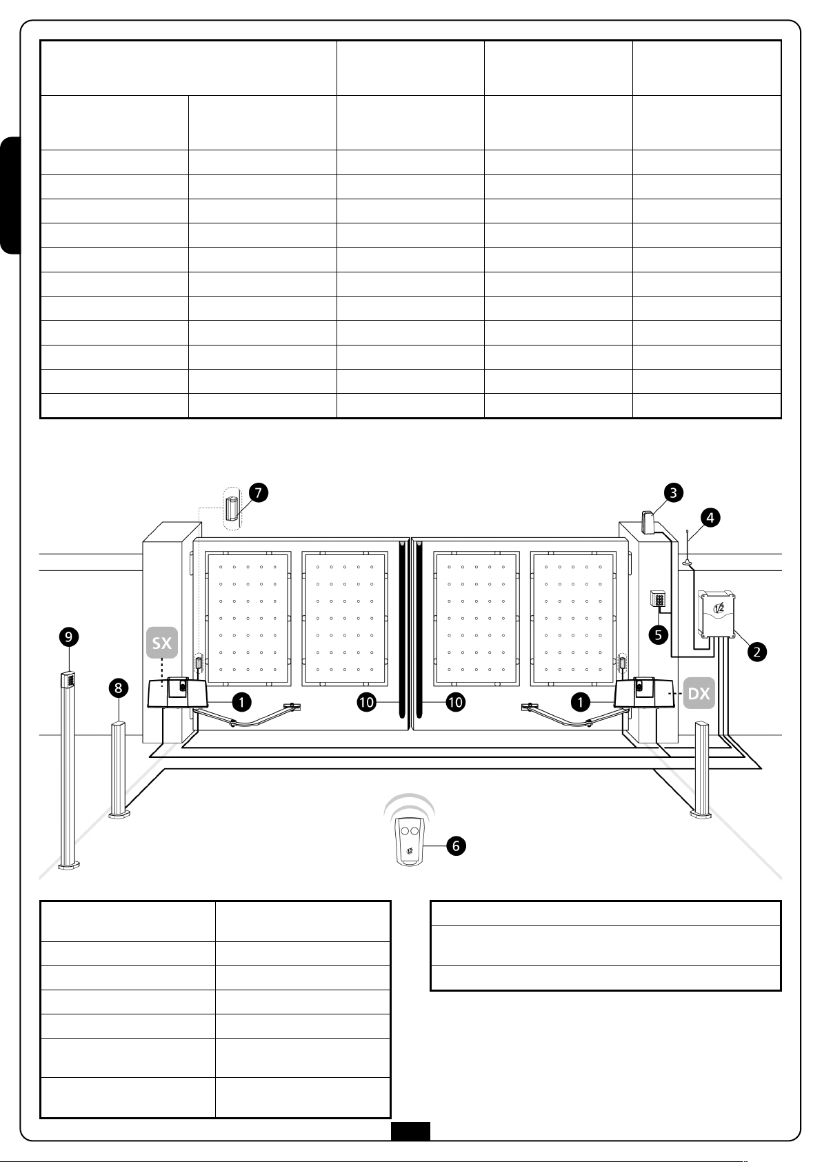
SCHEMA DI INSTALLAZIONE
3 x 500 Kg
2,5 x 600 Kg
x 800 Kg
2
,8
1
,6
1
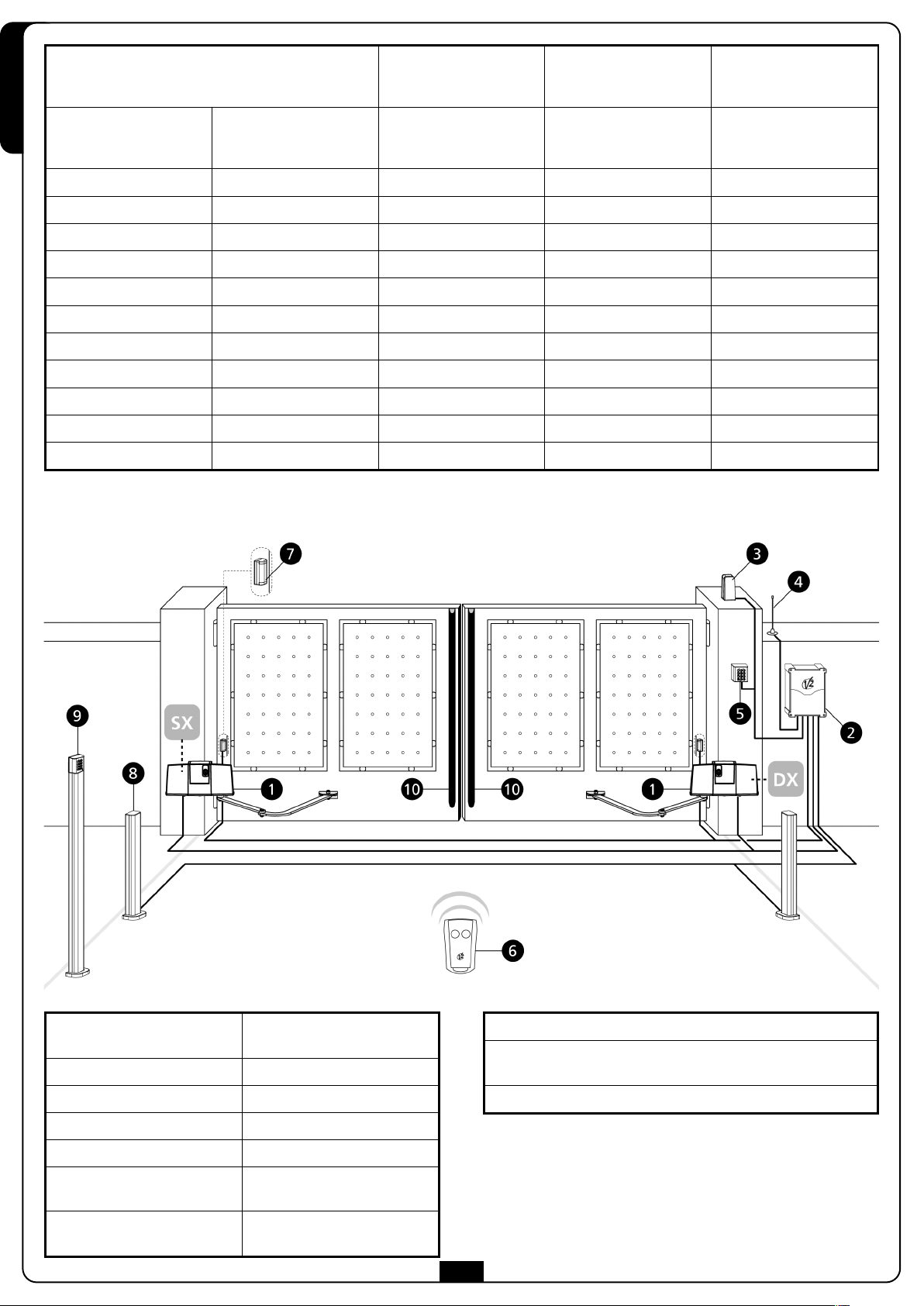
1 Attuatore BLITZ
cavo 4 x 1 mm
cavo 1,5 x 2 mm2(Blitz-24V)
2 Centrale di comando cavo 3 x 1,5 mm
3 Lampeggiante cavo 2 x 1 mm
4 Antenna cavo RG-58
5 Selettore chiave o digitale cavo 3 x 0,5 mm
6 Fotocellule esterne
7 Fotocellule interne +
colonnine GARDO50
cavo 4 x 0,5 mm2(RX)
cavo 2 x 0,5 mm
cavo 4 x 0,5 mm2(RX)
cavo 2 x 0,5 mm2(TX)
2
2
2
2
2
(TX)
8 Costa di sicurezza (EN 12978)
9 Lettore di prossimità via radio o tastierino via radio +
colonnina GARDO100
10 Trasmettitore
2
Page 5
OPERAZIONI PRELIMINARI
La nuova serie di attuatori BLITZ è stata studiata per automatizzare cancelli a battente pesanti fino a 800 Kg con ante lunghe fino a
3 m a seconda dei modelli (vedere tabella caratteristiche tecniche). Prima di procedere con l’installazione è fondamentale assicurarsi che il
vostro cancello si apra e si chiuda liberamente e verificare scrupolosamente i seguenti punti:
• cardini e perni in ottimo stato e opportunamente ingrassati
• nessun ostacolo deve impedire il movimento
• nessun attrito con il suolo e tra le ante (dilatazione meccanica da 7 a 8 mm minimi)
• il vostro cancello deve essere equipaggiato di fermo centrale (1) e possibilmente anche di fermi laterali (2).
ITALIANO
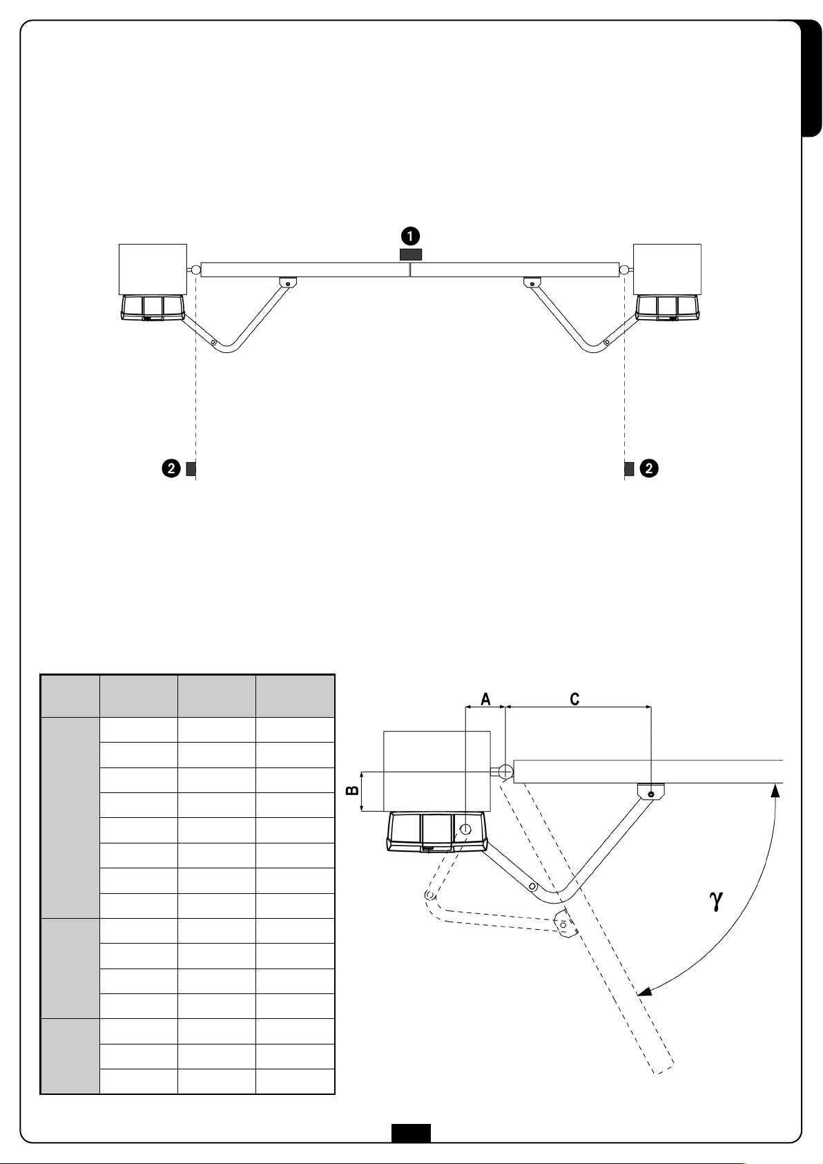
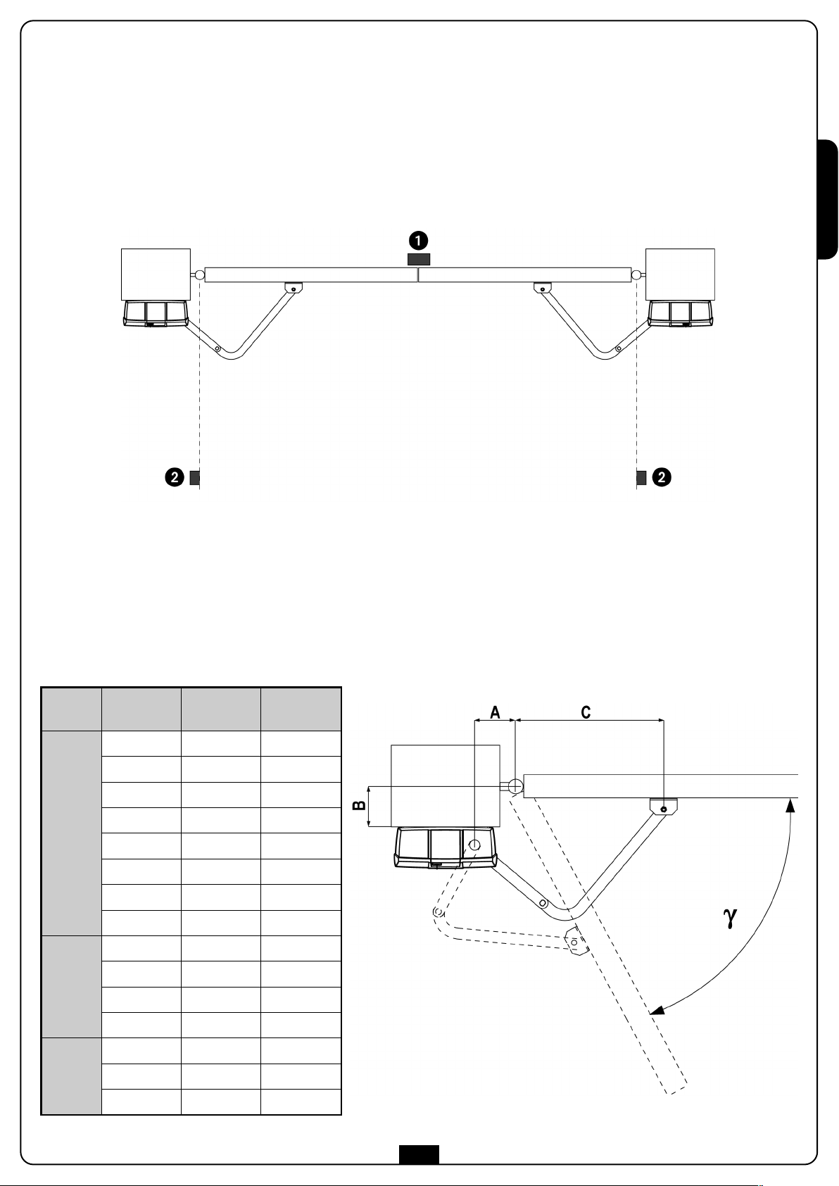
MISURE DI INSTALLAZIONE
Per effettuare una corretta installazione degli operatori e garantire un funzionamento ottimale dell’automazione è necessario rispettare le
misure riportate in tabella. Eventualmente modificare la struttura del cancello in modo da adattarlo ad uno dei casi riportati nella tabella.
γγ
B [mm] A [mm] C [mm]
20 ÷ 40 140 650
50 ÷ 80 140 650
90 ÷ 140 150 650
150 ÷ 160 160 650
90°
170 ÷ 180 180 650
180 ÷ 220 180 650
220 ÷ 250 180 600
250 ÷ 320 200 600
20 ÷ 60 170 650
70 ÷ 110 180 650
100°
110 ÷ 150 190 650
110°
150 ÷ 200 200 650
20 ÷ 50 180 650
50 ÷ 100 200 650
110 ÷ 130 210 650
3
Page 6

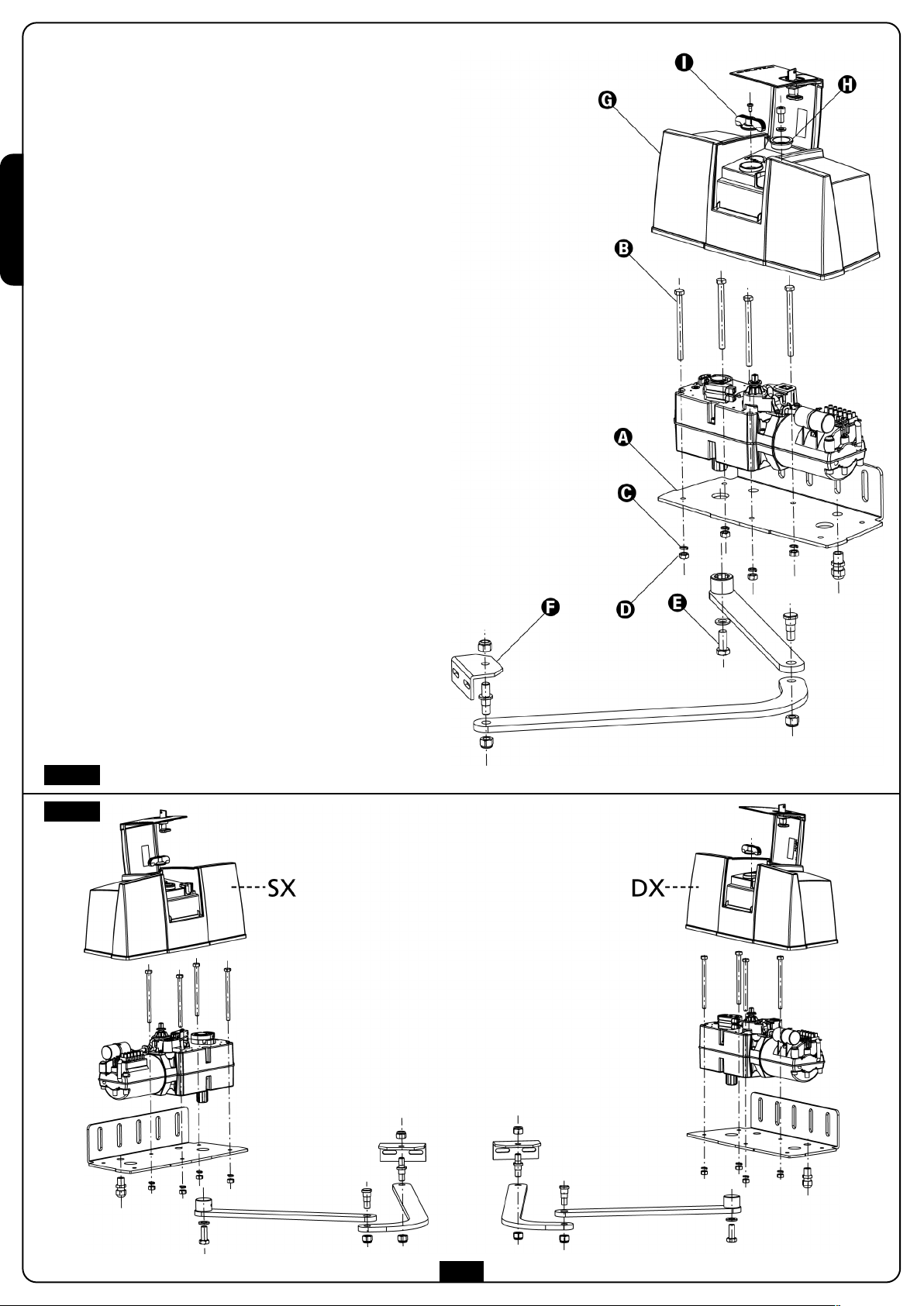
ISSAGGIO DEGLI ATTUATORI
F
Dopo aver riportato sui pilastri le misure scelte nella tabella della
pagina precedente, procedere con le seguenti operazioni,
enendo come riferimento figura 1:
t
ITALIANO
Fissare la piastra di ancoraggio
•
viti e tasselli adeguati.
• Inserire il motoriduttore nella piastra di ancoraggio e fissarlo
tilizzando le viti
u
(l'albero di rotazione deve essere rivolto verso il basso).
• Assemblare il braccio snodato e la staffa anteriore come da
igura.
f
• Innestare il braccio snodato nell'albero di rotazione e serrare
la vite
.
Sbloccare il motoriduttore (vedi paragrafo SBLOCCO DI
•
EMERGENZA).
• Riportare sull'anta i punti di fissaggio della staffa anteriore
ispettando le quote precedentemente definite.
r
• Separare la staffa anteriore
• Fissare la staffa sull'anta utilizzando delle viti, o se la
struttura e i materiali lo permettono, saldare direttamente la
staffa.
• Unire la staffa
• Provare più volte ad aprire e chiudere manualmente le ante
controllando che non ci siano attriti indesiderati.
• Procedere con i COLLEGAMENTI ELETTRICI e la
REGOLAZIONE DEI FINECORSA.
• Inserire il coperchio
e fissare le due viti.
le rondelle
,
dal braccio snodato.
al braccio snodato.
, il tappo , la maniglia di sblocco
l pilastro utilizzando le
a
e
dadi
n dotazione
i
ATTENZIONE: Per l'attuatore sinistro ripetere le
operazioni sopra descritte dopo aver posizionato il motore
come da figura 2.
Fig. 1
Fig. 2
4
Page 7
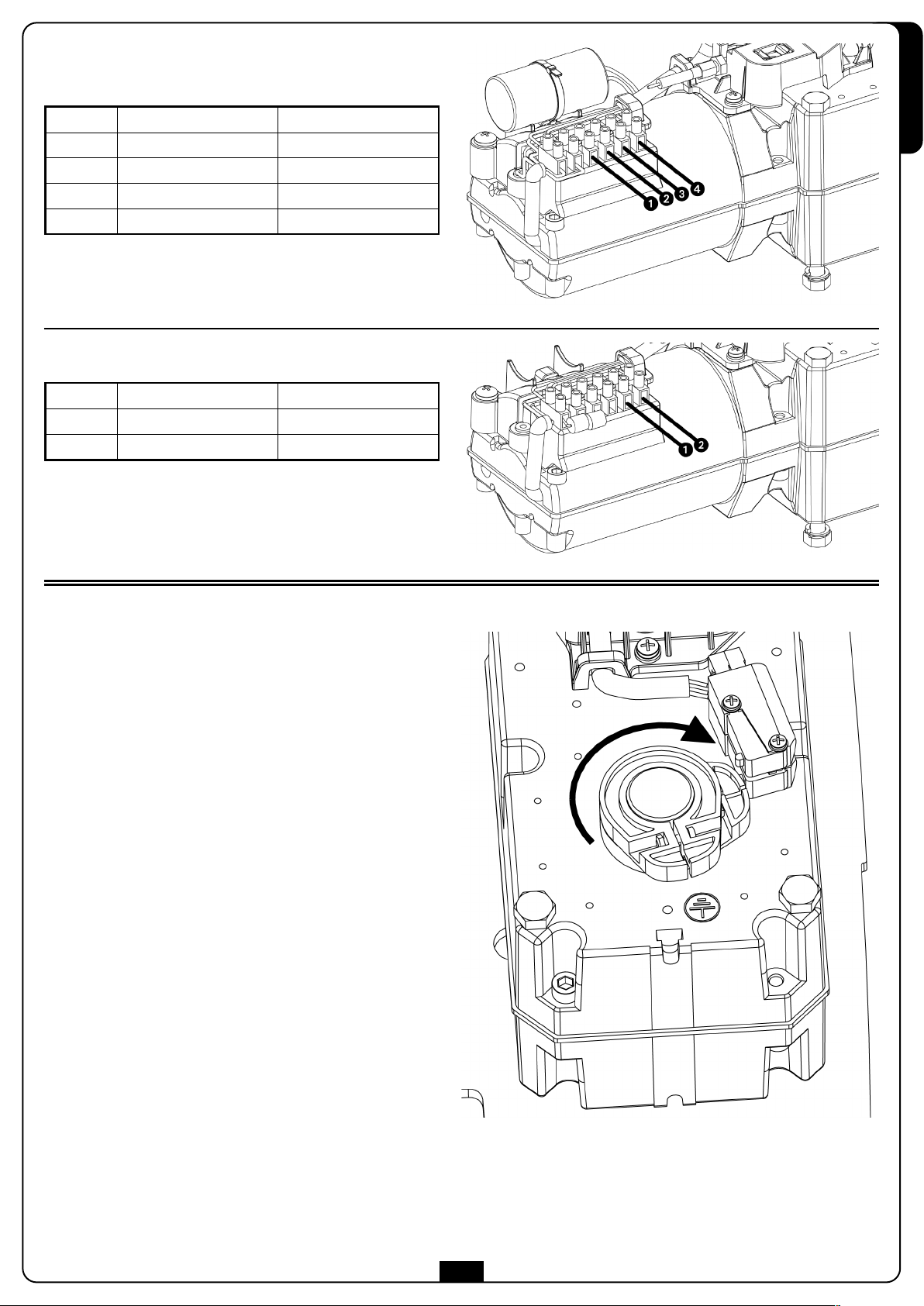
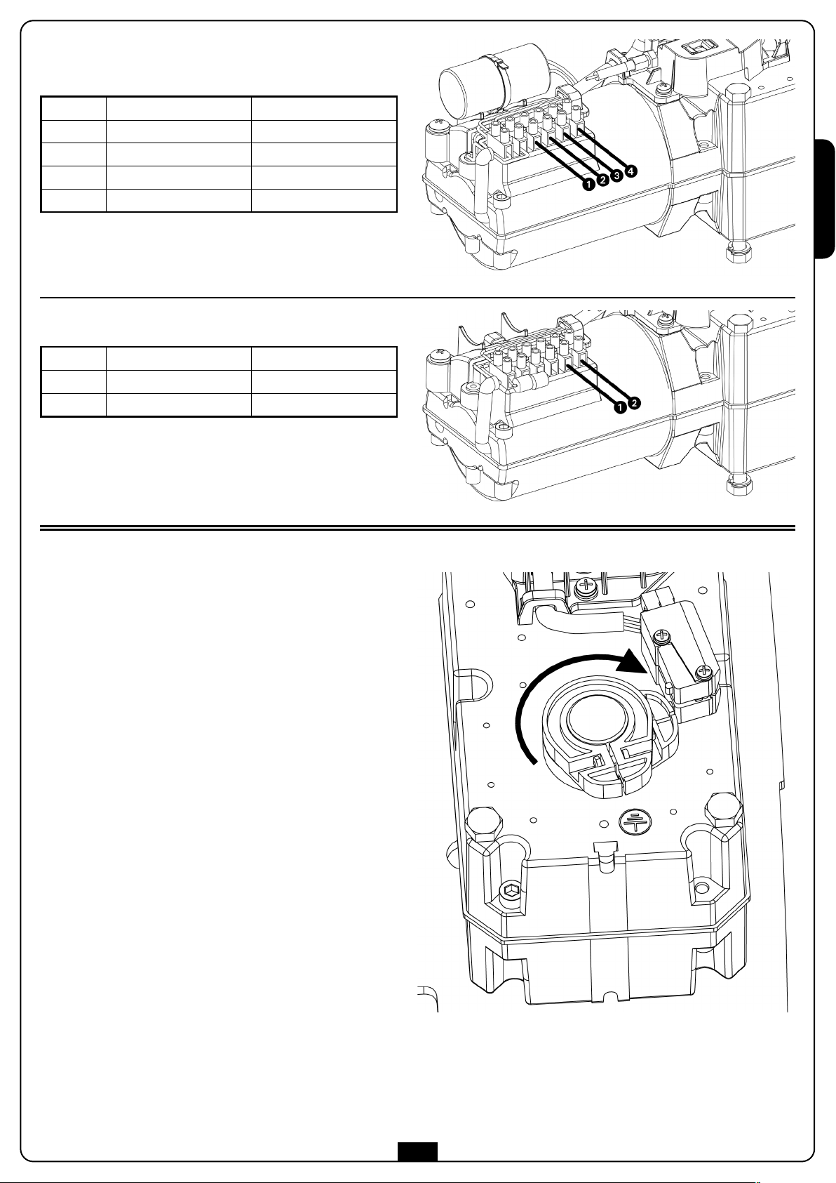
OLLEGAMENTI ELETTRICI
C
BLITZ-230V / BLITZ-120V
Rif. MOTORE sinistro (SX) MOTORE destro (DX)
GND GND
COMUNE COMUNE
APERTURA CHIUSURA
HIUSURA
C
PERTURA
A
ATTENZIONE: Collegare sempre il cavo di terra come
revisto dalle normative vigenti (EN 60335-1, EN 60204-1).
p
BLITZ-24V
Rif. MOTORE sinistro (SX) MOTORE destro (DX)
APERTURA CHIUSURA
CHIUSURA APERTURA
ITALIANO
REGOLAZIONE DEI FINECORSA
Finecorsa di apertura: sbloccare l'attuatore e portare l'anta in
posizione di apertura. Regolare la camma (INFERIORE per il
motore DESTRO e SUPERIORE per il motore SINISTRO) fino a far
inserire il microinterruttore (vedi figura).
Fissare la camma chiudendo la vite.
Finecorsa di chiusura: sbloccare l'attuatore e portare l'anta in
posizione di chiusura. Regolare la camma (SUPERIORE per il
motore DESTRO e INFERIORE per il motore SINISTRO) fino a far
inserire il microinterruttore.
Fissare la camma chiudendo la vite.
5
Page 8
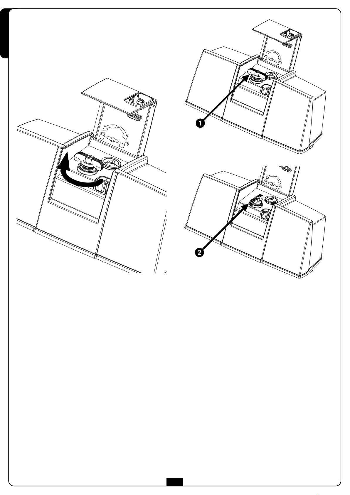
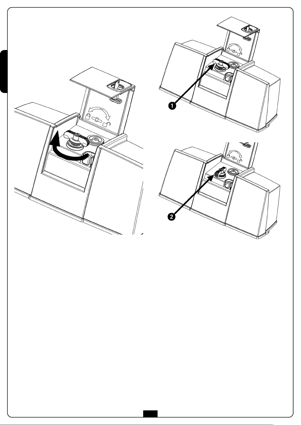
SBLOCCO DI EMERGENZA
In caso di mancanza di corrente elettrica, il cancello può essere
sbloccato meccanicamente agendo sul motore. Inserire la chiave
in dotazione e compiere 1/2 giro. Aprire lo sportello e ruotare la
ITALIANO
leva di sblocco in posizione 2. Per ripristinare l’automazione è
sufficiente ruotare nuovamente la leva di sblocco nella posizione
iniziale 1, chiudere lo sportello, girare la chiave e chiudere la
protezione plastica.
6
Page 9

IMPORTANT REMARKS
For any installation problem please contact our Customer Service
at the number +39-0172.812411 operating Monday to Friday
from 8:30 to 12:30 and from 14:00 to 18:00.
For correct installation of the system, we recommend
•
following the instructions issued by UNAC very carefully,
which can be consulted at the following web site:
www.v2home.com
V2 has the right to modify the product without previous
notice; it also declines any responsibility to damage or
injury to people or things caused by improper use or
wrong installation.
P
before installing and programming your control unit.
• This instruction manual is only for qualified technicians, who
• The contents of this instruction manual do not concern the
• Every programming and/or every maintenance service should
AUTOMATION MUST BE IMPLEMENTED IN COMPLIANCE
WITH THE EUROPEAN REGULATIONS IN FORCE:
EN 60204-1 (Machinery safety electrical equipment of
EN 12445 (Safe use of automated locking devices, test
EN 12453 (Safe use of automated locking devices,
• The installer must provide for a device (es. magnetotermical
• The plastic case has an IP55 insulation; to connect flexible
lease read this instruction manual very carefully
specialize in installations and automations.
end user.
be done only by qualified technicians.
machines, part 1: general rules)
methods)
requirements)
switch) ensuring the omnipolar sectioning of the equipment
from the power supply.
The standards require a separation of the contacts of at
least 3 mm in each pole (EN 60335-1).
or rigid pipes, use pipefittings having the same insulation
level.
DECLARATION OF CONFORMITY
The following statement is applicable only if the below listed
equipments are employed in accordance with the purpose indicated in the instruction manual.
ompany: Contact person:
C
V2 SPA Cosimo De Falco
Corso Principi di Piemonte 65 Chief Executive Officer
12035 RACCONIGI -ITALY
el. +39 01 72 82 10 11
T
Fax +39 01 72 82 10 50
V2 SPA declares that the series of BLITZ actuators are in
onformity with the provisions of the following EC directives:
c
73/23/EEC low voltage directive
89/366/CEE electromagnetic compatibility directive
98/37/EEC machine directive
Note: Declares that the above mentioned devices may not be
operated until the machine (automated gate) is identified, CElabeled, and declared to be compliant to the specifications of
Directive 89/392/EEC and following modifications.
The person in charge for the machine start-up must provide the
following records:
• Technical specification paper
• Declaration of conformity
• CE-labeling
• Testing record
• Maintenance record
• Operation manual and directions
ENGLISH
• Installation requires mechanical and electrical skills,
therefore it shall be carried out by qualified personnel only,
who can issue the Compliance Certificate concerning the
whole installation (Machine Directive 98/37/EEC, Annex IIA).
• The automated vehicular gates shall comply with the
following rules: EN 12453, EN 12445, EN 12978 as well as
any local rule in force.
• Also the automation upstream electric system shall comply
with the laws and rules in force and be carried out
workmanlike.
• The door thrust force adjustment shall be measured by
means of a proper tool and adjusted according to the max.
limits, which EN 12453 allows.
• We recommend to make use of an emergency button, to be
installed by the automation (connected to the control unit
STOP input) so that the gate may be immediately stopped
in case of danger.
• The appliance is not to be used by children or persons with
reduced physical, sensory or mental capabilities, or lack of
experience and knowledge, unless they have been given
supervision or instruction.
Racconigi 20/10/2009
V2 SPA legal representative
Cosimo De Falco
• Children being supervised do not play with the appliance.
7
Page 10
TECHNICAL SPECIFICATIONS BLITZ-24V BLITZ-120V BLITZ-230V
Max. leaf lenght m
3 x 500 Kg
2,5 x 600 Kg
x 800 Kg
2
3 x 500 Kg
2,5 x 600 Kg
x 800 Kg
2
Power supply Vac / Hz 24 Vdc 120 / 60 230 / 50
dling current
I
A 1
,5
,8
3
Full load current A 7,5 4,5 2,5
ENGLISH
Rated power W 45 400 400
Capacitor µF - 30 8
peed
S
R
pm
,4 ÷ 0,5
1
,9
1
Torque N m 320 340 340
Working temperature °C -30 ÷ +60 -30 ÷ +60 -30 ÷ +60
Thermal protection °C 140 140 140
Working cycle % 80 20 20
Motor weight Kg 14,6 14,6 14,6
INSTALLATION LAYOUT
3 x 500 Kg
2,5 x 600 Kg
x 800 Kg
2
,8
1
,6
1
1 BLITZ actuator
cable 4 x 1 mm
cable 1,5 x 2 mm2(Blitz-24V)
2 Control unit cable 3 x 1,5 mm
3 Blinker cable 2 x 1 mm
4 Aerial cable RG-58
5 Key or digital selector cable 3 x 0,5 mm
6 External photocells
7 Internal photocells +
GARDO50 pillars
cable 4 x 0,5 mm2(RX)
cable 2 x 0,5 mm
cable 4 x 0,5 mm2(RX)
cable 2 x 0,5 mm2(TX)
2
2
2
2
2
(TX)
8 Safety edge (EN 12978)
9 Proximity reader via radio or digital selector via radio +
pillar GARDO100
10 Transmitter
8
Page 11
PRELIMINARY OPERATIONS
The new series of actuadors BLITZ, has been devised to serve gates up to 800 Kg with leaf up to 3 meters wide (look at the table technical
data). Before proceeding with the installation, please make sure that your gate opens and closes freely, and that:
• Pintles and pivots shall be in good order and properly lubricated
• Nothing shall block the movement
• No friction with earth and between the doors shall exist (mechanical expansion from 7 to 8 mm min.)
• Your gate has to be equipped with central stop (1) and possibly side limits (2)
ENGLISH
INSTALLATION MEASURES
To carry out a proper installation of the operator parts as well as to ensure the best automation performance, the measurement levels
shown in the following table shall be complied with. Change the gate structure to adapt it to one of the cases in the table, if necessary.
γγ
B [mm] A [mm] C [mm]
20 ÷ 40 140 650
50 ÷ 80 140 650
90 ÷ 140 150 650
150 ÷ 160 160 650
90°
170 ÷ 180 180 650
180 ÷ 220 180 650
220 ÷ 250 180 600
250 ÷ 320 200 600
20 ÷ 60 170 650
70 ÷ 110 180 650
100°
110 ÷ 150 190 650
110°
150 ÷ 200 200 650
20 ÷ 50 180 650
50 ÷ 100 200 650
110 ÷ 130 210 650
9
Page 12
CTUATOR FASTENING
A
As soon as the measures selected from the table, which is on the
previous page, have been marked on piers, proceed with the
ollowing operations, considering figure 1 as a reference:
f
Fasten the anchor plate
•
proper screws and blocks.
• Enter the ratiomotor into the anchor plate and fasten it by
eans of screws
m
shaft must be turned downwards).
• Assembly the articulated arm and the relevant bracket as
ENGLISH
hown in the figure.
s
• Fit the articulated arm into the shaft and fasten the screw
• Release the ratiomotor (see paragraph EMERGENCY LOCK
ELEASE).
R
• Mark the front bracket fastening points on the door
according to the previous established levels.
Separate the front bracket F from the articulated arm.
•
• Fasten the bracket on the door by means of screws or
directly weld it in case the material it is made of allows it.
• Link the clamp
• Make several manual attempts in order to open and close
the doors by checking that no unwanted friction occurs.
• Proceed with ELECTRICAL CONNECTIONS and ADJUSTMENT
OF STOP ENDS.
• Insert the cap
and fix the two screws.
,
to the pivoted arm.
, the plug , the unclamping handle
o the pier by making use of
t
washers
a
nd nuts
upplied (the
s
WARNING: For the left actuator install the motor as
shown in fig.2 and repeat the above operations.
.
Fig. 1
Fig. 2
10
Page 13
LECTRICAL CONNECTIONS
E
BLITZ-230V / BLITZ-120V
Rif. Left MOTOR (SX) Right MOTOR (DX)
GND GND
COMMON COMMON
OPENING CLOSING
LOSING
C
PENING
O
WARNING: always remember to connect the earth
ccording to current standards (EN 60335-1, EN 60204-1).
a
BLITZ-24V
Rif. Left MOTOR (SX) Right MOTOR (DX)
OPENING CLOSING
CLOSING OPENING
ENGLISH
ADJUSTMENT OF STOP ENDS
Opening stop end: release the actuator and put the door into
its opening position. Adjust the cam (LOWER for the RIGHT
motor and UPPER for the LEFT motor) until the microswitch is
entered (see figure). Then fasten the cam by closing the screw.
Closing stop end: release the actuator and put the door into its
closing position. Adjust the cam (UPPER for the RIGHT motor and
LOWER for the LEFT motor) until the microswitch is entered.
Then fasten the cam by closing the screw.
11
Page 14
EMERGENCY RELEASE
In case of a blackout, the gate can be operated directly from the
motor. Insert the key supplied in the lock, perform 1/2 of a turn.
Open the door and turn the release lever to position 2. Turn
again the release lever to position 1, close the door, turn the key
and then close the plastic guard in order to restore the
automation.
ENGLISH
12
Page 15

CONSEILS IMPORTANTS
Pour tout précision technique ou problème d’installation
V2 dispose d’un Service Clients à Votre disposition du lundi au
vendredi de 8:30 à 12:30 et de 14:00 heures à 18:00 heures. au
numéro +39-0172.812411
V2 se réserve le droit d’apporter d’éventuelles
modifications au produit sans préavis; elle décline en outre
toute responsabilité pour tous types de dommages aux
personnes ou aux choses dus à une utilisation imporopre
ou à une mauvaise installation.
Avant de proceder avec l'installation et la
progarmmation, lire attentivement les notices.
• Ce manuel d'instruction est destiné à des techniciens
qualifiés dans le domain des automatismes.
• Aucune des informations contenues dans ce livret pourra
être utile pour le particulier.
• Tous operations de maintenance ou programation doivent
être faites à travers de techniciens qualifiés.
L’AUTOMATION DOIT ÊTRE RÉALISÉE CONFORMÉMENT AUX
DISPOSITIFS NORMATIFS EUROPÉENS EN VIGUEUR:
EN 60204-1 (Sécutité de la machinerie. Équipement
électriquedes machines, partie 1: régles générales).
EN 12445 (Sécutité dans lìutilisation de fermetures
automatisées, méthodes d'essai).
EN 12453 (Sécurité dans l'utilisation de fermetures
automatisées, conditions requises).
• L'installateur doit pourvoir à l'installation d'un dispositif
(ex. interrupteur magnétothermique) qui assure la coupure
omnipolaire de l'équipement du réseau d'alimentation.
La norme requiert une séparation des contacts d'au moins
3 mm pour chaque pôle (EN 60335-1).
• L'enveloppe en plastique de la carte possède une
protection IP55, pour la connexion de tubes rigides ou
flexibles utiliser des raccordements possédant le même
niveau de protection.
Veillez à ce que les enfants ne puissent jouer avec
•
l'appareillage.
• Pour une correcte mise en service du système nous
conseillons de suivre attentivement les indications fournies
par l'association UNAC trouvables dans le site web suivant :
www.v2home.com
DECLARATION DE CONFORMITÉ
La déclaration suivante s’applique seulement si les articles ci-après
ont utilisés dans le but indiqué dans le manuel d’utilisation.
s
Société : Personne à contacter :
V2 SPA Cosimo De Falco
orso Principi di Piemonte 65 Le représentant légal
C
12035 RACCONIGI -ITALY
Tel. +39 01 72 82 10 11
Fax +39 01 72 82 10 50
V2 SPA déclare que les opérateurs de la série BLITZ sont
conformes aux qualités requises par les Directives:
2006/95/CEE Directive Basse tension
89/366/CEE Directive compatibilité electromagnétique
98/37/EEC Directive machines
Nota: Déclare que n’est pas permis mettre en service les
dispositifs indiqués ci-dessous jusqu’à quand la
machine (portail automatisé) soie été identifiée, marqué CE et on
aie émise la conformité aux conditions de la Directive 89/392/EEC
et ses modifications.
Le responsable de la mise en service doit fournir les papiers
suivants:
• Dossier technique
• Déclaration de conformité
• Marque CE
• Verbal de vérification
• Registre de l’ entretien
• Notices de montages et avertissements
FRANÇAIS
• L’installation requiert des compétences en matière
d’électricité et mécaniques; doit être faite exclusivement par
techniciens qualifiés en mesure de délivrer l’attestation de
conformité pour l’installation (Directive 98/37/EEC, - IIA).
• Il est obligatoire se conformer aux normes suivantes pour
fermetures véhiculaires automatisées: EN 12453,
EN 12445, EN 12978 et à toutes éventuelles prescriptions
nationales.
• Même l’installation électrique ou on branche l’automatisme
doit répondre aux normesen vigueur et être fait à règles de
l’art.
• La régulation de la force de poussée du vantail doit être
mesurée avec outil spécial et réglée selon les valeurs maxi
admis par la norme EN 12453.
• Nous conseillons d’utiliser un poussoir d’urgence à installer
près de l’automatisme (branché à l’entrée STOP de
l’armoire de commande de façon qui soit possible l’arrêt
immédiat du portail en cas de danger.
• L'appareillage ne doit pas être utilisé par des enfants ou
des personnes affectés d'handicaps physiques et/ou
psychiques, sans la nécessaire connaissance ou
supervision de la part d'une personne compétente.
Racconigi le 20/10/2009
Le représentant dument habilité V2 SPA
Cosimo De Falco
13
Page 16

CARACTÉRISTIQUES TECHNIQUES BLITZ-24V BLITZ-120V BLITZ-230V
Longuer maxi du battant m
3 x 500 Kg
2,5 x 600 Kg
x 800 Kg
2
3 x 500 Kg
2,5 x 600 Kg
x 800 Kg
2
Alimentation Vac / Hz 24 Vdc 120 / 60 230 / 50
bsorption à vide
A
A 1
,5
,8
3
Absorption maximum A 7,5 4,5 2,5
Puissance nominal W 45 400 400
Condensateur µF - 30 8
itesse
V
R
pm
,4 ÷ 0,5
1
,9
1
Couple N m 320 340 340
Température de service °C -30 ÷ +60 -30 ÷ +60 -30 ÷ +60
FRANÇAIS
Protection thermique °C 140 140 140
Cycle de travail % 80 20 20
Poids moteur Kg 14,6 14,6 14,6
SCHÉMA D’INSTALLATION
3 x 500 Kg
2,5 x 600 Kg
x 800 Kg
2
,8
1
,6
1
1 Operateur BLITZ
câble 4 x 1 mm
câble 1,5 x 2 mm2(Blitz-24V)
2 Armoire de commande câble 3 x 1,5 mm
3 Clignotant câble 2 x 1 mm
4 Antenne câble RG-58
5 Selecteur à clé ou digital câble 3 x 0,5 mm
6 Photocellules externe
7 Photocellules interne +
columnas GARDO50
câble 4 x 0,5 mm2(RX)
câble 2 x 0,5 mm
câble 4 x 0,5 mm2(RX)
câble 2 x 0,5 mm2(TX)
2
2
2
2
2
(TX)
8 Barre palpeuse de sécurité (EN 12978)
9 Lecteur de proximité par radio o selector digital par radio +
columna GARDO100
10 Emetteur
14
Page 17

OPÉRATIONS PRÉLIMINAIRES
Ce nouvelle série des opérateurs électromécaniques BLITZ, a été crée pour automatiser portails à battant jusqu’à 800 Kg de poids et
vantail de 3 m selon les models (voir tableau caractéristiques techniques). Avant de procéder à l'installation il est fondamental de s'assurer
que votre portail s'ouvre et se referme sans problème et de vérifier scrupuleusement les points suivants:
• gonds et tourillons en très bon état et graissés de manière opportune
• aucune entrave ne doit empêcher le mouvement
• aucun frottement contre le sol et entre les volets (dilatation mécanique de 7 à 8 mm minimum)
• Votre portail doit être équipé avec arrêt central (1) et, si possible, butées latérales (2)
FRANÇAIS
MESURES D’INSTALLATION
Pour effectuer une bonne installation des actionneurs et garantir un fonctionnement optimal de l'automatisation il est nécessaire de
respecter leniveaux de mesure reproduits dans le tableau ci-dessous.Modifier le cas échéant la structure du portail de manière à l'adapter à
l'un des cas de figure énoncés dans le tableau.
γγ
B [mm] A [mm] C [mm]
20 ÷ 40 140 650
50 ÷ 80 140 650
90 ÷ 140 150 650
150 ÷ 160 160 650
90°
170 ÷ 180 180 650
180 ÷ 220 180 650
220 ÷ 250 180 600
250 ÷ 320 200 600
20 ÷ 60 170 650
70 ÷ 110 180 650
100°
110 ÷ 150 190 650
110°
150 ÷ 200 200 650
20 ÷ 50 180 650
50 ÷ 100 200 650
110 ÷ 130 210 650
15
Page 18

IXATION DES OPERATEURS
F
Après avoir tracé sur les piliers les cotes choisie dans le tableau
de la page précédente, faire les opérations suivantes en tenant
omme référence la fig. 1 :
c
Fixer la plaque support
•
boulons adéquats.
• Insérer le motoréducteur dans la plaque supporte et le fixer
n utilisant les vises
e
dotations (l’arbre de rotation doit être tourné en bas).
• Assembler le bras coudé au bras droit selon figure.
Enclancher le bras coudé dans l’arbre de rotation et serrer
•
la vis
.
• Débrayer le motoréducteur (selon paragraphe DEBRAYAGE
’URGENCE)
D
• Tracer sur le vantail les points de fixation de l’étrier antérieur
en respectant les cotes définies en avances.
Séparer l’étrier antérieur
•
• Fixer l’étrier sur le vantail en utilisant vises, ou si la
FRANÇAIS
structure et les matériaux le permettent souder directement
l’étrier.
• Joindre l'étriere
• Essayer plusieurs fois d’ouvrir et fermer de façon manuelle
les vantail, en vérifiant que il n’y aient pas des frottements.
• Procéder avec les BRANCHEMENTS ELECTRIQUES el la
REGULATION DES FIN COURSE
• Insérer le couvercle
déblocage
au bras articué.
, le bondon , le poignée de
et fixer les deux vises.
u pilier utilisant les vises et les
a
les rondelles
,
d
e
u bras coudé.
t les écrou
e
n
ATTENTION: Pour l’opérateur gauche refaire les
opérations su-décrites après avoir positionné le moteur
selon la figure 2.
Fig. 1
Fig. 2
16
Page 19

ONNEXIONS ÉLECTRIQUES
C
BLITZ-230V / BLITZ-120V
Rif. MOTEUR gauche (SX) MOTEUR droite (DX)
GND GND
COMMUN COMMUN
OUVERTURE FERMETURE
ERMETURE
F
UVERTURE
O
ATTENTION: Brancher imperativement le câble de terre
selon les Normes en vigueur (EN 60335-1, EN 60204-1).
BLITZ-24V
Rif. MOTEUR gauche (SX) MOTEUR droite (DX)
OUVERTURE FERMETURE
FERMETURE OUVERTURE
FRANÇAIS
REGLAGE DES FIN COURSE
Fin course en ouverture: débrayer l’opérateur et mettre le
vantail en position d’ouverture. Régler la came (INFERIEUR pour
le moteur DROITE et SUPERIEUR pour le moteur GAUCHE)
jusqu’à faire insérer le micro interrupteur (voir figure). Fixer la
came en fermant la vis.
Fin corse de fermeture: débrayer l’opérateur et porter le vantail
en position de fermeture. Régler la came (SUPERIEUR pour le
moteur DROITE et INFERIEUR pour le moteur GAUCHE) jusqu’à
faire insérer le micro interrupteur. Fixer la came en
fermant la vis.
17
Page 20

MANOEUVRE DE SECOURS
En cas de coupure du courant électrique, le portail peut être
débloqué en agissant sur le moteur. Introduire la clef fournie
dans la serrure qui se trouve sur le côté avant du moteur,
effectuer 1/2 de tour. Ouvrir le guichet et tourner le levier de
débrayage en position 2. Pour rétablir l’automation il est
suffisant tourner a nouveau le levier de débrayage en la position
initiale 1, fermer le guichet, Tourner la clé et fermer le capot de
protection plastique.
FRANÇAIS
18
Page 21

ADVERTENCIAS IMPORTANTES
Para cualquier problema técnico ponerse en contacto con el
Servicio Clientes V2 al número +39-0172.812411 activo de lunes
a viernes, desde las 8:30 a las 12:30 y desde las 14:00 a las 18:00.
Si necesitan ser atendidos en CASTELLANO, pueden llamar al
número +34 935809091 de lunes a viernes, desde las 9:00 a las
13:30 y desde las 15:30 a las 19:00.
La V2 se reserva el derecho de aportar eventuales
modificaciones al producto sin previo aviso; ademmás, no
se hace responsable de danos a personas o cosas debidos a
n uso improprio o a una instalación errónea.
u
Antes de proceder en las installacion y la
programmaciones aconsejable leer bien las instrucciones.
• Dicho manual es destinado exclusivamente a técnicos
calificados en las installacione de automatismos.
• Ninguna de las informacciones contenidas en dicho manual
puede ser de utilidad para el usuario final.
• Cualquiera operacion de manutencion y programacion tendrà
que ser hecha para técnicos calificados en las installacione
de automatismos.
LA AUTOMATIZACION DEBE SER REALIZADA EN
CONFORMIDAD A LAS VIGENTES NORMATIVAS EUROPEAS:
EN 60204-1 (Seguridad de la maquinaria. Equipamiento
electrico de las maquinas, partes 1: reglas
generales).
EN 12445 (Seguridad en el uso de cierres automatizados,
metodos de prueba)
EN 12453 (Seguridad en el uso de cierres automatizados,
requisitos)
• El instalador debe proveer la instalación de un dispositivo
(ej. interruptor magnetotérmico) que asegure el
seccionamiento omnipolar del aparato de la red de
alimentación. La normativa requiere una separación de los
contactos de mínimo 3 mm en cada polo (EN 60335-1).
Para una correcta puesta en servicio del sistema
•
recomendamos seguir cuidadosamente las indicaciones
expedidas por la asociación UNAC disponibles en la
siguiente dirección de Internet: www.v2home.com
DECLARACIONES DE CONFORMIDAD
La siguiente declaración sólo es aplicable si los artículos abajo
enumerados son utilizados para el fin indicado en el manual de
uso.
ociedad: Persona de contacto:
S
V2 SPA Cosimo De Falco
Corso Principi di Piemonte 65 Representante legal
12035 RACCONIGI -ITALY
el. +39 01 72 82 10 11
T
Fax +39 01 72 82 10 50
V2 SPA declara que los actuadores de la serie BLITZ son
onformes con los requisitos esenciales fijados por las Directivas:
c
2006/95/CEE Directiva de baja tensión
89/366/CEE Directiva compatibilidad electromagnetica
98/37/EEC Directiva maquinas
Nota: Se declara que no está permitido poner en
marcha los dispositivos que se detallan arriba hasta que la
maquina (puerta automatizada) haya sido identificada, sellada CE
y haya sido emitida la conformidad a las condiciones de la
Directiva 89/392/EEC y posteriores modificaciones.
El responsable de la puesta en funcionamiento tiene que entregar
la siguiente documentación:
• Manual técnico
• Declaración de conformidad
• Sellado CE
• Informe de comprobación final
• Registro de mantenimiento
• Manual de instrucciones y advertencias
ESPAÑOL
• Para la conexión de tubos rígidos o flexibles y pasacables,
utilizar manguitos conformes al grado de protección IP55
como la caja de plástico que contiene la placa.
• La instalación requiere competencias en el campo eléctrico
y mecánico; debe ser realizada únicamente por personal
cualificado en grado de expedir la declaración de
conformidad en la instalación (Directiva máquinas
98/37/EEC, anexo IIA).
• Es obligatorio atenerse a las siguientes normas para cierres
automatizados con paso de vehículos: EN 12453,
EN 12445, EN 12978 y a las eventuales prescripciones
nacionales.
• Incluso la instalación eléctrica antes de la automatización
debe responder a las vigentes normativas y estar realizada
correctamente.
• La regulación de la fuerza de empuje de la hoja debe
medirse con un instrumento adecuado y regulada de
acuerdo con los valores máximos admitidos por la
normativa EN 12453.
• El equipo no debe ser utilizado por infantes o personas con
discapacidades físicas o psíquicas, sin el debido
conocimiento o supervisión por parte de una persona
competente.
Racconigi il 20/10/2009
Rappresentante legale V2 SPA
Cosimo De Falco
• Vigile a los niños de modo que no jueguen con el equipo.
19
Page 22

CARACTERISTICAS TECNICAS BLITZ-24V BLITZ-120V BLITZ-230V
Longitud máx. hoja m
3 x 500 Kg
2,5 x 600 Kg
x 800 Kg
2
3 x 500 Kg
2,5 x 600 Kg
x 800 Kg
2
Alimentacion Vac / Hz 24 Vdc 120 / 60 230 / 50
bsorcion en vacio
A
A 1
,5
,8
3
Absorcion con carga A 7,5 4,5 2,5
Potencia nominal W 45 400 400
Condensator µF - 30 8
elocidad
V
R
pm
,4 ÷ 0,5
1
,9
1
Par N m 320 340 340
Temperatura de servicio °C -30 ÷ +60 -30 ÷ +60 -30 ÷ +60
Termoproteccion °C 140 140 140
Ciclo de trabajo % 80 20 20
Peso del motor Kg 14,6 14,6 14,6
ESPAÑOL
ESQUEMA DE INSTALACIÓN
3 x 500 Kg
2,5 x 600 Kg
x 800 Kg
2
,8
1
,6
1
1 Actuador BLITZ
cable 4 x 1 mm
cable 1,5 x 2 mm2(Blitz-24V)
2 Cuadro de maniobras cable 3 x 1,5 mm
3 Lámpara de señalización cable 2 x 1 mm
4 Antena cable RG-58
5 Selector a llave o digital cable 3 x 0,5 mm
6 Fotocélulas externas
7 Fotocélulas internas +
columnas GARDO50
cable 4 x 0,5 mm2(RX)
cable 2 x 0,5 mm
cable 4 x 0,5 mm2(RX)
cable 2 x 0,5 mm2(TX)
2
2
2
2
2
(TX)
8 Banda de seguridad (EN 12978)
9 Lector de proximidad vía radio / Selector digital vía radio +
columna GARDO100
10 Emisor
20
Page 23

OPERACIONES PRELIMINARES
La nueva serie de operadores BLITZ ha sido estudiada para automatizar cancelas batientes pesadas hasta 800 Kg, con longitud de hoja
hasta 3 m según las versiones (ver tabla características técnicas).
Antes de proceder con la instalación, es fundamental asegurarse de que vuestra cancela abra y cierre libremente y verificar los siguientes
puntos:
• bisagras y pernios en estado óptimo y oportunamente lubricados
• ningún obstáculo debe impedir el movimiento
• ningún roce entre el suelo y las hojas (dilatación mecánica de 7 a 8 mm mín.)
• vuestra puerta tiene que haber un tope central (1) y, posiblemente, topes laterales (2)
ESPAÑOL
MEDIDAS DE INSTALACION
Para efectuar una correcta instalación de los operadores y garantizar un funcionamiento óptimo de la automatización, es necesario
respetar las cotas de medición de la tabla. Eventualmente, modificar la estructura de la puerta, de forma que se adapte a uno de los casos
de la tabla de abajo.
γγ
B [mm] A [mm] C [mm]
20 ÷ 40 140 650
50 ÷ 80 140 650
90 ÷ 140 150 650
150 ÷ 160 160 650
90°
170 ÷ 180 180 650
180 ÷ 220 180 650
220 ÷ 250 180 600
250 ÷ 320 200 600
20 ÷ 60 170 650
70 ÷ 110 180 650
100°
110 ÷ 150 190 650
110°
150 ÷ 200 200 650
20 ÷ 50 180 650
50 ÷ 100 200 650
110 ÷ 130 210 650
21
Page 24

ONTAJE DE LOS OPERADORES
M
Después de haber trazado en los postes las medidas elegidas en
la tabla de la página precedente, proceder con las siguientes
peraciones:
o
Fijar la placa de anclaje
•
tacos adecuados.
• Introducir el motorreductor en la placa de anclaje y fijarlo
tilizando los tornillos
u
en dotación (el eje de rotación tiene que estar hacia abajo).
• Montar el brazo articulado y el soporte anterior como en la
igura.
f
• Introducir el brazo articulado en el eje de rotación y apretar
el tornillo
Desbloquear el motorreductor (ver párrafo DESBLOQUEO DE
•
EMERGENCIA).
• Marcar en la hoja los puntos de fijación del soporte anterior
espetando las cuotas anteriormente definidas.
r
• Separar el soporte anterior
• Fijar el soporte a la hoja utilizando unos tornillos, o si la
estructura y los materiales lo permiten, soldar directamente
el soporte.
• Juntar l'abrazadera
• Probar más veces a abrir y cerrar manualmente las hojas
controlando que no hayan roces indeseados.
• Proceder con las CONEXIONES ELÉCTRICAS y la
ESPAÑOL
REGULACION DE LOS FINALES DE CARRERA.
• Insertar la tapa
y fijar los dos tornillos.
.
al brazo articulado.
, el tapòn , el tirador de desbloqueo
l poste utilizando los tornillos y
a
las arandelas
,
las tuercas
y
del brazo articulado.
CUIDADO: Para el actuador izquierdo repetir las
operaciones descritas arriba después de haber posicionado
el motor como en la figura 2.
Fig. 1
Fig. 2
22
Page 25

ONEXIONES ELÉCTRICAS
C
BLITZ-230V / BLITZ-120V
Rif. MOTOR izquierdo (SX) MOTOR derecho (SX)
GND GND
COMUNE COMUNE
APERTURA CIERRE
IERRE
C
PERTURA
A
ATENCION: Conectar siempre el cable de tierra segun
as Normativas vigentes (EN 60335-1, EN 60204-1)
l
BLITZ-24V
Rif. MOTOR izquierdo (SX) MOTOR derecho (SX)
APERTURA CIERRE
CIERRE APERTURA
ESPAÑOL
REGULACION DE LOS FINALES DE CARRERA
Final de carrera de apertura: desbloquear el actuador y abrir
completamente la hoja. Regular el aro de plástico (INFERIOR por
el motor DERECHO y SUPERIOR por el motor IZQUIERDO) hasta
oír el clic del micro interruptor (ver figura). Fijar el aro de plástico
apretando el tornillo.
Final de carrera de cierre: desbloquear el actuador y cerrar
completamente la hoja. Regular el aro de plástico (SUPERIOR por
el motor DERECHO y INFERIOR por el motor IZQUIERDO) hasta
oír el clic del micro interruptor. Fijar el aro de plástico apretando
el tornillo.
23
Page 26

DESBLOQUEO DE EMERGENCIA
En caso de falta de corriente eléctrica, la puerta puede ser
desbloqueada interviniendo sobre el motor. Insertar la llave en
dotación en la cerradura presente en el lado frontal del motor y
realizar 1/2 de giro. Abrir la puertecita y girar la palanca de
desbloqueo en posición 2. Para reanudar la automatización es
suficiente girar otra vez la palanca de desbloqueo en la posición
inicial 1, cerrar la puerta, girar la llave y cerrar la protección
plástica.
ESPAÑOL
24
Page 27

AVISOS IMPORTANTES
Para esclarecimentos técnicos ou problemas de instalação a V2
dispõe de um serviço de assistência clientes activo em horário de
abertura. TEL. (+39) 01 72 81 24 11
V2 reserva-se o direito de efectuar eventuais alterações ao
produto sem aviso prévio; declina ainda qualquer
responsabilidade pelos danos a pessoas ou coisas
originados por uso impróprio ou instalação errada.
• Se o cabo de alimentação estiver danificado, a sua
substituição deverá ser feita pelo fabricante, pelo seu
serviço de assistência ou, em todo caso, por pessoa com
qualificação similar, de maneira a prevenir qualquer risco.
• Para uma correta colocação em serviço do sistema
recomendamos observar cuidadosamente as indicações
fornecidas pela associação UNAC e disponibilizadas no
seguinte endereço Internet: www.v2home.com
LER ATENTAMENTE O SEGUINTE MANUAL DE
INSTRUÇÕES ANTES DE PROCEDER À INSTALAÇÃO.
• O presente manual de instruções destina-se exclusivamente
ao pessoal técnico qualificado no sector das instalações de
automações.
• Nenhuma das informações contidas no manual pode ser
interessante o útil ao utilizador final.
Qualquer operação de manutenção ou de programação
•
deve ser realizada exclusivamente por pessoal qualificado.
A AUTOMAÇÃO DEVE SER REALIZADA EM CONFORMIDADE
COM AS NORMAS EUROPEIAS VIGENTES:
EN 60204-1 (Segurança das máquinas, equipamento
eléctrico das máquinas, parte 1: regras gerais).
EN 12445 (Segurança nos cerramentos automatizados,
métodos de teste).
EN 12453 (Segurança no uso de cerramentos
automatizados, requisitos).
• O instalador deve instalar um dispositivo (ex. interruptor
térmico magnético), que assegure o seccionamento de
todos os pólos do sistema da rede de alimentação.
As normas exigem uma separação dos contactos de pelo
menos 3 mm em cada polo (EN 60335-1).
• Para a conexão dos tubos rijos e flexíveis ou passador de
cabos, utilizar junções conformes ao grau de protecção IP55
ou superior.
• A instalação requer competências no sector eléctrico e
mecânico; só deve ser efectuada por pessoal qualificado
habilitado a passar a declaração de conformidade de tipo A
para a instalação completa (Directriz máquinas 98/37/EEC,
apenso IIA).
• É obrigatório respeitar as seguintes normas para
cerramentos veiculares automatizados: EN 12453,
EN 12445, EN 12978 e as eventuais prescrições nacionais.
CONFORMIDADE COM AS NORMAS
A seguinte declaração aplica-se apenas se os artigos abaixo discriminados forem utilizados de acordo com o fim indicado no
anual de instruções.
m
Empresa: Pessoa a contactar:
V2 SPA Cosimo De Falco
orso Principi di Piemonte 65 O representante legal
C
12035 RACCONIGI -ITALY
Tel. +39 01 72 82 10 11
Fax +39 01 72 82 10 50
V2 SPA declara que os actuadores da série BLITZ são conformes
aos requisitos essenciais estabelecidos nas seguintes Directivas:
2006/95/CEE Directiva Baixa Tensão
89/366/CEE Directiva compatibilidade electromagnética
98/37/EEC Directiva máquinas
Nota: Declara que não é permitido colocar em serviço os
dispositivos acima listados antes da máquina (portão
automatizado) ser identificada e marcada CE, e antes que seja
emitida a sua declaração de conformidade às condições da
Directriz 89/392/EEC e sucessivas alterações.
O responsável da colocação em serviço deve fornecer os
seguintes documentos:
• Dossiê técnico
• Declaração de conformidade
• Marca CE
• Acta de teste
• Registo da manutenção
• Manual de instruções e avisos
Racconigi aos 20/10/2009
Representante legal V2 SPA
Cosimo De Falco
PORTUGUÊS
• A instalação a montante da automação também deve
respeitar as normas vigentes e ser realizadas conforme as
regras da arte.
• A regulação da força de impulso da folha deve medir-se
com ferramenta própria e ser regulada conforme os valores
máximos admitidos pela norma EN 12453.
• Aconselhamos utilizar um botão de emergência, a ser
instalado nas proximidades da automação, (conectado com
a entrada STOP da placa de comando) de maneira que seja
possível parar imediatamente o portão no caso de perigo.
• A aparelhagem não deve ser utilizada por crianças ou
pessoas com deficiências físicas ou psíquicas sem o devido
conhecimento ou supervisão de pessoa competente.
• Não deixe as crianças brincarem com a aparelhagem.
25
Page 28

CARACTERÍSTICAS TÉCNICAS BLITZ-24V BLITZ-120V BLITZ-230V
Comprimento máximo porta m
3 x 500 Kg
2,5 x 600 Kg
x 800 Kg
2
3 x 500 Kg
2,5 x 600 Kg
x 800 Kg
2
3 x 500 Kg
2,5 x 600 Kg
x 800 Kg
2
Energia Eléctrica Vac / Hz 24 Vdc 120 / 60 230 / 50
bsorção a vácuo
A
A 1
,5
,8
3
,8
1
Absorção máxima A 7,5 4,5 2,5
Potência nominal W 45 400 400
Condensador µF - 30 8
elocidade de rotação
V
R
pm
,4 ÷ 0,5
1
,9
1
,6
1
Dupla N m 320 340 340
Température de fonctionnement °C -30 ÷ +60 -30 ÷ +60 -30 ÷ +60
Protecção térmica °C 140 140 140
Ciclo de trabalho % 80 20 20
Peso motor Kg 14,6 14,6 14,6
ESQUEMA DE INSTALAÇÃO
PORTUGUÊS
1 Actuador BLITZ
2 Armoire de commande cabo 3 x 1,5 mm
3 Intermitência cabo 2 x 1 mm
cabo 4 x 1 mm
cabo 1,5 x 2 mm2(Blitz-24V)
2
2
2
8 Banda de seguridad (EN 12978
9 Leitor de proximidade por rádio / Selector digital por rádio +
coluna GARDO100
10 Emissor
4 Antena cabo RG-58
5 Selector com chave ou digital cabo 3 x 0,5 mm
6 Células fotoeléctricas externas
7 Células fotoeléctricas internas
+ colunas GARDO50
cabo 4 x 0,5 mm2(RX)
cabo 2 x 0,5 mm
cabo 4 x 0,5 mm2(RX)
cabo 2 x 0,5 mm2(TX)
2
2
(TX)
26
Page 29

OPERAÇÕES PRELIMINARES
A nova série de actuadores BLITZ foi estudada para automatizar portões a batente com peso de até 800 Kg, com folhas de até 3m de
comprimento, consoante os modelos (ver tabela características técnicas). Antes de iniciar a instalação é fundamental apurar que o portão
se abre e fecha livremente e verificar escrupulosamente os seguintes pontos:
• Dobradiças e pinos em óptimo estado e bem lubrificados.
• Não deve existir nenhum empecilho a impedir o movimento.
• Não deve haver nenhum atrito com o solo e entre as folhas.
• O portão deve ser dotado de paragem central(1) e possivelmente também de paragens laterais (2).
MEDIDAS DE INSTALAÇÃO
Para efectuar uma correcta instalação dos operadores e garantir um funcionamento perfeito da automatização, é necessário respeitar as
cotas de medição referidas na tabela abaixo.
Eventualmente, modificar a estrutura do portão de maneira a adaptá-lo a um dos casos referidos na tabela abaixo.
γγ
B [mm] A [mm] C [mm]
20 ÷ 40 140 650
50 ÷ 80 140 650
90 ÷ 140 150 650
150 ÷ 160 160 650
90°
170 ÷ 180 180 650
180 ÷ 220 180 650
220 ÷ 250 180 600
250 ÷ 320 200 600
PORTUGUÊS
100°
110°
20 ÷ 60 170 650
70 ÷ 110 180 650
110 ÷ 150 190 650
150 ÷ 200 200 650
20 ÷ 50 180 650
50 ÷ 100 200 650
110 ÷ 130 210 650
27
Page 30

IXAÇÃO DOS ACTUADORES
F
Após ter marcado nos pilares as medidas escolhidas na tabela da
página anterior, proceder com as seguintes operações, a ter
omo referência a figura 1:
c
• Fixar a chapa de ancoragem
e calços adequados.
• Inserir o motorredutor na chapa de ancoragem e fixá-lo com
os parafusos
árvore de rotação deve estar virada para baixo).
• Montar o braço articulado e o estribo anterior como indicado
na figura.
• Inserir o braço articulado na árvore de rotação e apertar o
parafuso
• Desbloquear o motorredutor (ver parágrafo DESBLOQUEIO
DE EMERGÊNCIA).
• Marcar na folha os pontos de fixação do estribo anterior
respeitando as cotas precedentemente definidas.
• Afastar o estribo anterior
• Fixar o estribo na folha com os parafusos, ou soldar
directamente o estribo quando a estrutura e os materiais o
permitem.
• Unir o estribo
• Tentar várias vezes abrir e fechar manualmente as folhas,
verificando que não existam atritos inoportunos.
• Proceder com as LIGAÇÕES ELÉCTRICAS e
a REGULAÇÃO DAS PARAGENS.
• Inserir a tampa
fixar os dois parafusos.
, as anilhas e as porcas fornecidas (a
.
ao braço articulado.
, a tampa , a pega de desbloqueio e
ao pilar, a utilizar parafusos
do braço articulado.
ATENÇÃO: Para o actuador esquerdo repetir as
operações acima descritas após ter posicionado o motor
como mostrado na figura 2.
PORTUGUÊS
Fig. 1
Fig. 2
28
Page 31

IGAÇÕES ELÉCTRICAS
L
BLITZ-230V / BLITZ-120V
Rif. MOTOR esquerdo (SX) MOTOR direito (DX)
GND GND
COMUN COMUN
ABERTURA FECHADURA
ECHADURA
F
BERTURA
A
ATENÇÃO: Ligar sempre o cabo de terra como previsto
elas normativas vigentes (EN 60335-1, EN 60204-1).
p
BLITZ-24V
Rif. MOTOR esquerdo (SX) MOTOR direito (DX)
ABERTURA FECHADURA
FECHADURA ABERTURA
REGULAÇÃO DAS PARAGENS
Paragens de abertura: desbloquear o actuador e colocar a
folha na posição de abertura. Regular o excêntrico (INFERIOR
para o motor DIREITO e SUPERIOR para o motor ESQUERDO) até
inserir o microinterruptor (ver figura).
Fixar o excêntrico com o parafuso.
Paragens de fechadura: desbloquear o actuador e colocar a
folha na posição de fechadura. Regular o excêntrico (SUPERIOR
para o motor DIREITO e INFERIOR para o motor ESQUERDO) até
inserir o microinterruptor.
Fixar o excêntrico com o parafuso.
PORTUGUÊS
29
Page 32

DESBLOQUEIO DE EMERGÊNCIA
No caso de interrupção da corrente eléctrica, o portão pode ser
desbloqueado mecanicamente a actuar no motor. Inserir a chave
fornecida e dar 1/2 giro. Abrir a portinhola e girar o botão de
desbloqueio até a posição 2. Para rearmar a automação basta
girar novamente o botão de desbloqueio até a posição inicial 1,
fechar a portinh ola, girar a chave e fechar a protecção plástica.
PORTUGUÊS
30
Page 33

WICHTIGE HINWEISE
Für tecnische Erläuterungen oder Installtionsprobleme verfügt die
Firma V2 SPA über einen Kundendienst, der zu Bürozeiten unter
der Telefonnummer (+39) 01 72 81 24 11 erreicht werden kann.
Die Firma V2 SPA behält sich das Recht vor, das Produkt
ohne vorherige Ankündigungen abzuändern; die
Übernahme der Haftung für Schäden an Personen oder
Sachen, die auf einen unsachgemäßen Gebrauch oder eine
fehlerhafte Installation zurückzuführen sind, wird
abgelehnt.
Kinder so beaufsichtigen, dass sie nicht mit dem Gerät spielen.
•
• Für eine korrekte Inbetriebnahme des Systems empfehlen wir,
aufmerksam die von der Vereinigung UNAC herausgegebenen
Hinweise zu befolgen, die Sie auf der Webseite
www.v2home.com finden.
KONFORMITÄTSERKLÄRUNG
Folgende Erklärung ist nur anwendbar, wenn die unten
aufgeführten Artikel zu dem im Bedienungshandbuch
ufgeführten Zweck benutzt werden.
a
Um die Steuerung fehlerfrei zu installieren und
programmieren zu können, lesen Sie bitte diese
edienungsanleitung sehr aufmerksam durch.
B
• Diese Bedienungsanleitung ist nur für Fachtechniker, die auf
Installationen und Automationen von Toren.
• Keine Information dieser Bedienungsanleitung ist für den
ndbenutzer nützlich.
E
• Jede Programmierung und/oder jede Wartung sollte nur von
geschulten Technikern vorgenommen werden.
DIE AUTOMATISIERUNG MUSS IN ÜBEREINSTIMMUNG MIT
DEN GELTENDEN EUROPÄISCHEN NORMEN ERFOLGEN:
EN 60204-1 (Sicherheit der Maschine elektrische
Ausrüstungen von Maschinen, Teil 1: allgemeine
Anforderungen)
EN 12445 (Nutzungssicherheit kraftbetätigter Tore
rüfverfahren)
EN 12453 (Nutzungssicherheit kraftbetätigter Tore
Anforderungen)
• Der Installateur muss eine Vorrichtung (z.B. thermomagn.
Schalter) anbringen, die Trennung aller Pole des Geräts zum
Versorgungsnetz garantiert. Die Norm verlangt eine Trennung
der Kontakte von mindestens 3 mm an jedem Pol (EN 60335-1).
• Für den Anschluss von Rohren und Schläuchen oder
Kabeldurchgängen sind Verbindungen zu verwenden, die dem
Sicherungsgrad IP55 entsprechen.
• Die Installation erfordert Kenntnisse auf den Gebieten der
Elektrik und Mechanik; sie darf ausschließlich von
kompetentem Personal durchgeführt werden, welches
berechtigt ist, eine vollständige Konformitätserklärung vom
Typ A auszustellen (Maschinenrichtlinie 98/37/EEC, Anlage IIA).
Gesellschaft: Kontaktperson:
V2 SPA Cosimo De Falco
orso Principi di Piemonte 65 Gesetzlicher Vertreter
C
12035 RACCONIGI -ITALY
Tel. +39 01 72 82 10 11
Fax +39 01 72 82 10 50
V2 SPA erklärt daß die Antriebe der Serie BLITZ den folgenden
Richtlinien entsprechen:
2006/95/CEE Niederspannungsrichtlinie
89/366/CEE EMC-Richtlinie
98/37/EEC Maschinenrichtlinie
Anmerkung: Legt fest, dass die oben aufgeführten Vorrichtungen
erst in Betrieb genommen werden dürfen, nachdem die Anlage
(Automatiktor) identifiziert und CE-gekennzeichnet, bzw. die
Konformität mit den Anforderungen der Richtlinie 89/392/EWG
einschl. nachfolgender Änderungen erklärt wurde.
Der Verantwortliche der Inbetriebnahme muss folgende
Dokumentation vorlegen:
• Technisches Datenheft
• Konformitätserklärung
• CE-Zertifizierung
• Prüfprotokoll
• Wartungsheft
• Benutzerhandbuch und Gebrauchshinweise
Racconigi, den 20/10/2009
Der Rechtsvertreter der V2 SPA
Cosimo De Falco
DEUTSCH
• Für automatisch betriebene Rolltore ist die Einhaltung der
folgenden Normen obligatorisch: EN 12453, EN 12445,
EN 12978 und alle eventuell geltenden, regionalen
Vorschriften.
• Auch die elektrische Anlage der Automatik muss den
geltenden Normen genügen, und fachgerecht installiert
werden.
• Die Schubkraft des Torflügels muss mit Hilfe eines
geeigneten Instruments gemessen, und entsprechend den in
Richtlinie EN 12453 definierten Höchstwerten eingestellt
werden.
• Es wird empfohlen, in der Nähe der Automatik einen NotausSchalter zu installieren (mit Anschluss an en Eingang STOP
der Steuerkarte), so dass bei Gefahr ein unverzügliches
Halten des Tors bewirkt werden kann.
• Das Gerät darf nicht von körperlich oder psychisch
behinderten Kindern oder Personen ohne entsprechende
Kenntnisse oder Aufsicht seitens einer kompetenten Person
betätigt werden.
31
Page 34

TECHNISCHE EIGENSCHAFTEN BLITZ-24V BLITZ-120V BLITZ-230V
Max. Torflügelweite m
3 x 500 Kg
2,5 x 600 Kg
x 800 Kg
2
3 x 500 Kg
2,5 x 600 Kg
x 800 Kg
2
3 x 500 Kg
2,5 x 600 Kg
x 800 Kg
2
Versongung Vac / Hz 24 Vdc 120 / 60 230 / 50
tromaufnahme ohne Belastung
S
A 1
,5
,8
3
,8
1
Maximale Stromaufnahme A 7,5 4,5 2,5
Nominalleistung W 45 400 400
Kondensator µF - 30 8
schwindigkeit
E
R
pm
,4 ÷ 0,5
1
,9
1
,6
1
Drehmoment N m 320 340 340
Betriebstemperatur °C -30 ÷ +60 -30 ÷ +60 -30 ÷ +60
Wärmeschutz °C 140 140 140
Arbeitszyklus % 80 20 20
Motorgewicht Kg 14,6 14,6 14,6
INSTALLATIONSPLAN
DEUTSCH
1 Stellantrieben BLITZ
2 Steuerung Kabel 3 x 1,5 mm
3 Blinkvorrichtung Kabel 2 x 1 mm
4 Antenne Kabel RG-58
5 Schlüssel- oder Digitalwähler Kabel 3 x 0,5 mm
6 Außenfotozellen
7 Innenfotozellen +
Säulen GARDO50
Kabel 4 x 1 mm
Kabel 1,5 x 2 mm2(Blitz-24V)
Kabel 4 x 0,5 mm2(RX)
Kabel 2 x 0,5 mm
Kabel 4 x 0,5 mm2(RX)
Kabel 2 x 0,5 mm2(TX)
2
2
2
2
2
(TX)
8 Sicherheitskontaktleisten (EN 12978)
9 Leseeinheit (Funkversion) oder Digitalwähler (Funkversion) +
Säule GARDO100
10 Sender
32
Page 35

VORBEREITNDE ARBEITSSCHRITTE
Die neue Serie von Antrieben BLITZ ist „geboren“ um Flügeltore bis 800 Kg und mit Tor-Flügeln bis 3 Meter Länge zu führen. (Bitte
sehen Sie in die Tafel mit den technischen Daten).
Vor der Installation muss sichergestellt werden, dass sich das Tor hindernisfrei öffnen und schließen lässt, ferner ist es auf
folgendeVoraussetzungen zu prüfen:
• Angeln und Stifte müssen sich in einwandfreiem Zustand befinden und hinreichend geschmiert sein
• kein Hindernis darf die Bewegung beeinträchtigen
• es darf keine Reibung zwischen den Torflügeln und dem Grund bestehen (mechanische Ausdehnung mindestens 7-8 mm)
• Ihr Tor muss mit mittlerer Sperre (1) und möglicherweise auch mit Seitenfeststellern (2) ausgerüstet sein.
INSTALLATION
Um eine korrekte Installation der Operatoren zu gewährleisten und ein optimales Funktionieren der Automatik zu garantieren, müssen
die in der untenstehenden Tabelle aufgeführten Höhenangaben genau beachtet werden.
Es könnte sich eventuell als notwendig erweisen, die Torstruktur zu verändern, um sie an eine der hier aufgeführten Konstellationen
anzupassen.
γγ
B [mm] A [mm] C [mm]
20 ÷ 40 140 650
50 ÷ 80 140 650
90 ÷ 140 150 650
150 ÷ 160 160 650
90°
170 ÷ 180 180 650
180 ÷ 220 180 650
220 ÷ 250 180 600
250 ÷ 320 200 600
20 ÷ 60 170 650
70 ÷ 110 180 650
100°
110 ÷ 150 190 650
DEUTSCH
110°
150 ÷ 200 200 650
20 ÷ 50 180 650
50 ÷ 100 200 650
110 ÷ 130 210 650
33
Page 36

EFESTIGUNG DER STELLANTRIEBE
B
Nach dem Markieren an den Säulen der in der Tabelle der
vorangehenden Seite gewählten Maße unter Berücksichtigung
on Abb. 1 wie folgt vorgehen:
v
Verankerungsplatte
•
passenden Schrauben und Dübel befestigen.
• Den Getriebemotor in die Verankerungsplatte einsetzen und
iesen unter Verwendung der mitgelieferten Schrauben
d
der Unterlegscheiben und der Muttern befestigen (Die
Drehwelle muss nach unten gerichtet sein).
Den Gelenkarm und den vorderen Bügel wie in der Abb.
•
zusammenbauen.
• Den Gelenkarm in die Drehwelle einsetzen und die
chrauben
S
• Den Getriebemotor entsperren (siehe Paragraph
ENTSPERREN IM NOTFALL).
Die Befestigungspunkte des vorderen Bügels an den Torflügel
•
ansetzen und die vorher festgelegten Höhen berücksichtigen.
• Den vorderen Bügel
• Den Bügel am Torflügel mit Schrauben befestigen, oder, wenn
die Struktur und die Materialien es erlauben, besagten Bügel
direkt anschweißen.
• Verbinden Sie den Bügel
• Mehrmals manuell versuchen, die Torflügel zu öffnen und zu
schließen und sicherstellen, dass keine unerwünschten
Reibungen vorhanden sind.
• Machen Sie die elektrischen Verbindungen und
EINSTELLUNG DER ENDANASCHLÄGE.
• Fügen Sie den Deckel
Freigabegriff
estziehen.
f
ein und befestigen Sie die zwei Schrauben.
m Pfeiler unter Verwendung der
a
vom Gelenkarm trennen.
zum Gelenkarm.
, den Verschluss und den
,
ACHTUNG: Für den linken Stellantrieb wie oben
beschrieben vorgehen, nachdem der Motor gemäß Abb. 2
positioniert wurden.
Fig. 1
DEUTSCH
Fig. 2
34
Page 37

LEKTRISCHE VERBINDUNGEN
E
BLITZ-230V / BLITZ-120V
Rif. ANTRIEB links (SX) ANTRIEB rechts (DX)
GND GND
GEMEINSAM GEMEINSAM
ÖFFNUNG SCHLIEßEN
CHLIEßEN
S
FFNUNG
Ö
ACHTUNG: bitte verbinden Sie immer das Erdungskabel,
emäß den geltenden Bestimmungen (EN 60335-1, EN 60204-1).
g
BLITZ-24V
Rif. ANTRIEB links (SX) ANTRIEB rechts (DX)
ÖFFNUNG SCHLIEßEN
SCHLIEßEN ÖFFNUNG
EINSTELLUNG DER ENDANASCHLÄGE
Öffnungsendanschlag: Stellantrieb entsperren und das Tor in
Öffnungsstellung bringen. Die Nocke (untere Nocke für den
rechten Antrieb, obere Nocke für den linken Antrieb) bis zum
Einschalten des Mikroschalters einstellen (siehe Abb.). Die Nocke
durch Festziehen der Schraube befestigen.
Schließendanschlag: Stellantrieb entsperren und Tor in
Schließstellung bringen. Die Nocke (obere Nocke für den rechten
Antrieb, untere Nocke für den linken Antrieb) bis zum
Einschalten des Mikroschalters einstellen. Die Nocke durch
Festziehen der Schraube befestigen.
DEUTSCH
35
Page 38

ELEKTRISCHE SICHERHEITEN
Im Fall der Unterbrechung der Stromversorgung kann das Tor
über den Motor mechanisch freigegeben werden. Führen Sie den
mitgelieferten Schlüssel ein, machen Sie halbe Umdrehung. Das
Tor öffnen und den Entsperrhebel auf Position 2 drehen. Zur
Wiederherstellung der Automatik reicht es aus, den
Entsperrhebel erneut auf die Anfangsposition 1 zu drehen, das
Tor zu schließen, den Schlüssel umzudrehen und den
Kunststoffschutz zu schließen.
DEUTSCH
36
Page 39

BELANGRIJKE WAARSCHUWINGEN
Voor technische ophelderingen of installatieproblemen beschikt
V2 SPA over een assistentiedienst voor klanten die actief is tijdens
kantooruren TEL. (+39) 01 72 81 24 11
V2 SPA behoudt zich het recht voor om zonder voorgaande
kennisgeving eventuele wijzigingen aan het product aan te
brengen; het wijst bovendien elke vorm van
aansprakelijkheid af voor persoonlijk letsel of materiële
schade wegens een oneigenlijk gebruik of een foutieve
installatie.
Lees met aandacht de volgende handleiding
met instructies voordat u tot de installatie overgaat.
• Deze handleiding met instructies is uitsluitend bestemd voor
technisch personeel dat gekwalificeerd is op het gebied van
installaties van automatische systemen.
• In deze handleiding staat geen informatie die interessant of
nuttig kan zijn voor de eindgebruiker.
• Alle werkzaamheden met betrekking tot het onderhoud of de
programmering moet uitsluitend uitgevoerd worden door
gekwalificeerd personeel.
Controleer kinderen zodat zij niet met de apparatuur gaan
•
spelen.
• Voor een correcte indienststelling van het systeem raden wij
aan om de aanwijzingen die door de vereniging UNAC
verstrekt worden, en die beschikbaar zijn op het internet
adres www.v2home.com met aandacht te volgen
OVEREENKOMST MET DE NORMEN
De volgende verklaring is alleen van toepassing indien de
ieronder genoemde artikel gebruikt worden voor het doel dat in
h
de gebruikshandleiding vermeld wordt.
Vennootschap: Contactpersoon:
2 SPA Cosimo De Falco
V
Corso Principi di Piemonte 65 Rechtsgeldig
12035 RACCONIGI -ITALY vertegenwoordiger
Tel. +39 01 72 82 10 11
Fax +39 01 72 82 10 50
V2 SPA verklaart dat de actuatoren van de serie BLITZ voldoen
aan de vereisten die bepaald worden door de volgende
Richtlijnen:
DE AUTOMATISERING DIENT GEREALISEERD TE WORDEN IN
OVEREENSTEMMING MET DE HEERSENDE EUROPESE
NORMEN:
EN 60204-1 (Veiligheid van de machines, de elektrische uitrusting
van de machines, deel 1, algemene regels).
EN 12445 (Veiligheid bij het gebruik van geautomatiseerde
afsluitingen, testmethodes).
EN 12453 (Veiligheid bij het gebruik van geautomatiseerde
afsluitingen, vereisten).
• De installateur moet voor de installatie van een inrichting
zorgen (bv. thermomagnetische schakelaar) die de
afscheiding van alle polen van het systeem van het
voedingsnet verzekert. De norm vereist een scheiding van de
contacten van minstens 3 mm in elke pool (EN 60335-1).
• Voor de verbinding van stijve en buigzame leidingen of
kabeldoorgangen gebruikt u verbindingen die conform zijn
aan beschermingsklasse IP55 of hoger.
• De installatie vereist bekwaamheden op elektrisch en
mechanisch gebied en mag alleen door gekwalificeerd
personeel uitgevoerd worden dat in staat is een verklaring
van overeenkomst van type A af te geven over de volledige
installatie (Machinerichtlijn 98/37/EEG, bijlage IIA).
• Men is verplicht zich aan de volgende normen inzake
geautomatiseerde afsluitingen voor voertuigen te houden:
EN 12453, EN 12445, EN 12978 en eventuele nationale
voorschriften.
2006/95/CEE Richtlijn laagspanning
89/366/CEE Richtlijn EMC
98/37/EEG machinerichtlijn
Opmerking: het is niet toegestaan om bovengenoemde
inrichtingen in werking te stellen zolang de machine (het
geautomatiseerde hek) niet geïdentificeerd is, de
CE-markering ontvangen heeft en zolang de verklaring van
overeenkomst met de voorwaarden van Richtlijn 89/392/EEG en
navolgende wijzigingen niet afgegeven is.
Degene die verantwoordelijk is voor de inwerkingstelling moet de
volgende documenten verstrekken:
• Technisch dossier
• Verklaring van overeenkomst
• CE-markering
• Testrapport
• Onderhoudsregister
• Handleiding met instructies en waarschuwingen
Racconigi, 20/10/2009
De rechtsgeldig vertegenwoordiger van V2 SPA
Cosimo De Falco
NEDERLANDS
• Ook de elektrische installatie vóór de automatisering moet
voldoen aan de heersende normen en uitgevoerd zijn
volgens de regels van het vak.
• De instelling van de duwkracht van het hek moet gemeten
worden met een daarvoor bestemd instrument in afgesteld
worden in overeenstemming met de maximum waarden die
toegelaten worden door de norm EN 12453.
• Het wordt geadviseerd gebruik te maken van een
noodstopknop die geïnstalleerd wordt in de nabijheid van de
automatisering (aangesloten op de STOP-ingang van de
besturingskaart) zodat het mogelijk is het hek onmiddellijk te
stoppen in geval van gevaar.
• De apparatuur mag niet gebruikt worden door kinderen, of
door personen met lichamelijke of geestelijke handicaps,
zonder de benodigde kennis, of zonder toezicht door een
competent persoon.
37
Page 40

TECHNISCHE KENMERKEN BLITZ-24V BLITZ-120V BLITZ-230V
Max. poortvleugellengte m
3 x 500 Kg
2,5 x 600 Kg
x 800 Kg
2
3 x 500 Kg
2,5 x 600 Kg
x 800 Kg
2
3 x 500 Kg
2,5 x 600 Kg
x 800 Kg
2
Voeding Vac / Hz 24 Vdc 120 / 60 230 / 50
bsorptie bij nullast
A
A 1
,5
,8
3
,8
1
Max. absorptie A 7,5 4,5 2,5
Nominaal vermogen W 45 400 400
Condensator µF - 30 8
otatiesnelheid
R
R
pm
,4 ÷ 0,5
1
,9
1
,6
1
Koppel N m 320 340 340
Werkingstemperatuur °C -30 ÷ +60 -30 ÷ +60 -30 ÷ +60
Thermische bescherming °C 140 140 140
Open-sluitcyclus % 80 20 20
Motorgewicht Kg 14,6 14,6 14,6
INSTALLATIESCHEMA
NEDERLANDS
1 Actuator BLITZ
2 Stuurcentrale kabel 3 x 1,5 mm
3 Knipperlicht kabel 2 x 1 mm
4 Antenne kabel RG-58
5 Keuzeschakelaar met sleutel
of digitaal keuzeschakelaar
6 Externe fotocellen
7 Interne fotocellen +
kolommen GARDO50
kabel 4 x 1 mm
kabel 1,5 x 2 mm2(Blitz-24V)
kabel 3 x 0,5 mm
kabel 4 x 0,5 mm2(RX)
kabel 2 x 0,5 mm
kabel 4 x 0,5 mm2(RX)
kabel 2 x 0,5 mm2(TX)
2
2
2
2
2
(TX)
8 Veiligheidslijsten (EN 12978)
9 Nabijheidslezer via radio of Digitale keuzeschakelaar via radio
+ kolommen GARDO100
10 Zender
38
Page 41

HANDELINGEN VOORAF
De nieuwe serie actuatoren BLITZ is bestudeerd voor de automatische werking van zware hekdeuren tot 800 kg met vleugels tot een
lengte van 3 m., afhankelijk van de modellen (zie de tabel met technische kenmerken). Voordat u tot installatie overgaat, is het van
fundamenteel belang dat uw hek vrij open en dicht gaat en moeten de volgende punten nauwkeurig gecontroleerd worden:
• Scharnieren en pennen verkeren in uitstekende staat en zijn naar behoren gesmeerd.
• De beweging wordt door geen enkel obstakel belemmerd.
• Er mag geen enkele wrijving met de bodem en tussen de hekvleugels geconstateerd worden.
• Uw hek moet uitgerust zijn met de centrale stop (1) en zo mogelijk ook met de zijstoppen (2).
INSTALLATIEMATEN
Voor een correcte installatie van de operators en ter garantie van een optimale werking van het automatisme is het nodig de
meetwaarden te respecteren die in onderstaande tabel worden weergegeven.
Wijzig zonodig de structuur van het hek zodat deze aangepast wordt aan één van de in de tabel aangegeven mogelijkheden.
γγ
B [mm] A [mm] C [mm]
20 ÷ 40 140 650
50 ÷ 80 140 650
90 ÷ 140 150 650
150 ÷ 160 160 650
90°
170 ÷ 180 180 650
180 ÷ 220 180 650
220 ÷ 250 180 600
250 ÷ 320 200 600
20 ÷ 60 170 650
70 ÷ 110 180 650
100°
110 ÷ 150 190 650
NEDERLANDS
110°
150 ÷ 200 200 650
20 ÷ 50 180 650
50 ÷ 100 200 650
110 ÷ 130 210 650
39
Page 42

EVESTIGING VAN DE ACTUATOREN
B
Nadat u op de kolommen de maten aangegeven heeft, die in de
tabel op de vorige pagina staan, gaat u verder met de volgende
andelingen en houdt u afbeelding 1 aan als referentie:
h
• Bevestig verankerplaat
geschikte schroeven en pluggen.
• Plaats de vertragingskast in de verankerplaat en zet hem
vast met gebruik van de bijgeleverde schroeven
aan de kolom met gebruik van de
, ringetjes
en moeren . (de rotatie-as moet omlaag gericht zijn).
• Assembleer de knikarm en de voorbeugel, zoals de
afbeelding toont.
• Koppel de knikarm aan de rotatie-as en span schroef
• Deblokkeer de vertragingskast (zie de paragraaf
DEBLOKKERING VOOR NOODGEVALLEN).
• Geef op de hekvleugel de bevestigingspunten van de
voorbeugel aan met inachtneming van de eerder
vastgestelde waarden.
• Scheid voorbeugel
• Bevestig de beugel op de hekvleugel met gebruik van de
schroeven, of las de beugel rechtstreeks op de hekvleugel,
indien de structuur of het materiaal dit toestaat.
• Verenig beugel
• Probeer de hekvleugels meerdere malen met de hand te
openen en te sluiten en controleer of er geen ongewenste
wrijving aanwezig is.
• Ga verder met de ELEKTRISCHE AANSLUITINGEN en met
de INSTELLING VAN DE EINDSCHAKELAARS.
• Breng deksel
en bevestig de twee schroeven.
van de knikarm.
met de knikarm.
, dop en deblokkeerhandgreep aan
.
LET OP: Voor de linker actuator herhaalt u de boven
beschreven handelingen, nadat u de motor in positie
gebracht heeft, zoals afbeelding 2 toont.
Fig. 1
Fig. 2
NEDERLANDS
40
Page 43

LEKTRISCHE AANSLUITING
E
BLITZ-230V / BLITZ-120V
Rif. Linker MOTOR (SX) Rechter MOTOR (DX)
GND GND
GEMEENSCHAPPELIJK GEMEENSCHAPPELIJK
OPENING SLUITING
LUITING
S
PENING
O
LET OP: Sluit de aardekabel altijd aan zoals
epaaldwordt door de heersende wetgeving (EN 60335-1,
b
EN 60204-1).
BLITZ-24V
Rif. Linker MOTOR (SX) Rechter MOTOR (DX)
OPENING SLUITING
SLUITING OPENING
INSTELLING VAN DE EINDSCHAKELAARS
Eindschakelaar van de opening: deblokkeer de actuator en
zet de hekvleugel in de positie van opening. Stel de nok in (de
ONDERSTE voor de RECHTER motor en de BOVENSTE voor de
LINKER motor) tot de microschakelaar ingeschakeld wordt (zie de
afbeelding). Zet de nok vast door de schroef te sluiten.
Eindschakelaar van de sluiting: deblokkeer de actuator en zet
de hekvleugel in de positie van sluiting. Stel de nok in (de
BOVENSTE voor de RECHTER motor en de ONDERSTE voor de
LINKER motor) tot de microschakelaar ingeschakeld wordt.
Zet de nok vast door de schroef te sluiten.
NEDERLANDS
41
Page 44

DEBLOKKERING IN GEVAL VAN NOOD
Indien de elektrische stroom ontbreekt, kan het hek mechanisch
gedeblokkeerd worden door in te grijpen op de motor. Steek de
bijgeleverde sleutel naar binnen en draai deze 1/2 slag. Open
het deurtje en draai de blokkeerhendel op stand 2. Om de
automatische werking te herstellen, volstaat het de
deblokkeerhendel opnieuw op beginstand 1 te zetten, het
deurtje te sluiten, de sleutel te draaien en de plastic bescherming
te sluiten.
NEDERLANDS
42
Page 45

Page 46

Page 47

Page 48

 Loading...