

Page 1
V2 S.p.A.
Corso Principi di Piemonte, 65/67
12035 RACCONIGI (CN) ITALY
tel. +39 01 72 81 24 11 - fax +39 01 72 84 050
info@v2home.com - www.v2home.com
Bingo
L n.131
I
DIZ. 28/08/2012
E
I
GB
F
E
P
D
ATTUATORE ELETTROMECCANICO IRREVERSIBILE
PER CANCELLI A BATTENTE
IRREVERSIBLE ELECTROMECHANICAL ACTUATOR
FOR SWING GATES
OPERATEUR ELECTROMECANIQUE IRREVERSIBLE
POUR PORTAILS BATTANTS
OPERADOR ELECTROMECÁNICO IRREVERSIBLE
PARA CANCELAS BATIENTES
ACTUADOR ELECTROMECÂNICO IRREVERSÍVEL
PARA PORTÕES DE BATENTE
NICHT UMKEHRBARER ELEKTROMECHANISCHER
ANTRIEB FÜR FLÜGELTORE
NL
ELEKTROMECHANISCHE, ONOMKEERBARE
LINEAIRE MOTOR VOOR HEKKEN MET VLEUGELS
Page 2
Page 3
AVVERTENZE IMPORTANTI
Per chiarimenti tecnici o problemi di installazione contatta il
Servizio Clienti V2 al Numero Verde 800-134908 attivo dal
lunedì al venerdì dalle 8:30 alle 12:30 e dalle 14:00 alle 18:00.
V2 si riserva il diritto di apportare eventuali modifiche al
prodotto senza preavviso; inoltre declina ogni
responsabilità per danni a persone o cose dovuti ad un uso
improprio o ad un’errata installazione.
m L
istruzioni prima di procedere con l'installazione.
• Il presente manuale di istruzioni è destinato solamente a
• Nessuna delle informazioni contenute all'interno del manuale
• Qualsiasi operazione di manutenzione o di programmazione
eggere attentamente il seguente manuale di
personale tecnico qualificato nel campo delle installazioni di
automazioni.
può essere interessante o utile per l'utilizzatore finale.
deve essere eseguita esclusivamente da personale qualificato.
Controllare i bambini in modo che non giochino con
•
l’apparecchiatura.
• Per una corretta messa in servizio del sistema consigliamo
di seguire attentamente le indicazioni rilasciate
dall’associazione UNAC reperibili al seguente indirizzo web:
www.v2home.com
DICHIARAZIONE DI CONFORMITÁ
La seguente dichiarazione è applicabile solo se gli articoli sotto
lencati sono utilizzati per lo scopo riportato nel manuale
e
d'utilizzo.
Società: Persona di contatto:
2 SPA Cosimo De Falco
V
Corso Principi di Piemonte 65 Rappresentante legale
12035 RACCONIGI -ITALY
Tel. +39 01 72 82 10 11
ax +39 01 72 82 10 50
F
ITALIANO
L’AUTOMAZIONE DEVE ESSERE REALIZZATA IN
CONFORMITÀ VIGENTI NORMATIVE EUROPEE:
EN 60204–1 (Sicurezza del macchinario, equipaggiamento
elettrico delle macchine, parte 1: regole generali).
EN 12445 (Sicurezza nell'uso di chiusure automatizzate,
metodi di prova).
EN 12453 (Sicurezza nell'uso di chiusure automatizzate,
requisiti).
• L'installatore deve provvedere all'installazione di un
dispositivo (es. interruttore magnetotermico) che assicuri il
sezionamento onnipolare del sistema dalla rete di
alimentazione. La normativa richiede una separazione dei
contatti di almeno 3 mm in ciascun polo (EN 60335-1).
• Per la connessione di tubi rigidi e flessibili o passacavi
utilizzare raccordi conformi al grado di protezione IP44 o
superiore.
• L’installazione richiede competenze in campo elettrico e
meccanico; deve essere eseguita solamente da personale
qualificato in grado di rilasciare la dichiarazione di conformità
di tipo A sull’installazione completa (Direttiva macchine
98/37/EEC, allegato IIA).
• E’ obbligo attenersi alle seguenti norme per chiusure
veicolari automatizzate: EN 12453, EN 12445, EN 12978
ed alle eventuali prescrizioni nazionali.
V2 SPA dichiara che gli attuatori della serie BINGO sono conformi
ai requisiti essenziali fissati dalle seguenti Direttive:
2006/95/CEE direttiva bassa tensione
89/366/CEE direttiva compatibilità elettromagnetica
98/37/EEC direttiva macchine
Nota: Dichiara che non è consentito mettere in servizio i
dispositivi sopra elencati fino a che la macchina (cancello
automatizzato) sia stata identificata, marchiata CE e ne sia stata
emessa la conformità alle condizioni della Direttiva 89/392/EEC e
successive modifiche.
Il responsabile della messa in servizio deve fornire i seguenti
documenti:
• Fascicolo tecnico
• Dichiarazione di conformità
• Marcatura CE
• Verbale di collaudo
• Registro della manutenzione
• Manuale di istruzioni ed avvertenze
Racconigi il 20/10/2009
Rappresentante legale V2 SPA
Cosimo De Falco
• Anche l’impianto elettrico a monte dell’automazione deve
rispondere alle vigenti normative ed essere eseguito a
regola d’arte.
• La regolazione della forza di spinta dell’anta deve essere
misurata con apposito strumento e regolata in accordo ai
valori massimi ammessi dalla normativa EN 12453.
• Consigliamo di utilizzare un pulsante di emergenza da
installare nei pressi dell’automazione (collegato all’ingresso
STOP della scheda di comando) in modo che sia possibile
l’arresto immediato del cancello in caso di pericolo.
• L’apparecchiatura non deve essere utilizzata da bambini o
persone con disabilità fisiche o psichiche, senza la dovuta
conoscenza o supervisione da parte di una persona
competente.
OPERAZIONI PRELIMINARI
La nuova serie di attuatori BINGO, è stata studiata per
automatizzare cancelli a battente pesanti fino a 500 Kg con ante
lunghe fino a 5m a seconda dei modelli (vedere tabella
caratteristiche tecniche). Prima di procedere con l’installazione è
fondamentale assicurarsi che il vostro cancello si apra e si chiuda
liberamente e verificare scrupolosamente i seguenti punti:
• Cardini e perni in ottimo stato e opportunamente ingrassati.
• Nessun ostacolo deve impedire il movimento.
• Nessun attrito con il suolo e tra le ante deve essere presente.
• Il vostro cancello deve essere equipaggiato di fermo centrale.
1
Page 4
CARATTERISTICHE TECNICHE
INGO400 - BINGO500 - BINGO400-120V - BINGO500-120V
B
ITALIANO
BINGO400-24V - BINGO500-24V
INGO400 02- BINGO500 02
B
Fermo meccanico in apertura e chiusura
Fermo meccanico in apertura e chiusura
inecorsa elettrico in apertura e chiusura
F
Condensatore di spunto incorporato
BINGO400
BINGO400 02
BINGO400
120V
BINGO500
BINGO500 02
BINGO500
120V
BINGO400
24V
BINGO500
24V
Lunghezza max anta m 3,5 3,5 5 5 3,5 5
Peso max anta Kg 400 400 500 500 350 400
Alimentazione VAC - Hz 230 - 50 120 - 60 230 - 50 120 - 60 24 VDC 24 VDC
Assorbimento a vuoto A 2 4 2 4 1,8 1,8
Assorbimento max A 3,2 6 3,2 6 5 5
Potenza motore W 480 480 480 480 120 120
Condensatore µF 8 2 x 10 8 2 x 10 - -
Corsa max di traino mm 370 370 490 490 370 490
Velocità di traino m/s 0,017 0,018 0,017 0,018 0,010 ÷ 0,018
Spinta max N 1800 1800 1800 1800 1800 1800
Temperatura d'esercizio °C -30 ÷ +60 -30 ÷ +60 -30 ÷ +60 -30 ÷ +60 -30 ÷ +60 -30 ÷ +60
Grado di protezione IP 34 34 34 34 34 34
Ciclo di lavoro % 30 30 30 30 80 80
Peso motore Kg 11 11 12 12 11 12
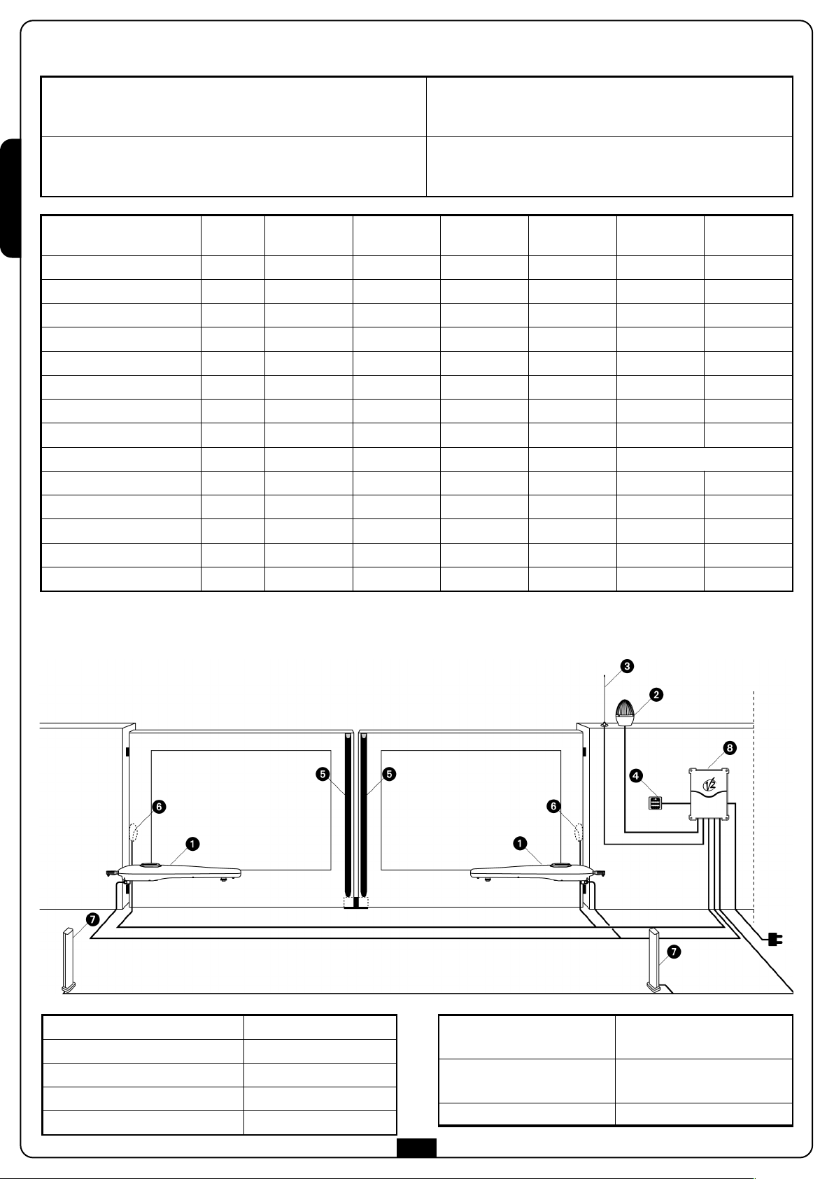
SCHEMA DI INSTALLAZIONE
Attuatore BINGO
Lampeggiante
Antenna
Selettore chiave o digitale
Costa di sicurezza (EN 12978)
cavo 4 x 1 mm
cavo 2 x 1,5 mm
cavo RG-58
cavo 3 x 0,5 mm
-
2
2
Fotocellule interne
Fotocellule esterne
2
Centrale di comando
cavo 4 x 0,5 mm2(RX)
cavo 2 x 0,5 mm2(TX)
cavo 4 x 0,5 mm2(RX)
cavo 2 x 0,5 mm2(TX)
cavo 3 x 1,5 mm
2
2
Page 5
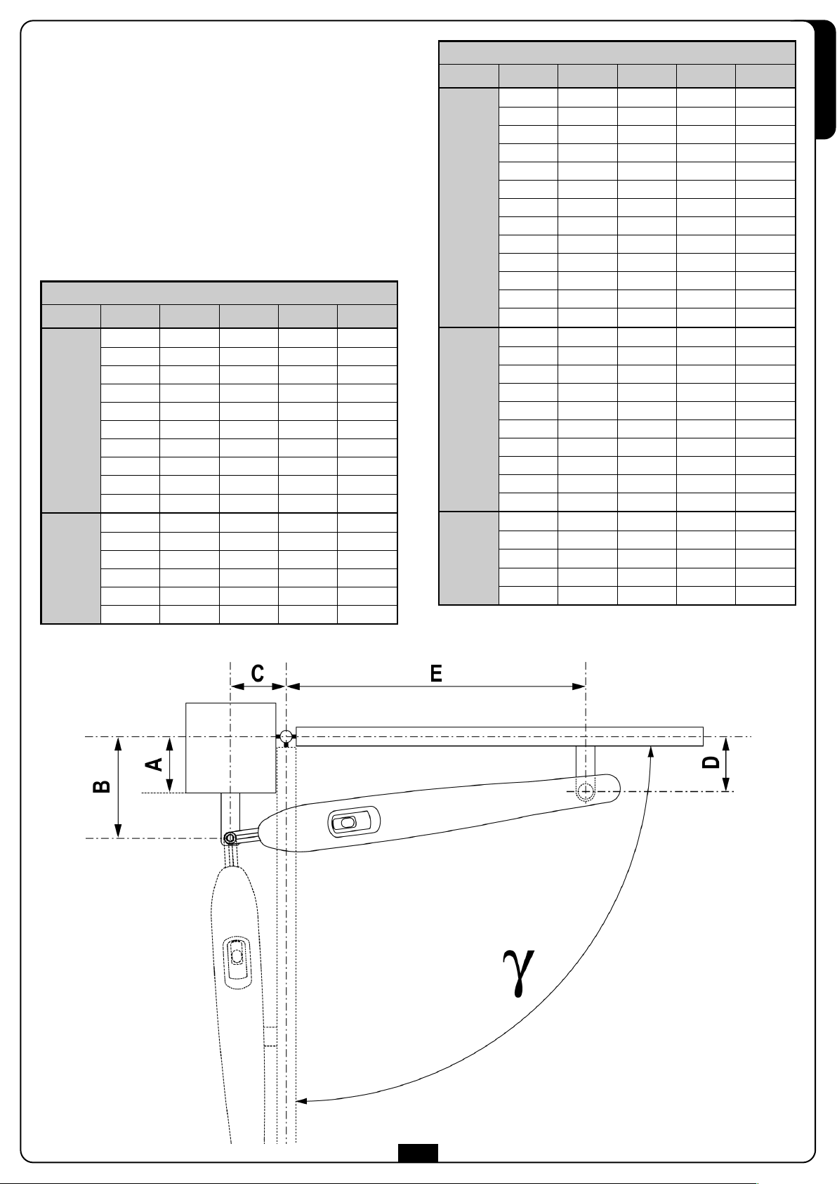
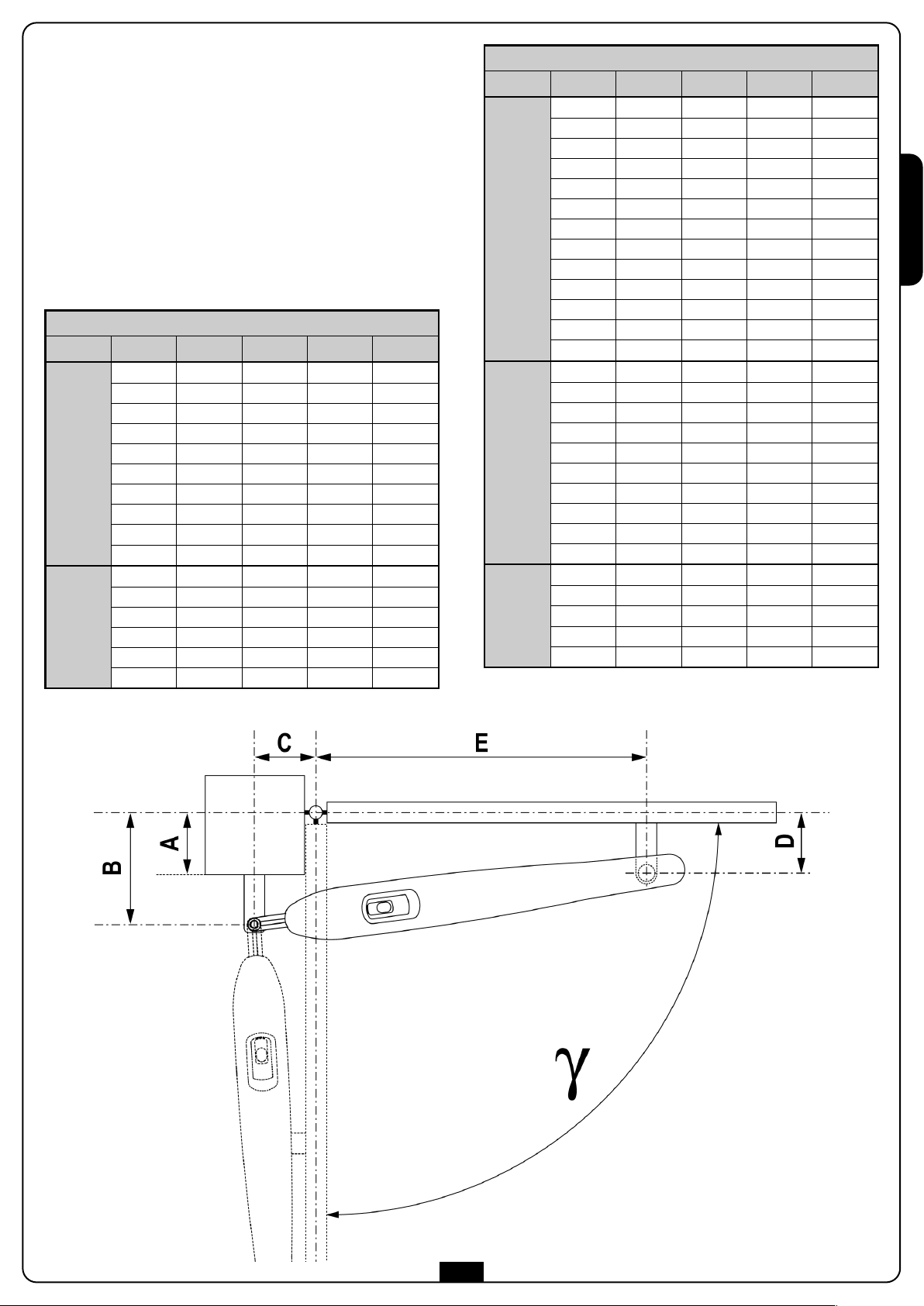
MISURE DI INSTALLAZIONE
Per effettuare una corretta installazione degli operatori e
garantire un funzionamento ottimale dell’automazione è
necessario rispettare le misure riportate in tabella. Eventualmente
modificare la struttura del cancello in modo da adattarlo ad uno
dei casi riportati nella tabella.
m ATTENZIONE: Nel caso in cui l'anta superi i 2,5m di
unghezza è necessario installare una elettroserratura per
l
garantire un'efficace chiusura.
m ATTENZIONE: Al fine di evitare contatti dell’operatore
con l’anta, è necessario rispettare il più precisamente
possibile la quota D considerando una tolleranza compresa
tra 0 e +5 mm.
BINGO400
A [mm] B [mm] C [mm] D [mm] E [mm]
γ
20 140 130 120 695
30 150 160 140 665
40 160 160 140 665
50 170 160 140 665
90°
100°
60 180 150 140 675
70 190 150 120 675
80 200 140 120 685
90 210 130 120 690
100 220 125 120 695
110 210 130 120 690
20 140 165 120 660
30 150 160 120 660
40 140 160 120 660
50 150 160 120 660
60 160 155 120 660
70 160 145 110 670
γ
90°
100°
110°
BINGO500
ITALIANO
A [mm] B [mm] C [mm] D [mm] E [mm]
40 160 150 140 795
50 170 150 140 795
60 180 160 140 785
70 190 160 140 785
80 200 160 140 785
90 210 160 140 785
100 220 160 140 785
110 230 160 140 780
120 240 160 140 780
130 250 160 140 780
140 260 160 140 780
150 270 150 140 790
160 280 150 140 785
40 160 190 140 755
50 170 190 140 755
60 180 190 140 755
70 190 190 140 755
80 200 190 140 755
90 210 190 140 755
100 220 190 140 755
110 230 185 140 760
120 220 190 140 750
130 230 185 140 755
40 160 220 140 725
50 170 220 140 725
60 180 220 140 725
70 170 210 130 730
80 180 205 130 735
3
Page 6

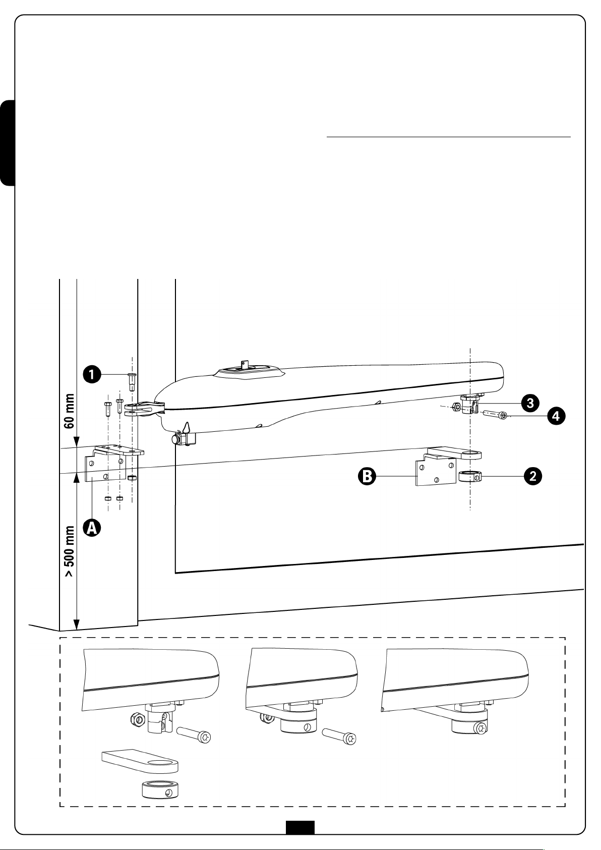
FISSAGGIO DEGLI ATTUATORI
opo aver riportato sui pilastri le misure scelte nella tabella della
D
pagina precedente, procedere con le seguenti operazioni:
ITALIANO
• Fissare le staffe sui pilastri e sul cancello
• Chiudere l'anta
• Sbloccare gli attuatori
m ATTENZIONE: Se si cercasse di inserire la ghiera 2 nel
verso opposto si incontrerebbe una notevole difficoltà nel
montaggio, dovuta alla conicità del foro e della boccola 3.
n condizione di errore un eccessivo forzamento può
I
causare la lesione di alcuni componenti.
• Una volta inserita correttamente la ghiera 2, fissarla sulla
boccola 3 utilizzando la vite 4 con il relativo dado
autobloccante.
• Posizionare il BINGO sulle staffe e fissare il perno 1 con
relativo dado autobloccante come da figura
Inserire la ghiera 2, prestando attenzione al verso con cui va
•
imboccata
• Fare in modo che il foro per il fissaggio della vite 4, sia nella
metà inferiore
• Serrare il dado autobloccante prima di azionare
manualmente le ante.
• Provare più volte ad aprire e chiudere manualmente le ante
controllando che non ci siano attriti tra l'attuatore e la
struttura del cancello.
4
Page 7
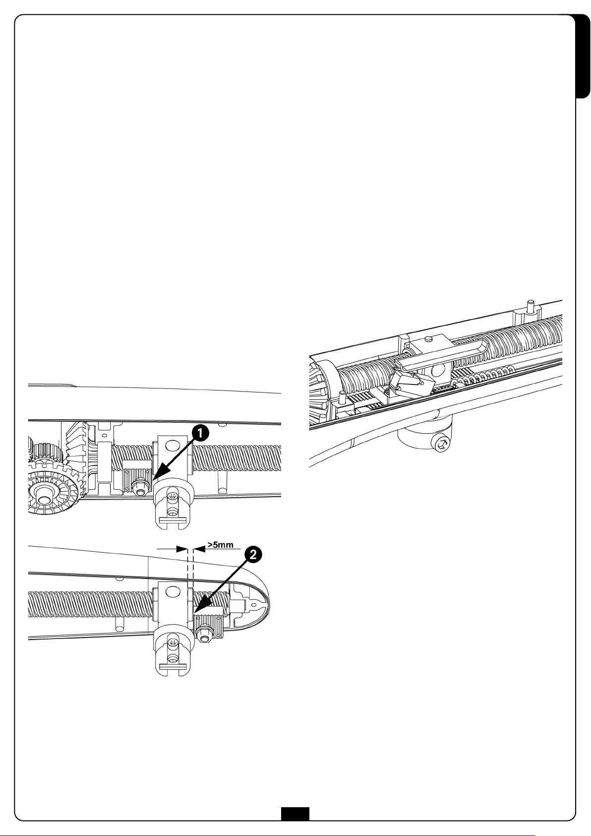
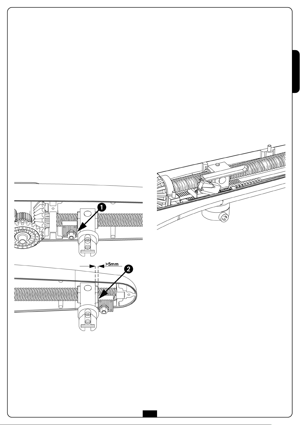
REGOLAZIONE FINECORSA
ITALIANO
Versioni SENZA finecorsa elettrico
Per la regolazione dei finecorsa procedere come segue:
Portare l'anta in posizione di massima apertura, quindi
•
posizionare il fermo meccanico 1 a battuta contro la
chiocciola.
Bloccare il fermo meccanico fissando il bullone con una chiave
•
da 13mm.
• Portare l'anta in posizione di chiusura, quindi posizionare il
ermo meccanico 2 vicino alla chiocciola (mantenere almeno
f
5mm di distanza).
m ATTENZIONE: Il fermo 2 deve essere utilizzato
solamente per le installazioni che non hanno l’arresto di
chiusura, oppure intervenire a causa di un’extracorsa in
condizioni di emergenza.
Evitare di portare il fermo 2 in battuta alla chiocciola in
concomitanza alla chiusura del cancello, dove è presente
l’arresto meccanico dell’anta. Potrebbe nascere un
impuntamento vite chiocciola tale da rendere difficilissimo
lo sblocco del Bingo.
• Bloccare il fermo meccanico fissando il bullone con una chiave
da 13mm.
Versioni CON finecorsa elettrico
Nei modelli equipaggiati con finecorsa elettrico la chiocciola si
ferma 5mm prima dell'arresto meccanico; il finecorsa elettrico
già cablato all’interno del motore) interrompe l'alimentazione sul
(
motore evitando sforzi e surriscaldamenti inutili.
Per la regolazione dei finecorsa procedere come segue:
• Portare l'anta in posizione di massima apertura, quindi
posizionare il fermo meccanico 1 a battuta contro la
chiocciola.
• Bloccare il fermo meccanico fissando il bullone con una chiave
da 13mm.
• Portare l'anta in posizione di massima chiusura, quindi
posizionare il fermo meccanico 2 a battuta contro la
chiocciola.
• Bloccare il fermo meccanico fissando il bullone con
una chiave da 13mm.
5
Page 8
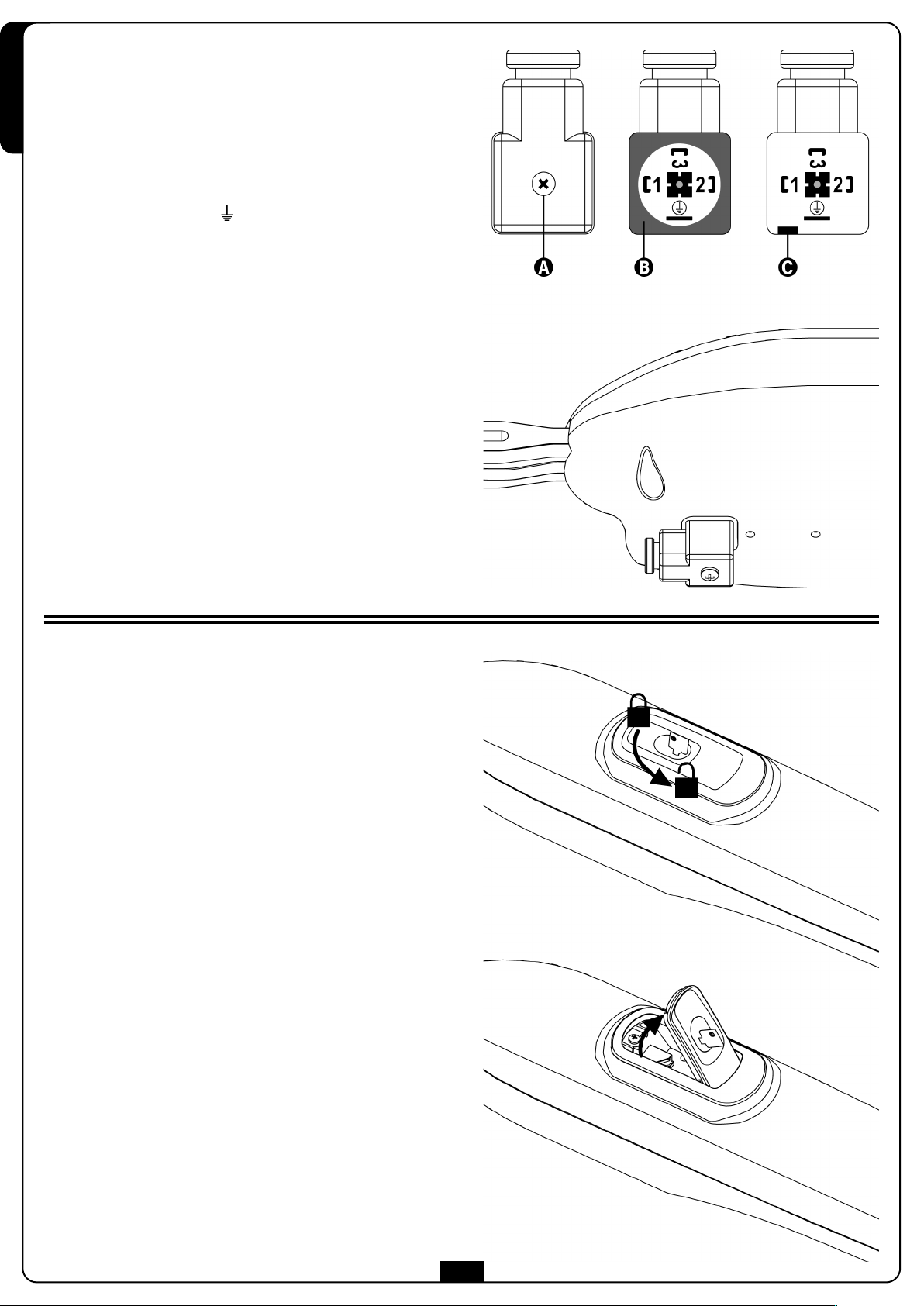
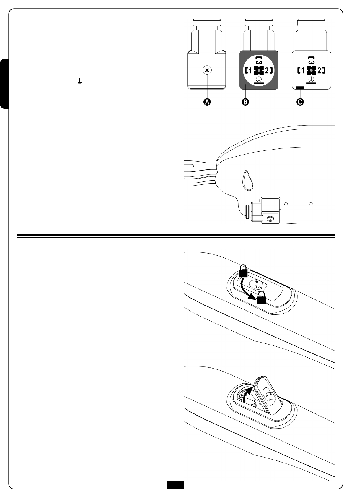
COLLEGAMENTI ELETTRICI
• Svitare la vite A, estrarre il connettore dal motore, togliere
la guarnizione B, quindi aprire il connettore facendo leva
mediante l'utilizzo di un cacciavite nel l'apposita fessura C.
ITALIANO
• Per i BINGO 230V e 120V installati sull'anta destra collegare
i morsetti come segue:
1 cavo di CHIUSURA 3 cavo COMUNE
cavo di APERTURA cavo di TERRA
2
• Per i BINGO 24V collegare i morsetti 1 e 2 del connettore ai
morsetti + e - dell'uscita motori della centrale; collegare
empre il cavo di terra al morsetto.
s
• Per i BINGO installati sull'anta sinistra invertire i cavi sui
morsetti 1 e 2.
• Rimettere la guarnizione B, innestare il connettore, avvitare
la vite A e verificare il corretto funzionamento
dell'automazione.
m ATTENZIONE:
• Collegare sempre il cavo di terra come previsto dalle
normative vigenti (EN 60335-1, EN 60204-1).
• Non utilizzare cavi di diametro superiore a 10 mm.
• In caso di danneggiamento del cavo di alimentazione del
motore, la sostituzione deve essere eseguita da personale
autorizzato.
SBLOCCO DI EMERGENZA
In caso di mancanza di corrente elettrica, il cancello può essere
sbloccato meccanicamente agendo sul motore. Inserire la chiave
in dotazione nella serratura, compiere 1/4 di giro ed aprire
completamente lo sportello in plastica.
Per ripristinare l’automazione è sufficiente richiudere lo sportello,
ruotare nuovamente la chiave in posizione di chiusura e coprire
la serratura per mezzo dell’apposita protezione in plastica a
scorrimento.
6
Page 9
IMPORTANT REMARKS
For any installation problem please contact our Customer Service
at the number +39-0172.812411 operating Monday to Friday
from 8:30 to 12:30 and from 14:00 to 18:00.
For correct installation of the system, we recommend
•
following the instructions issued by UNAC very carefully,
which can be consulted at the following web site:
www.v2home.com
V2 has the right to modify the product without previous
notice; it also declines any responsibility to damage or
injury to people or things caused by improper use or
wrong installation.
m P
before installing and programming your control unit.
• This instruction manual is only for qualified technicians, who
• The contents of this instruction manual do not concern the
• Every programming and/or every maintenance service should
AUTOMATION MUST BE IMPLEMENTED IN COMPLIANCE
WITH THE EUROPEAN REGULATIONS IN FORCE:
EN 60204-1 (Machinery safety electrical equipment of
EN 12445 (Safe use of automated locking devices, test
EN 12453 (Safe use of automated locking devices,
• The installer must provide for a device (es. magnetotermical
• The plastic case has an IP55 insulation; to connect flexible
lease read this instruction manual very carefully
specialize in installations and automations.
end user.
be done only by qualified technicians.
machines, part 1: general rules)
methods)
requirements)
switch) ensuring the omnipolar sectioning of the equipment
from the power supply.
The standards require a separation of the contacts of at
least 3 mm in each pole (EN 60335-1).
or rigid pipes, use pipefittings having the same insulation
level.
DECLARATION OF CONFORMITY
The following statement is applicable only if the below listed
equipments are employed in accordance with the purpose indicated in the instruction manual.
ompany: Contact person:
C
V2 SPA Cosimo De Falco
Corso Principi di Piemonte 65 Chief Executive Officer
12035 RACCONIGI -ITALY
el. +39 01 72 82 10 11
T
Fax +39 01 72 82 10 50
V2 SPA declares that the series of BINGO actuators are in
onformity with the provisions of the following EC directives:
c
73/23/EEC low voltage directive
89/366/CEE electromagnetic compatibility directive
98/37/EEC machine directive
Note: Declares that the above mentioned devices may not be
operated until the machine (automated gate) is identified, CElabeled, and declared to be compliant to the specifications of
Directive 89/392/EEC and following modifications.
The person in charge for the machine start-up must provide the
following records:
• Technical specification paper
• Declaration of conformity
• CE-labeling
• Testing record
• Maintenance record
• Operation manual and directions
ENGLISH
• Installation requires mechanical and electrical skills,
therefore it shall be carried out by qualified personnel only,
who can issue the Compliance Certificate concerning the
whole installation (Machine Directive 98/37/EEC, Annex IIA).
• The automated vehicular gates shall comply with the
following rules: EN 12453, EN 12445, EN 12978 as well as
any local rule in force.
• Also the automation upstream electric system shall comply
with the laws and rules in force and be carried out
workmanlike.
• The door thrust force adjustment shall be measured by
means of a proper tool and adjusted according to the max.
limits, which EN 12453 allows.
• We recommend to make use of an emergency button, to be
installed by the automation (connected to the control unit
STOP input) so that the gate may be immediately stopped
in case of danger.
• The appliance is not to be used by children or persons with
reduced physical, sensory or mental capabilities, or lack of
experience and knowledge, unless they have been given
supervision or instruction.
Racconigi 20/10/2009
V2 SPA legal representative
Cosimo De Falco
PREPARATORY STEPS
The new series of actuadors BINGO, has been devised to serve
gates up to 500 Kg with leaf up to 5 meters wide (look at the
table technical data). Before proceeding with the installation,
please make sure that your gate opens and closes freely, and
that:
• Hinges and pins are in optimum condition and properly
greased.
• No obstacles are within the moving area.
• There is no friction with the ground or between the leaves.
• Your gate is equipped with a central latch.
• Children being supervised do not play with the appliance.
7
Page 10
TECHNICAL DATA
INGO400 - BINGO500 - BINGO400-120V - BINGO500-120V
B
BINGO400-24V - BINGO500-24V
INGO400 02- BINGO500 02
B
Opening and closing mechanical stop
Opening and closing mechanical stop
pening and closing electrical limit switch
O
Built-in trigger capacitor
ENGLISH
BINGO400
BINGO400 02
BINGO400
120V
BINGO500
BINGO500 02
BINGO500
120V
BINGO400
24V
Max. leaf lenght m 3,5 3,5 5 5 3,5 5
Max. leaf weight Kg 400 400 500 500 350 400
Power supply VAC - Hz 230 - 50 120 - 60 230 - 50 120 - 60 24 VDC 24 VDC
Idling current A 2 4 2 4 1,8 1,8
Full load current A 3,2 6 3,2 6 5 5
Maximum Power W 480 480 480 480 120 120
Capacitor µF 8 2 x 10 8 2 x 10 - -
Max travel mm 370 370 490 490 370 490
Operating speed m/s 0,017 0,018 0,017 0,018 0,010 ÷ 0,018
Maximum thrust N 1800 1800 1800 1800 1800 1800
Working temperature °C -30 ÷ +60 -30 ÷ +60 -30 ÷ +60 -30 ÷ +60 -30 ÷ +60 -30 ÷ +60
Protection IP 34 34 34 34 34 34
Working cycle % 30 30 30 30 80 80
Motor weight Kg 11 11 12 12 11 12
INSTALLATION LAYOUT
BINGO500
24V
BINGO actuator
Blinker
Aerial
Key or digital selector
Safety edge (EN 12978)
cable 4 x 1 mm
cable 2 x 1,5 mm
cable RG-58
cable 3 x 0,5 mm
-
2
2
Internal photocells
External photocells
2
Control unit
cable 4 x 0,5 mm2(RX)
cable 2 x 0,5 mm2(TX)
cable 4 x 0,5 mm2(RX)
cable 2 x 1 0,5 mm2(TX)
cable 3 x 1,5 mm
2
8
Page 11
INSTALLATION MEASURES
To carry out a proper installation of the operator parts as well as
to ensure the best automation performance, the measurement
levels shown in the following table shall be complied with.
Change the gate structure to adapt it to one of the cases in the
table, if necessary.
m WARNING: In the case of leaf longer than 2,5 metres,
n electric lock must be fitted to ensure an efficent closig.
a
m WARNING: In order to avoid contatcts of the operator
against the shutter, it is necessary to keep as much exactly
as possible the height D taking into consideration a margin
between 0 and +5mm.
BINGO400
A [mm] B [mm] C [mm] D [mm] E [mm]
γ
20 140 130 120 695
30 150 160 140 665
40 160 160 140 665
50 170 160 140 665
90°
100°
60 180 150 140 675
70 190 150 120 675
80 200 140 120 685
90 210 130 120 690
100 220 125 120 695
110 210 130 120 690
20 140 165 120 660
30 150 160 120 660
40 140 160 120 660
50 150 160 120 660
60 160 155 120 660
70 160 145 110 670
γ
90°
100°
110°
BINGO500
A [mm] B [mm] C [mm] D [mm] E [mm]
40 160 150 140 795
50 170 150 140 795
60 180 160 140 785
70 190 160 140 785
80 200 160 140 785
90 210 160 140 785
100 220 160 140 785
110 230 160 140 780
120 240 160 140 780
130 250 160 140 780
140 260 160 140 780
150 270 150 140 790
160 280 150 140 785
40 160 190 140 755
50 170 190 140 755
60 180 190 140 755
70 190 190 140 755
80 200 190 140 755
90 210 190 140 755
100 220 190 140 755
110 230 185 140 760
120 220 190 140 750
130 230 185 140 755
40 160 220 140 725
50 170 220 140 725
60 180 220 140 725
70 170 210 130 730
80 180 205 130 735
ENGLISH
9
Page 12
ACTUATOR FIXING
hoose measures referring to the table you can find in the
C
previous page, mark them on the pillars and continue as follows:
• Fix brackets on the pillars and on the gate.
m WARNING: inserting the ring nut n. 2 in the opposite
side would be very difficult because of the conicity of the
hole and the bush 3. An over forcing may cause the
damage of some components.
• Close the swing.
• Unlock the actuators.
• Position BINGO on the brackets and fix the pin no. 1 with
ENGLISH
self-locking nut (see the picture).
Insert the ring nut 2, paying attention to the side of the
•
entrance.
• Make that the hole for the fastening of the screw n. 4 is on
the lower side.
• Once inserted correctly the ring nut 2, fix it on the bush
3 using the screw 4 with its self-blocking nut.
• Close the self-blocking nut before hand moving the leaves.
• Try more times to hand open and close the leaves, checking
that there are no frictions between the actuator and the
structure of the gate.
10
Page 13
LIMIT SWITCH ADJUSTMENT
Versions WITHOUT electric limit switch
To adjust the limit switch, please do as follows:
Open the swing as much as possible and position the
•
mechanical stop no. 1 in contact with the female screw.
• Fasten the mechanical stop fixing the bolt using a 13 mm
panner.
s
• Move the leave in closing position, then position the
mechanical stop 2 next to the nut (keep a distance of at least
mm).
5
m PLEASE NOTE: Stop No. 2 must only be used for
installations with no closure stop, or to intervene as a
result of over-running under emergency conditions.
Where the door has a mechanical stop, avoid setting stop
o. 2 at the female screw end-stop when the gate is
N
closing. The female screw could seize in such a way as to
make it very difficult to release the Bingo.
• Fasten the mechanical stop fixing the bolt using a 13 mm
spanner.
Versions WITH electric limit switch
As regards models equipped with electrical limit switches, the
female screw stops 5mm before the mechanical stop; the
lectrical limit switch (already wired inside the motor) interrupts
e
the motor power supply, to avoid unusefull stress and
overheatings.
To adjust the limit switch, please do as follows:
• Open the swing as much as possible and position the
mechanical stop no. 1 in contact with the female screw.
• Fasten the mechanical stop fixing the bolt using a 13 mm
spanner.
• Close the swing as much as possible and position the
mechanical stop no. 2 in contact with the female screw.
• Fasten the mechanical stop fixing the bolt using a 13 mm
spanner.
ENGLISH
11
Page 14
ELECTRICAL CONNECTIONS
• Unscrew “A”, pull the connector out of the motor, remove
the gasket “B”, open the connector levering with a
screwdriver in the slot “C” provided for this purpose.
• As regards 230 V BINGO and 120 V BINGO installed on the
right swing, please connect the terminals as follows:
1 Closing cable, 3 Common cable
Opening cable, Earth wire
2
ENGLISH
• 24 V BINGO require connection of the connector terminals
no. 1 and no. 2 with the control unit terminals + and –.
emember to connect the earth wire with the terminal.
R
• As regards BINGO installed on the left leaf invert
cables on terminals no. 1 and no. 2.
• Replace the gasket “B”, insert the connector, bolt the screw
“A”, and check the correct functioning of the automation.
m WARNING:
• Always remember to connect the earth according to current
standards (EN 60335-1, EN 60204-1).
• Do not use cables with diameter above 10 mm.
• If the feeder is damaged, a replacement must be effected
from licensed and qualified personnel.
EMERGENCY RELEASE
In case of a blackout, the gate can be operated directly from the
motor. Insert the key supplied in the lock, per--form 1/4 of a turn
and open the plastic door completely.
To restore the automation, simply close the door, rotate the key
in closed position and slide the specially provided plastic cover
onto the lock.
12
Page 15

CONSEILS IMPORTANTS
Pour tout précision technique ou problème d’installation
V2 dispose d’un Service Clients à Votre disposition du lundi au
vendredi de 8:30 à 12:30 et de 14:00 heures à 18:00 heures. au
numéro +39-0172.812411
V2 se réserve le droit d’apporter d’éventuelles
modifications au produit sans préavis; elle décline en outre
toute responsabilité pour tous types de dommages aux
personnes ou aux choses dus à une utilisation imporopre
ou à une mauvaise installation.
m Avant de proceder avec l'installation et la
progarmmation, lire attentivement les notices.
• Ce manuel d'instruction est destiné à des techniciens
qualifiés dans le domain des automatismes.
• Aucune des informations contenues dans ce livret pourra
être utile pour le particulier.
• Tous operations de maintenance ou programation doivent
être faites à travers de techniciens qualifiés.
L’AUTOMATION DOIT ÊTRE RÉALISÉE CONFORMÉMENT AUX
DISPOSITIFS NORMATIFS EUROPÉENS EN VIGUEUR:
EN 60204-1 (Sécutité de la machinerie. Équipement
électriquedes machines, partie 1: régles générales).
EN 12445 (Sécutité dans lìutilisation de fermetures
automatisées, méthodes d'essai).
EN 12453 (Sécurité dans l'utilisation de fermetures
automatisées, conditions requises).
• L'installateur doit pourvoir à l'installation d'un dispositif
(ex. interrupteur magnétothermique) qui assure la coupure
omnipolaire de l'équipement du réseau d'alimentation.
La norme requiert une séparation des contacts d'au moins
3 mm pour chaque pôle (EN 60335-1).
• L'enveloppe en plastique de la carte possède une
protection IP55, pour la connexion de tubes rigides ou
flexibles utiliser des raccordements possédant le même
niveau de protection.
Veillez à ce que les enfants ne puissent jouer avec
•
l'appareillage.
• Pour une correcte mise en service du système nous
conseillons de suivre attentivement les indications fournies
par l'association UNAC trouvables dans le site web suivant :
www.v2home.com
DECLARATION DE CONFORMITÉ
La déclaration suivante s’applique seulement si les articles ci-après
ont utilisés dans le but indiqué dans le manuel d’utilisation.
s
Société : Personne à contacter :
V2 SPA Cosimo De Falco
orso Principi di Piemonte 65 Le représentant légal
C
12035 RACCONIGI -ITALY
Tel. +39 01 72 82 10 11
Fax +39 01 72 82 10 50
V2 SPA déclare que les opérateurs de la série BINGO sont
conformes aux qualités requises par les Directives:
2006/95/CEE Directive Basse tension
89/366/CEE Directive compatibilité electromagnétique
98/37/EEC Directive machines
Nota: Déclare que n’est pas permis mettre en service les
dispositifs indiqués ci-dessous jusqu’à quand la
machine (portail automatisé) soie été identifiée, marqué CE et on
aie émise la conformité aux conditions de la Directive 89/392/EEC
et ses modifications.
Le responsable de la mise en service doit fournir les papiers
suivants:
• Dossier technique
• Déclaration de conformité
• Marque CE
• Verbal de vérification
• Registre de l’ entretien
• Notices de montages et avertissements
FRANÇAIS
• L’installation requiert des compétences en matière
d’électricité et mécaniques; doit être faite exclusivement par
techniciens qualifiés en mesure de délivrer l’attestation de
conformité pour l’installation (Directive 98/37/EEC, - IIA).
• Il est obligatoire se conformer aux normes suivantes pour
fermetures véhiculaires automatisées: EN 12453,
EN 12445, EN 12978 et à toutes éventuelles prescriptions
nationales.
• Même l’installation électrique ou on branche l’automatisme
doit répondre aux normesen vigueur et être fait à règles de
l’art.
• La régulation de la force de poussée du vantail doit être
mesurée avec outil spécial et réglée selon les valeurs maxi
admis par la norme EN 12453.
• Nous conseillons d’utiliser un poussoir d’urgence à installer
près de l’automatisme (branché à l’entrée STOP de
l’armoire de commande de façon qui soit possible l’arrêt
immédiat du portail en cas de danger.
• L'appareillage ne doit pas être utilisé par des enfants ou
des personnes affectés d'handicaps physiques et/ou
psychiques, sans la nécessaire connaissance ou
supervision de la part d'une personne compétente.
Racconigi le 20/10/2009
Le représentant dument habilité V2 SPA
Cosimo De Falco
OPÉRATIONS PRÉLIMINAIRES
Ce nouvelle série des opérateurs électromécaniques BINGO, a été
crée pour automatiser portails à battant jusqu’à 500 Kg de poids
et vantail de 5m selon les models (voir tableau caractéristiques
techniques). Avant de procéder à l'installation il est fondamental
de s'assurer que votre portail s'ouvre et se referme sans problème
et de vérifier scrupuleusement les points suivants:
• Gonds et tourillons en très bon état et graissés
opportunément.
• Aucune entrave ne doit empêcher le mouvement.
• Aucun frottement contre le sol et entre les vantaux.
• Votre portail doit être équipé d'arrêt centraux (1).
13
Page 16

CARACTERISTIQUES TECHNIQUES
INGO400 - BINGO500 - BINGO400-120V - BINGO500-120V
B
BINGO400-24V - BINGO500-24V
INGO400 02- BINGO500 02
B
Butée mécanique en ouverture et fermeture
Butée mécanique en ouverture et fermeture
in course électrique en ouverture et fermeture
F
Condensateur de demarrage incorporé
BINGO400
BINGO400 02
BINGO400
120V
BINGO500
BINGO500 02
BINGO500
120V
BINGO400
24V
Longuer maxi du battant m 3,5 3,5 5 5 3,5 5
Poids maxi du battant Kg 400 400 500 500 350 400
Alimentation VAC - Hz 230 - 50 120 - 60 230 - 50 120 - 60 24 VDC 24 VDC
Absorption à vide A 2 4 2 4 1,8 1,8
FRANÇAIS
Absorption maximum A 3,2 6 3,2 6 5 5
Puissance maximum W 480 480 480 480 120 120
Condensateur µF 8 2 x 10 8 2 x 10 - -
Course maxi d'entrainement mm 370 370 490 490 370 490
Vitesse de traction m/s 0,017 0,018 0,017 0,018 0,010 ÷ 0,018
Pousée maximum N 1800 1800 1800 1800 1800 1800
Température de service °C -30 ÷ +60 -30 ÷ +60 -30 ÷ +60 -30 ÷ +60 -30 ÷ +60 -30 ÷ +60
Indìce de protection IP 34 34 34 34 34 34
Cycle de travail % 30 30 30 30 80 80
Poids moteur Kg 11 11 12 12 11 12
SCHÉMA D’INSTALLATION
BINGO500
24V
Actuador BINGO
Clignotant
Antenne radio
Selecteur à clé ou digital
Barre palpeuse de sécurité (EN 12978)
câble 4 x 1 mm
câble 2 x 1,5 mm
câble RG-58
câble 3 x 0,5 mm
-
2
2
Photocellules interne
Photocellules externe
2
Armoire de commande
câble 4 x 0,5 mm2(RX)
câble 2 x 0,5 mm2(TX)
câble 4 x 0,5 mm2(RX)
câble 2 x 0,5 mm2(TX)
câble 3 x 1,5 mm
2
14
Page 17

MESURES D’INSTALLATION
Pour effectuer une bonne installation des actionneurs et garantir
un fonctionnement optimal de l'automatisation il est nécessaire
de respecter leniveaux de mesure reproduits dans le tableau cidessous. Modifier le cas échéant la structure du portail de manière
à l'adapter à l'un des cas de figure énoncés dans le tableau.
m ATTENTION: Les vantaux de plus de 2,50 mètres de
langeur nécessitent l'installation d'une élettroserrure pou
garantir une fermeture efficace.
m ATTENTION: afin d’éviter des contacts entre
l’opérateur et le volet, il se rend nécessaire respecter avec
la plus grande précision la donnée D en considérant une
tolérance comprise entre 0 et +5 mm.
BINGO400
A [mm] B [mm] C [mm] D [mm] E [mm]
γ
20 140 130 120 695
30 150 160 140 665
40 160 160 140 665
50 170 160 140 665
90°
100°
60 180 150 140 675
70 190 150 120 675
80 200 140 120 685
90 210 130 120 690
100 220 125 120 695
110 210 130 120 690
20 140 165 120 660
30 150 160 120 660
40 140 160 120 660
50 150 160 120 660
60 160 155 120 660
70 160 145 110 670
γ
90°
100°
110°
BINGO500
A [mm] B [mm] C [mm] D [mm] E [mm]
40 160 150 140 795
50 170 150 140 795
60 180 160 140 785
70 190 160 140 785
80 200 160 140 785
90 210 160 140 785
100 220 160 140 785
110 230 160 140 780
120 240 160 140 780
130 250 160 140 780
140 260 160 140 780
150 270 150 140 790
160 280 150 140 785
40 160 190 140 755
50 170 190 140 755
60 180 190 140 755
70 190 190 140 755
80 200 190 140 755
90 210 190 140 755
100 220 190 140 755
110 230 185 140 760
120 220 190 140 750
130 230 185 140 755
40 160 220 140 725
50 170 220 140 725
60 180 220 140 725
70 170 210 130 730
80 180 205 130 735
FRANÇAIS
15
Page 18

POUR FIXER LES VERINS
près avoir noté sur les piliers les dimensions souhaitées dans le
A
tableau de la page précédente, procéder avec les opérations
suivantes:
Fixer les pattes sur les piliers et sur le portails.
•
• Fermer le vantail.
Déverrouiller l’opérateur.
•
• Mettre le BINGO sur les pattes et fixer le goujon 1 avec le
autobloquant selon la figure.
• Insérer la frette 2, en faisant attention au sens d'entrée.
• Faire en sorte que le trou pour le fixage de la vis 4 soit
dans la moitié inférieure.
FRANÇAIS
m ATTENTION : Insérer la frette 2 dans le sens contraire
serait très difficile à cause de la conicité du trou et de la
douille 3. En cas d'erreur, forcer excessivement peut
ndommager gravement des composants.
e
• Une fois insérée correctement la frette 2, fixer-la sur la
douille 3 en utilisant la vis 4 avec son dé à blocage
automatique.
• Serrer le dé à blocage automatique avant d'actionner
manuellement les vantaux.
• Essayer plusieurs fois d'ouvrir et fermer manuellement les
vantaux en contrôlant qu'il n' y ait aucune friction entre
l'actuateur et la structure du portail.
16
Page 19

REGULATION FIN COURSE
Version SANS fin de course électrique
Pour régler les fin course mécaniques procéder comme il suive:
Ouvrir le portail au maximum, et après positionner la butée
•
mécanique 1 à feuillure contre l’épaulement du bras.
• Bloquer la butée mécanique en fixant le boulon avec une clé
e 13mm.
d
• Porter le vantail en position de fermeture, donc positionner
l'arrêt mécanique 2 près de la vis creuse 2 (en maintenant au
moins 5 mm de distance).
m ATTENTION: La butée 2 doit être utilisée uniquement
pour les installations qui n'ont pas de butée de fermeture,
ou bien intervenir à cause d'une extracourse en conditions
d'urgence.
Éviter de mener l'arrêt 2 en butée sur l'écrou en
concomitance à la fermeture du portail, où est présent
l'arrêt mécanique de la porte. Un rampage vis limaçon
pourrait avoir lieu: le déblocage du Bingo serait ainsi très
difficile.
• Porter le vantail en position de fermeture, donc positionner
l'arrêt mécanique
Versions AVEC fin de course électrique
Dans les modéls equipès avec fin course éléctrique, l'épaulement
s'arrête 5mm avant de l'arrête mécanique; le fin course
léctrique (déjà câblés dans le moteur) coupe l'alimentation sur
é
le moteur avec le but d'eviter des efforts et surchauffages
inutiles.
Pour régler les fin course mécaniques procéder comme il suive:
• Ouvrir le portail au maximum, et après positionner la butée
mécanique 1 à feuillure contre l’épaulement du bras.
• Bloquer la butée mécanique en fixant le boulon avec une clé
de 13mm.
• Fermer le portail au maximum, et après positionner la butée
mécanique 2 à feuillure contre l’épaulement du bras.
• Bloquer la butée mécanique en fixant le boulon avec une clé
de 13mm.
FRANÇAIS
17
Page 20

CONNEXIONS ÉLECTRIQUES
• Dévisser la vis A, extraire le connecteur de le moteur, enlever
la garniture B, puis ouvrir le connecteur en faisant levier avec
un tournevis dans la fente C.
• Pour BINGO 230V et 120V montés sur le vantail droite
brancher les bornes comme il suive:
1 câble de fermeture 3 câble commune
câble d'ouverture câble de terre.
2
• Pour BINGO 24V brancher les bornes 1 et 2 du connecteur
aux bornes + et – de l’entrée moteur de l’armoire; brancher
oujours le câble de terre au borne.
t
• Sur les BINGO installés sur vantail gauche inverser les
câbles sur les bornières 1 et 2.
• Remettre la garniture B, embrayer le connecteur, visser la vis
A et tester le fonctionnement correct de l’automatisme.
FRANÇAIS
m ATTENTION:
• Brancher imperativement le câble de terre selon les Normes
en vigueur (EN 60335-1, EN 60204-1).
• Ne pas utiliser câbles de diametre supérieur à 10 mm.
• En cas de endommagement du câble d'alimentation du
moteur, le remplacement doit être fait par personnel
autorisé.
MANOEUVRE DE SECOURS
En cas de coupure du courant électrique, le portail peut être
débloqué en agissant sur le moteur. Introduire la clef fournie
dans la serrure qui se trouve sur le côté avant du moteur,
effectuer 1/4 de tour et ouvrir complètement le panneau en
plastique.
Pour re verrouiller le moteur il suffit de refermer le panneau,
tourner à nouveau la clef dans sa position de fermeture et
recouvrir la serrure avec la protection coulissante en plastique
prévue à cet effet.
18
Page 21

ADVERTENCIAS IMPORTANTES
Para cualquier problema técnico ponerse en contacto con el
Servicio Clientes V2 al número +39-0172.812411 activo de lunes
a viernes, desde las 8:30 a las 12:30 y desde las 14:00 a las 18:00.
Si necesitan ser atendidos en CASTELLANO, pueden llamar al
número +34 935809091 de lunes a viernes, desde las 9:00 a las
13:30 y desde las 15:30 a las 19:00.
La V2 se reserva el derecho de aportar eventuales
modificaciones al producto sin previo aviso; ademmás, no
se hace responsable de danos a personas o cosas debidos a
n uso improprio o a una instalación errónea.
u
m Antes de proceder en las installacion y la
programmaciones aconsejable leer bien las instrucciones.
• Dicho manual es destinado exclusivamente a técnicos
calificados en las installacione de automatismos.
• Ninguna de las informacciones contenidas en dicho manual
puede ser de utilidad para el usuario final.
• Cualquiera operacion de manutencion y programacion tendrà
que ser hecha para técnicos calificados en las installacione
de automatismos.
LA AUTOMATIZACION DEBE SER REALIZADA EN
CONFORMIDAD A LAS VIGENTES NORMATIVAS EUROPEAS:
EN 60204-1 (Seguridad de la maquinaria. Equipamiento
electrico de las maquinas, partes 1: reglas
generales).
EN 12445 (Seguridad en el uso de cierres automatizados,
metodos de prueba)
EN 12453 (Seguridad en el uso de cierres automatizados,
requisitos)
• El instalador debe proveer la instalación de un dispositivo
(ej. interruptor magnetotérmico) que asegure el
seccionamiento omnipolar del aparato de la red de
alimentación. La normativa requiere una separación de los
contactos de mínimo 3 mm en cada polo (EN 60335-1).
Para una correcta puesta en servicio del sistema
•
recomendamos seguir cuidadosamente las indicaciones
expedidas por la asociación UNAC disponibles en la
siguiente dirección de Internet: www.v2home.com
DECLARACIONES DE CONFORMIDAD
La siguiente declaración sólo es aplicable si los artículos abajo
enumerados son utilizados para el fin indicado en el manual de
uso.
ociedad: Persona de contacto:
S
V2 SPA Cosimo De Falco
Corso Principi di Piemonte 65 Representante legal
12035 RACCONIGI -ITALY
el. +39 01 72 82 10 11
T
Fax +39 01 72 82 10 50
V2 SPA declara que los actuadores de la serie BINGO son
onformes con los requisitos esenciales fijados por las Directivas:
c
2006/95/CEE Directiva de baja tensión
89/366/CEE Directiva compatibilidad electromagnetica
98/37/EEC Directiva maquinas
Nota: Se declara que no está permitido poner en
marcha los dispositivos que se detallan arriba hasta que la
maquina (puerta automatizada) haya sido identificada, sellada CE
y haya sido emitida la conformidad a las condiciones de la
Directiva 89/392/EEC y posteriores modificaciones.
El responsable de la puesta en funcionamiento tiene que entregar
la siguiente documentación:
• Manual técnico
• Declaración de conformidad
• Sellado CE
• Informe de comprobación final
• Registro de mantenimiento
• Manual de instrucciones y advertencias
ESPAÑOL
• Para la conexión de tubos rígidos o flexibles y pasacables,
utilizar manguitos conformes al grado de protección IP55
como la caja de plástico que contiene la placa.
• La instalación requiere competencias en el campo eléctrico
y mecánico; debe ser realizada únicamente por personal
cualificado en grado de expedir la declaración de
conformidad en la instalación (Directiva máquinas
98/37/EEC, anexo IIA).
• Es obligatorio atenerse a las siguientes normas para cierres
automatizados con paso de vehículos: EN 12453,
EN 12445, EN 12978 y a las eventuales prescripciones
nacionales.
• Incluso la instalación eléctrica antes de la automatización
debe responder a las vigentes normativas y estar realizada
correctamente.
• La regulación de la fuerza de empuje de la hoja debe
medirse con un instrumento adecuado y regulada de
acuerdo con los valores máximos admitidos por la
normativa EN 12453.
• El equipo no debe ser utilizado por infantes o personas con
discapacidades físicas o psíquicas, sin el debido
conocimiento o supervisión por parte de una persona
competente.
Racconigi il 20/10/2009
Rappresentante legale V2 SPA
Cosimo De Falco
OPERACIONES PRELIMINARES
La nueva serie de operadores BINGO ha sido estudiada para
automatizar cancelas batientes pesadas hasta 500 Kg, con
longitud de hoja hasta 5m según las versiones (ver tabla
características técnicas).
Antes de proceder con la instalación, es fundamental asegurarse
de que vuestra cancela abra y cierre libremente y verificar los
siguientes puntos:
• Bisagras y pernios en estado óptimo y oportunamente
lubricados.
• Ningún obstáculo debe impedir el movimiento.
• Ningún roce entre el suelo y las hojas.
• Su cancela ha de estar equipada de topes centrales.
• Vigile a los niños de modo que no jueguen con el equipo.
19
Page 22

DATOS TÉCNICOS
INGO400 - BINGO500 - BINGO400-120V - BINGO500-120V
B
BINGO400-24V - BINGO500-24V
INGO400 02- BINGO500 02
B
Tope mecànico en abertura y cierre
Tope mecànico en abertura y cierre
inal de carrera electrico en apertura y cierre
F
Condensador de arranque incorporado
BINGO400
BINGO400 02
BINGO400
120V
BINGO500
BINGO500 02
BINGO500
120V
BINGO400
24V
Longitud máx. hoja m 3,5 3,5 5 5 3,5 5
Peso máx. hoja Kg 400 400 500 500 350 400
Alimentacion VAC - Hz 230 - 50 120 - 60 230 - 50 120 - 60 24 VDC 24 VDC
Absorcion en vacio A 2 4 2 4 1,8 1,8
Absorcion con carga A 3,2 6 3,2 6 5 5
Potencia maxima W 480 480 480 480 120 120
Condensator µF 8 2 x 10 8 2 x 10 - -
Carrera máx. de arrastre mm 370 370 490 490 370 490
Velocidad de arrastre m/s 0,017 0,018 0,017 0,018 0,010 ÷ 0,018
ESPAÑOL
Empuje max. N 1800 1800 1800 1800 1800 1800
Temperatura de servicio °C -30 ÷ +60 -30 ÷ +60 -30 ÷ +60 -30 ÷ +60 -30 ÷ +60 -30 ÷ +60
Protección IP 34 34 34 34 34 34
Ciclo de trabajo % 30 30 30 30 80 80
Peso operador Kg 11 11 12 12 11 12
ESQUEMA DE INSTALACIÓN
BINGO500
24V
Actuador BINGO
Lámpara de señalización
Antena
Selector a llave o digital
Banda de seguridad (EN 12978)
cable 4 x 1 mm
cable 2 x 1,5 mm
cable RG-58
cable 3 x 0,5 mm
-
2
2
Fotocélulas internas
Fotocélulas externas
2
Cuadro de maniobras
cable 4 x 0,5 mm2(RX)
cable 2 x 0,5 mm2(TX)
cable 4 x 0,5 mm2(RX)
cable 2 x 0,5 mm2(TX)
cable 3 x 1,5 mm
2
20
Page 23

MEDIDAS DE INSTALACION
Para efectuar una correcta instalación de los operadores y
garantizar un funcionamiento óptimo de la automatización, es
necesario respetar las cotas de medición de la tabla.
Eventualmente, modificar la estructura de la puerta, de forma
que se adapte a uno de los casos de la tabla de abajo.
m CUIDADO: En el caso de que la hoja sea superior a
2,5m de longitud es necesario instalar una electrocerradura
para garantizar un cierre eficaz.
UIDADO: a fin de evitar contactos del operador con
m C
la hoja, es necesario respectar más precisamente que
posible la cota D, tenendo en consideración un margen de
tolerancia entre 0 y +5 mm.
BINGO400
A [mm] B [mm] C [mm] D [mm] E [mm]
γ
20 140 130 120 695
30 150 160 140 665
40 160 160 140 665
50 170 160 140 665
90°
100°
60 180 150 140 675
70 190 150 120 675
80 200 140 120 685
90 210 130 120 690
100 220 125 120 695
110 210 130 120 690
20 140 165 120 660
30 150 160 120 660
40 140 160 120 660
50 150 160 120 660
60 160 155 120 660
70 160 145 110 670
γ
90°
100°
110°
BINGO500
A [mm] B [mm] C [mm] D [mm] E [mm]
40 160 150 140 795
50 170 150 140 795
60 180 160 140 785
70 190 160 140 785
80 200 160 140 785
90 210 160 140 785
100 220 160 140 785
110 230 160 140 780
120 240 160 140 780
130 250 160 140 780
140 260 160 140 780
150 270 150 140 790
160 280 150 140 785
40 160 190 140 755
50 170 190 140 755
60 180 190 140 755
70 190 190 140 755
80 200 190 140 755
90 210 190 140 755
100 220 190 140 755
110 230 185 140 760
120 220 190 140 750
130 230 185 140 755
40 160 220 140 725
50 170 220 140 725
60 180 220 140 725
70 170 210 130 730
80 180 205 130 735
ESPAÑOL
21
Page 24

MONTAJE DE LOS OPERADORES
espués de haber trazado en los postes las medidas elegidas en
D
la tabla de la página precedente, proceder con las siguientes
operaciones:
Fijar los soportes a los postes y a las hojas.
•
• Cerrar la hoja.
Desbloquear los operadores.
•
• Colocar el BINGO en los soportes y fijar el pernio 1 con las
tuerca expresa autoblocante, como se puede apreciar en la
igura.
f
• Introducir el anillo 2, con atención al sentido de entrada
• Arreglar de modo que el agujero para el fijado del tornillo 4
esté en la mitad inferior.
m ATENCIÓN: introducir el anillo 2 en el sentido opuesto
es muy dificil, por la forma cónica del agujero y del
casquillo 3. En condición de error, forzar excesivamente
puede dañar componentes.
• Una vez introducido correctamente el anillo 2, fijarlo con el
casquillo 3 utilizando el tornillo 4 con la tuerca expresa
autoblocante.
Apretar la tuerca autoblocante antes de accionar
•
manualmente las hojas.
• Intentar varias veces abrir y cerrar manualmente las hojas,
ontrolando que no haya roces entre el operador y la
c
estructura de la cancela.
ESPAÑOL
22
Page 25

REGULACION FINALES DE CARRERA
Modelo SIN final de carrera eléctrico
Para la regulación de los finales de carrera mecánicos proceder
de la siguiente forma:
• Colocar la hoja en posición de máxima apertura y posicionar
el tope mecánico 1 contra la leva de arrastre.
Bloquear el tope mecánico fijando el tornillo con una llave de
•
13mm.
• Colocar la hoja en posición de cierre y posicionar el tope
ecánico 2 cerca del casquillo del sin fin (manteniendo una
m
distancia de 5 mm).
m ATENCIÓN: El seguro 2 debe ser utilizado solamente
en las instalaciones que no tienen la parada de cierre, o
bien intervenir a causa de una carrera extra en condiciones
de emergencia. Evitar poner el seguro 2 en tope de tornillo
hembra en concomitancia con el cierre de la cancela, donde
se encuentra la parada mecánica del postigo. Podría
producirse un frotamiento del tornillo hembra tal que
pudiera hacer dificilísimo el desbloqueo del Bingo.
• Bloquear el tope mecánico fijando el tornillo con una llave de
13mm.
Modelo CON final de carrera eléctrico
En los modelos equipados con el final de carrera eléctrico la leva
de arrastre se para 5mm antes del tope mecànico; el final de
arrera eléctrico (ya cableados en el motor) corta l'alimentaciòn
c
sobre el motor con la finalidad de evitar esfuerzos y
sobrecalefaciòn inùtil.
Para la regulación de los finales de carrera mecánicos proceder
de la siguiente forma:
• Colocar la hoja en posición de máxima apertura y posicionar
el tope mecánico 1 contra la leva de arrastre.
• Bloquear el tope mecánico fijando el tornillo con una llave de
13mm.
• Colocar la hoja en posición de máxima cierre y posicionar el
tope mecánico 2 contra la leva de arrastre.
• Bloquear el tope mecánico fijando el tornillo con una
llave de 13mm.
ESPAÑOL
23
Page 26

CONEXIONES ELÉCTRICAS
• Aflojar el tornillo A, extraer el conector del motor, quitar la
junta B y abrir el conector haciendo palanca utilizando un
destornillador en la ranura expresa C.
• Para los BINGO 230V y 120V instalados en la hoja derecha
conectar los bornes de la siguiente forma:
1 cable de CIERRE 3 cable COMUN
cable de APERTURA cable de tierra
2
• Para los BINGO 24V los bornes 1 y 2 conectarlos a los
bornes + y - de la salida motores del cuadro; empalmar
iempre el cable de tierra al borne.
s
• Para los BINGO instalados en la hoja de la izquierda invertir
los cables entre los bornes 1 y 2.
• Volver a colocar la junta B, insertar el conector, apretar el
tornillo A y verificar el correcto funcionamiento del automatismo.
m ATENCION:
• Conectar siempre el cable de tierra segun las Normativas
vigentes (EN 60335-1, EN 60204-1).
• No utilizar cables de diametro superior a 10 mm.
• En caso de dañarse el cable de alimentación del motor, la
sustitución tiene que ser efectuada por personal autorizado.
ESPAÑOL
DESBLOQUEO DE EMERGENCIA
En caso de falta de corriente eléctrica, la puerta puede ser
desbloqueada interviniendo sobre el motor. Insertar la llave en
dotación en la cerradura presente en el lado frontal del motor,
realizar 1/4 de giro y abrir completamente la ventanilla de
plástico.
Para restablecer la automatización es suficiente cerrar la
ventanilla, rotar nuevamente la llave en posición de cierre y cubrir
la cerradura con la protección expresa de plástico corrediza.
24
Page 27

AVISOS IMPORTANTES
Para esclarecimentos técnicos ou problemas de instalação a V2
dispõe de um serviço de assistência clientes activo em horário de
abertura. TEL. (+39) 01 72 81 24 11
V2 reserva-se o direito de efectuar eventuais alterações ao
produto sem aviso prévio; declina ainda qualquer
responsabilidade pelos danos a pessoas ou coisas
originados por uso impróprio ou instalação errada.
• Se o cabo de alimentação estiver danificado, a sua
substituição deverá ser feita pelo fabricante, pelo seu
serviço de assistência ou, em todo caso, por pessoa com
qualificação similar, de maneira a prevenir qualquer risco.
• Para uma correta colocação em serviço do sistema
recomendamos observar cuidadosamente as indicações
fornecidas pela associação UNAC e disponibilizadas no
seguinte endereço Internet: www.v2home.com
m LER ATENTAMENTE O SEGUINTE MANUAL DE
INSTRUÇÕES ANTES DE PROCEDER À INSTALAÇÃO.
• O presente manual de instruções destina-se exclusivamente
ao pessoal técnico qualificado no sector das instalações de
automações.
• Nenhuma das informações contidas no manual pode ser
interessante o útil ao utilizador final.
Qualquer operação de manutenção ou de programação
•
deve ser realizada exclusivamente por pessoal qualificado.
A AUTOMAÇÃO DEVE SER REALIZADA EM CONFORMIDADE
COM AS NORMAS EUROPEIAS VIGENTES:
EN 60204-1 (Segurança das máquinas, equipamento
eléctrico das máquinas, parte 1: regras gerais).
EN 12445 (Segurança nos cerramentos automatizados,
métodos de teste).
EN 12453 (Segurança no uso de cerramentos
automatizados, requisitos).
• O instalador deve instalar um dispositivo (ex. interruptor
térmico magnético), que assegure o seccionamento de
todos os pólos do sistema da rede de alimentação.
As normas exigem uma separação dos contactos de pelo
menos 3 mm em cada polo (EN 60335-1).
• Para a conexão dos tubos rijos e flexíveis ou passador de
cabos, utilizar junções conformes ao grau de protecção IP55
ou superior.
• A instalação requer competências no sector eléctrico e
mecânico; só deve ser efectuada por pessoal qualificado
habilitado a passar a declaração de conformidade de tipo A
para a instalação completa (Directriz máquinas 98/37/EEC,
apenso IIA).
• É obrigatório respeitar as seguintes normas para
cerramentos veiculares automatizados: EN 12453,
EN 12445, EN 12978 e as eventuais prescrições nacionais.
CONFORMIDADE COM AS NORMAS
A seguinte declaração aplica-se apenas se os artigos abaixo discriminados forem utilizados de acordo com o fim indicado no
anual de instruções.
m
Empresa: Pessoa a contactar:
V2 SPA Cosimo De Falco
orso Principi di Piemonte 65 O representante legal
C
12035 RACCONIGI -ITALY
Tel. +39 01 72 82 10 11
Fax +39 01 72 82 10 50
V2 SPA declara que os actuadores da série BINGO são conformes
aos requisitos essenciais estabelecidos nas seguintes Directivas:
2006/95/CEE Directiva Baixa Tensão
89/366/CEE Directiva compatibilidade electromagnética
98/37/EEC Directiva máquinas
Nota: Declara que não é permitido colocar em serviço os
dispositivos acima listados antes da máquina (portão
automatizado) ser identificada e marcada CE, e antes que seja
emitida a sua declaração de conformidade às condições da
Directriz 89/392/EEC e sucessivas alterações.
O responsável da colocação em serviço deve fornecer os
seguintes documentos:
• Dossiê técnico
• Declaração de conformidade
• Marca CE
• Acta de teste
• Registo da manutenção
• Manual de instruções e avisos
Racconigi aos 20/10/2009
Representante legal V2 SPA
Cosimo De Falco
PORTUGUÊS
• A instalação a montante da automação também deve
respeitar as normas vigentes e ser realizadas conforme as
regras da arte.
• A regulação da força de impulso da folha deve medir-se
com ferramenta própria e ser regulada conforme os valores
máximos admitidos pela norma EN 12453.
• Aconselhamos utilizar um botão de emergência, a ser
instalado nas proximidades da automação, (conectado com
a entrada STOP da placa de comando) de maneira que seja
possível parar imediatamente o portão no caso de perigo.
• A aparelhagem não deve ser utilizada por crianças ou
pessoas com deficiências físicas ou psíquicas sem o devido
conhecimento ou supervisão de pessoa competente.
• Não deixe as crianças brincarem com a aparelhagem.
OPERAÇÕES PRELIMINARES
A nova série de actuadores BINGO foi estudada para automatizar
portões a batente com peso de até 500 Kg, com folhas de até
5 m de comprimento, consoante os modelos (ver tabela
características técnicas). Antes de iniciar a instalação é
fundamental apurar que o portão se abre e fecha livremente e
verificar escrupulosamente os seguintes pontos:
• Dobradiças e pinos em óptimo estado e bem lubrificados.
• Não deve existir nenhum empecilho a impedir o movimento.
• Não deve haver nenhum atrito com o solo e entre as folhas.
• O portão deve ser dotado de paragem central.
25
Page 28

CARACTERÍSTICAS TÉCNICAS
INGO400 - BINGO500 - BINGO400-120V - BINGO500-120V
B
BINGO400-24V - BINGO500-24V
INGO400 02- BINGO500 02
B
Paragem mecânica em abertura e fechadura
Paragem mecânica em abertura e fechadura,
aragem eléctrica em abertura e fechadura,
p
Condensador de arranque incorporado
BINGO400
BINGO400 02
BINGO400
120V
BINGO500
BINGO500 02
BINGO500
120V
BINGO400
24V
Comprimento máximo porta m 3,5 3,5 5 5 3,5 5
Peso máximo porta Kg 400 400 500 500 350 400
Energia Eléctrica VAC - Hz 230 - 50 120 - 60 230 - 50 120 - 60 24 VDC 24 VDC
Absorção a vácuo A 2 4 2 4 1,8 1,8
Absorção máxima A 3,2 6 3,2 6 5 5
Potência motor W 480 480 480 480 120 120
Condensador µF 8 2 x 10 8 2 x 10 - -
Curso máximo de arrastamento mm 370 370 490 490 370 490
Velocidade de arrastamento m/s 0,017 0,018 0,017 0,018 0,010 ÷ 0,018
Impulso máximo N 1800 1800 1800 1800 1800 1800
Température de fonctionnement °C -30 ÷ +60 -30 ÷ +60 -30 ÷ +60 -30 ÷ +60 -30 ÷ +60 -30 ÷ +60
Grau de protecção IP 34 34 34 34 34 34
Ciclo de trabalho % 30 30 30 30 80 80
Peso motor Kg 11 11 12 12 11 12
PORTUGUÊS
ESQUEMA DE INSTALAÇÃO
BINGO500
24V
Actuador BINGO
Intermitência
Antena
Selector de chave o digital
Banda de seguridad (EN 12978)
cabo 4 x 1 mm
cabo 2 x 1,5 mm
cabo RG-58
cabo 3 x 0,5 mm
-
2
2
Células fotoeléctricas
internas
Células fotoeléctricas
2
externas
Quadro eléctrico
cabo 4 x 0,5 mm2(RX)
cabo 2 x 0,5 mm2(TX)
cabo 4 x 0,5 mm2(RX)
cabo 2 x 0,5 mm2(TX)
cabo 3 x 1,5 mm
2
26
Page 29

MEDIDAS DE INSTALAÇÃO
Para efectuar uma correcta instalação dos operadores e garantir
um funcionamento perfeito da automatização, é necessário
respeitar as cotas de medição referidas na tabela abaixo.
Eventualmente, modificar a estrutura do portão de
maneira a adaptá-lo a um dos casos referidos na tabela abaixo.
m ATENÇÃO: No caso em que a folha tenha um
omprimento superior aos 2 m é necessário instalar uma
c
fechadura eléctrica para garantir uma fechadura.
m ATENÇÃO: Para evitar contactos entre o operador e a
folha é necessário respeitar o mais rigorosamente possível
a cota D, considerando uma tolerância entre 0 e +5 mm.
BINGO400
A [mm] B [mm] C [mm] D [mm] E [mm]
γ
20 140 130 120 695
30 150 160 140 665
40 160 160 140 665
50 170 160 140 665
90°
100°
60 180 150 140 675
70 190 150 120 675
80 200 140 120 685
90 210 130 120 690
100 220 125 120 695
110 210 130 120 690
20 140 165 120 660
30 150 160 120 660
40 140 160 120 660
50 150 160 120 660
60 160 155 120 660
70 160 145 110 670
γ
90°
100°
110°
BINGO500
A [mm] B [mm] C [mm] D [mm] E [mm]
40 160 150 140 795
50 170 150 140 795
60 180 160 140 785
70 190 160 140 785
80 200 160 140 785
90 210 160 140 785
100 220 160 140 785
110 230 160 140 780
120 240 160 140 780
130 250 160 140 780
140 260 160 140 780
150 270 150 140 790
160 280 150 140 785
40 160 190 140 755
50 170 190 140 755
60 180 190 140 755
70 190 190 140 755
80 200 190 140 755
90 210 190 140 755
100 220 190 140 755
110 230 185 140 760
120 220 190 140 750
130 230 185 140 755
40 160 220 140 725
50 170 220 140 725
60 180 220 140 725
70 170 210 130 730
80 180 205 130 735
PORTUGUÊS
27
Page 30

FIXAÇÃO DOS MOTORREDUTORES
pós ter traçado nos pilares as medidas escolhidas na tabela da
A
página anterior, proceder da seguinte forma:
• Fixar as placas de fixação nos pilares e no portão.
• Fechar a folha.
• Desbloquear os motorredutores.
• Colocar o BINGO nas placas de fixação e fixar o parafuso 1
com a respectiva porca autoblocante.
Inserir a anilha 2, tendo em atenção o sentido de entrada.
•
• Fazer com que o buraco para a fixação do parafuso 4 esteja
na parte de baixo.
m ATENÇÃO: Inserir a anilha 2 no lado oposto seria
muito difícil devido à forma cónica do buraco e do
casquilho 3. Caso seja exercida uma pressão excessiva,
oderá causar danos nos componentes.
p
• Uma vez inserida correctamente a anilha 2, fixá-la no
casquilho 3 utilizando o parafuso 4 com a porca
autoblocante.
• Apertar a porca autoblocante antes de accionar
manualmente as folhas.
Tentar várias vezes abrir e fechar manualmente as folhas para
•
verificar se não existem fricções entre o motor e a estrutura
do portão.
PORTUGUÊS
28
Page 31

REGULAÇÃO PARAGENS
Versões SEM fim de curso eléctrico
Para a regulação das paragens proceder da seguinte forma:
Colocar a folha na posição de abertura máxima, posicionar
•
então a paragem mecânica 1 a batente contra o caracol.
• Bloquear a paragem mecânica a fixar o parafuso com uma
have de 13 mm.
c
• Colocar a folha em posição de fecho e posicionar a paragem
automática 2 perto do parafuso oco 2 (mantendo uma
istância de pelo menos 5 mm).
d
m ATENÇÃO: O fim de curso 2 deve ser utilizado
somente nos equipamentos que não possuem a paragem
de fechadura, ou então deve entrar em acção se ocorrer
um movimento excessivo em condições de emergência.
vitar de colocar o fim de curso 2 na paragem do parafuso
E
sem fim no mesmo lugar da fechadura do portão, onde se
encontra a paragem mecânica da folha. Poderia surgir um
bloqueio do parafuso sem fim que tornará dificílimo o
desbloqueio do Bingo.
• Bloquear a paragem mecânica a fixar o parafuso com uma
chave de 13 mm.
Versões COM fim de curso eléctrico
Nos modelos equipados com paragem eléctrica o caracol pára 5
mm antes da parada mecânica; a paragem eléctrica (cablagem
ncluída dentro do motor) interrompe a alimentação do motor
i
evitando esforços e superaquecimentos inúteis.
Para a regulação das paragens proceder da seguinte forma:
• Colocar a folha na posição de abertura máxima, posicionar
ntão a paragem mecânica 1 a batente contra o caracol.
e
• Bloquear a paragem mecânica a fixar o parafuso com uma
chave de 13 mm.
• Colocar a folha na posição de fechadura, posicionar então a
paragem mecânica 2 a batente contra o caracol.
• Bloquear a paragem mecânica a fixar o parafuso com uma
chave de 13 mm.
PORTUGUÊS
29
Page 32

LIGAÇÕES ELÉCTRICAS
• Soltar o parafuso A, extrair o conector do motor, retirar a
vedação B, abrir então o conector a utilizar como alavanca
uma chave de fenda na fenda C.
• Para os BINGO 230V e 120V instalados na folha direita ligar
os bornes da seguinte forma:
1 cabo de FECHADURA 3 cabo COMUM
2 cabo de ABERTURA cabo de TERRA
• Para os BINGO 24V ligar os bornes 1 e 2 do conector aos
ornes + e - da saída motores da central; ligar sempre o
b
cabo de terra ao borne.
• Para os BINGO instalados na folha esquerda inverter os
abos nos bornes 1 e 2.
c
• Recolocar a vedação B, inserir o conector, atarraxar o
parafuso A e verificar o correcto funcionamento da
automação.
m ATENÇÃO:
• Ligar sempre o cabo de terra como previsto pelas
normativas vigentes (EN 60335-1, EN 60204-1).
• Não utilizar cabos de diâmetro superior a 10 mm.
• No caso de danos ao cabo de alimentação do motor, a
substituição deve ser efectuada por pessoal autorizado.
PORTUGUÊS
DESBLOQUEIO DE EMERGÊNCIA
No caso de interrupção da corrente eléctrica, o portão pode ser
desbloqueado mecanicamente a actuar no motor. Inserir a chave
fornecida na fechadura, efectuar 1/4 de giro e abrir
completamente a portinhola plástica.
Para rearmar a automação basta fechar a portinhola, girar
novamente a chave na posição de fechadura e cobrir a fechadura
com a protecção plástica de correr própria.
30
Page 33

WICHTIGE HINWEISE
Für tecnische Erläuterungen oder Installtionsprobleme verfügt die
Firma V2 SPA über einen Kundendienst, der zu Bürozeiten unter
der Telefonnummer (+39) 01 72 81 24 11 erreicht werden kann.
Die Firma V2 SPA behält sich das Recht vor, das Produkt
ohne vorherige Ankündigungen abzuändern; die
Übernahme der Haftung für Schäden an Personen oder
Sachen, die auf einen unsachgemäßen Gebrauch oder eine
fehlerhafte Installation zurückzuführen sind, wird
abgelehnt.
Kinder so beaufsichtigen, dass sie nicht mit dem Gerät spielen.
•
• Für eine korrekte Inbetriebnahme des Systems empfehlen wir,
aufmerksam die von der Vereinigung UNAC herausgegebenen
Hinweise zu befolgen, die Sie auf der Webseite
www.v2home.com finden.
KONFORMITÄTSERKLÄRUNG
Folgende Erklärung ist nur anwendbar, wenn die unten
aufgeführten Artikel zu dem im Bedienungshandbuch
ufgeführten Zweck benutzt werden.
a
m Um die Steuerung fehlerfrei zu installieren und
programmieren zu können, lesen Sie bitte diese
edienungsanleitung sehr aufmerksam durch.
B
• Diese Bedienungsanleitung ist nur für Fachtechniker, die auf
Installationen und Automationen von Toren.
• Keine Information dieser Bedienungsanleitung ist für den
ndbenutzer nützlich.
E
• Jede Programmierung und/oder jede Wartung sollte nur von
geschulten Technikern vorgenommen werden.
DIE AUTOMATISIERUNG MUSS IN ÜBEREINSTIMMUNG MIT
DEN GELTENDEN EUROPÄISCHEN NORMEN ERFOLGEN:
EN 60204-1 (Sicherheit der Maschine elektrische
Ausrüstungen von Maschinen, Teil 1: allgemeine
Anforderungen)
EN 12445 (Nutzungssicherheit kraftbetätigter Tore
rüfverfahren)
EN 12453 (Nutzungssicherheit kraftbetätigter Tore
Anforderungen)
• Der Installateur muss eine Vorrichtung (z.B. thermomagn.
Schalter) anbringen, die Trennung aller Pole des Geräts zum
Versorgungsnetz garantiert. Die Norm verlangt eine Trennung
der Kontakte von mindestens 3 mm an jedem Pol (EN 60335-1).
• Für den Anschluss von Rohren und Schläuchen oder
Kabeldurchgängen sind Verbindungen zu verwenden, die dem
Sicherungsgrad IP55 entsprechen.
• Die Installation erfordert Kenntnisse auf den Gebieten der
Elektrik und Mechanik; sie darf ausschließlich von
kompetentem Personal durchgeführt werden, welches
berechtigt ist, eine vollständige Konformitätserklärung vom
Typ A auszustellen (Maschinenrichtlinie 98/37/EEC, Anlage IIA).
Gesellschaft: Kontaktperson:
V2 SPA Cosimo De Falco
orso Principi di Piemonte 65 Gesetzlicher Vertreter
C
12035 RACCONIGI -ITALY
Tel. +39 01 72 82 10 11
Fax +39 01 72 82 10 50
V2 SPA erklärt daß die Antriebe der Serie BINGO den folgenden
Richtlinien entsprechen:
2006/95/CEE Niederspannungsrichtlinie
89/366/CEE EMC-Richtlinie
98/37/EEC Maschinenrichtlinie
Anmerkung: Legt fest, dass die oben aufgeführten Vorrichtungen
erst in Betrieb genommen werden dürfen, nachdem die Anlage
(Automatiktor) identifiziert und CE-gekennzeichnet, bzw. die
Konformität mit den Anforderungen der Richtlinie 89/392/EWG
einschl. nachfolgender Änderungen erklärt wurde.
Der Verantwortliche der Inbetriebnahme muss folgende
Dokumentation vorlegen:
• Technisches Datenheft
• Konformitätserklärung
• CE-Zertifizierung
• Prüfprotokoll
• Wartungsheft
• Benutzerhandbuch und Gebrauchshinweise
Racconigi, den 20/10/2009
Der Rechtsvertreter der V2 SPA
Cosimo De Falco
DEUTSCH
• Für automatisch betriebene Rolltore ist die Einhaltung der
folgenden Normen obligatorisch: EN 12453, EN 12445,
EN 12978 und alle eventuell geltenden, regionalen
Vorschriften.
• Auch die elektrische Anlage der Automatik muss den
geltenden Normen genügen, und fachgerecht installiert
werden.
• Die Schubkraft des Torflügels muss mit Hilfe eines
geeigneten Instruments gemessen, und entsprechend den in
Richtlinie EN 12453 definierten Höchstwerten eingestellt
werden.
• Es wird empfohlen, in der Nähe der Automatik einen NotausSchalter zu installieren (mit Anschluss an en Eingang STOP
der Steuerkarte), so dass bei Gefahr ein unverzügliches
Halten des Tors bewirkt werden kann.
• Das Gerät darf nicht von körperlich oder psychisch
behinderten Kindern oder Personen ohne entsprechende
Kenntnisse oder Aufsicht seitens einer kompetenten Person
betätigt werden.
VORBEREITNDE ARBEITSSCHRITTE
Die neue Serie von Antrieben BINGO ist „geboren“ um Flügeltore
bis 500 Kg und mit Tor-Flügeln bis 5 Meter Länge zu führen.
(Bitte sehen Sie in die Tafel mit den technischen Daten).
Vor der Installation muss sichergestellt werden, dass sich das Tor
hindernisfrei öffnen und schließen lässt, ferner ist es auf
folgendeVoraussetzungen zu prüfen:
• Angeln und Stifte müssen sich in einwandfreiem Zustand
befinden und hinreichend geschmiert sein.
• Kein Hindernis darf die Bewegung beeinträchtigen.
• Es darf keine Reibung zwischen den Torflügeln und dem
Grund bestehen.
• Ihr Tor muss mit zentralem Feststeller ausgerüstet sein.
31
Page 34

TECHNISCHE DATEN
INGO400 - BINGO500 - BINGO400-120V - BINGO500-120V
B
BINGO400-24V - BINGO500-24V
INGO400 02- BINGO500 02
B
Mechanischer Feststeller für beide Öffnung und Schließen
Mechanischer Feststeller für beide Öffnung und Schließen
lektrischer Endschalter für beide Öffnung und Schließen
E
Kondensator ausgestattet
BINGO400
BINGO400 02
BINGO400
120V
BINGO500
BINGO500 02
BINGO500
120V
BINGO400
24V
BINGO500
24V
Max. Torflügelweite m 3,5 3,5 5 5 3,5 5
Max. Torgewicht Kg 400 400 500 500 350 400
Versongung VAC - Hz 230 - 50 120 - 60 230 - 50 120 - 60 24 VDC 24 VDC
Stromaufnahme ohne Belastung A 2 4 2 4 1,8 1,8
Maximale Stromaufnahme A 3,2 6 3,2 6 5 5
Maximale Leistung W 480 480 480 480 120 120
Kondensator µF 8 2 x 10 8 2 x 10 - -
Max. Hub mm 370 370 490 490 370 490
Laufgeschwindigkeit m/s 0,017 0,018 0,017 0,018 0,010 ÷ 0,018
Max. Schub N 1800 1800 1800 1800 1800 1800
Betriebstemperatur °C -30 ÷ +60 -30 ÷ +60 -30 ÷ +60 -30 ÷ +60 -30 ÷ +60 -30 ÷ +60
Schutzart IP 34 34 34 34 34 34
Arbeitszyklus % 30 30 30 30 80 80
Motorgewicht Kg 11 11 12 12 11 12
INSTALLATIONSPLAN
DEUTSCH
Stellantrieben BINGO
Blinkvorrichtung
Antenne
Schlüssel- oder Digitalwähler
Sicherheitskontaktleisten (EN 12978)
Kabel 4 x 1 mm
Kabel 2 x 1,5 mm
Kabel RG-58
Kabel 3 x 0,5 mm
-
2
2
Innenfotozellen
Außenfotozellen
2
Steuerung
Kabel 4 x 0,5 mm2(RX)
Kabel 2 x 0,5 mm2(TX)
Kabel 4 x 0,5 mm2(RX)
Kabel 2 x 0,5 mm2(TX)
Kabel 3 x 1,5 mm
2
32
Page 35

INSTALLATION
Um eine korrekte Installation der Operatoren zu gewährleisten
und ein optimales Funktionieren der Automatik zu garantieren,
müssen die in der untenstehenden Tabelle aufgeführten
Höhenangaben genau beachtet werden. Es könnte sich eventuell
als notwendig erweisen, die Torstruktur zu verändern,
um sie an eine der hier aufgeführten Konstellationen anzupassen.
m ACHTUNG: Ab Flügelmaß von 2,5 Metern muß ein
elektrisches Schloß zur Gewährleistung einer
wirkungsvollen Scließung angebracht werden.
m ACHTUNG: Während der Installation, halten Sie sich
mit größtmöglicher Genauigkeit an die Messung D (man
kann eine Toleranz zwischen 0 und +5 mm zulassen): das ist
nötig, um Berührungen zwischen dem Antrieb Bingo und
dem Flügel zu vermeiden.
BINGO400
A [mm] B [mm] C [mm] D [mm] E [mm]
γ
20 140 130 120 695
30 150 160 140 665
40 160 160 140 665
50 170 160 140 665
90°
100°
60 180 150 140 675
70 190 150 120 675
80 200 140 120 685
90 210 130 120 690
100 220 125 120 695
110 210 130 120 690
20 140 165 120 660
30 150 160 120 660
40 140 160 120 660
50 150 160 120 660
60 160 155 120 660
70 160 145 110 670
γ
90°
100°
110°
BINGO500
A [mm] B [mm] C [mm] D [mm] E [mm]
40 160 150 140 795
50 170 150 140 795
60 180 160 140 785
70 190 160 140 785
80 200 160 140 785
90 210 160 140 785
100 220 160 140 785
110 230 160 140 780
120 240 160 140 780
130 250 160 140 780
140 260 160 140 780
150 270 150 140 790
160 280 150 140 785
40 160 190 140 755
50 170 190 140 755
60 180 190 140 755
70 190 190 140 755
80 200 190 140 755
90 210 190 140 755
100 220 190 140 755
110 230 185 140 760
120 220 190 140 750
130 230 185 140 755
40 160 220 140 725
50 170 220 140 725
60 180 220 140 725
70 170 210 130 730
80 180 205 130 735
DEUTSCH
33
Page 36

BEFESTIGUNG DER ANTRIEBE
ählen Sie die passenden Maße in der Tafel (auf der
W
vorhergehenden Seite) und zeichnen Sie die gewählten Maße auf
den Pfeiler und gehen dann wie folgt weiter:
Befestigen Sie die Stütze auf der Pfeiler und auf dem Tor.
•
• Schließen Sie den Flügel.
Geben Sie die Antriebe frei.
•
m WICHTIG: sollten Sie probieren, den Ring Nr. 2
umgekehrt einzusetzen, werden Sie auf viele
Schwierigkeiten wegen der Kegelförmigkeit des Lochs und
er Büchse Nr. 3 stoßen. Beim Fehler könnte ein
d
übermäßiger Druck mögliche Beschädigungen an den
Komponenten verursachen.
• Nach Einsetzen des Rings Nr. 2, befestigen Sie diesen an
der Buchse Nr. 3 (zur Befestigung benutzen Sie die Schraube
Nr. 4 und die entsprechende selbstsichernde Mutter).
• Positionieren Sie BINGO auf die Stützen und befestigen Sie
den Stift Nr.1 mit dem entsprechenden Sicherungsmutter
bitte sehen Sie die Abbildung).
(
• Schalten Sie den Ring Nr. 2 ein. Geben Sie acht, dass der
Ring in die genaue Richtung gesteckt wird.
• Das Loch zur Befestigung der Schraube Nr. 4 muss in der
Unterhälfte sich befinden.
• Befestigen Sie die selbstsichernde Mutter, bevor die
Flügel manuell zu betätigen.
• Öffnen und schließen Sie mehrmals die Flügel und
kontrollieren Sie, dass es keine Reibung zwischen dem
Antrieb und der Torstruktur besteht.
DEUTSCH
34
Page 37

EINSTELLUNG DER ENDANASCHLÄGE
Versionen OHNE elektrischen Endschalter
m den mechanischen Feststeller zu regulieren, gehen Sie wie
U
folgt vor:
• Öffnen Sie den Flügel maximal, dann positionieren Sie den
echanischen Feststeller Nr. 1 gegen das Mutterschloss.
m
• Klemmen Sie den mechanischen Feststeller mit Hilfe eines
Bolzens mit einem Schlüssel (Messe des Schlüssels: 13 mm).
• Schließen Sie den Flügel, dann positionieren Sie die
mechanische Sperre Nr. 2 neben dem Mutterschloss (halten
Sie mindestens 5 mm Abstand).
m WICHTIG: Die Sperre Nr. 2 tritt mechanisch in Tätigkeit
nur wenn das Tor ausnahmsweise über den Endschalter
geht.
wenn das Tor komplett geschlossen ist, geben Sie acht,
dass das Mutterschloss nicht gegen die Sperre Nr. 2 ist:
sollte das Mutterschloss gegen die Sperre Nr. 2 sein,
könnte die mögliche Reibung zwischen Schraube und
Mutterschloss die Freigabe des Antriebs „Bingo“
erschweren.
• Klemmen Sie den mechanischen Feststeller mit Hilfe eines
Bolzens mit einem Schlüssel (Messe des Schlüssels: 13 mm)
Versionen MIT elektrischem Endschalter
Was die Modelle mit elektrischem Endschalter betrifft, haltet das
Mutterschloss 5 mm vor dem mechanischen Anschlag; der
lektrische Endschalter (schon mit den Motor Kabelverbunden)
e
unterbrecht die Stromversorgung des Motors, um unnütze
Heißlaufen und Beanspruchungen zu vermeiden.
Um den mechanischen Feststeller zu regulieren, gehen Sie wie
folgt vor:
• Öffnen Sie den Flügel maximal, dann positionieren Sie den
mechanischen Feststeller Nr. 1 gegen das Mutterschloss.
• Klemmen Sie den mechanischen Feststeller mit Hilfe eines
Bolzens mit einem Schlüssel (Messe des Schlüssels: 13 mm)
• Schließen Sie den Flügel maximal, dann positionieren Sie den
mechanischen Feststeller Nr. 2 gegen das Mutterschloss.
• Klemmen Sie den mechanischen Feststeller mit Hilfe eines
Bolzens mit einem Schlüssel (Messe des Schlüssels: 13 mm).
DEUTSCH
35
Page 38

LEKTRISCHE VERBINDUNGEN
E
• Lösen Sie die Schraube A, nehmen den Steckverbinder vom
Motor ab und entfernen Sie die Dichtung B. Dann öffnen Sie
en Steckverbinder, bitte benutzen Sie dazu den
d
Schraubendre-her im Schlitz C.
• Was BINGO des rechten Flügels (230V und 120V) betrifft,
verbinden Sie die Klemmen wie folgt:
1 Kabel für Schließung 3 Allgemeines Kabel
2 Kabel für Öffnung Erdungskabel
• Was BINGO 24 V betrifft, verbinden Sie die Klemmen Nr. 1
und Nr. 2 des Steckverbinders an Klemmen + und – des
Ausganges der Steuerung. Verbinden Sie immer das
Erdungskabel mit der Masse-Klemme.
• Was den Kabelanschluß für den linken Flügel des BINGO
betrifft, vertauschen Sie nur die Drähte die an die Klemmen
1 und 2 sollen.
• Stecken Sie die Dichtung B wieder ein und fügen den
Steckverbinder an Dann verschrauben Sie die Schraube A
und prüfen die fehlerfreie Arbeitsweise der Steuerung.
m ACHTUNG:
• Bitte verbinden Sie immer das Erdungskabel, gemäß den
geltenden Bestimmungen (EN 60335-1, EN 60204-1).
• Benutzen Sie keine Kabel, die den Durchmesser höher als
10 mm haben.
• Wenn das Zuleitungskabel beschädigt ist, sollte der
Austausch nur von autorisierten Fachleuten durchgeführt
werden.
ELEKTRISCHE SICHERHEITEN
Im Fall der Unterbrechung der Stromversorgung kann das Tor
über den Motor freigegeben werden. Führen Sie den
mitgelieferten Schlüssel in das Schloss ein, drehen Sie diesen um
90° und öffnen Sie die Kunststoffabdeckung.
DEUTSCH
Um die Betriebsbereitschaft der Automatik wieder herzustellen,
ist es ausreichend, die Abdeckung wieder zu schließen, den
Schlüssel in die Anfangsposition zurück zu drehen und die
Kunststoffkappe wieder über das Schloss zu schieben.
36
Page 39

BELANGRIJKE WAARSCHUWINGEN
Voor technische ophelderingen of installatieproblemen beschikt
V2 SPA over een assistentiedienst voor klanten die actief is tijdens
kantooruren TEL. (+39) 01 72 81 24 11
V2 SPA behoudt zich het recht voor om zonder voorgaande
kennisgeving eventuele wijzigingen aan het product aan te
brengen; het wijst bovendien elke vorm van
aansprakelijkheid af voor persoonlijk letsel of materiële
schade wegens een oneigenlijk gebruik of een foutieve
installatie.
m Lees met aandacht de volgende handleiding
met instructies voordat u tot de installatie overgaat.
• Deze handleiding met instructies is uitsluitend bestemd voor
technisch personeel dat gekwalificeerd is op het gebied van
installaties van automatische systemen.
• In deze handleiding staat geen informatie die interessant of
nuttig kan zijn voor de eindgebruiker.
• Alle werkzaamheden met betrekking tot het onderhoud of de
programmering moet uitsluitend uitgevoerd worden door
gekwalificeerd personeel.
Controleer kinderen zodat zij niet met de apparatuur gaan
•
spelen.
• Voor een correcte indienststelling van het systeem raden wij
aan om de aanwijzingen die door de vereniging UNAC
verstrekt worden, en die beschikbaar zijn op het internet
adres www.v2home.com met aandacht te volgen
OVEREENKOMST MET DE NORMEN
De volgende verklaring is alleen van toepassing indien de hieron-
er genoemde artikel gebruikt worden voor het doel dat in de
d
gebruikshandleiding vermeld wordt.
Vennootschap: Contactpersoon:
2 SPA Cosimo De Falco
V
Corso Principi di Piemonte 65 Rechtsgeldig
12035 RACCONIGI -ITALY vertegenwoordiger
Tel. +39 01 72 82 10 11
Fax +39 01 72 82 10 50
V2 SPA verklaart dat de actuatoren van de serie BINGO voldoen
aan de vereisten die bepaald worden door de volgende
Richtlijnen:
DE AUTOMATISERING DIENT GEREALISEERD TE WORDEN IN
OVEREENSTEMMING MET DE HEERSENDE EUROPESE
NORMEN:
EN 60204-1 (Veiligheid van de machines, de elektrische uitrusting
van de machines, deel 1, algemene regels).
EN 12445 (Veiligheid bij het gebruik van geautomatiseerde
afsluitingen, testmethodes).
EN 12453 (Veiligheid bij het gebruik van geautomatiseerde
afsluitingen, vereisten).
• De installateur moet voor de installatie van een inrichting
zorgen (bv. thermomagnetische schakelaar) die de
afscheiding van alle polen van het systeem van het
voedingsnet verzekert. De norm vereist een scheiding van de
contacten van minstens 3 mm in elke pool (EN 60335-1).
• Voor de verbinding van stijve en buigzame leidingen of
kabeldoorgangen gebruikt u verbindingen die conform zijn
aan beschermingsklasse IP55 of hoger.
• De installatie vereist bekwaamheden op elektrisch en
mechanisch gebied en mag alleen door gekwalificeerd
personeel uitgevoerd worden dat in staat is een verklaring
van overeenkomst van type A af te geven over de volledige
installatie (Machinerichtlijn 98/37/EEG, bijlage IIA).
• Men is verplicht zich aan de volgende normen inzake
geautomatiseerde afsluitingen voor voertuigen te houden:
EN 12453, EN 12445, EN 12978 en eventuele nationale
voorschriften.
• Ook de elektrische installatie vóór de automatisering moet
voldoen aan de heersende normen en uitgevoerd zijn
volgens de regels van het vak.
• De instelling van de duwkracht van het hek moet gemeten
worden met een daarvoor bestemd instrument in afgesteld
worden in overeenstemming met de maximum waarden die
toegelaten worden door de norm EN 12453.
• Het wordt geadviseerd gebruik te maken van een
noodstopknop die geïnstalleerd wordt in de nabijheid van de
automatisering (aangesloten op de STOP-ingang van de
besturingskaart) zodat het mogelijk is het hek onmiddellijk te
stoppen in geval van gevaar.
2006/95/CEE Richtlijn laagspanning
89/366/CEE Richtlijn EMC
98/37/EEG machinerichtlijn
Opmerking: het is niet toegestaan om bovengenoemde
inrichtingen in werking te stellen zolang de machine (het
geautomatiseerde hek) niet geïdentificeerd is, de
CE-markering ontvangen heeft en zolang de verklaring van
overeenkomst met de voorwaarden van Richtlijn 89/392/EEG en
navolgende wijzigingen niet afgegeven is.
Degene die verantwoordelijk is voor de inwerkingstelling moet de
volgende documenten verstrekken:
• Technisch dossier
• Verklaring van overeenkomst
• CE-markering
• Testrapport
• Onderhoudsregister
• Handleiding met instructies en waarschuwingen
Racconigi, 20/10/2009
De rechtsgeldig vertegenwoordiger van V2 SPA
Cosimo De Falco
HANDELINGEN VOORAF
De nieuwe serie actuatoren BINGO is bestudeerd voor de
automatische werking van zware hekdeuren tot 500 kg met
vleugels tot een lengte van 5 m., afhankelijk van de modellen (zie
de tabel met technische kenmerken). Voordat u tot installatie
overgaat, is het van fundamenteel belang dat uw hek vrij open
en dicht gaat en moeten de volgende punten nauwkeurig
gecontroleerd worden:
• Scharnieren en pennen verkeren in uitstekende staat en zijn
naar behoren gesmeerd.
• De beweging wordt door geen enkel obstakel belemmerd.
• Er mag geen enkele wrijving met de bodem en tussen de
hekvleugels geconstateerd worden.
• Uw hek moet uitgerust zijn met de centrale stop.
NEDERLANDS
• De apparatuur mag niet gebruikt worden door kinderen, of
door personen met lichamelijke of geestelijke handicaps,
zonder de benodigde kennis, of zonder toezicht door een
competent persoon.
37
Page 40

TECHNISCHE KENMERKEN
INGO400 - BINGO500 - BINGO400-120V - BINGO500-120V
B
BINGO400-24V - BINGO500-24V
INGO400 02- BINGO500 02
B
Mechanische stop op de opening en de sluiting
Mechanische stop op de opening en de sluiting, elektrische
indschakelaar op de opening en de sluiting,
e
Ingebouwde condensator van het startvermogen
BINGO400
BINGO400 02
BINGO400
120V
BINGO500
BINGO500 02
BINGO500
120V
BINGO400
24V
BINGO500
24V
Max. poortvleugellengte m 3,5 3,5 5 5 3,5 5
Max. poortvleugelgewicht Kg 400 400 500 500 350 400
Voeding VAC - Hz 230 - 50 120 - 60 230 - 50 120 - 60 24 VDC 24 VDC
Absorptie bij Nullast A 2 4 2 4 1,8 1,8
Max. absorptie A 3,2 6 3,2 6 5 5
Motorvermogen W 480 480 480 480 120 120
Condensator µF 8 2 x 10 8 2 x 10 - -
Max. bewegingsbaan mm 370 370 490 490 370 490
Bewegingssnelheid m/s 0,017 0,018 0,017 0,018 0,010 ÷ 0,018
Max. duwkracht N 1800 1800 1800 1800 1800 1800
Werkingstemperatuur °C -30 ÷ +60 -30 ÷ +60 -30 ÷ +60 -30 ÷ +60 -30 ÷ +60 -30 ÷ +60
Beveiligingsgraad IP 34 34 34 34 34 34
Open-sluitcyclus % 30 30 30 30 80 80
Motorgewicht Kg 11 11 12 12 11 12
INSTALLATIESCHEMA
NEDERLANDS
Actuator BINGO
Knipperlicht
Antenne
Keuzeschakelaar met sleutel,
digitaal toetsenbord of nabijheidslezer
Veiligheidslijsten (EN 12978)
kabel 4 x 1 mm
kabel 2 x 1,5 mm
kabel RG-58
kabel 3 x 0,5 mm
-
2
2
Interne fotocellen
Externe fotocellen
2
Stuurcentrale
kabel 4 x 0,5 mm2(RX)
kabel 2 x 0,5 mm2(TX)
kabel 4 x 0,5 mm2(RX)
kabel 2 x 0,5 mm
kabel 3 x 1,5 mm
2
2
(TX)
38
Page 41

INSTALLATIEMATEN
Voor een correcte installatie van de operators en ter garantie
van een optimale werking van het automatisme is het nodig de
meetwaarden te respecteren die in onderstaande tabel worden
weergegeven.
Wijzig zonodig de structuur van het hek zodat deze aangepast
wordt aan één van de in de tabel aangegeven mogelijkheden.
m LET OP: Indien de hekvleugel langer is dan 2 m., is het
nodig een elektrisch slot te installeren die de doeltreffende
sluiting garandeert.
m LET OP: Om te voorkomen dat de operator in
aanraking komt met de hekvleugel, is het nodig om
waarde D zo nauwkeurig mogelijk in acht te nemen,
waarbij rekening gehouden moet worden met een marge
tussen 0 en +5 mm.
BINGO400
A [mm] B [mm] C [mm] D [mm] E [mm]
γ
20 140 130 120 695
30 150 160 140 665
40 160 160 140 665
50 170 160 140 665
90°
100°
60 180 150 140 675
70 190 150 120 675
80 200 140 120 685
90 210 130 120 690
100 220 125 120 695
110 210 130 120 690
20 140 165 120 660
30 150 160 120 660
40 140 160 120 660
50 150 160 120 660
60 160 155 120 660
70 160 145 110 670
γ
90°
100°
110°
BINGO500
A [mm] B [mm] C [mm] D [mm] E [mm]
40 160 150 140 795
50 170 150 140 795
60 180 160 140 785
70 190 160 140 785
80 200 160 140 785
90 210 160 140 785
100 220 160 140 785
110 230 160 140 780
120 240 160 140 780
130 250 160 140 780
140 260 160 140 780
150 270 150 140 790
160 280 150 140 785
40 160 190 140 755
50 170 190 140 755
60 180 190 140 755
70 190 190 140 755
80 200 190 140 755
90 210 190 140 755
100 220 190 140 755
110 230 185 140 760
120 220 190 140 750
130 230 185 140 755
40 160 220 140 725
50 170 220 140 725
60 180 220 140 725
70 170 210 130 730
80 180 205 130 735
39
NEDERLANDS
Page 42

BEVESTIGING VAN DE ACTUATOREN
Nadat men op de kolommen de maten aangegeven heeft die uit de
tabel van de vorige pagina gekozen zijn, dient men als volgt te
handelen:
• Zet de beugels vast op de kolommen en op het hek.
• Sluit de hekvleugel.
• Deblokkeer de actuatoren.
• Breng de BINGO in positie op de beugels en zet pen 1 vast met
de bijbehorende zelfblokkerende moer zoals de afbeelding toont.
• Plaats ringmoer 2 en let op de richting van de plaatsing.
• Zorg ervoor dat het gat voor de bevestiging van schroef 4
zich in de onderste helft bevindt.
m LET OP: indien geprobeerd wordt om ringmoer 2 in de
tegengestelde richting te plaatsen, zal men aanzienlijke
moeilijkheden bij de montage ondervinden wegens de
conische vorm van het gat en van busje 3.
Bij een fout kan overmatig forceren enkele componenten
schade berokkenen.
• Is ringmoer 2 eenmaal correct geplaatst, dan moet deze
vastgezet worden op busje 3 met gebruik van schroef 4 en de
bijbehorende zelfblokkerende moer.
• Span de zelfblokkerende moer alvorens de hekvleugels met de
hand te activeren.
• Probeer meer keren de hekvleugels met de hand te openen en
e sluiten en controleer of er geen wrijving is tussen de
t
actuator en de hekstructuur.
NEDERLANDS
40
Page 43

INSTELLING EINDSCHAKELAARS
Versies ZONDER elektrische eindschakelaar
Handel als volgt voor de instelling van de eindschakelaars:
Zet de hekvleugel in de stand van maximale opening en breng
•
mechanische stop 1 vervolgens in aanslag tegen het wagen.
• Blokkeer de mechanische stop door de bout met een sleutel
an 13 mm vast te zetten.
v
• Zet de hekvleugel in de gesloten stand en breng mechanische
stop 2 vlakbij het wagen in positie (handhaaf een afstand van
minstens 5 mm).
m Aandacht: De mechanische stop 2 mag enkel gebruikt
worden bij installaties waar er geen grondstop is geplaatst
in de gesloten positie. Wanneer de poort in gesloten
positie stop tegen een grondaanslag mag de interne
echanische eindstop 2 niet tegen de loopwagen
m
geplaatst worden. Ofwel eindstop op de grond ofwel
ingebouwde mechanische eindstop. Niet de beiden.
Wanner beide gebruikt worden kan er in de motor een
kracht onstaan tussen de wagen en de eindstop waardoor
het zeer moeilijk wordt om de motor te ontkoppellen.
Indien een externe eindstop is gebruiktmoet de stop 2
ongeveer 5 mm na de wagen geplaatst worden.
• Blokkeer de mechanische stop door de bout met een sleutel
van 13 mm vast te zetten.
Versies MET elektrische eindschakelaar
In de modellen die met een elektrische eindschakelaar uitgerust
zijn, stopt het wagen 5 mm vóór de mechanische stilstand. De
lektrische eindschakelaar (die reeds in de motor bedraad is)
e
onderbreekt de voeding op de motor en vermijd zo onnodige
inspanningen en oververhitting.
Handel als volgt voor de instelling van de eindschakelaars:
• Zet de hekvleugel in de stand van maximale opening en breng
mechanische stop 1 vervolgens in aanslag tegen het wagen.
• Blokkeer de mechanische stop door de bout met een sleutel
van 13 mm vast te zetten.
• Zet de hekvleugel in de stand van maximale sluiting en breng
mechanische stop 2 vervolgens in aanslag tegen het wagen.
• Blokkeer de mechanische stop door de bout met een sleutel
van 13 mm vast te zetten.
41
NEDERLANDS
Page 44

ELEKTRISCHE AANSLUITINGEN
• Draai schroef A los, trek de connector uit de motor, verwijder
pakking B en open vervolgens de connector door met een
schroevendraaier druk uit te oefenen in de daarvoor
bestemde gleuf C.
• Voor BINGO 230V en 120V die op de rechter hekvleugel
geïnstalleerd zijn, sluit u de klemmen als volgt aan:
1 kabel voor SLUITING 3 GEMEENSCH. kabel
2 kabel voor OPENING kabel voor AARDE
• Voor de BINGO 24V sluit u de klemmen 1 en 2 van de
connector aan op de klemmen + en - van de uitgang van de
motoren van de stuurcentrale. Sluit de aardekabel altijd op
e klem aan.
d
• Voor de BINGO die op de linker hekvleugel geïnstalleerd zijn,
verwisselt u de kabels op de klemmen 1 en 2.
• Plaats pakking B terug, steek de connector naar binnen,
draai schroef A vast en controleer de correctheid van de
automatische werking.
m LET OP:
• Sluit de aardekabel altijd aan zoals bepaald wordt door de
heersende wetgeving (EN 60335-1, EN 60204-1).
• Gebruik geen kabels met een diameter die groter is dan
10mm.
• Indien de voedingskabel van de motor beschadigd is, moet de
vervanging worden uitgevoerd door bevoegd personeel.
DEBLOKKERING IN GEVAL VAN NOOD
Indien de elektrische stroom ontbreekt, kan het hek
mechanisch gedeblokkeerd worden door in te grijpen op de
motor. Steek de bijgeleverde sleutel in het slot, draai de sleutel
1/4 slag en open het plastic deurtje volledig.
Om de automatische werking opnieuw te herstellen, is het
voldoende het deurtje te sluiten, de sleutel opnieuw op de
stand van sluiting te draaien en het slot te bedekken met de
daarvoor bestemde plastic schuifbescherming.
NEDERLANDS
42
Page 45

Page 46

Page 47

Page 48

 Loading...