


BCRTMP-1
UT1553 BCRTMP
FEATURES
p Comprehensive MIL-STD-1553 dual-redundant Bus
Controller (BC) and Remote Terminal (RT) functions
p Multiple message processing capability in BC and
RT modes
p Time tagging and message logging in RT mode
p Automatic polling and intermessage delay in
BC mode
p Programmable interrupt scheme and internally
generated interrupt history list
p Remote terminal operations in ASD/ENASD-certified
(SEAFAC)
p Register-oriented architecture to enhance
programmability
p DMA memory interface with 64K addressability
p Eight mode select inputs configure the device for a
wide variety of 1553 protocols: MIL-STD-1553A,
MIL-STD-1553B, McDonnell Douglas A3818,
A5232, A5690, Grumman Aerospace SP-G-151A
p Comprehensive Built-In-Test (BIT) includes:
Continuous on-line wrap-around test, off-line BIT,
special system wrap-around test
p Available in 144-pin pingrid array or 132-lead flatpack
packages
p Standard Microcircuit Drawing 5962-89501 available
- QML Q compliant
16
16
16
CONTROL
DMA/CPU
MESSAGE
RT PROTOCOL
MESSAGE
BC PROTOCOL
HANDLER
INTERRUPT
CONVER-
PARALLEL
SERIAL-TO-
CONVER-
TO-SERIAL
PARALLEL-
MODULE
DECODER
ENCODER/
CHANNEL
DUAL
BUS
TRANSFER
LOGIC
ADDRESS
16
TIMEOUT
TIMRONA
CLOCK &
RESET
12MHz
MASTER
RESET
GENERATOR
ADDRESS
16
1553
HIGH-PRIORITY
RT ADDRESS
STANDARD INTERRUPT
HIGH-PRIORITY
INTERRUPT LOG
CURRENT COMMAND
BUILT-IN-TEST WORD
POLLING COMPARE
CURRENT BC BLOCK/
STATUS
CONTROL
REGISTERS
LIST POINTER
DATA
16
BUILT-
IN-
TEST
16
16
RT TIMER
INTERRUPT STATUS
INTERRUPT ENABLE
SION
SION
&
HANDLER
&
HANDLER
DATA
CHANNEL
B
1553
DATA
CHANNEL
A
LOGIC
HIGH-PRIORITY
STD PRIORITY LEVEL
STD PRIORITY PULSE
DMA ARBITRATION
REGISTER CONTROL
DUAL-PORT MEMORY CONTROL
RT DESCRIPTOR SPACE
ENABLE
BUILT-IN-TEST
START COMMAND
RESET COMMAND
RESET COMMAND
ACTIVITY STATUS/
OPERATIONAL MODE
PROGRAMMABLE STATUS
WRAP-AROUNDTEST
MULTIPLEXER
TIMRONB
Figure 1. BCRTMP BlockDiagram

BCRTMP-2
Table of Contents
1.0 INTRODUCTION. . . . . . . . . . . . . . . . . . . . . . . . . . . . . . . . . . . . . . . . . . . . . . . . . . . . . . . 3
1.1 Features - Remote Terminal (RT) Mode . . . . . . . . . . . . . . . . . . . . . . . . . . . . . . . . . . 3
1.2 Features - Bus Controller (BC) Mode . . . . . . . . . . . . . . . . . . . . . . . . . . . . . . . . . . . . 3
1.3 Features - Multiple Protocol . . . . . . . . . . . . . . . . . . . . . . . . . . . . . . . . . . . . . . . . . . . 4
2.0 PIN IDENTIFICATION AND DESCRIPTION. . . . . . . . . . . . . . . . . . . . . . . . . . . . . . . . 5
3.0 INTERNAL REGISTERS . . . . . . . . . . . . . . . . . . . . . . . . . . . . . . . . . . . . . . . . . . . . . . . . 17
4.0 SYSTEM OVERVIEW. . . . . . . . . . . . . . . . . . . . . . . . . . . . . . . . . . . . . . . . . . . . . . . . . . . 26
5.0 SYSTEM INTERFACE . . . . . . . . . . . . . . . . . . . . . . . . . . . . . . . . . . . . . . . . . . . . . . . . . . 26
5.1 DMA Transfers . . . . . . . . . . . . . . . . . . . . . . . . . . . . . . . . . . . . . . . . . . . . . . . . . . . 26
5.2 Hardware Interface . . . . . . . . . . . . . . . . . . . . . . . . . . . . . . . . . . . . . . . . . . . . . . . . . 26
5.3 CPU Interconnection . . . . . . . . . . . . . . . . . . . . . . . . . . . . . . . . . . . . . . . . . . . . . . . . 26
5.4 RAM Interface. . . . . . . . . . . . . . . . . . . . . . . . . . . . . . . . . . . . . . . . . . . . . . . . . . . . 28
5.5 Legalization Bus . . . . . . . . . . . . . . . . . . . . . . . . . . . . . . . . . . . . . . . . . . . . . . . . . . . 28
5.6 Transmitter/Receiver Interface . . . . . . . . . . . . . . . . . . . . . . . . . . . . . . . . . . . . . . . . 30
6.0 REMOTE TERMINAL ARCHITECTURE . . . . . . . . . . . . . . . . . . . . . . . . . . . . . . . . . 31
6.1 RT Functional Operation. . . . . . . . . . . . . . . . . . . . . . . . . . . . . . . . . . . . . . . . . . . . . 31
6.1.1 RT Subaddress Descriptor Definitions. . . . . . . . . . . . . . . . . . . . . . . . . . . . . 31
6.1.2 Message Status Word . . . . . . . . . . . . . . . . . . . . . . . . . . . . . . . . . . . . . . . . . 33
6.1.3 Mode Code Descriptor Definition . . . . . . . . . . . . . . . . . . . . . . . . . . . . . . . . 34
6.2 RT Error Detection . . . . . . . . . . . . . . . . . . . . . . . . . . . . . . . . . . . . . . . . . . . . . . . . . 35
6.3 RT Operational Sequence . . . . . . . . . . . . . . . . . . . . . . . . . . . . . . . . . . . . . . . . . . . . 35
7.0 BUS CONTROLLER ARCHITECTURE . . . . . . . . . . . . . . . . . . . . . . . . . . . . . . . . . . . 36
7.1 BC Functional Operation. . . . . . . . . . . . . . . . . . . . . . . . . . . . . . . . . . . . . . . . . . . . . 37
7.2 Polling . . . . . . . . . . . . . . . . . . . . . . . . . . . . . . . . . . . . . . . . . . . . . . . . . . . . . . . . . . 39
7.3 BC Error Detection . . . . . . . . . . . . . . . . . . . . . . . . . . . . . . . . . . . . . . . . . . . . . . . . . 39
7.4 BC Operational Sequence . . . . . . . . . . . . . . . . . . . . . . . . . . . . . . . . . . . . . . . . . . . . 40
7.5 BC Operational Example . . . . . . . . . . . . . . . . . . . . . . . . . . . . . . . . . . . . . . . . . . . . . 41
8.0 MULTIPLE PROTOCOL OPTIONS . . . . . . . . . . . . . . . . . . . . . . . . . . . . . . . . . . . . . . . 42
8.1 Operational Modes . . . . . . . . . . . . . . . . . . . . . . . . . . . . . . . . . . . . . . . . . . . . . . . . . 42
8.1.1 Legalization Select (RT) . . . . . . . . . . . . . . . . . . . . . . . . . . . . . . . . . . . . . . . . 42
8.1.2 Broadcast Option Select (BC, RT) . . . . . . . . . . . . . . . . . . . . . . . . . . . . . . . . 42
8.1.3 RT Response Time Select (RT) . . . . . . . . . . . . . . . . . . . . . . . . . . . . . . . . . . . 42
8.1.4 Mode Code Option Select (BC, RT) . . . . . . . . . . . . . . . . . . . . . . . . . . . . . . . 43
8.1.5 Status Word Option Select (RT) . . . . . . . . . . . . . . . . . . . . . . . . . . . . . . . . . . 43
8.1.6 Message Error Technique Select (RT) . . . . . . . . . . . . . . . . . . . . . . . . . . . . . . 43
8.1.7 Mode code with Data Select (BC, RT) . . . . . . . . . . . . . . . . . . . . . . . . . . . . . 43
8.1.8 Remote Terminal Time Out Option Select (BC, RT) . . . . . . . . . . . . . . . . . . 43
8.2 Additional UT1553 BCRTMP Features . . . . . . . . . . . . . . . . . . . . . . . . . . . . . . . . . 43
8.2.1 DOMC Do Mode Code Control Signal (RT) . . . . . . . . . . . . . . . . . . . . . . . . . 43
8.2.2 Continuous Wrap-Around Circuitry (BC, RT) . . . . . . . . . . . . . . . . . . . . . . . 44
8.2.3 Stop Enable (BC, RT) . . . . . . . . . . . . . . . . . . . . . . . . . . . . . . . . . . . . . . . . . . 44
8.2.4 Forced Busy (RT) . . . . . . . . . . . . . . . . . . . . . . . . . . . . . . . . . . . . . . . . . . . . . 44
8.2.5 ACTIVE Signal (RT) . . . . . . . . . . . . . . . . . . . . . . . . . . . . . . . . . . . . . . . . . . . 44
8.2.6 Transmitter Inhibit Signals (BC, RT) . . . . . . . . . . . . . . . . . . . . . . . . . . . . . . 44
8.2.7 Immediate Clear Mode . . . . . . . . . . . . . . . . . . . . . . . . . . . . . . . . . . . . . . . . . 44
8.2.8 Status Word Generation . . . . . . . . . . . . . . . . . . . . . . . . . . . . . . . . . . . . . . . . . 44
9.0 EXCEPTION HANDLING AND INTERRUPT LOGGING . . . . . . . . . . . . . . . . . . . . 46
10.0 MAXIMUM AND RECOMMENDED OPERATING CONDITIONS . . . . . . . . . . . . 50
11.0 DC ELECTRICAL CHARACTERISTICS . . . . . . . . . . . . . . . . . . . . . . . . . . . . . . . . . . 51
12.0 AC ELECTRICAL CHARACTERISTICS . . . . . . . . . . . . . . . . . . . . . . . . . . . . . . . . . . 52
13.0 PACKAGE OUTLINE DRAWINGS . . . . . . . . . . . . . . . . . . . . . . . . . . . . . . . . . . . . . . . 62

BCRTMP-3
1.0 INTRODUCTION
The monolithic CMOS UT1553 BCRTMP provides the
system designer with an intelligent solution to
MIL-STD-1553 multiplexed serial data bus design
problems. The UT1553 BCRTMP is a single-chip device
that implements two of the three defined MIL-STD-1553
functions - Bus Controller and Remote Terminal - and is
flexible enough to conform to many of the MIL-STD-1553
“industry standards” created between and including releases
of MIL-STD-1553A and MIL-STD-1553B. Designed to
reduce host CPU overhead, the BCRTMP’s powerful state
machines automatically execute message transfers, provide
interrupts, and generate status information. The BCRTMP’s
register-based architecture allows it to conform to the many
protocol options regarding status words, mode codes, use
of Broadcast, Message Error, and RT Response Time as
specified in the various “1553 standards.” Multiple registers
offer many programmable functions as well as extensive
information for host use. In the BC mode, the BCRTMP
uses a linked-list message scheme to provide the host with
message chaining capability. The BCRTMP enhances
memory use by supporting variable-size, relocatable data
blocks. In the RT mode, the BCRTMP implements timetagging and message history functions. It also supports
multiple (up to 128) message buffering and variable length
messages to any subaddress.
The UT1553 BCRTMP is an intelligent, versatile, and easy
to implement device -- a powerful asset to system designers.
1.1 Features - Remote Terminal (RT) Mode
Indexing
The BCRTMP is programmable to index or buffer messages
on a subaddress-by-subaddress basis. The BCRTMP, which
can index as many as 128 messages, can also assert an
interrupt when either the selected number of messages is
reached or every time a specified subaddress is accessed.
Variable Space Allocation
The BCRTMP can use as little or as much memory (up to
64K) as needed.
Selectable Data Storage
Address programmability within the BCRTMP provides
flexible data placement and convenient access.
Sequential Data Storage
The BCRTMP stores/retrieves, by subaddress, all messages
in the order in which they are transacted.
Sequential Message Status Information
The BCRTMP provides message validity, time-tag, and
word-count information, and stores it sequentially in a
separate, cross-referenced list.
Illegalizing Mode Codes and Subaddresses
The host can declare mode codes and subaddresses illegal
by setting the appropriate bit(s) in memory.
Programmable Interrupt Selection
The host CPU can select various events to cause an interrupt
with provision for high and standard priority interrupts.
Interrupt History List
The BCRTMP provides an Interrupt History List that
records, in the order of occurrence, the events that caused
the interrupts. The list length is programmable.
1.2 Features - Bus Controller (BC) Mode
Multiple Message Processing
The BCRTMP autonomously processes any number of
messages or lists of messages that may be stored in a 64K
memory space.
Automatic Intermessage Delay
When programmed by the host, the BCRTMP can delay a
host-specified time before executing the next message in
sequence.
Automatic Polling
When polling, the BCRTMP interrogates the remote
terminals and then compares their status word responses to
the contents of the Polling Compare Register. The BCRTMP
can interrupt the host CPU if an erroneous remote terminal
status word response occurs.
Automatic Retry
The BCRTMP can automatically retry a message on busy,
message error, and/or response time-out conditions. The
BCRTMP can retry up to four times on the same or on the
alternate bus.
Programmable Interrupt Selection
The host CPU can select various events to cause an interrupt
with provision for high and standard priority interrupts.
Interrupt History List
The BCRTMP provides an Interrupt History List that
records, in the order of occurrence, the events that caused
the interrupts. The list length is programmable.
Variable Space Allocation
The BCRTMP uses as little or as much memory (up to 64K)
as needed.
Selectable Data Storage
Address programmability within the BCRTMP provides
flexible data placement and convenient access.

BCRTMP-4
1.3 Features - Multiple Protocol
Since the inception of the loosely defined MIL-STD-1553A
in 1973, various “1553 standards” have developed, all with
their own peculiarities. The UT1553 BCRTMP addresses
MIL-STD-1553A, MIL-STD-1553B, McDonnell Douglas
A3818, McDonnell Douglas A5232, McDonnell Douglas
A5690, and Grumman Aerospace SP-G-151A. While the
part was designed with these “standards” specifically in
mind, the BCRTMP’s flexibility permits conformance to
nearly any conceivable “1553-like standard.” The basic
differences among the various “standards” fall into five
categories:
1) Status Word Definition
2) Mode Code Definition
3) Use of Broadcast
4) Message Error Handling
5) Remote Terminal (RT) Response Time
Status Word Definition
The BCRTMP can operate in a mode where the status word
is defined in strict conformance with MIL-STD-1553B, or
it can operate in a more flexible mode. In this flexible status
word mode, the user can program the individual status word
bits using internal registers.
Mode Code Definition
The designer can place the BCRTMP in an operational mode
so that the device performs in strict conformance with the
mode code definitions for MIL-STD-1553B. The designer
may also opt not to automatically execute mode codes,
providing flexibility in mode code definition and
illegalization.
Use of Broadcast
The BCRTMP has a programmable mode option that allows
the user to determine whether to allow broadcast commands
in a system.
Message Error Handling
Some 1553 protocols (e. g., MIL-STD-1553B) consider any
message error reason to discard the entire message and
suppress status word transmission, while others
(e. g., McDonnell Douglas A3818) define the required
activity according to message error severity. The BCRTMP
can be programmed to conform to either requirement.
Remote Terminal (RT) Response Time
The BCRTMP offers two methods of legalization (Bus
Legalization and DMA Legalization), which the designer
selects depending on the required RT response time.

BCRTMP-5
BUSYACK
Figure 2. BCRTMP Functional Pin Description
D0
D4
D5
D6
D7
D8
D9
D10
D11
D12
D13
D14
D15
A0
A1
A2
A3
A4
A5
A6
A7
A8
A9
A10
A11
A12
A13
A14
A15
LGL0
LGL1
LGL2
LGL3
LGL4
LGL5
LGL6
LGL7
LGL8
LGL9
LGL10
RAZ
RAO
RBZ
RBO
TAZ
TAO
TBZ
TBO
RTA0
RTA1
RTA2
RTA3
RTA4
RTPTY
MD7
MD6
MD5
MD4
MD3
MD2
MD1
MD0
MDO6
MDO5
MDO4
MDO3
MDO2
MDO1
MDO0
MCLK
MCLKD2
CLK
VDD
VDD
VDD
VDD
VSS
VSS
VSS
VSS
WRAPEN
WRAPF
ALTWRAP
FBUSY
DMAR
DMAG
DMAGO
DMACK
BURST
TSCTL
BRDCAST
MC
LGLEN
LGLCMD
ERR
DOMC
STDINTL
STDINTP
HPINT
TIMRONA
TIMRONB
COMSTR
SSYSF
BCRTF
CHA/B
TEST
RD
WR
CS
AEN
BCRTSEL
LOCK
EXTOVR
MRST
MEMCSO
MEMCSI
RRD
RWR
DATA
LINES
++
D1
D2
D3
++
++
++
++
ADDRESS
LINES +
MODE
OUTPUTS*
MODE
SELECT
INPUTS**
CLOCK
SIGNALS
POWER
GROUND
WRAP-AROUND
TEST SIGNALS
FORCED BUSY
SIGNALS
DMA
SIGNALS
LEGALIZATION
BUS*
LEGALIZATION
SIGNALS
CONTROL
SIGNALS
STATUS
SIGNALS
TERMINAL
ADDRESS**
BIPHASE IN
BIPHASE OUT
+
+
**
**
**
+
+
* Pin at high impedance when MRST is low.
** Pin internally pulled up.
+ Pin at high impedance when not asserted.
++ Bidirectional pin.
*** Formerly MEMWIN.
( ) Pingrid array pin identification in parentheses.
Flatpack pin numbers not in parentheses.
ACTIVE
2.0 PIN IDENTIFICATION AND DESCRIPTION
24
25
26
27
28
29
30
31
36
37
38
39
40
41
42
43
91
92
93
94
95
96
97
102
103
104
105
106
107
108
109
110
23
22
21
20
19
18
17
16
(N6)
(P6)
(P7)
(N7)
(R6)
(R7)
(P8)
(R8)
(R9)
(R10)
(P9)
(P10)
(N10)
(R11)
(R12)
(R13)
14
13
12
11
10
9
8
58
74
3
132
34
67
100
1
33
66
99
6
5
4
(B10)
(B9)
(C9)
(A10)
(A9)
(B8)
(A8)
(A7)
(A6)
(B7)
(B6)
(C6)
(A5)
(A4)
(A3)
(B4)
(R4)
(P5)
(R3)
(N5)
(P4)
(P3)
(P2)
(N3)
(P1)
(N2)
(L3)
(M2)
(N1)
(M1)
(L1)
(K14)
(E15)
(J1)
(H3)
(N9)
(G13)
(C7)
(J3)
(N8)
(H13)
(C8)
(K2)
(J2)
(K1)
(L13)
(M14)
(K13)
(M15)
53
52
57
56
51
50
55
54
44
45
46
47
48
49
82
83
84
85
86
81
90
128
129
89
59
62
63
61
60
87
15
88
7
69
64
70
71
122
123
127
124
125
126
111
112
113
114
115
116
117
118
119
120
121
72
73
78
75
77
76
79
80
(N14)
(P14)
(L14)
(N15)
(P12)
(N11)
(P13)
(R14)
(N12)
(N13)
(C13)
(B14)
(B13)
(B12)
(C11)
(D13)
(C10)
(G1)
(H2)
(A12)
(J14)***
(J15)
(H14)
(K15)
(J13)
(A13)
(M3)
(B11)
(K3)
(G15)
(H15)
(F15)
(G14)
(D1)
(F3)
(F1)
(F2)
(G2)
(G3)
(C5)
(B3)
(A2)
(C4)
(C3)
(B2)
(C2)
(D2)
(E3)
(C1)
(E2)
(F14)
(F13)
(E13)
(D15)
(D14)
(C15)
(C14)
(B15)
**

BCRTMP-6
A0 24
R13
TTB Bit 0 (LSB) of the Address bus
A1
A2
A3
A4
A5
A6
A7
A8
A9
A10
A11
A12
25
26
27
28
29
30
31
36
37
38
39
R12
R11
N10
P10
P9
R10
R9
R8
P8
R7
R6
TTB
TTB
TTB
Bit 1 of the Address bus
Bit 2 of the Address bus
Bit 3 of the Address bus
Bit 4 of the Address bus
Bit 5 of the Address bus
Bit 6 of the Address bus
Bit 7 of the Address bus
Bit 8 of the Address bus
Bit 9 of the Address bus
Bit 10 of the Address bus
Bit 11 of the Address bus
40
N7
A13
A14
41
42
P7
P6
TTO
TTO
TTO
NAME
PIN NUMBER
F/P PGA
TYPE ACTIVE DESCRIPTION
A15 43
N6
TTO
TTO
TTO
TTO
TTO
TTO
TTO
TTO
TTO
Bit 12 of the Address bus
Bit 13 of the Address bus
Bit 14 of the Address bus
Bit 15 (MSB) of the Address bus
--
--
--
--
--
--
--
--
--
--
--
--
--
--
--
--
Legend for TYPE and ACTIVE fields:
TUI = TTL input (pull-up)
AL = Active low
AH = Active high
ZL = Active low - inactive state is high impedance
TI = TTL input
TO = TTL output
TTO = Three-state TTL output
TTB = Bidirectional
Notes:
1. Address and data buses are in the high-impedance state when idle.
2. Flatpack pin numbers are same as LCC.
ADDRESS BUS

BCRTMP-7
TTB
TTB
TTB
TTB
D0
D1
D2
D3
91 B10
92
93
94
B9
C9
A10
Bit 0 (LSB) of the Data bus
Bit 1 of the Data bus
Bit 2 of the Data bus
Bit 3 of the Data bus
D4
D5
D6
D7
D8
D9
D10
D11
95
96
97
102
103
104
105
106
A9
B8
A8
A7
A6
B7
B6
C6
TTB
TTB
TTB
TTB
TTB
TTB
TTB
TTB
Bit 4 of the Data bus
Bit 5 of the Data bus
Bit 6 of the Data bus
Bit 7 of the Data bus
Bit 8 of the Data bus
Bit 9 of the Data bus
Bit 10 of the Data bus
Bit 11 of the Data bus
--
--
--
--
--
--
--
--
--
--
--
--
--
--
--
--
--
--
NAME TYPE ACTIVE DESCRIPTION
DATA BUS
D12
D13
D14
D15
107
108
109
110
A5
A4
A3
B4
TTB
TTB
TTB
TTB
Bit 12 of the Data bus
Bit 13 of the Data bus
Bit 14 of the Data bus
Bit 15 (MSB) of the Data bus
--
--
--
--
PIN NUMBER
F/P PGA
NAME TYPE ACTIVE DESCRIPTION
RTA0
TERMINAL ADDRESS INPUTS
44 P12 TUI Remote Terminal Address Bit 0 (LSB). The entire
RT address is strobed in at Master Reset. Verify it
by reading the Remote Terminal Address Register.
All the Remote Terminal Address bits are internally
pulled up.
RTA1 45 N11 TUI Remote Terminal Address Bit 1. This is bit 1 of
the Remote Terminal Address.
RTA2 46 P13 TUI Remote Terminal Address Bit 2. This is bit 2 of
the Remote Terminal Address.
RTA3 47 R14 TUI Remote Terminal Address Bit 3. This is bit 3 of
the Remote Terminal Address.
--
--
--
--
RTPTY 49 N13 TUI Remote Terminal (Address) Parity. This is an odd
parity input for the Remote Terminal Address.
RTA4 48 N12 TUI Remote Terminal Address Bit 4. This is bit 4
(MSB) of the Remote Terminal Address.
--
--
PIN NUMBER
F/P PGA

BCRTMP-8
61
62
63
K15
J15
H14
TI
TI
TI
AL
AL
AL
AEN 60 J13 TI AH
BCRTSEL 87 A13 TUI --
LOCK 15
88
M3
B11
TUI
TUI
AH
AL
7 K3 AL
NAME TYPE ACTIVE DESCRIPTION
CONTROL SIGNALS
69
64
G15
H15
TO
TUI
AL
AL
71 G14 TO AL
70 F15 TO AL
TI
Read. The host uses this in conjunction with CS to read an
internal BCRT register.
Write. The host uses this in conjunction with CS to write an
internal BCRTMP register.
BC/RT Select. This selects between either the Bus
Controller or Remote Terminal mode. The BC/RT Mode
Select bit in the Control Register overrides this input if
the LOCK pin is not high. This pin is internally
pulled high.
Lock. When set, this pin prevents internal changes
to the RT address and BC/RT mode select functions as
well as the Operation Mode select (MD7-MD0) functions.
This pin is internally pulled high.
External Override. Use this in multi-redundant
applications. Upon receipt, the BCRTMP aborts all
current activity. EXTOVR should be connected to
COMSTR output of the adjacent BCRTMP when used.
This pin is internally pulled high.
Memory Chip Select Out. This is the regenerated
MEMCSI input for external RAM during the pseudodual-port RAM mode. The BCRTMP also uses it to select
external memory during memory accesses.
RD
WR
CS
EXTOVR
MRST
MEMCSO
MEMCSI
RRD
RWR
Memory Chip Select In. Used in the pseudo-dual-port
RAM mode only, MEMCSI is received from the host and
is propagated through to the MEMCSO. This pin is
internally pulled high.
RAM Read. In the pseudo-dual-port RAM mode, the host
uses this signal in conjunction with MEMCSO to read
from external RAM through the BCRTMP. It is also the
signal the BCRTMP uses to read from memory. It is
asserted following receipt of DMAG. When the BCRTMP
performs multiple reads, this signal is pulsed.
RAM Write. In the pseudo-dual-port RAM mode, the
CPU and BCRTMP use this to write to external RAM.
This signal is asserted following receipt of DMAG. For
multiple writes, this signal is pulsed.
PIN NUMBER
F/P PGA
Chip Select. This selects the BCRTMP when accessing
the BCRTMP’s internal register.
Address Enable. The host CPU uses AEN to indicate to the
BCRTMP that the BCRTMP’s address lines can be asserted;
this is a precautionary signal provided to avoid address bus
crash. If not used, it must be tied high.
Master Reset. This resets all internal state machines,
encoders, decoders, and registers. The minimum pulse
width for a successful Master Reset is 500ns.

BCRTMP-9
82
83
84
C13
B14
B13
TTO
TO
TTO
ZL
AL
ZL
NAME TYPE ACTIVE DESCRIPTION
85
89
90
B12
A12
C10
TO
TO
TO AL
AL
SSYSF
BCRTF
TEST
128
129
59
G1
H2
J14
TI
TO
TO
AH
AH
AL
STATUS SIGNALS
Timer On - Channel A. When low, this pin indicates that
the BCRTMP is transmitting data. This output remains
active until the data transmission is complete or until the
internal fail-safe timer times out (at 660µs), indicating that
the transceiver should be disabled.
86 C11
TO
AL
ACTIVE 81 D13 TO AH Activity on 1553 Bus. When high, this pin indicates
that the BCRTMP has detected a valid command to any
remote terminal address on the bus.
--
Standard Interrupt Level. This is a level interrupt. It is
asserted when one or more events enabled in either the
Standard Interrupt Enable Register, RT Descriptor, or BC
Command Block occur. Resetting the Standard Interrupt
bit in the High-Priority Interrupt Status/Reset Register
clears the interrupt.
STDINTL
STDINTP
Standard Interrupt Pulse. STDINTP pulses when an
interrupt is logged.
HPINT
High Priority Interrupt. The High-Priority Interrupt level
is asserted upon occurance of events enabled in the High
Priority Interrupt Enable Register. The corresponding
bit(s) in the High-Priority Interrupt Status/Reset Register
reset HPINT.
TIMRONA
TIMRONB
Timer On - Channel B. See TIMRONA description.
COMSTR
CHA/B
ChannelA/B. This indicates the active or last active
channel.
TEST. This pin is used as a factory test pin. (Formerly
MEMWIN.)
PIN NUMBER
F/P PGA
(RT) Command Strobe. The BCRTMP asserts this
signal after receiving a valid command. The BCRTMP
deactivates it after servicing the command.
Subsystem Fail. Upon receipt, this signal propagates
directly to the RT 1553 status word and the BCRTMP
Status Register.
BCRT Fail. this indicates a Built-In-Test (BIT) failure.
In the RT mode, the Terminal Flag bit in 1553 status word
is also set.

BCRTMP-10
NAME TYPE ACTIVE DESCRIPTION
BIPHASE INPUTS
RAO 50 P14 TI
Receive Channel A One. This is the Manchester-encoded
true signal input from Channel A of the bus receiver.
RBO 54 N15 TI Receive Channel B One. This is the Manchester-encoded
true signal input from Channel B of the bus receiver.
RAZ
RBZ
51
55
N14
L14
TI
TI
Receive Channel A Zero. This is the Manchester-encoded
complementary signal input from Channel A of the bus
receiver.
Receive Channel B Zero. This is the Manchester-encoded
complementary signal input from Channel B of the bus
receiver.
--
--
--
--
PIN NUMBER
F/P PGA
NAME TYPE ACTIVE DESCRIPTION
TAO 52 M14 TO
TAZ 53 L13 TO
TBO 56 M15 TO
--
--
--
TBZ 57 K13 TO --
BIPHASE OUTPUTS
Transmit Channel A One. This is the Manchesterencoded true output to be connected to the Channel A bus
transmitter input. This signal is idle low.
Transmit Channel A Zero. This is the Manchesterencoded complementary output to be connected to the
Channel A bus transmitter input. This signal is idle low.
Transmit Channel B One. This is the Manchesterencoded true output to be connected to the Channel B bus
transmitter input. This signal is idle low.
Transmit Channel B Zero. This is the Manchesterencoded complementary output to be connected to the
Channel B bus transmitter input. This signal is idle low.
PIN NUMBER
F/P PGA

BCRTMP-11
72 F14 ZL
73
78
75
F13
E13
D15
AL
AL
ZL
TTO
TI
TTO
TO
NAME TYPE ACTIVE DESCRIPTION
DMA SIGNALS
76 C15 TO AL
BURST 77 D14 TO AH
DMA Request. The BCRTMP issues this signal when access
to RAM is required. It goes inactive after receiving a DMAG
signal.
DMAR
DMAG
DMAGO
DMACK
TSCTL
DMA Grant Out. If DMAG is received but not needed, it
passes through to this output.
DMA Acknowledge. The BCRTMP asserts this signal to
confirm receipt of DMAG, it stays low until memory access
is complete.
PIN NUMBER
F/P PGA
DMA Grant. This input to the BCRTMP allows the
BCRMTP to access RAM. It is recognized 45ns before
the rising edge of MCLKD2.
Three-State Control. This signal indicates when the
BCRTMP is actually accessing memory. The host
subsystem’s address and data lines must be in the highimpedance state when the signalis active. This signal assists
in placing the external data and address buffers into the highimpedance state.
Burst (DMA Cycle). This indicates that the current
DMA cycle transfers at least two words; worst-case is five
words plus a “dummy” word.

BCRTMP-12
MODE SELECT INPUTS
NAME
PIN NUMBER
TYPE ACTIVE DESCRIPTION
F/P PGA
MD7 23 R4 TUI --
Mode 7. This input selects between two Remote
Terminal Time Out (RTO) options. When this signal is
high, the selected RTO is 16µs. When this signal is low,
the selected RTO is 32µs.
MD6 22 P5 TUI --
Mode 6. This input selects whether mode codes with
data are allowed in the selected 1553 protocol. When
this signal is high, the protocol does allow mode codes
with data. When this signal is low, the protocol does not
allow mode codes with data.
MD5 21 R3 TUI --
Mode 5. This input selects the message error handling
technique. When this signal is high, the message error
handling technique is as defined in MIL-STD-1553B.
When the signal is low, the message error handling
technique is as defined in MACAIR A3818.
MD4 20 N5 TUI --
Mode 4. This input selects between MIL-STD-1553A
and MIL-STD-1553B status word protocol. When this
signal is high, the selected status word protocol is the
“B” option. When this signal is low, the selected status
word protocol is the “A” option.
MD3 19 P4 TUI --
Mode 3. This input selects between MIL-STD-1553A
and MIL-STD-1553B mode code protocol. When this
signal is high, the selected mode code protocol is the
“B” option. When this signal is low, the selected mode
code protocol is the “A” option.
MD2 18 P3 TUI --
Mode 2. This input selects between MIL-STD-1553A
and MIL-STD-1553B RT Response Time protocol.
When this signal is high, the selected response time
protocol is the “B” option. This signal is low, the
selected response time protocol is the “A” option.
MD1 17 P2 TUI --
Mode 1. This input selects whether broadcast is allowed.
When this signal is high, broadcast is allowed. When
this signal is low, broadcast is not allowed. When MD1
is low, RT address 11111 is treated like RT addresses
00000-11110.
MD0 16 N3 TUI --
Mode 0. This input selects the legalization method.
When this signal is high, the DMA method of
legalization is used. When this signal is low, the
legalization bus is used.

BCRTMP-13
MODE OUTPUTS
NAME
PIN NUMBER
TYPE ACTIVE DESCRIPTION
F/P PGA
MD06 14 P1 TTO --
Mode 6 Out. This output signal reflects the internal
state of Mode 6 (MD6).
MDO5 13 N2 TTO --
Mode 5 Out. This output signal reflects the internal
state of Mode 5 (MD5).
MDO4 12 L3 TTO --
Mode 4 Out. This output signal reflects the internal
state of Mode 4 (MD4).
MDO3 11 M2 TTO --
Mode 3 Out. This output signal reflects the internal
state of Mode 3 (MD3).
MDO2 10 N1 TTO --
Mode 2 Out. This output signal reflects the internal
state of Mode 2 (MD2).
MDO1 9 M1 TTO --
Mode 1 Out. This output signal reflects the internal
state of Mode 1 (MD1).
MD00 8 L1 TTO --
Mode 0 Out. This output signal reflects the internal
state of Mode 0 (MD0).
FORCED BUSY SIGNAL
NAME
PIN NUMBER
TYPE ACTIVE DESCRIPTION
F/P PGA
FBUSY 79 C14 TUI AL
Forced Busy. This signal places the RT in a mode
where it will automatically respond to a command
with the Busy bit set in the RT status word. No DMA
memory bus accesses are necessary, and the memory
buses remain in the high-impedance state until the
busy mode is exited. If the RT is involved in a 1553
message transaction then entry into the busy state is
held off until completion of the last DMS associated
with that message. Upon entry into the busy state, the
BCRTMP asserts the BUSYACK signal.
BUSYACK 80 N2 TTO --
Busy Acknowledge. This signal indicates that the
BCRTMP has entered the Forced Busy state.

BCRTMP-14
WRAP-AROUND TEST SIGNALS
NAME
PIN NUMBER
TYPE ACTIVE DESCRIPTION
F/P PGA
WRAPEN
6 K2 TUI AL
Wrap-Around Enable. When this signal is low, thE
continuous wrap-around feature is enabled.
WRAPF
5 J2 TO AH
Wrap Fail. When high, this pin indicates that the
continuous wrap-around circuitry has detected a
failure.
ALTWRAP
4 K1 TUI AL
Alternate Wrap-Around. This signal, when used in
conjunction with WRAPEN, places the BCRTMP in
a special system diagnostic mode, where the two 1553
buses are connected by a stub, and commands
transmitted over one bus are received through the
continuous wrap circuitry on the other bus. This
permits off-line testing of both channels and the
associated 1553 interface components.
LEGALIZATION BUS
NAME
PIN NUMBER
TYPE ACTIVE DESCRIPTION
F/P PGA
LGL10
121 E2 TTO --
Legalization bus bit 10. The Legalization bus bits 010 reflect bit times 19-9 of the current command (i.e.,
LGL10 = Current Command bit time 9 and LGL0 =
Current Command bit time19. This bus is used to
determine whether or not the command is legal. This
bus can also be used to selectively determine if auto-
execution of a particular mode code is allowed.
LGL9 120 C1 TTO --
Legalization bus bit 9
LGL8 119 E3 TTO --
Legalization bus bit 8
LGL7 118 D2 TTO --
Legalization bus bit 7
LGL6 117 C2 TTO --
Legalization bus bit 6
LGL5 116 B2 TTO --
Legalization bus bit 5
LGL4 115 C3 TTO --
Legalization bus bit 4. When the MACAIR A3818
method of error logging is selected, Legalization bus
bits 4-0 reflect the word count for the defective
data word.
LGL3
114 C4 TTO --
Legalization bus bit 3
LGL2
113 A2 TTO --
Legalization bus bit 2
LGL1
112 B3 TTO --
Legalization bus bit 1
LG10
111 C5 TTO --
Legalization bus bit 0

BCRTMP-15
NAME TYPE ACTIVE DESCRIPTION
CLK
MCLK
MCLKD2
3
58
74
J1
K14
E15
TI
TI
TO
Memory Clock Divided by Two. This signal is the
Memory Clock input divided by two. It assists the
host subsystem in synchronizing DMA events.
Clock. The 12MHz input clock requires a 50%
± 10% duty cycle with an accuracy of ± 0.01%. The
accuracy is required in order to meet the Manchester
encoding/decoding requirements of MIL-STD-1553.
Memory Clock. This is the input clock frequency the
BCRTMP uses for memory accesses. The memory cycle
time is equal to two MCLK cycles. Therefore, RAM
access time is dependent upon the chosen MCLK
frequency (6MHz minimum, 12MHz maximum). Please
see the BCRTMP DMA timing diagrams in this data sheet.
--
--
--
CLOCK SIGNALS
PIN NUMBER
F/P PGA
LEGALIZATION SIGNALS
NAME
PIN NUMBER
TYPE ACTIVE DESCRIPTION
F/P PGA
BRDCAST
122 D‘ TTO AH
Broadcast. When high, this pin indicates that the
current command is a broadcast command.
MC
123 F3 TTO AH
Mode Code. When high, this pin indicates that the
current command is a mode command.
LGLEN
127 F1 TTO AL
Legalization Bus Enable. When low, this pin enables
the user-supplied legalization logic (if the
Legalization bus is used).
LGLCMD 124 F2 TUI AH
Legal Command. A high on this input signal indicates
to the BCRTMP that the current command is legal.
ERR 125 G2 TO AL
Error. When low, this pin indicates that a data word
parity error or a Manchester error occurred in the
current command. When this signal is asserted, the
Legalization bus bits 4-0 contain the word count for
the defective data word.
DOMC 126 G3 TUI AH
Do Mode Code. When high, this signal enables the
automatic execution of mode codes. When low, this
signal disables auto-execution.

BCRTMP-16
NAME TYPE ACTIVE DESCRIPTION
132
34
67
100
1
33
66
99
H3
N9
G13
C7
J3
N8
H13
C8
PWR
PWR
PWR
PWR
GND
GND
GND
GND
+5V
+5V
+5V
+5V
Ground
Ground
Ground
Ground
--
--
--
--
--
--
--
--
POWER AND
V
DD
V
SS
V
DD
V
DD
V
DD
V
SS
V
SS
V
SS
PIN NUMBER
F/P PGA

BCRTMP-17
3.0 INTERNAL REGISTERS
The BCRTMP’s internal registers (see table 1 on pages 24-
25) enable the CPU to control the actions of the BCRTMP
while maintaining low DMA overhead by the BCRTMP. All
functions are active high and ignored when low unless stated
otherwise. Functions and parameters are used in both RT
and BC modes except where indicated. Registers are
addressed by the binary equivalent of their decimal number.
For example, Register 1 is addressed as 0001B. Register
usage is defined as follows:
#0 Control Register
Bit
Number Description
BITs 15-13 Reserved.
BIT 12 (BC,RT) MD7 (Mode 7). Remote Terminal Time-Out Option Select. When high, this bit selects a Remote
Terminal Time-Out that is nominally 32µs. When low, this bit selects a Remote Terminal Time-Out that is
nominally 16µs.
BIT 11 Enable External Override. For use in multi-redundant systems. This bit enables the EXTOVR pin.
BIT 10 BC/RT Select. This function selects between the Bus Controller and Remote Terminal operation modes. It
overrides the external BCRTSEL input setting if the Change Lock-Out function is not used. A reset operation
must be performed when changing between BC and RT modes. This bit is write-only.
BIT 9 (BC) Retry on Alternate Bus. This bit enables an automatic retry to operate on alternate buses. For example, if
on bus A, with two automatic retries programmed, the automatic retries occur on bus B.
BIT 8 (RT) Channel B Enable. When set, this bit enables Channel B operation.
(BC) No significance.
BIT 7 (RT) Channel A Enable. When set, this bit enables Channel A operation.
(BC) Channel Select A/B. When set, this bit selects Channel A.
BITs 6-5 (BC) Retry Count. These bits program the number (1-4) of retries to attempt. (00 = 1 retry, 11 = 4 retries)
BIT 4 (BC) Retry on Bus Controller Message Error. This bit enables automatic retries on an error the bus controller
detects (see the Bus Controller Architecture section, page 36).
BIT 3 (BC) Retry on Time-Out. This bit enables an automatic retry on a response time-Out condition.
BIT 2 (BC) Retry on Message Error. This bit enables an automatic retry when the Message Error bit is set in the RT’s
status word response.
BIT 1 (BC) Retry on Busy. This bit enables automatic retry on a received Busy bit in an RT status word response.
BIT 0 Start Enable. In the BC mode, this bit starts/restarts Command Block execution. In the RT mode, it enables the
BCRTMP to receive a valid command. RT operation does not start until a valid command is received. When
using this function:
• Restart the BCRTMP after each Master Reset or programmed reset.
• This bit is not readable; verify operation by reading bit 0 of the BCRTMP’s Status Register.

BCRTMP-18
#1 Status Register (Read Only)
These bits indicate the BCRTMP’s current status.
Bit
Number Description
BIT 15 TEST. This bit reflects the inverse of the TEST output. It changes state simultaneously with theTEST output.
BIT 14 (RT) Remote Terminal Active. Indicates that the BCRTMP, in the Remote Terminal mode, is presently servicing
a command. This bit reflects the inverse of the COMSTR pin.
BIT 13 (RT) Dynamic Bus Control Acceptance. This bit reflects the state of the Dynamic Bus Control Acceptance bit
in the RT status word (see Register 10 on page 20).
BIT 12 (RT) Terminal Flag bit is set in RT status word. See also section 8.2.8.10.
BIT 11 (RT) Service Request bit is set in RT status word. See also section 8.2.8.4.
BIT 10 (RT) Busy bit is set in RT status word. See also section 8.2.8.7.
BIT 9 BIT is in progress.
BIT 8 Reset is in progress. This bit indicates that either a write to Register 12 has just occurred or the BCRTMP has
just received a Reset Remote Terminal (#01000) Mode Code. This bit remains set less than 1ms.
BIT 7 BC/(RT) Mode. Indicates the current mode of operation. A reset operation must be performed when changing
between BC and RT modes.
BIT 6 Channel A/B. Indicates either the channel presently in use or the last channel used.
BIT 5 Subsystem Fail Indicator. Indicates receiving a subsystem fail signal from the host subsystem on the
SSYSF input.
BITs 4-1 Reserved.
BIT 0 (BC) Command Block Execution is in progress. (RT) Remote Terminal is in operation. This bit reflects bit 0 of
Register 0.
#2 Current Command Block Register (BC)/Remote Terminal Descriptor Space Address Register (RT)
(BC) This register contains the address of the head pointer of the Command Block being executed. Accessing a new Command
Block updates it.
(RT) The host CPU initializes this register to indicate the starting location of the RT Descriptor Space. The host must allocate
320 sequential locations following this starting address. For proper operation, this location must start on an I x 512 decimal
address boundary, where I is an integer multiple.
#3 Polling Compare Register
In the polling mode, the CPU sets the Polling Compare Register to indicate the RT response word on which the BCRTMP
should interrupt. This register is 11 bits wide, corresponding to bit times 9 through 19 of the RT’s 1553 status word response.
The sync, Remote Terminal Address, and parity bits are not included (see the section on Polling, page 38).
#4 BIT (Built-In-Test) Word Register
The BCRTMP uses the contents of this register when it responds to the Transmit BIT Word Mode Code (#10011). In addition,
the BCRTMP writes to the two most significant bits of the BIT Word Register in response to either an Initiate Self-Test Mode
Code (RT mode) or a write to Register 11 (BIT Start Command) to indicate a BIT failure. If the BIT Word needs to be modified,
it can be read out, modified, then rewritten to this register. Note that if the processor writes a “1” to either bit 14 or 15 of this
register, it effectively induces a BIT failure. Also note that during normal RT operation, bits 10 through 13 of this register
indicate specific types of message errors, as shown below.
Bit
Number Description
BIT 15 Channel B failure.
BIT 14 Channel A failure.
BIT 13 Word Count Error.
BIT 12 Parity Error.
BIT 11 Manchester Error.
BIT 10 Remote Terminal Time-Out.
BITs 9-0 BIT Word. The least significant ten bits of the BIT Word are user programmable.

BCRTMP-19
#5 Current Command Register (Read Only)
In the RT, this register contains the command currently being processed. When not processing a command, the BCRTMP stores
the last command/status word transmitted on the 1553 bus in this register. This register is updated only when bit 0 of Register 0
is set. In the BC mode, this register contains the most current command sent out on the 1553 bus.
#6 Interrupt Log List Pointer Register
Initialized by the CPU, the Interrupt Log List Pointer Register indicates the start of the Interrupt Log List. After each list entry,
the BCRTMP updates this register with the address of the next entry in the list. (See page 46-47.)
#7 High-Priority Interrupt Enable Register (Read/Write)
Setting the bits in this register causes a High-Priority Interrupt when the enabled event occurs. If enabled in Register 14, setting
these bits also determines which events trigger the Stop Enable feature. To service the High-Priority Interrupt, the user reads
Register 8 to determine the cause of the interrupt, then writes to Register 8 to clear the appropriate bits. The BCRTMP also
provides a Standard Priority Interrupt Scheme that does not require host intervention. If High-Priority Interrupt service is not
possible in a given application, it is advisable to use the Standard Priority features.
Bit
Number Description
BITs 15-9 Reserved.
BIT 8 Data Overrun Enable. When set, this bit enables an interrupt when DMAG was not received by the BCRTMP
within the allotted time needed for a successful data transfer to memory.
BIT 7 (BC) Illogical Command Error Enable. This bit enables a High-Priority Interrupt to be asserted upon the
occurrence of an Illogical Command. Illogical commands include incorrectly formatted RT-RT Command
Blocks.
BIT 6 (RT) Dynamic Bus Control Mode Code Interrupt Enable. When set, an interrupt is asserted when the Dynamic
Bus Control Mode Code is received, provided the T/R bit is “1,” the command is legal, and DOMC is active.
BIT 5 Subsystem Fail Enable. When set, a High-Priority Interrupt is asserted after receiving a Subsystem Fail
(SSYSF) input pin.
BIT 4 End of BIT Enable. This bit indicates the end of the internal BIT routine.
BIT 3 BIT Word Fail Enable. This bit enables an interrupt indicating that the BCRTMP detected a BIT failure.
BIT 2 (BC) End of Command Block List Enable (see Command Block Control Word, page 38.) This interrupt can be
superseded by other high-priority interrupts.
BIT 1 Message Error Enable. If enabled, a High-Priority Interrupt is asserted at the occurrence of a message error. If a
High-Priority Interrupt condition occurs, as the result of an enabled message error, the device will halt operation
until the user clears the interrupt by writing a “1” to bit 1 of the High-Priority Interrupt Status/Reset Register
(Reg. #8). If this interrupt is not cleared, the BCRTMP remains in the HALTED state (appearing to be “locked
up”), even if it receives a valid message. This High-Priority Interrupt scheme is necessary in order to maintain the
BCRT MP’s state of operation so that the host CPU has this information available at the time of interrupt service.
BIT 0 Standard Interrupt Enable. Setting this bit enables the STDINTL pin, but does not cause a high-priority
interrupt. If the user wants the Stop Enable feature activated for Standard Interrupts, this bit must be set. If low,
only the STDINTL pin is asserted when a Standard Interrupt occurs.

BCRTMP-20
#8 High-Priority Interrupt Status/Reset Register
When a High-Priority Interrupt is asserted, this register indicates the event that caused it. To clear the interrupt signal and reset
the bit, write a “1” to the appropriate bit. See the corresponding bit definitions of Register 7, High-Priority Interrupt Enable Register.
Bit
Number Description
BITs 15-9 Reserved.
BIT 8 Data Overrun.
BIT 7 Illogical Command.
BIT 6 Dynamic Bus Control Accepted.
BIT 5 Subsystem Fail.
BIT 4 End of BIT.
BIT 3 BIT Word Fail.
BIT 2 End of Command Block.
BIT 1 Message Error.
BIT 0 Standard Interrupt. The BCRTMP sets this bit when any Standard Interrupt occurs, providing bit 0 of Register 7
is enabled.
#9 Standard Interrupt Enable Register
This register enables Standard Interrupt logging for any of the following enabled events (Standard Interrupt logging can also
occur for events enabled in the BC Command Block or RT Subaddress/Mode Code Descriptor):
Bit
Number Description
BITs 15-6 Reserved.
BIT 5 (RT) Illegal Broadcast Command. When set, this bit enables an interrupt indicating that an Illegal Broadcast
Command has been received.
BIT 4 (RT) Illegal Command. When set, this bit enables an interrupt indicating that an illegal command has been
received.
BIT 3 (BC) Polling Comparison Match. This enables an interrupt indicating that a polling event has occurred. The user
must also set bit 12 in the BC Command Block Control Word for this interrupt to occur.
BIT 2 (BC) Retry Fail. This bit enables an interrupt indicating that all the programmed number of retries have failed.
BIT 1 (BC, RT) Message Error Event. This bit enables a standard interrupt for message errors.
BIT 0 (BC) Command Block Interrupt and Continue. This bit enables an interrupt indicating that a Command Block,
with the Interrupt and Continue Function enabled, has been executed.

BCRTMP-21
#10 Remote Terminal Address Register
This register sets the Remote Terminal Address via software. The Change Lock-Out Enable feature, when set, prevents the Remote
Terminal Address or the BCRTMP Mode Selection from changing. Note that MD4 also controls the effect of BITs 9-15 on status
word generation. See section 8.2.8.
Bit
Number Description
BIT 15 (RT) Instrumentation. Setting this bit sets the RT status word Instrumentation bit.
BIT 14 (RT) Busy. Setting this bit sets the RT status word Busy bit. It does not inhibit data transfers to the subsystem.
BIT 13 (RT) Subsystem Fail. Setting this bit sets the RT status word Subsystem Flag bit. In the RT mode, the Subsystem
Fail is also logged into the Message Status Word.
BIT 12 (RT) Dynamic Bus Control Acceptance. Setting this bit sets the RT status word Dynamic Bus Control
Acceptance bit when the BCRTMP receives the Dynamic Bus Control Mode Code from the currently active Bus
Controller. Host intervention is required for the BCRTMP to take over as the active Bus Controller.
BIT 11 (RT) Terminal Flag. Setting this bit sets the RT status word Terminal Flag bit; the Terminal Flag bit in the RT
status word is also internally set if the BIT fails.
BIT 10 (RT) Service Request. Setting this bit sets the RT status word Service Request bit.
BIT 9 (RT) Busy Mode Enable. Setting this bit sets the RT status word Busy bit and inhibits all data transfers to the
subsystem. (See Forced Busy Mode, section 8.2.4.)
BIT 8 BC/RT Mode Select. This bit’s state reflects the external pin BCRTSEL. It does not necessarily reflect the state
of the chip, since the BC/RT Mode Select is software-programmable via bit 10 of Register 0. This bit is
read-only.
BIT 7 Change Lock-Out. This bit’s state reflects the external pin LOCK. When set, this bit indicates that changes to the
RT address or the BC/RT Mode Select are not allowed using internal registers. This bit is read-only.
BIT 6 Remote Terminal Address Parity Error. This bit indicates a Remote Terminal Address Parity error. It appears
after the Remote Terminal Address is latched if a parity error exists.
BIT 5 Remote Terminal Address Parity. This is an odd parity input bit used with the Remote Terminal Address. It
ensures accurate recognition of the Remote Terminal Address.
BITs 4-0 Remote Terminal Address (Bit 0 is the LSB). This reflects the RTA4-0 inputs at Master Reset. Modify the
Remote Terminal Address by writing to these bits.
#11 BIT Start Register (Write Only)
Any write (i.e., data = don’t care) to this register’s address location initiates the internal BIT routine, which lasts
100µs. Verify using the BIT-in-Progress bit in the Status Register. If the BCRTMP is online (Bit 0 of Register 1 is high), a
programmed reset (write to Register 12) must precede a write to this register to initiate the internal BIT.
The BCRTMP’s self-test performs an internal wrap-around test between its Manchester encoder and its two Manchester decoders.
If the BCRTMP detects a failure on either the primary or the secondary channel, it flags this failure by setting bit 14 of Register
4 (BIT Word Register) for Channel A and/or bit 15 for Channel B. When in the Remote Terminal mode, while the BCRTMP is
performing its self-test, it ignores any commands on the 1553 bus until it has completed the self-test.
#12 Programmed Reset Register (Write Only)
Any write (i.e., data = don’t care) to this register’s address location initiates a reset sequence of the encoder/decoder and protocol
sections of the BCRTMP which lasts less than 1µs. This is identical to the reset used for the Reset Remote Terminal Mode Code
except that command processing halts. For a total reset (i.e., including registers), see the MRST signal description.
#13 RT Timer Reset Register (Write Only)
Any write (i.e., data = don’t care) to this register’s address location resets the RT Time Tag timer to zero. The BCRTMP’s Remote
Terminal Timer time-tags message transactions. The time tag is generated from a free-running eight-bit timer of 64µs resolution.
This timer can be reset to zero simply by writing to Register 13. When the timer is reset, it immediately starts running.

BCRTMP-22
#14 Activity Status/Operational Mode Register
Bit
Number Description
BITs 15-14 Reserved.
BIT 13 Ignore T/R bit in Mode Command. When high, this bit causes the BCRTMP to ignore the value of the T/R bit in
1553 Mode Commands 0-15 (mode codes without data) and prevents automatic execution of modes 18-19. This
feature is used in conjunction with Operational Mode 6 (input pin MD6).
BIT 12 Stop Enable. When the BCRTMP is in the RT mode, this bit enables a feature that places the BCRTMP into the
Forced Busy Mode when an interrupt (either Standard or High-Priority) occurs. When the BCRTMP enters the
Forced Busy Mode, the device responds with the Busy bitset in the 1553 status word any time a valid 1553
command is received. When the interrupt iscleared, the BCRTMP exits the Forced Busy Mode.
For BC operation, setting the Stop Enable bit causes the BCRTMP to halt Command Block execution when an
enabled interrupt (either Standard or High-Priority) occurs. Command Block execution resumes when the user
clears the interrupt by writing a “1” to the appropriate bit in Register 8.
BIT 11 Bus B Active. This bit goes high when the BCRTMP, acting as a Remote Terminal, receives a valid 1553 command
on the secondary bus.
BIT 10 Bus A Active. This bit goes high when the BCRTMP, acting as a Remote Terminal, receives a valid 1553 command
on the primary bus.
BIT 9 WRAPF Wrap-Around Test Fail. This bit reflects the state of the WRAPF output signal.
BIT 8 ALTWRAP Alternate Channel Wrap-Around Test Enable. After Master Reset, this bit reflects the complement of
the state of the ALTWRAP input signal. This bit can be software-modified if the LOCK pin is low. Thus, to enable
the ALTWRAP feature, write a one to this bit location.
BIT 7 WRAPEN Wrap-Around Test Enable. After Master Reset, this bit reflects the complement of the state of the
WRAPEN input signal. This bit can be software-modified if the LOCK pin is low. Thus, to enable the WRAPEN
feature, write a one to this bit location.
BIT 6 MD6 Operational Mode 6. After Master Reset, this bit reflects the state of the corresponding input pin (MD6).
See section 8.1.7 for a summary of Operational Mode 6. This bit can be software-modified if the LOCK pin is low.
BIT 5 MD5 Operational Mode 5. After Master Reset, this bit reflects the state of the corresponding input pin (MD5).
See section 8.1.6 for a summary of Operational Mode 5. This bit canbe software-modified if the LOCK pin
is low.
BIT 4 MD4 Operational Mode 4. After Master Reset, this bit reflects the state of the corresponding input pin (MD4).
See section 8.1.5 for a summary of Operational Mode 4. This bit canbe software-modified if the LOCK pin
is low.
BIT 3 MD3 Operational Mode 3. After Master Reset, this bit reflects the state of the corresponding input pin (MD3).
See section 8.1.4 for a summary of Operational Mode 3. This bit canbe software-modified if the LOCK pin
is low.
BIT 2 MD2 Operational Mode 2. After Master Reset, this bit reflects the state of the corresponding input pin (MD2).
See section 8.1.3 for a summary of Operational Mode 2. This bit can be software-modified if the LOCK pin is low.
BIT 1 MD1 Operational Mode 1. After Master Reset, this bit reflects the state of the corresponding input pin (MD1).
See section 8.1.2 for a summary of Operational Mode . This bit can be software-modified if the LOCK pin is low.
BIT 0 MD0 Operational Mode 0. After Master Reset, this bit reflects the state of the corresponding input pin (MD0).
See section 8.1.1 for a summary of Operational Mode 0. This bit canbe software-modified if the LOCK pin
is low.

BCRTMP-23
#15 Programmable Status/Last Status Word Register (RT)
This register provides control of and access to the RT Status Word. Bits 15-12 (read/write) allow for special operations on some
or all of the Status Word bits. Writing to bit 11 places the BCRTMP into the Forced Busy mode. Reading this bit will verify that
the BCRTMP has entered the Forced Busy mode (see section 8.2.4). Writing to the remaining bits (bits 10-0) of this register allows
control of the RT Status Word (see section 8.2.8). When reading from this register, bits 10-0 indicate the last Status Word sent by
the BCRTMP.
Bit
Number Description
BIT 15 Immediate Clear Mode Enable. When set, this bit will cause the BCRTMP to automatically clear all programmable
status bits (bits 10-0 of this register and bits 15-9 of Register 10) after the BCRTMP transmits the RT Status Word.
When this bit is set, the first Status Word sent outcontains the Status Word created from the programmable status
bits in this register, Register 10, and from internally generated conditions (see section 8.2.8). After Status Word
transmission, the BCRTMP clears bits 10-0 of this register and bits 15-9 of Register 10. There is one exception to
this automatic status bit clearing. When the next command received is the Transmit Status Word or Transmit Last
Command mode code, the BCRTMP will respond with the appropriate Status Word from the previous valid
command. This feature applies to all operational modes. Note that inhibition of the Terminal Flag bit (receipt of
Mode Code 6) is also cleared by this bit.
BIT 14 Automatic Terminal Flag Bit Enable, Option 1. When set, this bit will cause the Terminal Flag to be automatically
set when any of the Status Word field bits are set (Status Word bit times 9 through 18).
BIT 13 Automatic Terminal Flag Bit Enable, Option 2. When set, this bit will cause the Terminal Flag to be automatically
set when the Busy or Subsystem Flag Status Word bits are set. If both bits 14 and 13 of this register are set,
neither option is selected, and the Busy bit will not be set by the Forced Busy mode. These automatic Terminal
Flag bit options apply for all operational modes.
BIT 12 Automatic Data Ready. This bit, when set, causes the BCRTMP to place the complement of the Busy Bit in the
Data Ready Bit (bit 8). Therefore, when the BCRTMP transmits the Status Word, bit 8 = NOT bit 3.
BIT 11 Forced Busy.
BIT 10 ME Message Error (Bit Time 9)/Last Status Word Message Error Bit.
BIT 9 PSBT10 Programmable Status Bit Time 10/Last Status Word Bit Time 10.
BIT 8 PSBT11 Programmable Status Bit Time 11/Last Status Word Bit Time 11.
BIT 7 PSBT12 Programmable Status Bit Time 12/Last Status Word Bit Time 12.
BIT 6 PSBT13 Programmable Status Bit Time 13/Last Status Word Bit Time 13.
BIT 5 PSBT14 Programmable Status Bit Time 14/Last Status Word Bit Time 14.
BIT 4 PSBT15 Programmable Status Bit Time 15/Last Status Word Bit Time 15.
BIT 3 PSBT16 Programmable Status Bit Time 16/Last Status Word Bit Time 16.
BIT 2 PSBT17 Programmable Status Bit Time 17/Last Status Word Bit Time 17.
BIT 1 PSBT18 Programmable Status Bit Time 18/Last Status Word Bit Time 18.
BIT 0 TF Terminal Flag (Bit Time 19)/Last Status Word Terminal Flag Bit.

BCRTMP-24
7 6 5 4 3 2 1 0
89101112131415
7 6 5 4 3 2 1 0
89101112131415
7 6 5 4 3 2 1 0
89101112131415
7 6 5 4 3 2 1 0
89101112131415
#0
RTYTO
UNUSEDUNUSEDUNUSEDUNUSED
RTOUNUSEDUNUSEDUNUSED
A15 A14 A13 A12 A11 A10 A9 A8
A7 A6 A5 A4 A3 A2 A1 A0
(BC) CURRENT COMMAND BLOCK REGISTER
TEST RTACT DYNBUS RT FLAG SRQ BUSY BIT RESET
BC/RT BUSA/B SSFAIL CMBKPG
BC/RT STATUS REGISTER
EXTOVR BC/RT RTYALTB BUSBEN
BUSAEN
CHNSEL
RTYCNT RTYBCME RTYME RTYBSY STEN
BC/RT CONTROL REGISTER
#3
#2
#1
7 6 5 4 3 2 1 0
89101112131415
(RT) REMOTE TERMINAL DESCRIPTOR SPACE ADDRESS REGISTER
POLLING COMPARE REGISTER
TFSWBT18SWBT17SWBT16SWBT15 SWBT14SWBT13SWBT12
SWBT11SWBT10MSGERRXXXXX
D7 D6 D5 D4 D3 D2 D1 D0
CURRENT COMMAND REGISTER
RTTO D9 D8
#4#5BIT WORD REGISTER
CHBFAIL CHAFAIL WCERR PARERR MANERR
7 6 5 4 3 2 1 0
89101112131415
D7 D6 D5 D4 D3 D2 D1 D0
D10 D9 D8D15 D14 D13 D12 D11
UNUSEDUNUSEDUNUSEDUNUSEDUNUSEDUNUSED
#7
#6 INTERRUPT LOG LIST POINTER REGISTER
A0A1A2A3A4A5A6A7
A8A9A10A11A12A13A14A15
BCRTMP HIGH-PRIORITYINTERRUPT ENABLE REGISTER
STDINTMSGERREOLBITFAILENDBITSSFAILDYNBUSILLCMD
DATOVRUNUSED
7 6 5 4 3 2 1 0
89101112131415
7 6 5 4 3 2 1 0
89101112131415
Table 1. BCRTMP Registers

BCRTMP-25
#12
#13
PROGRAMMED RESET REGISTER
REMOTE TERMINAL TIMER RESET REGISTER
XXXXXXXX
XXXXXXXX
7 6 5 4 3 2 1 0
89101112131415
XXXXXXXX
XXXXXXXX
7 6 5 4 3 2 1 0
89101112131415
15 14 13 12 11 10 9 8
01234567
X
INSTR BUSY1BUSY2 SS FLAG DBC RT FLAG SRQ BC/RT
LOCK PARERR RTAPAR RTA4 RTA3 RTA2 RTA1 RTA0
ILLBCMD ILLCMD POLMTCH RTYFAIL MSGERR CMDBLK
BUILT-IN-TEST START REGISTER
REMOTE TERMINAL ADDRESS REGISTER
STANDARD INTERRUPT ENABLE REGISTER
#11
#10
#9
15 14 13 12 11 10 9 8
UNUSED UNUSED UNUSED UNUSED UNUSED UNUSED UNUSED UNUSED
01234567
UNUSED UNUSED
15 14 13 12 11 10 9 8
01234567
X X X X X X X
X X X X X X X X
#14 ACTIVITY STATUS/OPERATIONAL MODE REGISTER
MD0MD1MD2MD3MD4MD5MD6WRPEN
ALTWRAPWRAPFA ACTB ACTSTPENIGNORTRUNUSEDUNUSED
7 6 5 4 3 2 1 0
89101112131415
#15 PROGRAMMABLE STATUS REGISTER
TFPSBT18PSBT12
PSBT11PSBT10MEFBUSYPS8=NBTF OPT2TF OPT1IMM CLR
7 6 5 4 3 2 1 0
89101112131415
DATOVR
ILLCMD
BCRTMP HIGH-PRIORITYINTERRUPT STATUS/RESET REGISTER#8
15 14 13 12 11 10 9 8
UNUSED UNUSED UNUSED UNUSED UNUSED UNUSED UNUSED
01234567
DYNBUS SSFAIL ENDBIT BITFAIL EOL MSGERR STDINT
PSBT13 PSBT14 PSBT15 PSBT16 PSBT17
X = DON’T CARE
Table 1. BCRTMP Registers (continued from page 24)

BCRTMP-26
4.0 SYSTEM OVERVIEW
The BCRTMP can be configured for a variety of processor
and memory environments. The host processor and the
BCRTMP communicate via a flexible, programmable
interrupt structure, internal registers, and a user-definable
shared memory area. The shared memory area (up to 64K)
is completely user-programmable and communicates
BCRTMP control information -- message data, and status/
error information.
Built-in memory management functions designed
specifically for MIL-STD-1553 applications aid processor
off-loading. The host needs only to establish the parameters
within memory so the BCRTMP can access this information
as required. For example, in the RT mode, the BCRTMP can
store data associated with individual subaddresses
anywhere within its 64K address space. The BCRTMP then
can automatically buffer up to 128 incoming messages of
the same subaddress, thus preventing the previous messages
from being overwritten by subsequent messages. This
buffering also extends the intervals required by the host
processor to service the data. Selecting an appropriate
MCLK frequency to meet system memory access time
requirements controls the memory access rate. The
completion of a user-defined task or the occurrence of a
user-selected event is indicated by using the extensive set
of interrupts provided.
In the BC mode, the BCRTMP can process multiple
messages, assist in scheduling message lists, and provide
host-programmable functions such as auto retry. The
BCRTMP is incorporated in systems with a variety of
interrupt latencies by using the Interrupt History List feature
(see Exception Handling and Interrupt Logging, page 46).
The Interrupt History List sequentially stores the events that
caused the interrupt in memory without losing information
if a host processor does not respond immediately to
an interrupt.
5.0 SYSTEM INTERFACE
5.1 DMA Transfers
The BCRTMP initiates DMA transfers whenever it executes
command blocks (BC mode) or services commands (RT
mode). DMAR initiates the transfer and is terminated by the
inactive edge of DMACK. The Address Enable (AEN)
input enables the BCRTMP to output an address onto the
Address bus.
The BCRTMP requests transfer cycles by asserting the
DMAR output, and initiates them when a DMAG input is
received. A DMACK output indicates that the BCRTMP
has control of the Data and Address buses. The TSCTL
output is asserted when the BCRTMP is actually asserting
the Address and Data buses.
To support using multiple bus masters in a system, the
BCRTMP outputs the DMAGO signal that results from the
DMAG signal passing through the chip when a BCRTMP
bus request was not generated (DMAR inactive). You can
use DMAGO in daisy-chained multimaster systems.
5.2 Hardware Interface
The BCRTMP provides a simple subsystem interface and
facilitates DMA arbitration. The user can configure the
BCRTMP to operate in a variety of memory-processor
environments including pseudo-dual-port RAM and
standard DMA configurations.
For complete circuit description, such as arbitration logic
and I/O, please refer to the appropriate application note.
5.3 CPU Interconnection
Pseudo-Dual-Port RAM Configuration
The BCRTMP’s Address and Data buses connect directly
to RAM, with buffers isolating the BCRTMP’s buses from
those of the host CPU (figures 3a and 3b). The CPU’s
memory control signals (RD, WR, and MEMCSI) pass
through the BCRTMP and connect to memory as RRD,
RWR, and MEMCSO.
Standard DMA Configuration
The BCRTMP’s and CPU’s data, address, and control
signals are connected to each other as shown in figures 3c
and 3d. The RWR, RRD, and MEMCSO are activated after
DMAG is asserted.
RAM
BCRTMP
CPU MEMORY
CONTROL SIGNALS
RRD
RWR
MEMCSO
RD
MEMCSI
WR
Figure 3a. Pseudo-Dual-Port RAM
Control Signals
BCRTMP-27
In either case, the BCRTMP’s Address and Data buses
remain in a high-impedance state unless the CS and RD
signals are active, indicating a host register access; or
TSCTL is asserted, indicating a memory access by the
BCRTMP. CPU attempts to access BCRTMP registers are
ignored during BCRTMP memory access. Inhibit DMA
transfers by using the Busy function in the Remote Terminal
Address Register while operating in the Remote
Terminal mode.
The designer can use TSCTL to indicate when the BCRTMP
is accessing memory. AEN is also available (use is optional),
giving the CPU control over the BCRTMP’s Address bus.
A DMA Burst (BURST) signal indicates multiple
DMA accesses.
BCRTMPCPU
SHARED
MEMORY
AREA
•
•
•
ADDRESS BUS
DATA BUS
Figure 3c. DMA Signals
OE
WE
CS
DMA DMA DMAC
RRD RWR MEMCSO
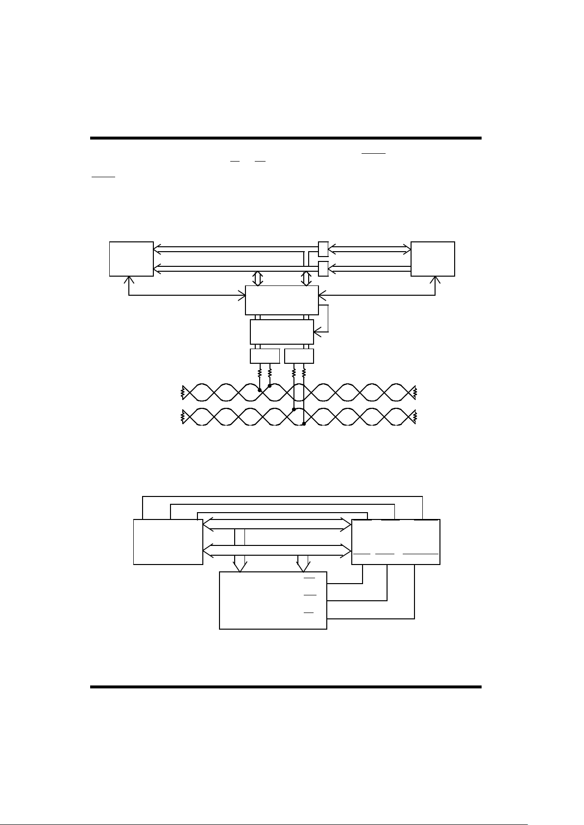
1553 BUS
BUS B
BUS A
XFMRXFMR
(DUAL REDUNDANT)
BCRTMP
CONTROL/ARBITRATIONCONTROL
CPU
HOST
BUFFERS
16 ADDRESS
16 DATA
RAM
DUAL
TRANSCEIVER
TRANSMITTER
TIMEOUT
Figure 3b. CPU/BCRTMP Interface -- Pseudo-Dual-Port RAM Configuration

BCRTMP-28
Register Access
Registers 0 through 15 are accessed with the decode of the
four LSBs of the Address bus (A0-A3) and asserting CS.
Pulse either RD or WR for multiple register accesses.
5.4 RAM Interface
The BCRTMP’s RRD, RWR, and MEMCSO signals serve
as read and write controls during BCRTMP memory
accesses. The host subsystem signals RD, WR, and
MEMCSI propagate through the BCRTMP to become RRD,
RWR, and MEMCSO outputs to support a pseudo-dualport. During BCRTMP-RAM data transfers, the host
subsystem’s memory signals are ignored until the BCRTMP
access is complete.
5.5 Legalization Bus
In the RT mode, when the UT1553 BCRTMP receives a
command on the 1553 bus, it must determine whether that
command is legal. The BCRTMP provides two methods for
the designer to accomplish this task. With the first method,
called DMA Legalization, the BCRTMP automatically
accesses a specific Descriptor Block when it receives a
command to a given subaddress (or mode code). This
Descriptor Block (see figure 4a) contains information that
the BCRTMP uses to determine if the command is legal or
illegal. With the second method, called Bus Legalization,
the 1553 Command Word, minus the RT Address, is routed
to the Legalization bus outputs of the BCRTMP (see figure
4b). The BCRTMP uses this information, for example, as a
PROM address. The single-bit output from the PROM then
feeds the LGLCMD input signal of the BCRTMP (see figure
4c). If the command is legal, the PROM output is high; if
the command is illegal, the PROM output is low. Figure 31
shows the required timing for the BCRTMP
Legalization bus.
1553 BUS
BUS B
BUS A
XFMRXFMR
DUAL
TRANSCEIVER
MEMORY
ARBITRATION
CONTROL
ADDRESS
DATA
BCRTMP CPU
RAM
BUFFER
Figure 3d. CPU/BCRTMP Interface -- DMA Configuration

BCRTMP-29
The Descriptor Pointer Register (Register
2) combined with the Command Word
generates the address of the Control
Word for the Descriptor Block fetch. The
Control Word contains Legalization
information.
Figure 4a. BCRTMP Descriptor Block Legalization
RAM
Control Word
Message Status Pointer
Data List Pointer
Unused
Control Word
Message Status Pointer
Data List Pointer
Unused
Control Word
Message Status Pointer
Data List Pointer
Unused
Descriptor Block
Last Mode Code
Descriptor Block
Descriptor Block
First Receive Subaddress
Second Receive Subaddress
BCRTMP
DMA fetch of three words
when command is received.
2
SYNC
1
COMMAND
3
COMBINATIONAL
LOGIC
Figure 4b. BCRTMP Legalization Bus
15 14 13 12 11 10 9 8 7 6 5 4 3 2 1 0 P
1553 Command Word
BIT TIME
4 5 6 7 8 9 10 11 12 13 14 15 16 17 18 19 20
RT ADDRESS SUBADDRESS/
MODE
WORD COUNT
OR MODE CODE
T/R
LGL0
LGL1
LGL2
LGL3
LGL4
LGL5
LGL6
LGL7
LGL8
LGL9
LGL10
MC
BRDCAST
COMBINATIONAL
LOGIC

BCRTMP-30
To facilitate on-board programming of the 5-volt
EEPROMs on the host board, the BCRTMP places the
Legalization bus into the high-impedance state when the
user asserts the MRST signal.
5.6 Transmitter/Receiver Interface
The BCRTMP’s Manchester II encoder/decoder interfaces
directly with the 1553 bus transceiver, using the TAO-TAZ
and RAZ-RAO signals for Channel A, and TBO-TBZ and
RBZ-RBO signals for Channel B.
The BCRTMP also provides TIMRONA and TIMRONB
signal outputs and an active channel output indicator
(CHA/B) to assist in meeting the MIL-STD-1553B fail-safe
timer requirements (see figure 5).
ADDRESS
DECODER
Figure 4c. BCRTMP Bus Legalization Example
FIFO
BCRTMP
LEGALIZATION
PROM
DATA
OUT
SHIFT
OUT
SHIFT
IN
DATA
IN
ERR
LGL0 - LGL4
LEGALIZATION
BUS
LGLEN
LGLCMD
MICROPROCESSOR
RAM
ADDRESS BUS
DATA BUS
OPTIONAL FOR A3818 MESSAGE
ERROR LOGGING
5
5
BCRTMP
CHANNEL A CHANNEL B
DUAL
TXINHA
TXINHB
CHANNEL A CHANNEL B
TRANSCEIVER
TIMRONA
TIMRONB
CHA/B
Figure 5. Dual-Channel Transceiver

BCRTMP-31
6.0 REMOTE TERMINAL ARCHITECTURE
The Remote Terminal architecture is a descriptorbased configuration of relevant parameters. It is composed
of an RT Descriptor Space (see figure 6) and internal, hostprogrammable registers. The Descriptor Space contains
only descriptors. Descriptors contain programmable
subaddress parameters relating to handling message
transfers. Each descriptor consists of four words: (1) a
Control Word, (2) a Message Status List Pointer, (3) a Data
List Pointer, and (4) an unused fourth word (see figure 7.)
These words indicate how to perform the data transfers
associated with the designated subaddress.
A receive descriptor and a transmit descriptor are associated
with each subaddress. The descriptors reside in memory and
are listed sequentially by subaddress. By using the index
within the descriptor, the BCRTMP can buffer incoming and
outgoing messages, which reduces host CPU overhead. This
message buffering also reduces the risk of incoming
messages being overwritten by subsequent incoming
messages.
Each descriptor contains a programmable interrupt structure
for subsystem notification of user-selected message
transfers and indicates when the message buffers are full.
Illegalizing subaddresses, in normal and broadcast modes,
is accomplished by using programmable bits within the
descriptor (see the RT Functional Operation section below).
Message Status information -- including word count, an
internally generated time tag, and broadcast and message
validity information -- is provided for each message. The
Message Status Words are stored in a separate Message
Status Word list according to subaddress. The list’s starting
locations are programmable within the descriptor.
Message data, received or transmitted, is also stored in lists.
The message capacity of the lists and the lists’ locations are
user selectable within the descriptor.
6.1 RT Functional Operation
The RT off-loads the host computer of all routine data
transfers involved with message transfers over the 1553 bus
by providing a wide range of user-programmable functions.
These functions make the BCRTMP’s operation flexible for
a variety of applications. The following paragraphs give
each function’s operational descriptions.
6.1.1 RT Subaddress Descriptor Definition
The host sets words within the descriptor. The BCRTMP
then reads the descriptor words when servicing a command
corresponding to the specified descriptor. All bit-selectable
functions are active high and inhibited when low.
#’S 15 & 31
#’S 1 & 17
#’S 0 & 16
- STARTING ADDRESS
INITIALIZED BY CPU
IN THE RT DESCRIPTOR
TRANSMIT
SUBADDRESS
SUBADDRESS
SUBADDRESS
SUBADDRESS
SUBADDRESS
#1
#2
#31
#1
#2
#31SUBADDRESS
MODE CODE
MODE CODE
MODE CODE
RECEIVE
RECEIVE
RECEIVE
UNUSED
TRANSMIT
TRANSMIT
UNUSED
SPACE REGISTER
Figure 6. Descriptor Space
FOR FUTURE EXPANSION
DATA LIST POINTER
MESSAGE STATUS LIST POINTER
INDEX
06815
UNUSED II
10
I I
9 7
ILLEGAL BROADCAST
SUBADDRESS
ILLEGAL
INTERRUPT WHEN
ADDRESSED
INTERRUPT WHEN
INDEX = 0
SUBADDRESS
Figure 7. Remote Terminal Subaddress Descriptor

BCRTMP-32
A. Control Word. The first word in the descriptor, the Control Word, selects or disables message transfers and selects
an index.
Bit
Number Description
BITs 15-11 Reserved.
BIT 10 Illegal Broadcast Subaddress. Indicates to the BCRTMP not to access this subaddress using broadcast
commands. The Message Error bit in the status word is set if the illegal broadcast subaddress is addressed.
Since transmit commands do not apply to broadcast, this bit applies only to receive commands.
BIT 9 Illegal Subaddress. Set by the host CPU, it indicates to the BCRTMP that a command with this subaddress is
illegal. If a command uses an illegal subaddress the Message Error bit in the 1553 status word is set. The Illegal
Command Interrupt is also asserted if enabled.
BIT 8 Interrupt Upon Valid Command Received. Indicates that the BCRTMP is to assert an interrupt every time a
command addresses this descriptor. The interrupt occurs just prior to post-command descriptor updating.
BIT 7 Interrupt When Index = 0. Indicates that the BCRTMP initiates an interrupt when the index is decremented
to zero.
BITs 6-0 Index. These bits are for indexed message buffering. Indexing means transacting a pre-specified number of
messages before notifying the host CPU. After each message transaction, the BCRTMP decrements the index by
one until index = 0. Note that the index is decremented for messages that contain message errors.
B. Message Status List Pointer. The host sets the Message Status List Pointer, the second word within the descriptor, and the
BCRTMP uses it as a starting address for the Message Status List. It is incremented by one with each Message Status Word
write. If the Control Word Index is already equal to zero, the Message Status List Pointer is not incremented and the previous
Message Status Word is overwritten.
Note: A Message Status Word is written and the pointer is incremented when the BCRTMP detects a message error.
C. Data List Pointer. The Data List Pointer is the third word within the descriptor. The BCRTMP stores data in RAM beginning
at the address indicated by the Data List Pointer. The Data List Pointer is updated at the end of each successful message with
the next message’s starting address with the following exceptions:
• If the message is erroneous, the Data List Pointer is not updated. The next message overwrites any data
corresponding to the erroneous message.
• Upon receiving a message, if the index is already equal to zero, the Data List Pointer is not
incremented and data from the previous message is overwritten.
D. Reserved. The fourth descriptor word is reserved for future use.

BCRTMP-33
6.1.2 Message Status Word
Each message the BCRTMP transacts has a corresponding
Message Status Word, which is pointed to by the Message
Status List Pointer of the Descriptor. This word allows the
host CPU to evaluate the message’s validity, determine the
word count, and calculate the approximate time frame in
which the message was transacted (figures 8 and 9).
Message Status Word Definition
Bit
Number Description
BIT 15 Subsystem Failed. Indicates SSYSF was asserted before the Message Status Word transfer to memory. This
bit is also set when the user sets bit 13 of Register 10.
BIT 14 Broadcast Message. Indicates that the corresponding message was received in the broadcast mode.
BIT 13 Message Error. Indicates a message is invalid due to improper synchronization, bit count, word count, or
Manchester error.
BITs 12-8 Word Count. Indicates the number of words in the message and reflects the Word Count field in the command
word. Should the message contain a different number of words than the Word Count field, the Message Error
flag is triggered. If there are too many words, they are withheld from RAM. If the actual word count is less than
it should be, the Message Error bit in the 1553 status word is set.
BITs 7-0 Time Tag. The BCRTMP writes the internally generated Time Tag to this location after message completion.
The resolution is 64µs. (See Register 13). If the timer reads 2, it indicates the message was completed 128 to
191µs after the timer started.
ASSERTED DURING THIS MESSAGE
MESSAGE ERROR
MESSAGE WAS BROADCASTED
SUBSYSTEM FAIL INPUT WAS
Figure 8. Message Status Word
WORD COUNT TIME TAG
15 14 13 12 8 7 0
MESSAGE
MESSAGE
MESSAGE
MESSAGE
MESSAGE
(FROM RT DESCRIPTOR)
Figure 9. Remote Terminal Data and Message Status List
#5
#4
#3
#2
#1
#5
#4
#3
#2
#1
LIST
MESSAGE STATUS WORD
DATA LIST
POINTER
DATA LIST
LIST POINTER
MESSAGE STATUS

BCRTMP-34
6.1.3 Mode Code Descriptor Definition
Mode codes are handled similarly to subaddress
transactions. Both use the four-word descriptors residing in
the RT descriptor space to allow the host to program their
operational mode. Corresponding to each mode code is a
descriptor (see figure 10a). Of the 32 address combinations
for mode codes in MIL-STD-1553, some are clearly defined
functions while others are reserved for future use. Sixteen
descriptors are used for mode code operations with each
descriptor handling two mode codes: one mode code with
an associated data word and one mode code without an
associated data word. All mode codes can be handled in
accordance with MIL-STD-1553B. The function of the first
word of the Mode Code Descriptor is similar to that of the
Subaddress Descriptor and is defined below. The remaining
three words serve the same purpose as in the
Subaddress Descriptor.
Control Word
Bit
Number Description
BIT 15 Interrupt on Reception of Mode Code (without Data Word).
BIT 14 Illegalize Broadcast Mode Code (without Data Word).
BIT 13 Illegalize Mode Code (without Data Word).
BIT 12 Reserved.
BIT 11 Illegalize Broadcast Mode Code (with Data Word).
BIT 10 Illegalize Transmit Mode Code (with Data Word).
BIT 9 Illegalize Receive Mode Code (with Data Word).
BIT 8 Interrupt on Reception of Mode Code (with Data Word).
BIT 7 Interrupt if Index = 0.
BITs 6-0 Index. Functionally equivalent to the index described in the Subaddress Descriptor. It applies to mode codes with
data words only.
Figure 10a. (RT) Mode CodeDescriptor Space
RTDSSA + 320
MODE CODE
MODE CODE
MODE CODE (RTDSSA) + 256
STARTING ADDRESS
DESCRIPTOR SPACE
REMOTE TERMINAL
#’S 15 & 31
#’S 2 & 18
#’S 1 & 17
#’S 0 & 16
MODE CODE
Note:
Mode code descriptor blocks are also provided for reserved mode
codes but have no associated predefined BCRTMP operation.
15 14 13 12 11 10 9 8 7 6 0
MESSAGE STATUS LIST POINTER
DATA LIST POINTER
RESERVED
INDEX
ILLEGALIZE BROADCAST MODECODE
(WITHOUT DATA WORD)
INTERRUPT ON RECEPTION OF MODE CODE
(WITHOUT DATA WORD)
ILLEGALIZE MODE CODE
(WITHOUT DATA WORD)
RESERVED
ILLEGALIZE BROADCAST MODECODE
(WITH DATA WORD)
ILLEGALIZE RECEIVE MODE CODE
(WITH DATA WORD)
INTERRUPT ON RECEPTION OF MODE CODE
(WITH DATA WORD)
INTERRUPT IF INDEX = 0
ILLEGALIZE TRANSMIT MODE CODE
(WITH DATA WORD)
Figure 10b. (RT) Mode CodeDescriptor

BCRTMP-35
The descriptors, numbered sequentially from 0 to 15,
correspond to mode codes 0 to 15 without data words and
mode codes 16 to 31 with data words. For example, mode
codes 0 and 16 correspond to descriptor 0 and mode codes
1 and 17 correspond to descriptor 1. The Mode Code
Descriptor Space is appended to the Subaddress Descriptor
Space starting at 0100H (256D) of the 320-word RT
Descriptor Space (see figure 6).
The BCRTMP can autonomously support all mode codes
without data words by executing the specific function and
transmitting the 1553 status word. The subsystem provides
the data word for mode codes with data words (see the Data
List Pointer section). For all mode codes, an interrupt can
be asserted by setting the appropriate bit in the control word
upon successful completion of the mode command (see
figure 10b).
Dynamic Bus Control #00000
This mode code is accepted automatically if the Dynamic
Bus Control Enable bit in the Remote Terminal Address
Register is set. Setting the Dynamic Bus Control
Acceptance bit in the 1553 status word and BCRTMP Status
Register confirms the mode code acceptance. A HighPriority Interrupt is also asserted if enabled. If the Dynamic
Bus Control Enable bit is not set, the BCRTMP does not
accept Dynamic Bus Control.
Synchronize (Without Data Word) #00001
If enabled in the Mode Code #00001 Descriptor Control
Word, the BCRTMP asserts an interrupt when this mode
code is received.
Transmit Status Word #00010
The BCRTMP automatically transmits the 1553 status word
corresponding to the last message transacted.
Initiate Self-Test #00011
The BCRTMP automatically starts its BIT routine. An
interrupt, if enabled, is asserted when the test is completed.
The BIT Word Register and external pin BCRTF are updated
when the test is completed. A failure in BIT will also set the
TF status word bit.
Transmitter Shutdown #00100
The BCRTMP disables the channel opposite the channel on
which the command was received.
Override Transmitter Shutdown #00101
The BCRTMP enables the channel previously disabled.
Inhibit Terminal Flag Bit #00110
The BCRTMP inhibits the Terminal Flag from being set in
the status word.
Override Inhibit Terminal Flag Bit #00111
The BCRTMP disables the Terminal Flag inhibit.
Reset Remote Terminal #01000
The BCRTMP automatically resets the encoder, decoders,
and protocol logic.
Transmit Vector Word #10000
The BCRTMP transmits the vector word from the location
addressed by the Data List Pointer in the Mode Code
Descriptor Block.
Synchronize (with Data Word) #10001
On receiving this mode code, the BCRTMP simply stores
the associated data word.
Transmit Last Command #10010
The BCRTMP transmits the last command executed and the
corresponding 1553 status word.
Transmit BIT Word #10011
The BCRTMP transmits BIT information from the
BIT Register.
Selected Transmitter Shutdown #10100
On receiving this mode code, the BCRTMP simply stores
the associated data word.
Override Selected Transmitter Shutdown #10101
On receiving this mode code, the BCRTMP simply stores
the associated data word.
Mode codes 9-15 and 22-31 are reserved for future
expansion of MIL-STD-1553.
6.2 RT Error Detection
In accordance with MIL-STD-1553, the remote terminal
handles superseding commands on the same or opposite bus.
When receiving, the Remote Terminal performs a response
time-out function of 56ms for RT-RT transfers. If the
response time-out condition occurs, a Message Error bit can
be set in the 1553 status word and in the Message Status
Word. Error checking occurs on both of the Manchester
logic and the word formats. Detectable errors include word
count errors, long words, short words, Manchester errors
(including zero crossing deviation), parity errors, and data
discontiguity.
6.3 RT Operational Sequence
The following is a general description of the typical
behavior of the BCRTMP as it processes a message in the
RT mode. It is assumed that the user has already written a
“1” to Register 0, bit 0, enabling RT operation.

BCRTMP-36
Valid Command Received.
COMSTR goes active
Bus Legalization occurs (if selected)
DMA Descriptor Read. (If Bus Legalization is used,
the BCRTMP ignores the legalization information in
the Control Word). After receiving a valid command,
the BCRTMP initiates a burst DMA:
DMA arbitration (BURST)
Control Word read
Message Status List Pointer read
Data List Pointer read
Data Transmitted/Received.
• Data Word DMA.
If the BCRTMP needs to transmit data from
memory, it initiates a DMA cycle for each Data
Word shortly before the Data Word is needed on
the 1553B bus:
DMA arbitration
Data Word read (starting at Data List
Pointer address, incremented for each
successive word)
If the BCRTMP receives data, it writes each Data
Word to memory after the Data Word is received:
DMA arbitration
Data Word write (starting at Data List
Pointer address, incremented for each
successive word)
Status Word Transmission.
The BCRTMP automatically transmits the Status
Word as described in section 8.2.8. For illegalized
commands, the BCRTMP also sets the Message
Error Bit in the 1553 Status Word.
Exception Handling.
If an interrupting condition occurs during the
message, the following occurs:
For High-Priority Interrupts:
HPINT is asserted (if enabled in Register 7).
For message errors, the BCRTMP is put in
a hold state until the interrupt is
acknowledged (by writing a “1” to the
appropriate bit in Register 8).
For Standard Interrupts:
DMA arbitration (BURST)
Interrupt Status Word write
RT Descriptor Block Pointer write
Tail Pointer read (into Register 6)
STDINTP pulses low
STDINTL asserted (if enabled)
Processing continues
• Descriptor Write.
After the BCRTMP processes the message, a final
DMA burst occurs to update the descriptor block,
if necessary:
DMA arbitration (BURST)
Message Status Word write
Data List Pointer write (incremented by
word count)
Message Status List Pointer write
(incremented by 1)
Control Word write (index decremented)
Note the following exceptions:
Mode codes without data require no
descriptor update.
Illegalized commands require no
description updates (or data word accesses).
Predefined mode codes (18 and 19) which
do not require access to memory for the data
word, do not involve updating the Data
List Pointer.
Messages with errors prevent updates to the
Data List Pointer.
If the message index was zero, neither the
Message Status List Pointer nor the Data
List Pointer is updated.
7.0 BUS CONTROLLER ARCHITECTURE
The BCRTMP’s bus controller architecture is based on a
Command Block structure and internal, hostprogrammable registers. Each message transacted over the
MIL-STD-1553 bus has an associated Command Block,
which the CPU sets up (see figures 11 and 12). The
Command Block contains all the relevant message and RT
status information as well as programmable function bits
that allow the user to select functions and interrupts. This
memory interface system is flexible due to a doubly-linked
list data structure
Figure 11. Command Block
HEAD POINTER
CONTROL WORD
COMMAND WORD 1
COMMAND WORD 2 (RT-RT ONLY)
DATA LIST POINTER
STATUS WORD 1
STATUS WORD 2 (RT-RT ONLY)
TAIL POINTER

BCRTMP-37
In a doubly-linked Command Block structure, pointers
delimit each Command Block to the previous and
successive blocks (see figure 13). The linking feature eases
multiple message processing tasks and supports message
scheduling because of its ability to loop through a series of
transfers at a predetermined cycle time. A data pointer in
the command allows efficient space allocation because data
blocks only have to be configured to the exact word count
used in the message. Data pointers also provide flexibility
in data-bank switching.
A control word with bit-programmable functions and a
Message Error bit are in each Command Block. This allows
selecting individual functions for each message and
provides message validity information. The BCRTMP’s
register set provides additional global parameters and
address pointers.
A programmable auto retry function is selectable from the
control word and Control Register.
The auto retry can be activated when any of the following
occurs:
• Busy bit set in the status word
• Message Error (indicated by the RT status response)
• Response Time-Out
• Message Error detected by the Bus Controller
One to four retries are programmable on the same or
opposite bus.
The Bus Controller also has a programmable intermessage
delay timer that facilitates message transfer scheduling (see
figures 14 and 15). This timer, programmed in the control
word, automatically delays between the start of two
successive commands.
A polling function is also provided. The Bus Controller,
when programmed, compares incoming status words to a
host-specified status word and generates an interrupt if the
comparison indicates any matching bits. An Interrupt and
Continue function facilitates the host subsystem’s
synchronization by generating an interrupt when the
specified Command Block’s message is executed.
7.1 BC Functional Operation
The Bus Controller off-loads the host computer of many
functions needed to coordinate 1553 bus data transfers.
Special architectural features provide message- by-message
flexibility. In addition, a programmable interrupt scheme,
programmable intermessage timing delays, and internal
registers enhance the BCRTMP’s operation.
The host determines the first Command Block by setting the
initial starting address in the current Command Block
Register. Once set, the BCRTMP updates the current
Command Block register with the next Command Block
Address. The BCRTMP then executes the sequential
Command Blocks and counts out message delays (where
programmed) until it encounters the last Command Block
listed (indicated by the End of List bit in the control word).
Interrupts are asserted when enabled events occur (see
section 9.0, Exception Handling and Interrupt Logging).
The functions and their programming instructions are
described below. The registers also contain many
programmable functions and function parameters.
X
X IS BETWEEN 1 & 32
LAST DATA WORD
DATA WORD #2
DATA WORD #1
DATA LIST POINTER
COMMAND BLOCK
Figure 12. Data Placement
COMMAND BLOCK #1
HP
TP
#2
HP
TP
#3
HP
TP
#4
HP
TP
Figure 13. Command Block Chaining

BCRTMP-38
BC Command Block Definition
Each Command Block contains (see figure 11):
A. Head Pointer. Host-written, this location can contain the address of the previous Command Block’s Head Pointer. The
BCRTMP does not access this location.
B. Control Word. Host-written, the Control Word contains bit-selectable options and a Message Error bit the BCRTMP
provides (see figure 14). The bit definitions follow.
Bit
Number Description
BIT 15 Message Error. The BCRTMP sets this bit when it detects an invalid RT response as defined in
MIL-STD 1553B.
BIT 14 Skip. When set, this bit instructs the BCRTMP to skip this Command Block and execute the next.
BIT 13 Interrupt and Continue. If set, a Standard Interrupt is asserted when this block is addressed; operation,
however, continues. Note that this interrupt must also be enabled by setting bit 0 of Register 9.
BIT 12 Polling Enable. Enables the BCRTMP’s polling operation.
BIT 11 Auto Retry Enable. When set, the Auto Retry function, governed by the global parameters in the Control
Register, is enabled for this message.
BIT 10 End of List. Set by the CPU, this bit indicates that the BCRTMP, upon completion of the current message,
will halt (Register 1, bit 0 goes inactive) and assert a High-Priority Interrupt. The interrupt must also be
enabled in theHigh-Priority Interrupt Enable Register.
BIT 9 RT-RT. Set by the CPU, this indicates that this Command Block transacts an RT-RT transfer.
BIT 8 Monitor RT-RT Transfer. Set by the CPU, this function indicates that the BCRTMP should receive and store
the message beginning at the location indicated by the data pointer.
BITs 7-0 Time Delay. The CPU sets this field, which causes the BCRTMP to delay the specified time between sequential
message starts (see figures 14 and 15). Regardless of the value in the Time Delay field (including zero), The
BCRTMP will at least meet the minimum 4µs intermessage gap time as specified in MIL-STD-1553B. The
timer is enabled by having a non-zero value in this bit field. When using this function, please note:
• Timer resolution is 16µs. As an example, if a given message requires 116µs to complete (including the
minimum 4ms intermessage gap time) the value in the Time Delay field must be at least 00001000 (8 x
16µs = 128µs) to provide an intermessage gap greater than the 4ms minimum requirement.
• If the timer is enabled and the Skip bit is set, the timer provides the programmed delay before proceeding.
• If the message duration exceeds the timer delay, the message is completed just as if the time were
not enabled.
‘TIME DELAY’
TRANSFER
RT-RT
MONITOR
TRANSFER
RT-RT
LIST
OF
END
ENABLE
RETRY
AUTO
ENABLE
POLLING
CONTINUE
AND
INTERRUPT
ERROR
MESSAGE
SKIP
15 14 13 12 11 10 9 8 7 0
Figure 14. Command Word
Figure 15. BC Timing Delays
MESSAGE #1 MESSAGE #2 MESSAGE #3
T
DELAY1
T
DELAY2

BCRTMP-39
C. Command Word One. Initialized by the CPU, this location contains the first command word corresponding to the
Command Block’s message transfer.
D. Command Word Two. Initialized by the CPU, this location is for the second (transmit) command word in RT-RT
transfers. In messages involving only one RT, the location is unused.
E. Data Pointer. Initialized by the CPU, this location contains the starting location in RAM for the Command Block’s
message (see figure 16).
F. Status Word One. Stored by the BCRTMP, this location contains the entire Remote Terminal status response.
G. Status Word Two. Stored by the BCRTMP, this location contains the receiving Remote Terminal status word. For
transfers involving one Remote Terminal, the location is unused.
H. Tail Pointer. Initialized by the host CPU, the Tail Pointer contains the next Command Block’s starting address.
7.2 Polling
During a typical polling scenario (see figure 17) the Bus
Controller interrogates remote terminals by requesting them
to transmit their status words. This feature can also alert the
host if a bit is set in any RT status word response during
normal message transactions. The BCRTMP enables the
host to initialize a chain of Command Blocks with the
command word’s Polling Enable bit. A programmable
Polling Compare Register (PCR) is provided. In the polling
mode, the Remote Terminal response is compared to the
Polling Compare Register contents. Program the PCR by
setting the PCR bits corresponding to the RT’s 1553 status
word bits to be compared. If they match (i.e., two 1’s in the
same bit position) then, if enabled in both the BC Command
Block Control Word and in the Standard Interrupt Enable
Register (Register 9), a polling comparison interrupt
is generated.
Example 1. No bit match is present
PCR 0000000001
RT’s 1553 Status Word response 0000010000
Result No Polling Comparison Interrupt
Example 2. Bit match is present
PCR 0010010000
RT’s 1553 Status Word response 00000100000
Result Polling Comparison Interrupt
7.3 BC Error Detection
The Bus Controller checks for errors on each message
transaction. In addition, the BC compares the RT command
word addresses to the incoming status word addresses. The
BC monitors for response time-out and checks data and
control words for proper format according to MIL-STD-
1553. Illogical commands include incorrectly formatted
RT-RT Command Blocks.
Figure 16. Contiguous Data Storage
COMMAND BLOCK #1
DATA POINTER
COMMAND BLOCK #2
DATA POINTER
MESSAGE #1
MESSAGE #2
RAM
DATA WORD #1
DATA WORD #2
DATA WORD #3
DATA WORD #1
DATA WORD #2
DATA WORD #3
DATA WORD #4
RT
BC
RESPONSE
Q?
RTRT
POLLING RESPONSE REGISTER
(RT STATUS WORD)
POLLING COMPARE WORD
(SET BY CPU)
Figure 17. Polling Operation

BCRTMP-40
7.4 Bus Controller Operational Sequence
The following is a general description of the typical
behavior of the BCRTMP as it processes a message in the
BC mode.
The user starts BC operation by writing a “1” to Register 0,
Bit 0.
• Command Block DMA - the following occurs
immediately after Bus Controller startup:
DMA arbitration (BURST)
Control Word read
Command Word 1 read (from third location
of Command Block)
Data List Pointer read
A. For BC-to-RT Command Blocks:
The BCRTMP transmits the Command Word.
• Data Word DMA
DMA arbitration
Data Word read (starting at Data List Pointer
address, incremented for each successive
word)
The BCRTMP transmits the Data Word. Data Word
DMAs and transmissions continue until all Data Words
are transmitted.
• Status Word DMA
The BCRTMP receives the RT Status Word.
DMA arbitration
Status Word write (to sixth location of
Command Block)
B. For RT-to-BC Command Blocks:
The BCRTMP transmits the Command Word.
• Status Word DMA
The BCRTMP receives the RT Status Word.
DMA arbitration
Status Word write (to sixth location of
Command Block)
The BCRTMP receives the first Data Word.
• Data Word DMA
DMA arbitration
Data Word write (starting at Data List
Pointer address, incremented for each
successive word)
Data Word receptions and DMAs continue until all Data
Words are received.
C. For RT(A)-to-RT(B) Command Blocks:
The BCRTMP transmits Command Word 1 to RT(B).
• Command Word 2 DMA
DMA arbitration
Command Word 2 read (from fourth
location of Command Block)
The BCRTMP transmits Command Word 2 to RT(A).
The BCRTMP receives the RT Status Word from RT(A).
• Status Word DMA for RT(A) Status Word
DMA arbitration
Status Word write (to sixth location of
Command Block)
The BCRTMP receives the first Data Word
• Data Word DMA (only if the BCRTMP is enabled
to monitor the RT-to-RT message).
DMA arbitration
Data Word write (starting at Data List
Pointer address, incremented for each
successive word)
Data Word receptions and DMAs continue until all Data
Words are received.
The BCRTMP receives the RT Status Word from RT(B).
• Status Word DMA for RT(B) Status Word
DMA arbitration
Status Word write (to seventh location of
Command Block)
Exception Handling.
If an interrupting condition occurs during the message,
the following occurs:
For High-Priority Interrupts:
HPINT is asserted (if enabled in Register 7). For
message errors, the BCRTMP is put in a hold state until
the interrupt is acknowledged (by writing a “1” to the
appropriate bit in Register 8).
For Standard Interrupts:
DMA arbitration (BURST)
Interrupt Status Word write
Command Block Pointer write
Tail Pointer read (into Register 6) STDINTP
pulses low
STDINTL asserted (if enabled)
Processing continues

BCRTMP-41
If Retries are enabled and a Retry condition occurs, the
following DMA occurs:
DMA arbitration (BURST)
Control Word read
Command Word 1 read (from third location
of Command Block)
Data List Pointer read
The BCRTMP proceeds from the current Command Block
to the next successive Command Block.
• If no Message Error has occurred during the
current Command Block, the following occurs:
DMA arbitration (BURST)
Command Block Tail Pointer read (to
determine location of next Command
Block. Note that this occurs only if no
Retry).
DMA hold cycle
Control Word read (next Command Block)
Command Word 1 read (next Command
Block)
Data List Pointer read
• If the BCRTMP detects a Message Error while
processing the current Command Block, the
following occurs:
DMA arbitration (BURST)
Control Word write
Command Block Tail Pointer read (to
determine location of next Command
Block. Note that this occurs only if no
Retry.)
DMA hold cycle
Control Word read (next Command Block)
Command Word 1 read (next Command
Block)
Data List Pointer read
The BCRTMP proceeds again from point A, B, or C as
shown above.
7.5 BC Operational Example (figure 19 on page 49)
The BCRTMP is programmed initially to accomplish the
following:
The first Command Block is for a four-word RT-RT transfer
with the BCRTMP monitoring the transfer and storing
the data.
• Auto-retry is enabled on the opposite bus using only one
retry attempt, if the incoming Status Word is received
with the Message Error bit set.
• Wait for a time delay of 400ms before proceeding to the
next Command Block.
• The Data List Pointer contains the address 0400H.
The second Command Block is for a BC-RT transfer of
two words.
• The End of List bit is set in its Control Word.
• The Data List Pointer contains the address 0404H.
• The Polling Enable bit is set and the Polling Compare
Register contains 0004H (check for Subsystem Fail bit.
Then:
A. The CPU initializes all the appropriate registers and
Command Blocks, and issues a Start Enable by writing a
“1” to Register 0, bit 0.
B. The BCRTMP, through executing a DMA cycle, reads
the Control Word, Command Words, and the Data List
Pointer. The delay timer starts and message execution
begins by transmitting the receive and transmit
commands stored in the Command Blocks. The
BCRTMP then waits to receive the Status Word back
from the transmitting RT.
C. The BCRTMP receives the RT Status Word with all
status bits low from the transmitting RT and stores the
Status Word in Command Block 1. The incoming data
words from the transmitting RT follow. The BCRTMP
stores them in memory locations 0400H - 0403H.
If the Status Word indicates that the message cannot be
transmitted (Message Error), the response time-out
clock counts to zero and the allotted message time runs
out. An auto-retry can be initiated if programmed to do
so. Nevertheless, the ME bit in the Control Word is set.
D. The BCRTMP receives the Status Word response from
the receiving RT. The ME bit in the Status Word is set,
indicating the message is invalid. The BCRTMP
initiates the auto retry function, (as programmed) on the
alternate bus, re-transmits the Command Words, receives
the correct Status Word, and stores the data again in
locations 0400H - 0403H. This time the Status Word
response from the receiving RT indicates the message
transfer is successful.
E. The timer delay between the two successive
transactions counts down another 135µs before
proceeding. This is determined as follows:
The message transaction time is approximately130µs
(the only approximation is due to the range in status
response and intermessage gap times specified by

BCRTMP-42
MIL-STD-1553B). Approximating that with the retry,
the total duration for the two attempts is 265ms.
F. The BCRTMP reads the Tail Pointer of Command
Block 1 and places it in the Current Command Register.
It also reads the Control Word, Command Word, and
Data List Pointer, and the first data word in the second
Command Block.
G. Since this is a BC-RT transfer, the BCRTMP transmits
the receive command followed by two data words from
locations 0404H - 0405H in memory. The BCRTMP
reads the second data word from memory while
transmitting the first.
H. The BCRTMP receives the status response from the RT.
In this case, the Status Word indicates, by the ME bit
being low, that the message is valid. The Status Word
also has the Subsystem Fail bit set.
I. The Status Word is stored in the Command Block. The
BCRTMP, having encountered the end of the list, halts
message transactions and waits for another start signal.
J. The BCRTMP asserts a High-Priority Interrupt
indicating the end of the command list. Due to the
polling comparison failure, the BCRTMP also asserts a
Standard Priority Interrupt and logs the event in the
Interrupt Log List.
8.0 MULTIPLE PROTOCOL OPTIONS
The UT1553 BCRTMP was developed from the industry’s
first monolithic MIL-STD-1553B Bus Controller and
Remote Terminal chip, the UT1553B BCRT. Many
additional features were added to the BCRT to create the
UT1553 BCRTMP, which conforms to the requirements of
the many different “1553 standards” which developed
between releases of MIL-STD-1553A and
MIL-STD-1553B.
User-configurable Operational Mode selections allow the
BCRTMP to interface to a wide variety of 1553 protocols.
Protocols for which the user can configure the UT1553
BCRTMP include: MIL-STD-1553A, MIL-STD-1553B,
McDonnell Douglas A3818, A5232, and A5690, and
Grumman Aerospace SP-G-151A. The user need only to
determine which Operational Mode settings are necessary
to conform to the application’s needs.
8.1 Operational Modes
The user can program the BCRTMP to conform to many of
the currently used MIL-STD-1553 variations in protocol by
simply selecting different operating modes. The BCRTMP
provides seven Mode Select input pins and/or register bits t
to select the different operating modes. If all mode bits are
high, the BCRTMP operates in accordance with
MIL-STD-1553B.
8.1.1 MD0 (Mode 0)
Legalization Select (RT)
The MD0 input pin or bit 0 of Register 14 selects the method
of command legalization the BCRTMP uses. Before issuing
the appropriate RT response to a command, the BCRTMP
must determine whether the command is legal. The
BCRTMP accomplishes command legalization by one of
two methods -- DMA, by fetching the appropriate
Descriptor Block (MD0=1); or by using the Legalization
bus (MD0=0). The Legalization bus is the faster of the two
methods and must be selected in order to meet the RT
Response Time requirements of MIL-STD-1553A. Since
the BCRTMP cannot meet the “A” response time unless it
uses the Legalization bus for command legalization, it
forces Mode 0 low internally if the “A” response time is
selected (MD2=0). See also section 5.5, Legalization bus.
8.1.2 MD1 (Mode 1)
Broadcast Option Select (BC, RT)
The MD1 input pin or bit 1 of Register 14 selects the
Broadcast option the BCRTMP uses. The use of Broadcast
varies with differences in the 1553 protocols. For protocols
that support the Broadcast option (MD1=1), the RT address
11111 is reserved to indicate a Broadcast command. When
the Bus Controller transmits a Broadcast command, all RTs
must receive the message, but no RT is to respond with a
status word. For protocols that do not support the Broadcast
option (MD1=0), RT address 11111 is treated as a normal
RT address.
8.1.3 MD2 (Mode 2)
RT Response Time Select (RT)
The MD2 input pin or bit 2 of Register 14 selects the RT
Response Time the BCRTMP uses in the RT mode to
respond to 1553 commands. Before an RT can respond to a
command, it must determine whether that command is legal.
As stated is section 8.1.1 above, the BCRTMP accomplishes
Command Legalization by using either DMA Descriptor
Block fetching or by using the Legalization bus.
The RT Response Time differs among the 1553 protocols.
The RT Response Time is measured from the zero crossing
of the parity bit of the receive command’s last data word (or
the zero crossing of the parity bit of the transmit command
word) to the status word sync’s zero crossing. The maximum
response time allowed for an RT is either 7.0µs (“A”
response time, MD2=0) or 12.0µs (“B” response time,
MD2=1), depending on the specification.

BCRTMP-43
8.1.4 MD3 (Mode 3)
Mode Code Option Select (BC,RT)
The MD3 input pin or bit 3 of Register 14 selects the mode
code option the BCRTMP uses. Differences in mode code
definitions among the 1553 protocols concern the number
of defined mode codes and whether mode codes with data
are defined. MIL-STD-1553B’s definition is formal, but the
other specifications define the possible mode codes to
varying degrees, and may not use mode codes with data.
The BCRTMP uses this selection to determine which bit
patterns in the subaddress field of the command word
indicate that the word count field contains a mode code.
When MD3 is high, either 00000 or 11111 in the subaddress
field indicates a mode code. When MD3 is low, only 00000
indicates a mode code. The BCRTMP provides additional
control over mode code definition with the MD6 selection
(see section 8.1.7). Also, the user can program bit 13 of
Register 14 to provide additional mode code control.
8.1.5 MD4 (Mode 4)
Status Word Option Select (RT)
The MD4 input pin or bit 4 of Register 14 selects the method
the BCRTMP uses to generate the RT status word. Most, if
not all, 1553 protocols define the Terminal Address,
Message Error (ME), and Terminal Flag (TF) status word
bits in the same manner. The remaining bits are defined in
a variety of ways, not only dependent on the 1553 protocol,
but also on the individual procurement specification. MILSTD-1553B is quite formal in defining the status word bits,
while the other specifications either define or leave
undefined the other bits to varying degrees for procurementspecific options. When MD4 is high, the BCRTMP
generates the status word in accordance with MIL-STD1553B, using the contents of Register 10 for many of the
status bits. When MD4 is low, the BCRTMP generates the
status word using the Programmable status register
(Register 15). See section 8.2.8 for more information
regarding status word generation.
8.1.6 MD5 (Mode 5)
Message Error Technique Select (RT)
The MD5 input pin or bit 5 of Register 14 selects the method
the BCRTMP uses for handling message errors. Some 1553
protocols (e. g., MIL-STD-1553B) consider any message
error reason to discard the entire message and suppress
status word transmission, while others
(e. g., McDonnell Douglas A3818) define the required
activity according to message error severity.
When MD5 is high, message error handling is as described
in MIL-STD-1553B. The MIL-STD-1553B definition
states that on the occurrence of any Message Error
condition, the RT sets the message error bit in the status
word and suppresses status word transmission. Message
error conditions are defined as any of the following: parity
errors, word count errors, or Manchester errors.
When MD5 is low, message error handling is as described
in McDonnell Douglas A3818. In this method, a less severe
error (either a Manchester error or a parity error in a data
word, for example) requires special attention. The RT must
mark the individual defective data word and respond with
the message error bit set in the status word. When the
BCRTMP detects this type of Message Error, the BCRTMP
asserts the ERR output and places the word count for the
defective data word on the least significant five bits of the
Legalization bus. Due to the BCRTMP’s internal detection
circuitry, errors in the first two data bits will force the
BCRTMP to ignore the word and cause a word count error.
Word count errors cause the RT to suppress the status word
and set the Message Error bit.
8.1.7 MD6 (Mode 6)
Mode Code with Data Select (BC,RT)
The MD6 input pin or bit 6 of Register 14 selects whether
mode codes with data are allowed. When MD6 is high, the
mode codes defined in MIL-STD-1553B as mode codes
with data have an associated data word. When MD6 is low,
the BCRTMP treats all mode codes as mode codes
without data.
8.1.8 MD7 (Mode 7)
Remote Terminal Time Out Option Select (BC,RT)
The MD7 input pin or bit 12 of Register 0 selects the Remote
Terminal Time-Out option. When MD7 is high, the Remote
Terminal Time-Out (RTO) is nominally16 µs. When MD7
is low, the Remote Terminal Time-Out (RTO) is
nominally 32µs.
8.2 Additional UT1553 BCRTMP Features
8.2.1 DOMC Do Mode Code Control Signal (RT)
The BCRTMP provides additional mode code flexibility
through use of the DOMC input. This input (internally
pulled high) can be pulled low when the BCRTMP receives
a mode code to prevent the BCRTMP from automatically
executing the mode code. This input can be used to disable
automatic execution of mode codes at any time; however,
the individual selection of mode code execution applies only
when using the Legalization bus for command legalization
(i.e., MD0 is low), since the timing for mode code execution
decision-making corresponds with mode code legalization
using the Legalization bus method only. If the user desires
automatic execution of the mode code as defined in MILSTD-1553B, then the user asserts the DOMC signal high
after the BCRTMP receives the mode code. If the user
desires to suppress automatic execution of the Mode Code,
then the user asserts the DOMC signal low after the
BCRTMP receives the mode code. The timing for the
DOMC input follows, identically, the timing for the
LGLCMD of the Legalization bus. See Table 2 for the
actions the BCRTMP takes when receiving specific
mode codes.

BCRTMP-44
8.2.2 Continuous Wrap-Around Circuitry (BC,RT)
The Continuous Wrap-Around Test feature is available for
both Bus Controller and Remote Terminal operation. This
feature permits continuous monitoring of the correct
operation of the BCRTMP.
The user either asserts the WRAPEN input low or writes a
“one” to bit 7 of Register 14 to enable the Continuous WrapAround feature. This feature permits the BCRTMP to
compare everything it transmits with a “reflected-back”
version of the transmitted data. The data is reflected back
by the 1553 transceiver and serially received into the
BCRTMP’s decoder circuitry. If a mismatch is found
between the transmitted data and the reflected data, then the
BCRTMP asserts the WRAPF output.
Asserting the WRAPEN and the ALTWRAP inputs places
the BCRTMP in a special off-line system diagnostics mode
to allow the system to test both 1553 buses and the
associated transceivers, transformers, connectors, etc.
Typical use of this feature would involve connecting a bus
stub between the Channel A and B connectors. The user
could then place the BCRTMP in a Bus Controller mode of
operation and execute a list of commands. With the
ALTWRAP and WRAPEN signals asserted, each
transmission on the selected bus would be received through
the wrap-around circuitry on the opposite bus. Any assertion
of the WRAPF output would indicate that either the
BCRTMP or some part of the bus or interface network has
failed. Note that if no RT is present in the system, then the
BCRTMP will naturally detect a no-response error. This can
be avoided by using Broadcast commands, in which case no
RT is expected to respond on the bus.
8.2.3 Stop Enable (BC,RT)
The user implements this feature by setting bit 12 of Register
14 high. In the Bus Controller mode, when this bit is high,
the occurrence of any enabled interrupt (either Standard or
High-Priority) causes the BCRTMP to automatically halt
Bus Controller message processing. The BCRTMP resumes
message processing when the user clears the interrupt by
writing a “one” to the appropriate bit in Register 8.
In the Remote Terminal mode, when this bit is high, the
occurrence of any enabled interrupt (either Standard or
High-Priority) causes the BCRTMP to automatically enter
the Forced Busy mode of operation (see section 8.2.4). The
BCRTMP exits the Forced Busy mode when the user clears
the interrupt.
8.2.4 Forced Busy (RT)
The user places the BCRTMP into the Forced Busy mode
(RT only) by either pulling the FBUSY input low or by
writing a “one” to bit 11 of Register 15 or bit 9 of Register
10. As discussed in Section 8.2.3, the BCRTMP can also
automatically enter the Forced Busy mode with the
occurrence of enabled interrupts. While in the Forced Busy
mode, all interrupts are disabled, the Busy bit is set in the
status word response, and no DMA transactions will occur.
The BUSYACK output acknowledges that the BCRTMP is
in the Forced Busy mode.
8.2.5 ACTIVE Signal (RT)
The ACTIVE output provides a means for the user to place
the BCRTMP on the 1553 bus, enabled as an RT, and
determines if it should assume bus mastership. The
BCRTMP asserts the ACTIVE signal when it detects a valid
command on the bus to any RT address. The host determines
which bus is active by examining bits 10 and 11 of Register
14. To disable bus activity detection, the host writes a “one”
to bit 10 of Register 14 to disable Channel A (or bit 11 of
Register 14 for Channel B). The ACTIVE output remains
deasserted until one or both of the channels is enabled. The
user writes a “zero” to the appropriate bit location(s) to
enable the desired channel(s). Performing a programmed or
hardware reset also enables both activity monitors.
8.2.6 Transmitter Inhibit Signals (BC,RT)
The UT1553 BCRTMP contains two transmitter inhibit
signals (one for Channel A and one for Channel B) that
provide fail-safe timing for the 1553 buses. The signals are
active (TIMRONA for Channel A or TIMRONB for
Channel B) when the BCRTMP begins transmitting and
time out, or go inactive, 660µs later, if the BCRTMP has not
completed its transmission.
8.2.7 Immediate Clear Mode
The user sets bit 15 of Register 15 to enter the Immediate
Clear Mode. When set, this bit will cause the BCRTMP to
automatically clear all programmable status bits after the
BCRTMP transmits the RT status word. When this bit is set,
the first status word sent out contains the programmable
status bits as programmed by either the Programmable
Status Register (“A” protocol, MD4 = 0) or the RT Address
Register (“B” protocol, MD4 = 1). After status word
transmission, all programmable status bits are cleared
automatically. The exception to this occurs when the next
command received is the Transmit Status Word or Transmit
Last Command mode code. When either of these mode
codes is received, the BCRTMP will respond with the
appropriate status word from the previous valid command.
This feature applies to all operational modes.
8.2.8 Status Word Generation
As a result of the differing requirements for status words in
the various 1553 protocols, the BCRTMP must be capable
of generating the RT status word in a variety of ways. It is
appropriate to discuss the separate status word bits
individually in order to understand how the BCRTMP
generates these bits. The three status word bits defined as
“reserved” in MIL-STD-1553B are handled identically by
the BCRTMP, as shown below. The action taken to generate

BCRTMP-45
all other status word bits varies, depending on the mode in
which the BCRTMP is operating. In most cases, the
BCRTMP generates the status word bits in different ways
depending on the internal state of Operational Mode 4.
8.2.8.1 The Terminal Address Field
The Terminal Address field in the status word is always
provided in the same manner. The BCRTMP uses pins
RTA4 to RTA0 (or bits 4-0 of the Remote Terminal Address
Register) to generate the Remote Terminal Address bits of
the status word.
8.2.8.2 The Message Error Bit
If MD4 = 1, then the Message Error bit in the status word
is set if any 1553 Message Error condition (or Illegal
Command) occurs.
If MD4 = 0, then the Message Error bit in the status word
is set when any 1553 Message Error condition (or Illegal
Command) occurs or if bit 10 of Register 15 is set.
8.2.8.3 The Instrumentation Bit
If MD4 = 1, then the BCRTMP uses bit 15 of Register 10
to set the Instrumentation bit in the status word.
If MD4 = 0, then the BCRTMP uses bit 9 of Register 15 (the
Programmable Status Register) to set the Instrumentation
bit in the status word.
8.2.8.4 The Service Request Bit
If MD4 = 1, then the BCRTMP uses bit 10 of Register 10
to set the Service Request bit in the status word.
If MD4 = 0, then the BCRTMP uses bit 8 of Register 15 (the
Programmable Status Register) to set the Service Request
bit in the status word.
Also, the Service Request bit can be forced to reflect the
complement of the status word Busy bit (independent of the
internal state of MD4) if the user sets bit 12 of Register
15 high.
8.2.8.5 The MIL-STD-1553B “Reserved” Status
Word Bits
The BCRTMP always provides the MIL-STD-1553B
“Reserved” status word bit field (bit Times 12-14) in the
status word in the same manner. The BCRTMP uses bits
5-7 of the Register 15 to generate these bits (independent of
the internal state of MD4).
8.2.8.6 The Broadcast Command Received Bit
If MD4 = 1, then the Broadcast Command Received bit in
the status word is set when a Broadcast command is
received, if Broadcast is enabled.
If MD4 = 0, then the Broadcast Command Received bit in
the status word is set if bit 4 of the Programmable Status
Register is set high.
8.2.8.7 The Busy Bit
If MD4 = 1, then the Busy bit in the status word is set if
either bit 14 of Register 10 is set high or if the BCRTMP is
in the Forced Busy mode (see section 8.2.4 for a discussion
on entry to the Forced Busy mode). The assertion of the
Busy bit while in the Forced Busy mode can be disabled if
both bits 13 and 14 of Register 15 are set high. Note that the
Forced Busy mode is independent of the internal state
of MD4.
If MD4 = 0, then the Busy bit in the Status Word is set if
either bit 14 of Register 10 or bit 3 of the Programmable
Status Register is set high, or if the BCRTMP is in the Forced
Busy mode.
8.2.8.8 The Subsystem Flag Bit
If MD4 = 1, then the Subsystem Flag bit in the status word
is set either if the user sets bit 13 of Register 10 or asserts
the SSYSF input of the BCRTMP, or if a BIT failure
has occurred.
If MD4 = 0, then the Subsystem Flag bit in the status
word is set if the user sets bit 2 of the Programmable
Status Register.
8.2.8.9 The Dynamic Bus Control Acceptance Bit
If MD4 = 1, the Dynamic Bus Control Acceptance bit in the
status word will be set when the BCRTMP receives a
Dynamic Bus Control Mode Code that is not a Broadcast
command, if the user has not illegalized that command and
has set bit 12 of Register 10 high.
8.2.8.10 The Terminal Flag Bit
If MD4 = 1, setting bit 11 of Register 10 or the occurrence
of a BIT failure will always set the Terminal Flag bit in the
status word.
If MD4 = 0, setting bit 0 of the Programmable Status
Register will always set the Terminal Flag bit in the
status word.
Independent of the internal state of MD4, the following
conditions will also set the Terminal Flag bit in the
status word.
1) If bit 13 of Register 15 is “1”, and bit 14 of
Register 15 is “0”, then the Terminal Flag bit in the
status word is also set if the Busy bit or the
Subsystem Flag bit is set in the status word.
2) If bit 13 of Register 15 is “0” and bit 14 of Register
15 is “1”, then the Terminal Flag bit in the status
word is also set if any of the status word bits are set.
Note that if the Terminal Flag bit has been inhibited by Mode
Code 6, this bit will not be set by any of the above methods.

BCRTMP-46
9.0 EXCEPTION HANDLING AND
INTERRUPT LOGGING
The exception handling scheme the BCRTMP uses is based
on an interrupt structure and provides a high degree of
flexibility in:
• defining the events that cause an interrupt,
• selecting between High-Priority and Standard
interrupts, and
• selecting the amount of interrupt history retained.
The interrupt structure consists of internal registers that
enable interrupt generation, control bits in the RT and BC
data structures (see the Remote Terminal Descriptor
Definition section, page 30, and the Bus Controller
Command Block definition, page 35), and an Interrupt Log
List that sequentially stores an interrupt events record in
system memory.
The BCRTMP generates the Interrupt Log List (see figure
18) to allow the host CPU to view the Standard Interrupt
occurrences in chronological order. Each Interrupt Log List
entry contains three words. The first, the Interrupt Status
Word, indicates the type of interrupt (entries are only for
interrupts enabled). In the BC mode, the second word is a
Command Block Pointer that refers to the corresponding
Command Block. In the RT mode, the second word is a
Descriptor Pointer that refers to the corresponding
subaddress descriptor. The CPU-initialized third word, a
Tail Pointer, is read by the BCRTMP to determine the next
Interrupt Log List address. The list length can be as long or
as short as required. The configuration of the Tail Pointers
determines the list length.
The host CPU initializes the list by setting the tail pointers.
This gives flexibility in the list capacity and the ability to link
the list around noncontiguous blocks of memory. The host
CPU sets the list’s starting address using the Interrupt Log
List Register. The BCRTMP then updates this register with
the address of the next list entry.The internal High-Priority
Interrupt Status/Reset Register indicates the cause of a HighPriority Interrupt. The High-Priority Interrupt signal is reset
by writing a “1” to the set bits in this register.
The interrupt structure also uses three BCRTMP- driven
output signals to indicate when an interrupt event occurs:
STDINTL Standard Interrupt Level. This signal is
asserted when one or more of the events
enabled in the Standard Interrupt Enable
Register occurs. Clear the signal by resetting
the Standard Interrupt bit in the High-Priority
Interrupt Status/Reset Register.
STDINTP Standard Interrupt Pulse. This signal is
pulsed for each occurrence of an event
enabled in the Standard Interrupt
Enable Register.
HPINT High-Priority Interrupt. This signal is
asserted for each occurrence of an event
enabled in the High-Priority Interrupt/Enable
Register. Writing to the corresponding bit in
the High-Priority Status/Reset Register
resets it.
Figure 18. Interrupt Log List
ENTRY #3
ENTRY #2
ENTRY #1
TAIL POINTER
COMMAND BLOCK
INTERRUPT STATUS
POINTER REGISTER
INTERRUPT LOG LIST
POINTER
WORD
SUBADDRESS/MODE
CODE DESCRIPTOR
POINTER

BCRTMP-47
Interrupt Status Word Definition
All bits in the Interrupt Status Word are active high and have the following functions:
Bit
Number Description
BIT 15 Interrupt Status Word Accessed. The BCRT always sets this bit during the DMA Write of the Interrupt Status Word.
If the CPU resets this bit after reading the Interrupt Status Word, the bit can help the CPU determine which entries
have been acknowledged.
BIT 14 No Response Time-Out (Message Error condition). Further defines the Message Error condition to indicate that a
Response Time-Out condition has occurred.
BIT 13 (RT) Message Error (ME). Indicates the ME bit was set in the 1553 status word response.
BITs 12-8 Reserved.
BIT 7 (RT) Subaddress Event or Mode Code with Data Word Interrupt. Indicates a descriptor control word has been
accessed with either an Interrupt Upon Valid Command Received bit set or an Interrupt when Index=0 bit set (and
the Index is decremented to 0).
BIT 6 (RT) Mode Code without Data Word Interrupt. Indicates a mode code has occurred with an Interrupt When
Addressed interrupt enabled.
BIT 5 (RT) Illegal Broadcast Command. Applies to receive commands only. This bit indicates that a received command,
due to an illegal mode code or subaddress field, has been received in the broadcast mode. This does not include
invalid commands.
BIT 4 (RT) Illegal Command. This indicates that an illegal command has occurred due to an illegal mode code or
subaddress and T/R field. This does not include invalid commands.
BIT 3 (BC) Polling Comparison Match. Indicates a polling comparison interrupt.
BIT 2 (BC) Retry Fail. Indicates all the programmed retries have failed.
BIT 1 (BC, RT) Message Error. Indicates a Message Error has occurred.
BIT 0 (BC) Interrupt and Continue. This corresponds to the interrupt and continue function described in the Command Block.

BCRTMP-48
Table 2. BCRTMP Automatic Mode Code Execution
T/R Mode Function Automatic
Bit Code Execution
1 00000 Dynamic Bus Control No
1
1 00001 Synchronize (without Data Word) No 2
1 00010 Transmit Status Word Yes
1 00011 Initiate Self-Test Yes
1 00100 Transmitter Shutdown Yes
1 00101 Override Transmitter Shutdown Yes
1 00110 Inhibit Terminal Flag Bit Yes
1 00111 Override Inhibit Terminal Flag Bit Yes
1 01000 Reset Remote Terminal Yes
1 01001 Reserved Note 3
1 01010 Reserved Note 3
1 01011 Reserved Note 3
1 01100 Reserved Note 3
1 01101 Reserved Note 3
1 01110 Reserved Note 3
1 01111 Reserved Note 3
1 10000 Transmit Vector Word Yes
5
0 10001 Synchronize (with Data Word) No 2
1 10010 Transmit Last Command Yes
1 10011 Transmit BIT Word Yes
0 10100 Selected Transmitter Shutdown No 4
0 10101 Override Selected Transmitter Shutdown No 4
0 or 1 10110 Reserved Note 3
0 or 1 10111 Reserved Note 3
0 or 1 11000 Reserved Note 3
0 or 1 11001 Reserved Note 3
0 or 1 11010 Reserved Note 3
0 or 1 11011 Reserved Note 3
0 or 1 11100 Reserved Note 3
0 or 1 11101 Reserved Note 3
0 or 1 11110 Reserved Note 3
0 or 1 11111 Reserved Note 3
Notes:
1. If the Dynamic Bus Control Enable bit in the RT Address Register (bit 12 of Register 10) is set, then a high priority interrupt can
occur (if enabled in Register 7) and the Dynamic Bus Control Acceptance bit is set in the status word.
2. As with any subaddress or mode code, an interrupt can be caused and used for synchronization purposes.
3. These mode codes can be used, but the BCRTMP will not automatically execute them. The designer can enable an interrupt to
occur on the reception of the mode code.
4. The host CPU is responsible for shutting down a bus in a more than dual-redundant system.
5. For the Transmit Vector Word Mode Code, the BCRTMP must access memory for the Vector Word, as with other mode codes with
data (except mode codes 18 and 19).

BCRTMP-49
Figure 19. Bus Controller Scenario
RTI 2RTI 2RTI 2RTI 2
**
**
STATUSDA TA 4DATA 3DATA 2DAT A 1STATUSCMD #2CMD #1
RTI 2 RTI 1BCBC
STATUSDATA 4DATA 3DATA 2DATA1STATUSCMD #2C MD #1
RTI 2 RTI 1BCBC
MANCHESTER
DATA BUS A
MANCHESTER
DATA BUS B
INTERRUPT
ACTIVITY
BCRTMP
ACTIVITY
DESCRIPTION
RTI 2 RTI 2 RTI 2 RTI 2
BCRTMP D MA
AUTO RETR Y
DESCRIPTION
ACTIVITY
BCRTMP
ACTIVITY
BCRTMP D MA
INTERRUPT
DATA B US B
MANCHESTER
DATA B US A
MANCHESTER
BC RTIBC BC
CMD DATA1 DATA 2 STATUS
*
TIME OUT TO 400 S
FETCH TAIL POINTER
STORE STATUS WORD #2
STORE DATA WORD#4
STORE DATA WORD #3
STORE DATA WORD#2
STORE DATA WORD#1
STORE STATUS WORD #1
FETCH COMMAND WORD #2
FETCH DATA POINTER
FETCH COMMAND WORD #1
FETCH CONTROL WORD
READ LOG LIST TAIL PTR
STORE CMD BLOCKPTR
STORE INTERRUPT STATUS WORD
RECOGNIZE ME BIT
STORE STATUS WORD #2
STORE DATA WORD#4
STORE DATA WORD#3
STORE DATA WORD #2
STORE DATA WORD#1
STORE STATUS WORD #1
FETCH COMMAND WORD #2
FETCH DATA POINTER
FETCH COMMAND WORD #1
FETCH CONTROL WORD
START BCRTMP
INITIALIZE REGISTERS
SO STOP BCRTMP
EOL IN CONTROL WORD
STORE INTERRUPT STATUS WORD
FETCH DATA WORD #2
FETCH DATA WORD#1
FETCH DATA POINTER
FETCH COMMAND WORD
FETCH CONTROL WORD
TIME OUT TO 400 s
µ
Notes :
1. Times for DMA Arbitration a nd BCRTMP DMA Activities are not shown to
scale relative to the 1553B message word lengths. This is done to illustrate the
operation of these signals.
2. * = response time of 4 to 12µs.
3. DMA Arbitration represents the DMAR↓ to DMACK↑ sequence.
4. The scenario ass umes that all DMA grants (DMAG) are received in the required
period of time .
0µs
168 to 175 to
484 to
492µs
400µs
344 to
392µs
400µs
BCRTMP DMA
ARBITRATION
3
BCRTMP DMA
ARBITRATION
3
m

BCRTMP-50
1 2 3 4 5 6 7 8 9 10 11 12 13 14 15 16 17 18 19 20
5 1 5 5 1
RESERVED
REMOTE TERMINAL
ADDRESS
SYNC
STATUS WORD
DATA WORD
SYNC
SYNC
DATA P
P
REMOTE TERMINAL
ADDRESS
T/R
SUBADDRESS/
MODE
DATA WORD
COUNT/MODE CODE
BIT TIMES
COMMAND WORD
MESSAGE ERROR
INSTRUMENTATION
SERVICE REQUEST
BROADCAST COMMANDRECEIVED
BUSY
SUBSYSTEM FLAG
DYNAMIC BUS CONTROL ACCEPTANCE
TERMINAL FLAG
PARITY
Note:
T/R - transmit/receive
P - parity
Figure 20. MIL-STD-1553B Word Formats

BCRTMP-51
10.0 OPERATING C ONDITIONS*
(REFERENCED TO VSS) 11.0 DC ELECTRICAL
RECOMMENDED OPERATING CONDITIONS
SYMBOL PARAMETER LIMITS UNIT
DC supply voltage
Temperature range
V
°
C
Operating frequency MHz
T
C
F
O
V
DD
12 ± .01%
4.5 to 5.5
-55 to +125
SYMBOL PARAMETER LIMITS UNIT
DC supply voltage
Voltage on any pin
DC input current
Storage temperature
V
V
mA
°
C
Notes:
Maximum junction temperature
°
C
mW
1. Does not reflect the added PD due to an output short-circuited.
* Stresses outside the listed absolute maximum ratings may cause permanent damage to the device. This is a stress rating only, and
functional operation of the device at these or any other conditions beyond limits indicated in the operational sections of this specification
is not recommended. Exposure to absolute maximum rating conditions for extended periods may affect device reliability.
Θ
Thermal resistance, junctionX0106to-case C/Watt
°
V
DD
V
I/O
V
I
T
STG
T
JMAX
P
D
JC
Average power dissipation
1
-0.3 to + 7.0
-0.3 to VDD + 0.3
± 10
-65 to + 150
+ 175
300
12

BCRTMP-52
11.0 DC ELECTRICAL C HARACTERISTICS
(VDD = 5.0V ± 10%; -55°C < TC < + 125°C)
Notes:
1. Supplied as a design limit, but not guaranteed or tested.
2. Not more than one output may be shorted at a time for a maximum duration of one second.
3. Measured only for initial qualification, and after process or design changes which may affect input/output capacitance.
4. Includes current through input pull-up. Instantaneous surge currents on the order of 1 ampere can occur during output switching.
Voltage supply should be adequately sized and decoupled to handle a large current surge.
5. All inputs with internal pull-ups should be left floating. All other inputs should be tied high or low.
6. Functional tests are conducted in accordance with MIL-STD-883 with the following input test conditions
VIH = VIH(min) +20%, -0%; VIL = VIL(max) +0%, -50%, as specified herein, for TTL-compatible inputs.
Devices may be tested using input voltage within the above specified range, but are guaranteed to VIH(min) and VIL(max).
7. To 1.0E6 total dose; above this level, CMOS I/Os required.
SYMBOL PARAMETER CONDITION MINIMUM MAXIMUM UNIT
V
IL
Rad and
Non-Rad
Low-level input voltage
TTL inputs
CMOS inputs
0.8
.3 V
DD
V
V
V
IH
Non-Rad
High-level input voltage
TTL inputs
CMOS inputs
2.0
.7 V
DD
V
V
V
IH
Rad-Hard
High-level input voltage
6
TTL inputs
7
CMOS inputs
2.2
.7 V
DD
V
V
I
IN
Non-Rad
Input leakage current
TTL inputs
Inputs with pull-up resistors
Inputs with pull-up resistors
VIN = VDD or V
SS
VIN = V
DD
VIN = V
SS
-1
-1
-550
-1
-1
-80
mA
mA
mA
I
IN
Rad-Hard
Input leakage current
TTL 7, CMOS inputs
Inputs with pull-up resistors
Inputs with pull-up resistors
VIN = VDD or V
SS
VIN = V
DD
VIN = V
SS
-10
150
-900
10
900
-150
mA
mA
mA
V
OL
Low-level output voltage
TTL outputs
CMOS outputs
IOL = 3.2mA
IOL = 50mA
0.4
VSS + .1
V
V
V
OH
High-level output voltage
TTL outputs
CMOS outputs
IOH = -400mA
IOH = -50mA
2.4
VDD - .1
V
V
I
OZ
Three-state output leakage current
TTL outputs VO = VDD or V
SS
-10 10 mA
I
OS
Short-circuit output current
1, 2
VDD = 5.5V, VO = V
DD
VDD = 5.5V, VO = 0V -100
100 mA
mA
C
IN
Input capacitance
3
ƒ = 1MHz @ 0V 10 pF
C
OUT
Output capacitance
3
ƒ = 1MHz @ 0V 15 pF
C
IO
Bidirect I/O capacitance
3
ƒ = 1MHz @ 0V 20 pF
I
DD
Average operating current
1, 4
ƒ = 12MHz, CL = 50pF 50 mA
QI
DD
Quiescent current See Note 5 3 mA
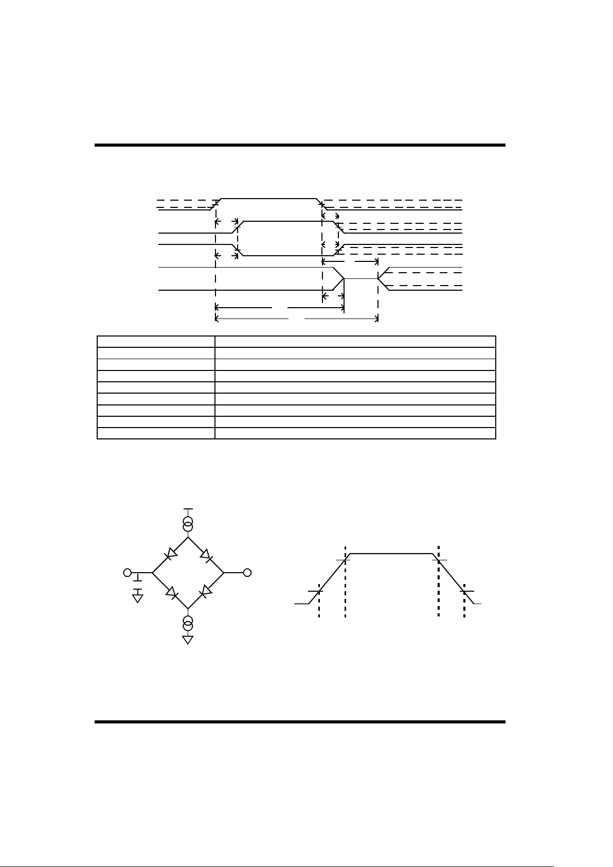
BCRTMP-53
12.0 AC ELECTRICAL CHARACTERISTICS
(OVER RECOMMENDED OPERATING CONDITIONS)
PARAMETERSYMBOL
BUS
OUTPUT
OUT-OF-PHASE
OUTPUT
IN-PHASE
INPUT
Notes:
1. Timing measurements made at (VIH MIN + VIL MAX)/2.
2. Timing measurements made at (VOL MAX + VOH MIN)/2.
3. Based on 50pF load.
4. Unless otherwise noted, all AC electrical characteristics are guaranteed by design or characterization.
1 1
2
2
2
2
V
IH
V
IL
MAX
V
IH
MIN
V
IL
MAX
V
OH
MIN
V
OL
MAX
V
OH
MIN
V
OL
MAX
V
OH
MIN
V
OL
MAX
t
a
t
b
t
c
t
d
t
e
t
f
t
g
t
h
t
a
t
b
t
c
t
d
t
e
t
f
t
g
t
h
INPUT↑ to response↑
INPUT↓ to response↓
INPUT↑ to response↓
INPUT↓ to response↑
INPUT↓ to data valid
INPUT↓ to high Z
INPUT↑ to high Z
INPUT↑ to data valid
90%
Figure 22. AC Test Loads and Input Waveforms
Note:
Input Pulses
10%10%
90%
< 2ns < 2ns
50pF
3V
0V
5V
•
I
REF
(source)
I
REF
(sink)
V
REF
Output Loading
Figure 21. Typical Timing Measurements

BCRTMP-54
MCLKD2
ADDRESS
DATA
AEN
BURST
DMA GRANT RECOGNIZED ON THIS EDGE
THMC1+10
40
SYMBOL PARAMETER MIN MAX UNITS
0
THMC1-10
MCLK-20
ns
ns
ns
ns
ns
ns
0
0
2xMCLK
MCLK
µ
45
4xMCLK
6xMCLK
MCLK+20
3.5 (1.9)
Notes:
0 ns10
s
0 1.9 (0.8)
µ
s
ns0 10
t
SHL1
t
PHL1
1
t
PHL2
t
PZL1
t
HLH2
t
PHL3
t
PW2
t
OOZL1
t
PHL4
t
PHL4
t
SHL1
t
PW2
t
OOZL1
t
PHL4
t
PHL1
t
PHL2
t
PHL3
t
PZL1
t
HLH2
DMACK↓ to DMAR High Impedance
DMAG↓ to DMACK↓ 3
DMAG↓ to TSCTL↓
RWR/RRD↑ to DMACK High Impedance
TSCTL↓ to RWR/RRD↓
DMAG↓ to DMAG↑
DMAR↓ to Burst↑
DMAR↓ to DMAG↓
4,6
TSCTL↓ to ADDRESS valid
DMAR
DMAG
DMACK
TSCTL
MEMCSO
RWR/
RRD
2
1. Guaranteed by test.
2. See figures 24 and 25 for detailed DMA read and write timing.
3 DMAG must be asserted at least 45ns prior to the rising edge of MCLKD2 in order to be recognized for the next MCLKD2 cycle.
If DMAG is not asserted at least 45ns prior to the rising edge of MCLKD2, DMAG is not recognized until the following MCLKD2
cycle.
4. Provided MCLK = 12MHz. Number in parentheses indicates the longest DMAR ↓ to DMAG↓ allowed during worst-case bus switching
conditions in order to meet MIL-STD-1553B RT Response Time. The number not in parentheses applies to all other circumstances.
5 Provided MCLK = 6MHz. Number in parentheses indicates the longest DMAR↓ to DMAG↓ allowed during worst-case bus switching
conditions in order to meet MIL-STD-1553B RT Response Time. The number not in parentheses applies to all other circumstances.
6. The maximum limit for this specification applies only when using DMA Legalization (MD0=1)
MCLK = period of the memory clock cycle.
BURST signal is for multiple-word DMA accesses.
THMC1 is equivalent to the positive phase of MCLK (see figure 24).
DMAR↓ to DMAG↓
5,6
Figure 23. BURST DMA Timing
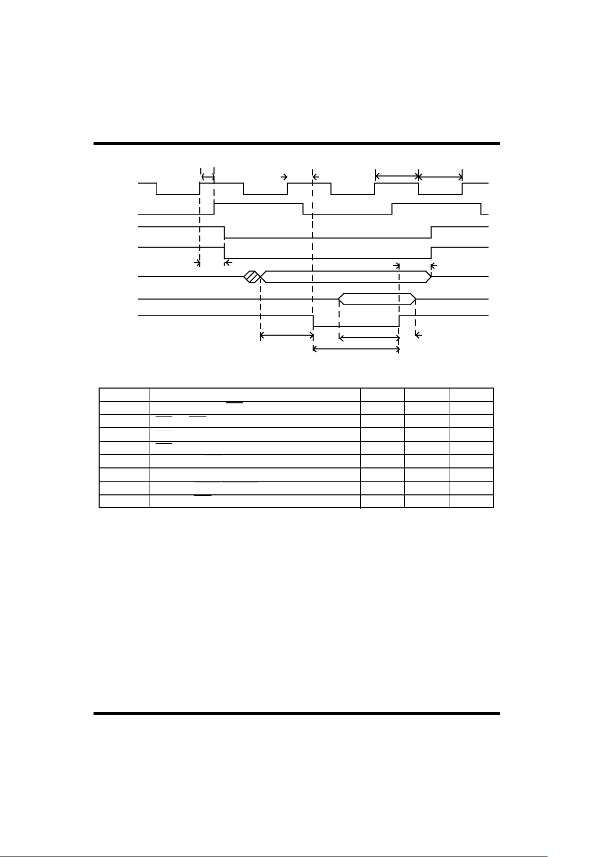
BCRTMP-55
ns
ns
ns
ns
ns
ns
ns
40
-
-
THMC1
MCLK+5
THMC2
0
40
5
THMC1-10
MCLK-5
THMC2-20
UNITSMAXMINPARAMETERSYMBOL
DATA
ADDRESS
MCLKD2
MCLK
THMC1 THMC2
ns600
400
t
SHL1
t
PW1
t
HLZ2
t
HLZ1
t
SLH1
t
PLH2
t
IOHL1
1
t
PLH1
1
t
PLH1
t
IOHL1
t
PLH2
t
SHL1
t
SLH1
t
PW1
t
HLZ1
t
HLZ2
ADDRESS valid to RRD↓ (ADDRESS setup)
RRD↓ to RRD↑
RRD↑ to ADDRESS High Impedance (ADDRESS hold)
RRD↑ to DATA High Impedance (Data hold)
Data valid to RRD↑ (Data setup)
MCLK↑ to MCLKD2↑
MCLK↑ to TSCTL/MEMCSO↓
MCLK↑ to RRD↓
TSCTL
MEMCSO
RRD
Note:
1. Guaranteed by test.
Figure 24. BCRTMP DMA Read Timing (One-Word Read)

BCRTMP-56
ns
ns
ns
ns
ns
ns
ns
400
MCLK-5
THMC1-20
THMC1-20
0
THMC2-20
(ADDRESS hold)
(ADDRESS setup)
UNITSMAXMINPARAMETERSYMBOL
DATA
ADDRESS
MCLKD2
MCLK
THMC2
30
THMC1
THMC1
MCLK+5
THMC1 THMC2
ns
600
1. Guaranteed by test.
Note:
400
t
SHL1
t
PW1
t
HLZ2
t
HLZ1
t
OOZL1
1
t
PLH2
t
IOHL1
1
t
PLH1
1
ADDRESS valid to RWR↓
RWR↓ to DATA valid
RWR↑ to ADDRESS High Impedance
RWR↑ to DATA High Impedance
MCLK↑ to MCLKD2↑
MCLK↑ to TSCTL/MEMCSO↓
MCLK↑ to RWR↓
RWR↓ to RWR↑
(DATA hold)
TSCTL
MEMCSO
RWR
t
PLH1
t
IOHL1
t
PLH2
t
SHL1
t
OOZL1
t
PW1
t
HLZ1
t
HLZ2
Figure 25. BCRTMP DMA Write Timing (One-Word Write)

BCRTMP-57
ns
ns
ns
ns
ns
ns
5
5
-
(DATA hold)
(ADDRESS hold)
UNITSMAXMINPARAMETERSYMBOL
ADDRESS
DATA
(DATA access)
60
80
80
-
-
-
60
50
-
Notes:
1. Guaranteed by test.
2. User must adhere to both t
OOZH1
and t
OOZH2
timing constraints to ensure valid data.
t
HLH2
RD+CS↑ to DATA High Impedance
t
OOZH2
t
OOZH1
1
t
HLH1
t
PW1
t
PW2
ADDRESS valid to DATA valid
RD+CS↓ to DATA Valid
RD+CS↑ to ADDRESS High Impedance
RD+CS↓ to RD+CS↑
RD+CS↑ to RD+CS↓
RD+CS
t
OOZH2
t
OOZH1
t
HLH1
t
HLH2
t
PW1
t
PW2
10
10
60
60
-
-
ns
ns
ns
ns
ns
ns
(DATA hold)
(ADDRESS hold)
(ADDRESS setup)
UNITSMAXMINPARAMETERSYMBOL
ADDRESS
DATA
(DATA setup)
60
80
-
-
-
-
t
HLH2
WR+CS↑ to ADDRESS High Impedance
t
PW2
WR+CS↑ to WR+CS↓
t
HLH1
WR+CS↑ to DATA High Impedance
t
PW1
WR+CS↓ to WR+CS↑
t
SLH1
DATA valid to WR+CS↑
t
SHL1
ADDRESS valid to WR+CS↓
WR+CS
t
SHL1
t
PW1
t
HLH2
t
HLH1
t
SLH1
t
PW2
Figure 26. BCRTMP Register Read Timing
Figure 27. BCRTMP Register Write Timing
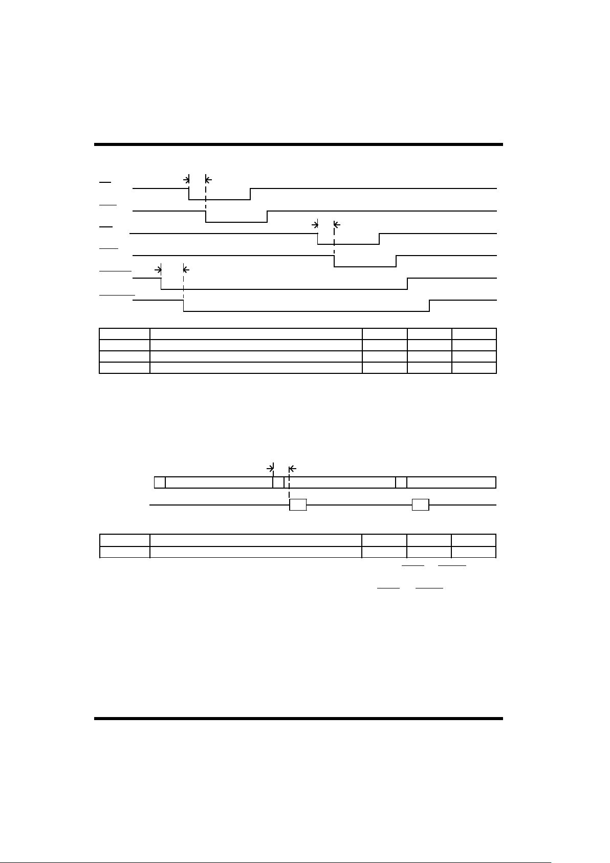
BCRTMP-58
0
SYMBOL PARAMETER MIN MAX UNITS
MANCHESTER
DMA
ACTIVITY
C D D
Data word to DMA activity 4
µ
s
Note:
The pulsewidth = (11ms -t
DMA
-t
PZL1
) where t
DMA
is the time to complete DMA activity (i.e., DMAR↓ to DMACK↑).
t
PZL1
t
PZ
This diagram indicates the relationship between the incoming Manchester code and DMA activity (i.e., DMAR↓ to DMACK↑).
ns
ns
UNITSMAXMINPARAMETERSYMBOL
0
0
0 ns
30
30
30
Note:
1. Guaranteed by test.
t
PLH1
1
RD↓ to RRD↓
t
PLH2
1
t
PLH3
1
WR↓ to RWR↓
MEMCSI↓ to MEMCSO↓
t
PLH1
t
PLH2
t
PLH3
RRD
RD
WR
RWR
MEMCSI
MEMCSO
Figure 28. BCRTMP Dual-Port Interface Timing Delays
Figure 29. DMA Activity(RT Mode)

BCRTMP-59
40
30
10 ns
ns
UNITSMAXMINPARAMETERSYMBOL
0
0
0 ns
MCLK
MCLKD2
Notes:
1. Guaranteed by test.
2. When DMAG is asserted before DMAR, the DMAG signal passes through the BCRTMP as DMAGO.
t
PLH2
1
DMAG↓ to DMAGO↓
t
SHL1
t
PHL1
DMACK↓ to DMAR High Impedance
MCLK↑ to MCLKD2↑
DMAR
DMAG
DMAGO
DMACK
t
PLH2
t
PHL1
t
SHL1
Figure 30. BCRTMP Arbitration when DMAG is Asserted before Arbitration
Figure 27. BCRTMP Register WriteTiming

BCRTMP-60
Figure 31. BCRTMP Legalization Bus Timing
ns
ns
ns
ns
750
200
100
0
LGLCMD
LGL0-10
ns450Legalization Bus Valid to LGLCMD¦
(Setup Time)
SYMBOL
PARAMETER MIN MAX UNITS
(Pulse width)
(Setup Time)
(Hold Time)
LGLEN↓ to LGLEN↑ t
PW1
LGLEN
t
HLH1
t
SLH1
t
HLZ1
t
HLH2
LGLEN↓ to Legalization Bus Valid
LGLCMD↑ to LGLEN↑
LGLEN↑ to LGLCMD Invalid
t
PW1
t
HLH2
t
HLZ1
t
HLH1
t
SLH1

BCRTMP-61
3xMCLK-10 5xMCLK
10xMCLK+1
340
1
8xMCLK+0.5
320
-
ns
ns
UNITSMAXMINPARAMETERSYMBOL
BURST
ns
s
µ
TSCTL↑ to STDINTP/STDINTL↓
t
OOLH1
STDINTP↓ to STDINTP↑ t
PW1
DMACK↓ to RWR↓ t
OOHL1
DMAG↓ to STDINTL↓ t
OOHL2
DMAR
DMAG
DMACK
RWR
RRD
TSCTL
STDINTL
STDINTP
t
OOLH1
t
OOHL1
t
OOHL2
t
PW1
Note:
Address and data bus relationships (not shown) are identical to figure 23.
Figure 32. BCRTMP Interrupt Log List Entry Operation Timing
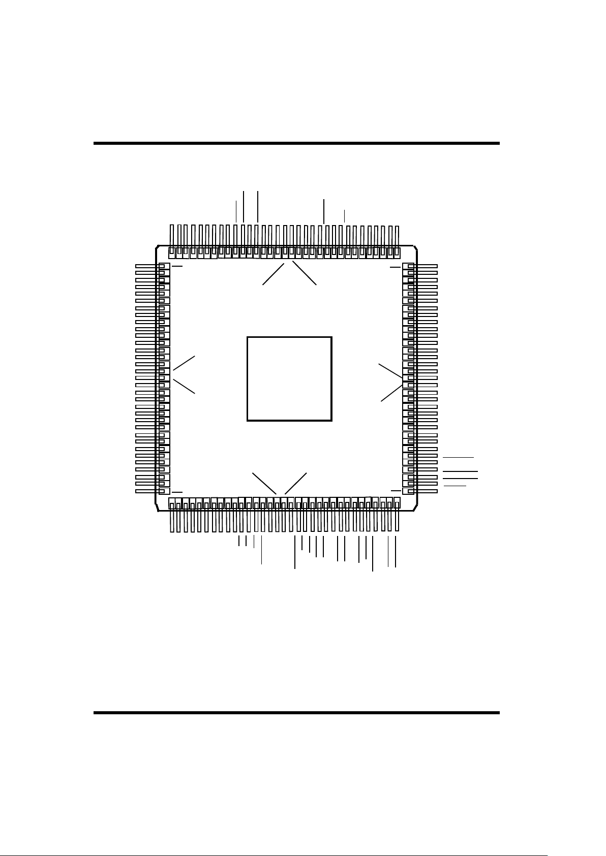
BCRTMP-62
MD2
MD3
MD4
MD5
MD6
MD7
A0
A1
A2
A3
A4
A5
A6
A7
NC
VSS
VDD
NC
A8
A9
A10
A11
A12
A13
A14
A15
RTA0
RTA1
RTA2
RTA3
RTA4
RTPT
RAO
LGL5
LGL4
LGL3
LGL2
LGL0
D15
D14
D13
D12
D11
D10
D9
D8
D7
NC
VDD
VSS
NC
D6
D5
D4
D3
D2
D1
D0
COMSTR
CHA/B
EXTOVR
BCRTSEL
TIMRONB
TIMRONA
HPINT
1
18
116
50
84
LGL1
33
34
132
66 67
99
100
Figure 33a. BCRTMP Flatpack Identification (Top View)
RAZ
TAO
TAZ
RBO
RBZ
TBO
TBZ
MCLK
TEST
AEN
CS
RD
MEMCSI
NC
V
V
NC
MEMCSO
RRD
RWR
DMAR
DMAG
MCLKD2
DMACK
TSCTL
BURST
DMAGO
FBUSY
BUSYACK
ACTIVE
STDINTL
STDINTP
LGL6
LGL7
LGL8
LGL9
LGL10
BRDCASTMCERR
LGLCMD
DOMC
LGLEN
SSYSF
BCRTFNCNCVVNCCLK
ALTWRAP
WRAPF
WRAPEN
MRST
MDO0
MDO1
MDO2
MDO3
MDO4
MDO5
MDO6
LOCK
MD0
MD1
SS
DD
SS
DD
WR
13.0 PACKAGE OUTLINE D RAWINGS

BCRTMP-63
N1 - MDO2
N2 - MDO5
N3 - MD0
N4 - NC
N5 - MD4
N6 - A0
N7 - A3
N8 - V
SS
N9 - V
DD
N10 - A12
N11 - RTA1
N12 - RTA4
N13 - RTPTY
N14 - RAZ
N15 - RBO
A
B
C
D
E
F
G
H
J
K
L
M
N
P
R
1 2 3 4 5 6 7 8 9 10 11 12 13 14 15
Figure 33b. BCRTMP Pingrid Array Pin Identification (Bottom View)
A1 - NC
A2 - LGL2
A3 - D14
A4 - D13
A5 - D12
A6 - D8
A7 - D7
A8 - D6
A9 - D4
A10 - D3
A11 - NC
A12 - CHA/B
A13 - BCRTSEL
A14 - NC
A15 - NC
B1 - NC
B2 - LGL5
B3 - LGL1
B4 - D15
B5 - NC
B6 - D10
B7 - D9
B8 - D5
B9 - D1
B10 - D0
B11 - EXTOVR
B12 - TIMRONA
B13 - HPINT
B14 - STDINTP
B15 - BUSYACK
P1 - MDO6
P2 - MD1
P3 - MD2
P4 - MD3
P5 - MD6
P6 - A1
P7 - A2
P8 - A6
P9 - A10
P10 - A11
P11 - NC
P12 - RTA0
P13 - RTA2
P14 - RAO
P15 - NC
C1 - LGL9
C2 - LGL6
C3 - LGL4
C4 - LGL3
C5 - LGL0
C6 - D11
C7 - V
DD
C8 - V
SS
C9 - D2
C10 - COMSTR
C11 - TIMRONB
C12 - NC
C13 - STDINTL
C14 - FBUSY
C15 - TSCTL
R1 - NC
R2 - NC
R3 - MD5
R4 - MD7
R5 - NC
R6 - A4
R7 - A5
R8 - A7
R9 - A8
R10 - A9
R11 - A13
R12 - A14
R13 - A15
R14 - RTA3
R15 - NC
D1 - BRDCAST
D2 - LGL7
D3 - NC
D4 - NC
D13 - ACTIVE
D14 - BURST
D15 - DMACK
E1 - NC
E2 - LGL10
E3 - LGL8
E13 - DMAGO
E14 - NC
E15 - MCLKD2
F1 - LGLEN
F2 - LGLCMD
F3 - MC
F13 - DMAG
F14 - DMAR
F15 - RRD
G1 - SSYSF
G2 - ERR
G3 - DOMC
G13 - V
DD
G14 - RWR
G15 - MEMCSO
H1 - NC
H2 - BCRTF
H3 - V
DD
H13 - V
SS
H14 - WR
H15 - MEMCSI
J1 - CLK
J2 - WRAPF
J3 - V
SS
J13 - AEN
J14 - TEST
J15 - RD
K1 - ALTWRAP
K2 - WRAPEN
K3 - MRST
K13 - TBZ
K14 - MCLK
K15 - CS
L1 - MDO0
L2 - NC
L3 - MDO4
L13 - TAZ
L14 - RBZ
L15 - NC
M1 - MDO1
M2 - MDO3
M3 - LOCK
M13 - NC
M14 - TAO
M15 - TBO
REGISTRATION

Packaging-1
Package Selection Guide
NOTE:
1. 84LCC package is not available radiation-hardened.
Product
RTI RTMP RTR BCRT BCRTM BCRTMP RTS XCVR
24-pin DIP
(single cavity)
X
36-pin DIP
(dual cavity)
X
68-pin PGA X X
84-pin PGA X X X X
1
144-pin PGA X
84-lead LCC X X X
1
36-lead FP
(dual cavity)
(50-mil ctr)
X
84-lead FP X X
132-lead FP X X

Packaging-2
1
144-Pin Pingrid Array
E
1.565 ± 0.025
-B-
D
1.565 ± 0.025
-A-
0.080 REF.
(2 Places)
0.040 REF.
0.100 REF.
(4 Places)
A
0.130 MAX.
Q
0.050 ± 0.010
A
A
L
0.130 ±0.010
PIN 1 I.D.
(Geometry Optional)
-C-
(Base Plane)
b
0.018 ± 0.002
0.030
0.010
C A B
C
SIDE VIEW
TOP VIEW
0.003 MIN. TYP.
D1/E1
1.400
0.100
TYP.
e
PIN 1 I.D.
(Geometry Optional)
2
R
P
N
M
L
K
J
H
G
F
E
D
1 2 3 4 5 6 7 8 9 10 11 12 13 14 15
Notes:
1. True position applies to pins at base plane (datum C).
2. True position applies at pin tips.
3. All package finishes are per MIL-M-38510.
4. Letter designations are for cross-reference to MIL-M-38510.
BOTTOM VIEW
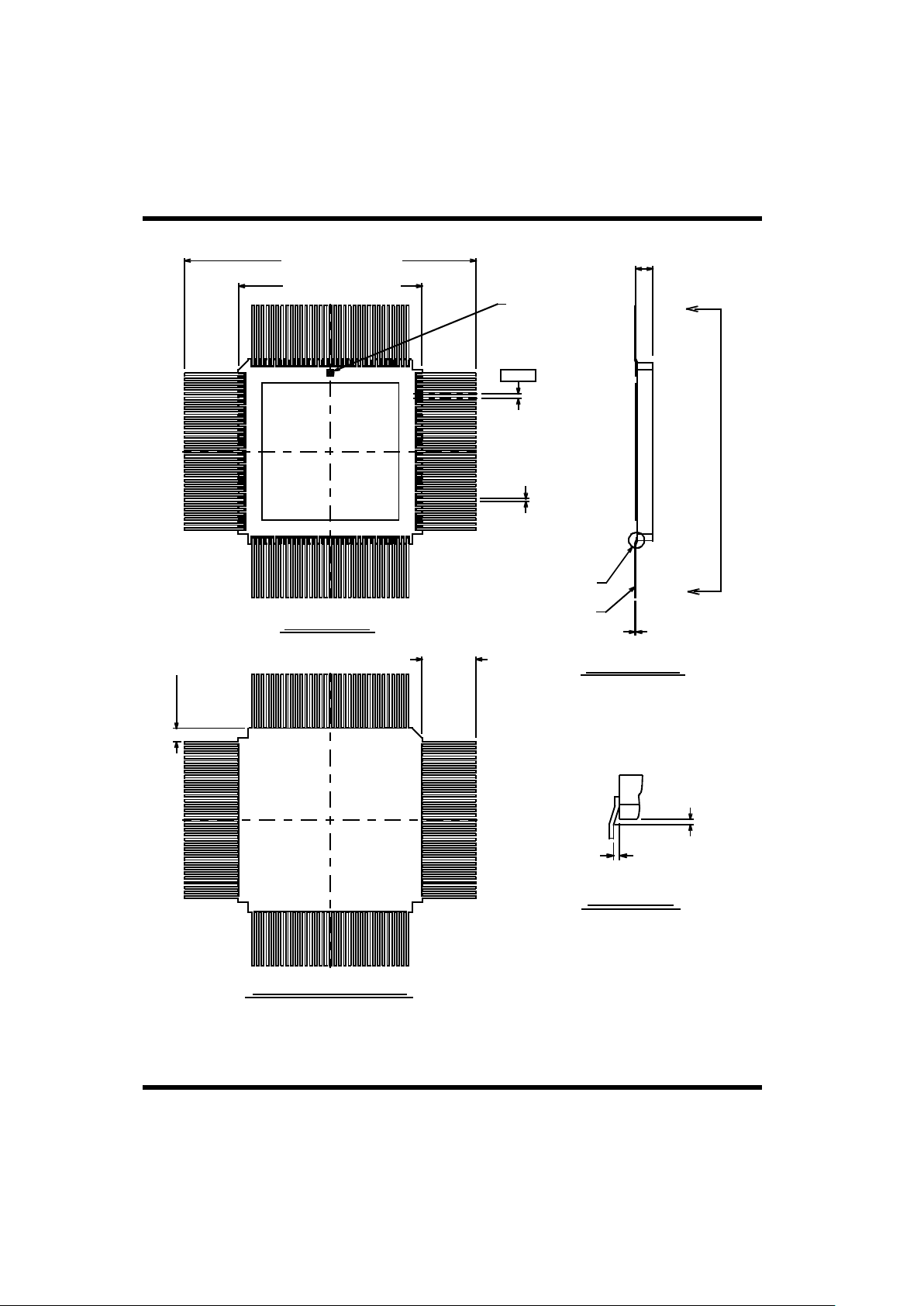
Packaging-3
132-Lead Flatpack (25-MIL Lead Spacing)
SIDE VIEW
TOP VIEW
BOTTOM VIEW A-A
DETAIL A
0.018 MAX. REF.
0.014 MAX. REF.
(At Braze Pads)
L
0.250
MIN.
REF.
LEAD KOVAR
SEE DETAIL A
A
A
C
0.005
+ 0.002
- 0.001
A
0.110
0.006
D1/E1
0.950 ± 0.015 SQ.
D/E
1.525 ± 0.015 SQ.
PIN 1 I.D.
(Geometry
Optional)
e
0.025
Notes:
1. All package finishes are per MIL-M-38510.
2. Letter designations are for cross-reference to MIL-M-38510.
S1
0.005 MIN. TYP.
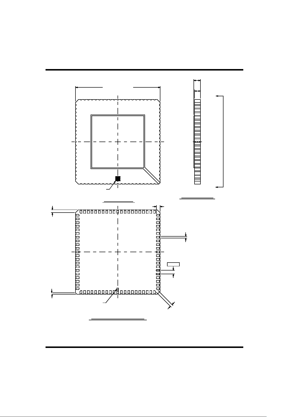
Packaging-4
84-LCC
SIDE VIEW
TOP VIEW
BOTTOM VIEW A-A
Notes:
1. All package finishes are per MIL-M-38510.
2. Letter designations are for cross-reference to MIL-M-38510.
L/L1
0.050 ± 0.005 TYP.
B1
0.025 ± 0.003
e
0.050
e1
0.015 MIN.
PIN 1 I.D.
(Geometry Optional)
J
0.020 X 455 REF.
h
0.040 x 45_
REF. (3 Places)
D/E
1.150 ± 0.015 SQ.
A
0.115 MAX.
A1
0.080 ± 0.008
A
A
PIN 1 I.D.
(Geometry Optional)
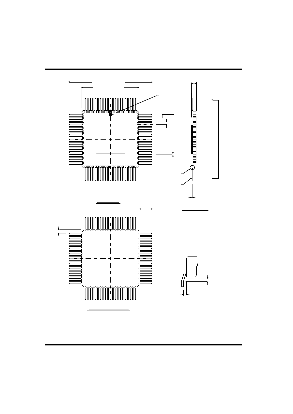
Packaging-5
84-Lead Flatpack (50-MIL Lead Spacing)
SIDE VIEW
TOP VIEW
BOTTOM VIEW A-A
D/E
1.810 ± 0.015 SQ.
Notes:
1. All package finishes are per MIL-M-38510.
2. Letter designations are for cross-reference to MIL-M-38510.
DETAIL A
D1/E1
1.150 ± 0.012 SQ.
A
0.110
0.060
A
A
C
0.007 ± 0.001
LEAD KOVAR
SEE DETAIL A
PIN 1 I.D.
(Geometry
Optional)
b
0.016 ± 0.002
L
0.260
MIN.
REF.
S1
0.005 MIN. TYP.
0.050
e
0.014 MAX.
REF.
(At Braze Pads)
0.018 MAX. REF.

Packaging-6
84-Pin Pingrid Array
SIDE VIEW
TOP VIEW
BOTTOM VIEW A-A
D
1.100 ± 0.020
E
1.100 ± 0.020
-B-
-A-
A
0.130 MAX.
Q
0.050 ± 0.010
L
0.130 ± 0.010
A
A
-C-
(Base Plane)
b
0.018 ± 0.002
PIN 1 I.D.
(Geometry Optional)
1.000
D1/
e
0.100
TYP.
0.003 MIN.
L
K
J
H
G
F
E
D
1 2 3 4 5 6 7 8 9 10 11
Notes:
1. True position applies to pins at base plane (datum C).
2. True position applies at pin tips.
3. All packages finishes are per MIL-M-38510.
4. Letter designations are for cross-reference to MIL-M-38510.
PIN 1 I.D.
(Geometry Optional)
1
0.030
0.010
C A B
C
2

Packaging-7
SIDE VIEW
TOP
BOTTOM VIEW A-A
D
1.100 ± 0.020
PIN 1 I.D.
(Geometry Optional)
L
K
J
H
G
F
E
D
C
B
A
1 2 3 4 5 6 7 8 9 10 11
Notes:
1 True position applies to pins at base plane (datum C).
2 True position applies at pin tips.
3. All packages finishes are per MIL-M-38510.
4. Letter designations are for cross-reference to MIL-M-38510.
PIN 1 I.D.
(Geometry Optional)
D1/E1
1.00
0.003 MIN. TYP.
e
0.100
TYP.
A
0.130 MAX.
Q
0.050 ± 0.010
L
0.130 ± 0.010
A
A
-A-
-B-
E
1.100 ± 0.020
-C-
(Base Plane)
68-Pin Pingrid Array
0.030
0.010 C
A
B
1
2
C
∅
∅
b
0.010 ± 0.002

Packaging-8
D
1.800 ± 0.025
36-Lead Flatpack, Dual Cavity (100-MIL Lead Spacing)
TOP VIEW
END VIEW
E
0.750 ± 0.015
Notes:
1 All package finishes are per MIL-M-38510.
2. It is recommended that package ceramic be mounted to
a heat removal rail located on the printed circuit board.
A thermally conductive material such as MERECO XLN-589 or
equivalent should be used.
3. Letter designations are for cross-reference to MIL-M-38510.
PIN 1 I.D.
(Geometry Optional)
L
0.490
MIN.
b
0.015 ± 0.002
e
0.10
c
0.008
+ 0.002
- 0.001
Q
0.080 ± 0.010
(At Ceramic Body)
A
0.130 MAX.

Packaging-9
36-Lead Flatpack, Dual Cavity (50-MIL Lead Spacing)
TOP
E
0.700 + 0.015
Notes:
1. All package finishes are per MIL-M-38510.
2. It is recommended that package ceramic be mounted to
a heat removal rail located on the printed circuit board.
A thermally conductive material such as MERECO XLN-589
or equivalent should be used.
3. Letter designations are for cross-reference to MIL-M-38510.
c
0.007
+ 0.002
- 0.001
Q
0.070 + 0.010
(At Ceramic Body)
A
0.100 MAX.
END
D
1.000 ± 0.025
b
0.016 + 0.002
e
0.050
PIN 1 I.D
(Geometry Optional)
L
0.330
MIN.

Packaging-10
36-Lead Side-Brazed DIP, Dual Cavity
TOP VIEW
END VIEW
E
0.590 ± 0.012
Notes:
1. All package finishes are per MIL-M-38510.
2. It is recommended that package ceramic be mounted to
a heat removal rail located on the printed circuit board.
A thermally conductive material such as MERECO XLN-589
or equivalent should be used.
3. Letter designations are for cross-reference to MIL-M-38510.
PIN 1 I.D.
(Geometry Optional)
SIDE VIEW
S1
0.005 MIN.
D
1.800 ± 0.025
S2
0.005 MAX.
e
0.100
A
0.155 MAX.
L/L1
0.150 MIN.
C
0.010
+ 0.002
- 0.001
E1
0.600 + 0.010
(At Seating Plane)
b
0.018 ± 0.002

ORDERING INFORMATION
UT1553B BCRTMP Bus Controller Remote Terminal Multi-Protocol: S
Lead Finish:
(A) = Solder
(C) = Gold
(X) = Optional
Case Outline:
(X) = 144 pin PGA
(Y) = 132 pin FP
Class Designator:
(-) = Blank or No field is QML Q
Drawing Number: 8950101
Total Dose:
(-) = None
Federal Stock Class Designator: No options
5962 * * * * *
Notes:
1. Lead finish (A, C, or X) must be specified.
2. If an "X" is specified when ordering, part marking will match the lead finish and will be either "A" (solder) or "C" (gold).
3. 132 FP available with gold lead finish only.
4. For QML Q product, the Q designator is intentionally left blank in the SMD number (e.g. 5962-8950101YC).

UT1553B BCRTMP Bus Controller Remote Terminal Multi-Protocol
Lead Finish:
(A) = Solder
(C) = Gold
(X) = Optional
Screening:
(C) = Military Temperature
(P) = Prototype
Package Type:
(G) = 144 pin PGA
(W) = 132 pin FPv (Gold only)
UTMC Core Part Number
UT1553B
BCRTMP - * * *
Notes:
1. Lead finish (A, C, or X) must be specified.
2. If an "X" is specified when ordering, part marking will match the lead finish and will be either "A" (solder) or "C" (gold).
3. Mil Temp range flow per UTMC’s manufacturing flows document. Devices are tested at -55°C, room temperature, and 125°C. Radiation neither tested
nor guaranteed.
4. Prototpe flow per UTMC’s document manufacturing flows and are tested at 25°C only. Radiation characteristics neither tested nor guaranteed. Lead
finish is GOLD except for LCC
5. 132 FP available with gold lead only.

Packaging-11
E
0.590 ± 0.015
S1
0.005 MIN.
S2
0.005 MAX.
TOP VIEW
PIN 1 I.D.
(Geometry Optional)
D
1.200 ± 0.025
SIDE VIEW
A
0.140 MAX.
L/L1
0.150 MIN.
0.100
e
Notes:
1. All package finishes are per MIL-M-38510.
2. It is recommended that package ceramic be mounted to
a heat removal rail located on the printed circuit board.
A thermally conductive material such as MERECO XLN-589 or
equivalent should be used.
3. Letter designations are for cross-reference to MIL-M-38510.
END VIEW
C
0.010
+ 0.002
- 0.001
E1
0.600 + 0.010
(At Seating Plane)
b
0.018 ± 0.002
24-Lead Side-Brazed DIP, Single Cavity

ORDERING INFORMATION
UT1553B BCRTMP Bus Controller Remote Terminal Multi-Protocol: S
Lead Finish:
(A) = Solder
(C) = Gold
(X) = Optional
Case Outline:
(X) = 144 pin PGA
(Y) = 132 pin FP
Class Designator:
(-) = Blank or No field is QML Q
Drawing Number: 8950101
Total Dose:
(-) = None
Federal Stock Class Designator: No options
5962 * * * * *
Notes:
1. Lead finish (A, C, or X) must be specified.
2. If an "X" is specified when ordering, part marking will match the lead finish and will be either "A" (solder) or "C" (gold).
3. 132 FP available with gold lead finish only.
4. For QML Q product, the Q designator is intentionally left blank in the SMD number (e.g. 5962-8950101YC).

UT1553B BCRTMP Bus Controller Remote Terminal Multi-Protocol
Lead Finish:
(A) = Solder
(C) = Gold
(X) = Optional
Screening:
(C) = Military Temperature
(P) = Prototype
Package Type:
(G) = 144 pin PGA
(W) = 132 pin FPv (Gold only)
UTMC Core Part Number
UT1553B
BCRTMP - * * *
Notes:
1. Lead finish (A, C, or X) must be specified.
2. If an "X" is specified when ordering, part marking will match the lead finish and will be either "A" (solder) or "C" (gold).
3. Mil Temp range flow per UTMC’s manufacturing flows document. Devices are tested at -55°C, room temperature, and 125°C. Radiation neither tested
nor guaranteed.
4. Prototpe flow per UTMC’s document manufacturing flows and are tested at 25°C only. Radiation characteristics neither tested nor guaranteed. Lead
finish is GOLD except for LCC
5. 132 FP available with gold lead only.
 Loading...