


 Loading...
|
UP-308FEW / UP-316FEW |
Table of Contents |
|
Product Overview .................................................................................................................. |
4 |
Package Contents............................................................................................................... |
4 |
Features............................................................................................................................... |
5 |
External Components Description .................................................................................... |
6 |
LED Description.................................................................................................................. |
7 |
Installation.............................................................................................................................. |
8 |
Installation Site Requirements .......................................................................................... |
8 |
Desktop installation............................................................................................................ |
8 |
Rack mounting.................................................................................................................... |
8 |
Power connection............................................................................................................... |
8 |
Connecting to end nodes................................................................................................... |
9 |
Accessing the switch Web management GUI.................................................................... |
10 |
Switch configuration ........................................................................................................... |
11 |
Administrator .................................................................................................................... |
11 |
Authentication Configuration ....................................................................................... |
11 |
System IP Configuration ............................................................................................... |
12 |
System Status ................................................................................................................ |
13 |
Load Default Setting...................................................................................................... |
13 |
Firmware Update............................................................................................................ |
14 |
Reboot device ................................................................................................................ |
14 |
PoE..................................................................................................................................... |
15 |
PoE Status...................................................................................................................... |
15 |
PoE Setting..................................................................................................................... |
16 |
PoE Power Delay............................................................................................................ |
17 |
PoE Scheduling.............................................................................................................. |
18 |
NTP.................................................................................................................................. |
18 |
Port Management.............................................................................................................. |
19 |
Port Configuration ......................................................................................................... |
19 |
Port Mirroring................................................................................................................. |
21 |
Bandwidth Control......................................................................................................... |
22 |
Broadcast Storm Control .............................................................................................. |
23 |
User Manual |
2 |

|
UP-308FEW / UP-316FEW |
VLAN Setting..................................................................................................................... |
24 |
VLAN Mode..................................................................................................................... |
24 |
VLAN Member ................................................................................................................ |
26 |
Multi to 1 Setting............................................................................................................ |
29 |
Per Port Counter ............................................................................................................... |
30 |
QoS Setting ....................................................................................................................... |
31 |
Priority mode.................................................................................................................. |
31 |
Class of Service ............................................................................................................. |
32 |
Security.............................................................................................................................. |
34 |
MAC Address Binding ................................................................................................... |
34 |
TCP/UDP Filter ............................................................................................................... |
35 |
Web Security .................................................................................................................. |
36 |
Spanning Tree ................................................................................................................... |
37 |
STP Bridge Settings ...................................................................................................... |
37 |
STP Port Settings........................................................................................................... |
38 |
Loopback Detection....................................................................................................... |
40 |
Trunking............................................................................................................................. |
41 |
DHCP Relay Agent ............................................................................................................ |
43 |
DHCP Relay Agent ......................................................................................................... |
43 |
Relay Server ................................................................................................................... |
44 |
VLAN MAP Relay Agent................................................................................................. |
44 |
Backup/Recovery.............................................................................................................. |
45 |
Miscellaneous ................................................................................................................... |
46 |
SNMP Settings .................................................................................................................. |
48 |
Logout................................................................................................................................ |
49 |
Specifications ...................................................................................................................... |
50 |
User Manual |
3 |
UP-308FEW / UP-316FEW
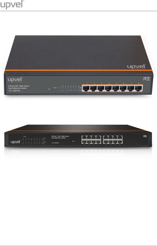
Product Overview
UP-308FEW
UP-316FEW
Package Contents
•8-/16-port PoE+ Switch
•Power cord
•Rack mounting kit: L-brackets (2 pcs) and screws (8 pcs)
•Rubber feet (4 pcs)
•Quick Installation Guide
•Warranty Certificate
Note. If any of the listed items are damaged or missing, please contact your distributor.
User Manual |
4 |

UP-308FEW / UP-316FEW
Features
Upvel PoE+ 802.3at Web Smart Switches UP-308(316)FEW with 8-(16-)port configurations significantly reduce cost of ownership for small and medium size business and professional home PoE installations. Designed to provide easy accessible management and security features, ample power supply, and bandwidth for high-power PoE outdoor Wi-Fi access points, IP-cameras, and VoIP equipment, while complying with latest Green Ethernet Energy savings features.
Management features include conditional monitoring of PoE power supply (available power of ports, power supply delay, priority, and scheduling), Port Mirroring, broadcast storm protection, VLAN (tag / port), QoS, TCP/UDP packet filtering, Spanning Tree, Port Trunking,
DHCP Relay, IGMP Snooping, SNMP, and many more.
All PoE+ ports automatically detect the class of connected Powered Devices and provision up to 30 watts of power on each port as required per 802.3at. The total available power regiment is limited at 140 watts for UP-308FEW and 260 watts for UP-316FEW. Electrical power is transmitted along with data in one single cable allowing you to expand your network where there are no power lines or outlets
For non-PoE devices the power feed is auto-blocked and only data is transmitted. Green Ethernet technology features detect idle ports and cable length on each port and reduces energy consumption by up to 75%.
The total available backbone bandwidth of 1.6 (3.2) Gbps provides necessary throughput while limiting network overload. LED status displays on the front panel facilitate troubleshooting of network connectivity and activity. Rack-mountable 1U steel housing provides proper heat dissipation, and the fanless design guarantees zero operation noise.
Upvel UP-308(316)FEW switches facilitate fast deployment of high-performance secured networks for both PoE and non-PoE devices. Proven performance, advanced control features and high quality workmanship of switching components make it a great choice for expanding office and home networks.
•8 (16) x RJ-45 10/100 Mbps PoE+ ports w/ Auto MDI-X and Auto-negotiation, up to 30 W per port
•Compliant with IEEE 802.3at and IEEE 802.3af Power over Ethernet standards
•140 (260) watts total PoE power budget
•Automatically identifies the PoE class level of Powered Device connected
•Supports two-event classification for IEEE802.3at powered devices
•PoE power supply function management and condition monitoring using Web GUI and SNMP
•Ability to set the maximum available power for each port
•Supports IEEE802.3x flow control for Duplex Mode and backpressure for Half-duplex
Mode
•1.6 (3.2) Gbps switching capacity
•Up to 75% energy saving with Green Ethernet technology
•Rack-Mountable 1U Steel Housing (brackets and screws included)
•Built-in power supply
•Fanless design – zero operation noise
User Manual |
5 |
UP-308FEW / UP-316FEW
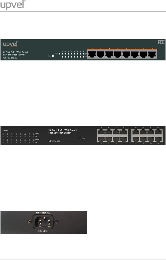
External Components Description
Front panel of UP-308FEW
1~8 |
RJ-45 PoE+ 10/100 Mbps ports |
|
|
Power |
Power LED indicator |
|
|
LNK/ACT 1~8 |
Ethernet connection/activity LEDs of the corresponding ports |
|
|
PoE 1~8 |
PoE-enabled device connection LEDs of the corresponding ports |
|
|
Reset |
Factory Defaults Restore button |
|
|
Front panel of UP-316FEW
1~16 |
RJ-45 PoE+ 10/100 Mbps ports |
|
|
Power |
Power LED indicator |
|
|
LNK/ACT 1~16 |
Ethernet connection/activity LEDs of the corresponding ports |
|
|
PoE 1~16 |
PoE-enabled device connection LEDs of the corresponding ports |
|
|
Reset |
Factory Defaults Restore button |
|
|
Rear panel
The rear panel of the switch contains the AC power connector.
The switch supports 100~240 V AC, 50/60 Hz.
User Manual |
6 |

UP-308FEW / UP-316FEW
LED Description
Indicator |
Color |
Status |
Description |
|
|
|
|
|
|
Power |
Green |
On |
Power on |
|
|
|
|||
Off |
Power off |
|||
|
|
|||
|
|
|
|
|
|
|
On |
Connection is established |
|
LNK/ACT |
Green |
|
|
|
Off |
Connection is not established |
|||
|
|
|
|
|
|
|
Flashing |
Data is being transmitted |
|
|
|
|
|
|
|
|
On |
PoE-enabled device is detected |
|
PoE |
Green |
|
|
|
Flashing |
The power is insufficient for operation of PoE device |
|||
|
|
|
|
|
|
|
Off |
PoE-enabled device is not connected / detected |
|
|
|
|
|
User Manual |
7 |

UP-308FEW / UP-316FEW
Installation
Installation Site Requirements
Ensure that the location where you plan to install the switch meets the following requirements:
•Air temperature and humidity should be within the specified ranges (see technical specifications on pp. 52, 53)
•Vent holes in the switch housing should not be blocked. Make sure that there is enough space around the switch for proper ventilation and heat dissipation. Leave at least 10 cm
(4 inches) of space at the front and rear of the switch.
•The outlet should be close enough for the power cord to reach. The length of the power cord supplied is 150 cm (59 inches).
Desktop installation
Place the switch on a sturdy, level surface that can support at least 5 kg (11 pounds). For better stability, stick four rubber feet to the bottom of the switch near the corners.
Rack mounting
Attach the brackets to the switch using the included screws and then mount the switch on the 19-inch rack using the screws provided with the rack.
Power connection
1.Connect one end of the power cord to the AC power connector on the rear panel of the switch, and then connect the other end of the power cord to an AC power outlet.
2.Check whether the Power LED is ON. When it is steady ON, it indicates the power connection works properly.
User Manual |
8 |
UP-308FEW / UP-316FEW
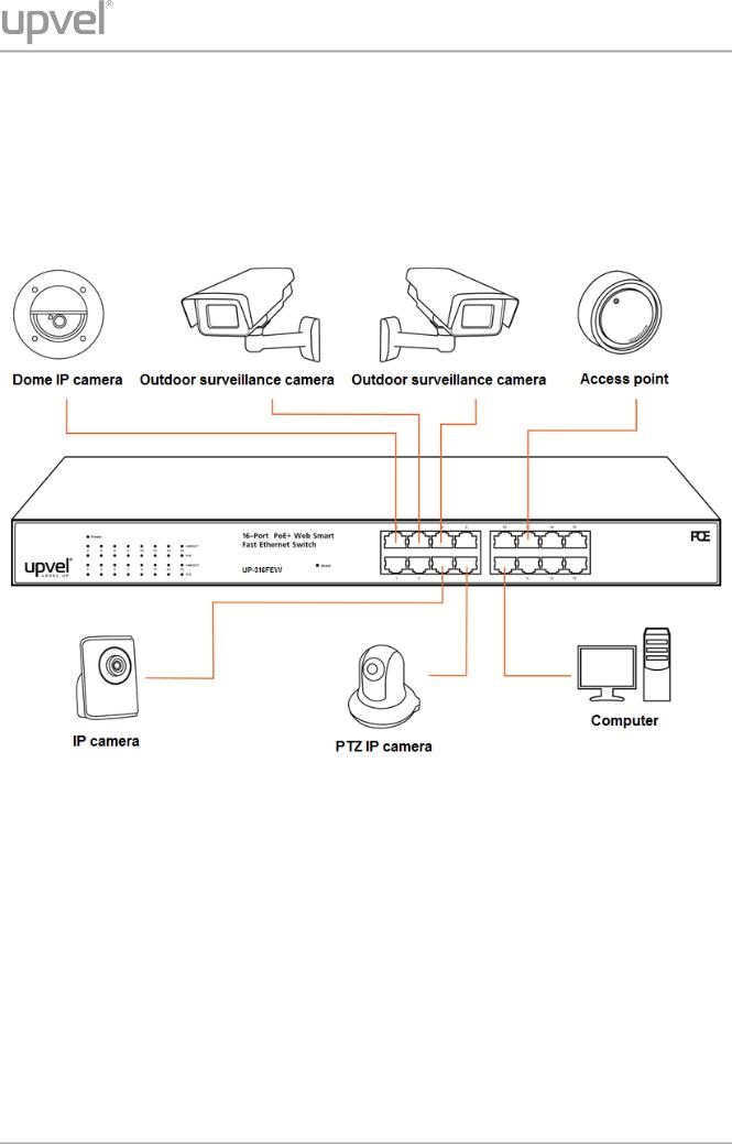
Connecting to end nodes
Use standard Cat.5/5e twisted pair cable (UTP/STP) to connect the switch to end nodes.
Switch ports will automatically adjust to the characteristics (MDI/MDI-X, speed, duplex) of the connected devices.
After connecting all the devices required, you can configure various features of the switch using its Web management interface. Management features include conditional monitoring of the PoE power supply (available power of ports, power supply delay, priority, and scheduling),
Port Mirroring, broadcast storm protection, VLAN (tag / port), QoS, TCP/UDP packet filtering, Spanning Tree, Port Trunking, DHCP Relay, IGMP Snooping, SNMP, and many more.
User Manual |
9 |
UP-308FEW / UP-316FEW
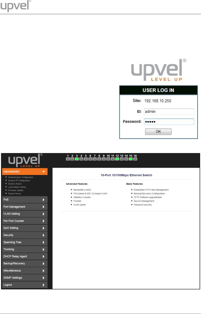
Accessing the switch Web management GUI
1.Connect the switch to the computer, which you will use for configuring the switch.
2.Assign a Static IP address to the computer's network adapter in the subnet of 192.168.10.x (e.g. 192.168.10.100) and a subnet mask of 255.255.255.0
3.Open your web browser, type the IP address of the switch in the address bar, and then press Enter. The default IP address is 192.168.10.250.
4.Enter ID and Password, and then click OK. By default:
ID: admin
Password: admin
Note: ID and Password are case sensitive.
5.The main page of Web management GUI will appear, as shown below.
User Manual |
10 |
UP-308FEW / UP-316FEW
Switch configuration
Administrator
Authentication Configuration
This page allows to change the current username and password that are used to login the switch web management interface.
Enter new Username and/or Password and then click Update to confirm changes. The “Update Successfully” message will appear, as shown below. Click Reboot to reboot the switch and re-login with the new settings.
User Manual |
11 |
UP-308FEW / UP-316FEW
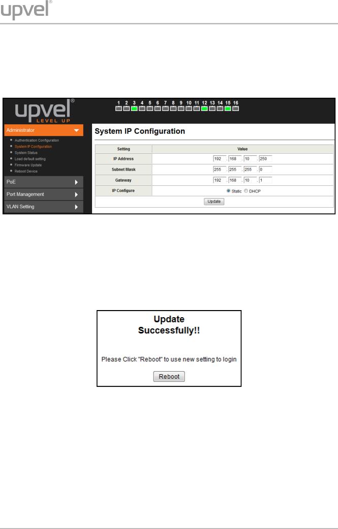
System IP Configuration
This page shows the current IP configuration of the switch including the IP Address, Subnet
Mask, Gateway and IP Configuration type (Static or DHCP).
You can change the IP settings of the switch according to your network configuration. If you choose DHCP in the IP Configure field, the switch will act as DHCP client and will get the IP address from the network DHCP server.
After changing the settings, click Update to confirm changes. The “Update Successfully” message will appear, as shown below. Click Reboot to reboot the switch for the new settings to take effect.
User Manual |
12 |
UP-308FEW / UP-316FEW
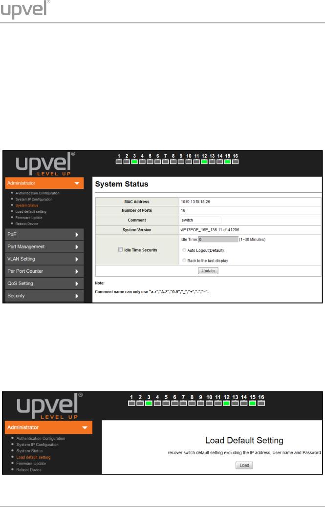
System Status
This page shows the information about the switch: MAC address, firmware version and number of ports.
The Comment field allows to set the switch name so that it could be easily identified in your network.
You can also configure the Idle Time Security function here. If there is no user activity in Web GUI for the specified Idle Time, the system will auto logout or back to the last display.
Click Update for the new settings to take effect.
Load Default Setting
This page allows to restore the factory default settings of the switch. Click Load to execute factory defaults reset procedure. All current settings will be erased, excluding System IP Configuration and Authentication Configuration. Then click Reboot to reboot the switch for the new settings to take effect.
User Manual |
13 |
UP-308FEW / UP-316FEW
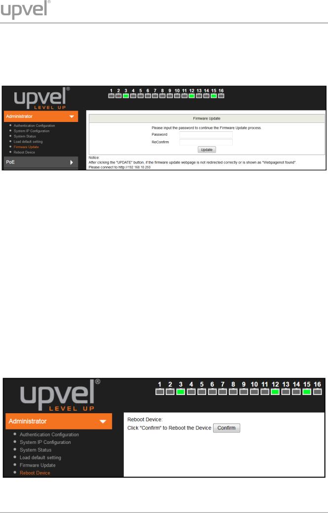
Firmware Update
This page allows to update the firmware of the switch.
To execute the firmware update, you should enter the password in both Password and
Reconfirm fields, and then click Update.
The pop-up warning window will appear for making sure you want to proceed the firmware updating procedure. Confirm to proceed the update.
The switch will erase the current firmware from its flash memory. Note. There is a selfprotection mechanism in the Boot Loader. Even if the power is turned off or the cable link fails during the firmware update procedure, the Boot Loader will restore the code to firmware update page.
Then another page will appear to select the firmware image file for upload. Click Browse to select the file, and then click Update to continue the firmware updating procedure.
Upon completion of the firmware update, click Continue to reboot the switch and re-login.
Reboot device
This page is used to reboot the switch. Click Confirm to reboot.
User Manual |
14 |
UP-308FEW / UP-316FEW
PoE
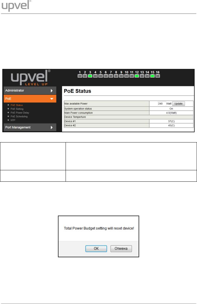
PoE Status
This page contains information about PoE functionality and allows to set the maximum available power of all ports.
System operation status |
Shows the PoE function status (On / Off). |
|
|
|
|
Main Power Consumption |
Indicates the total power consumption of PoE devices |
|
connected to the switch. |
||
|
Device Temperature #1 & #2 Readings of built-in temperature sensors.
Note. Changing the maximum available power requires reboot of the switch. Enter the required value and click Update. In the pop-up message window, click OK to reboot the switch for the new setting to take effect.
User Manual |
15 |

UP-308FEW / UP-316FEW
PoE Setting
This page allows to configure the PoE function for each port.
Status |
Enable/disable PoE for selected ports. |
|
|
|
|
Mode |
Select AF or AT mode according to the PoE standard (802.3af or 802.3at) |
|
supported by the device connected to the port. The port provides up to 15.4 watts |
||
|
in AF mode and up to 30 watts in AT mode. |
|
|
|
|
Priority |
Select the priority (Low, High or Critical) of powering the devices through the |
|
selected ports. |
||
|
||
|
|
|
Power |
The maximum power provided by each of the selected ports. The value specified |
|
Budget |
in this field is multiplied by 0.1, thus for 10 W you should enter 100. |
|
|
|
|
Port No. |
Select the ports to which the settings should be applied. |
|
|
|
All of the settings, excluding Mode, take effect immediately after clicking Update.
Changing the port mode requires reboot of the switch. After clicking Update the following pop-up message appears:
Click OK to reboot the switch for the new settings to take effect.
User Manual |
16 |
Loading...