

Upvel UP-236FEF Quick Installation Manual


UP-236FEF
For instruction in English, see pages 2-8.
Инструкция на русском языке – со страницы 9.
Quick Installation Guide 1
UP-236FEF
Package Contents
• UP-236FEF switch
• Power cord
• 19-inch rack mounting kit: L-brackets (2 pcs) and screws (8 pcs)
• Rubber feet (4 pcs)
• Quick Installation Guide
Note. If any of the listed items are damaged or missing, please contact
your distributor.
External Components Description
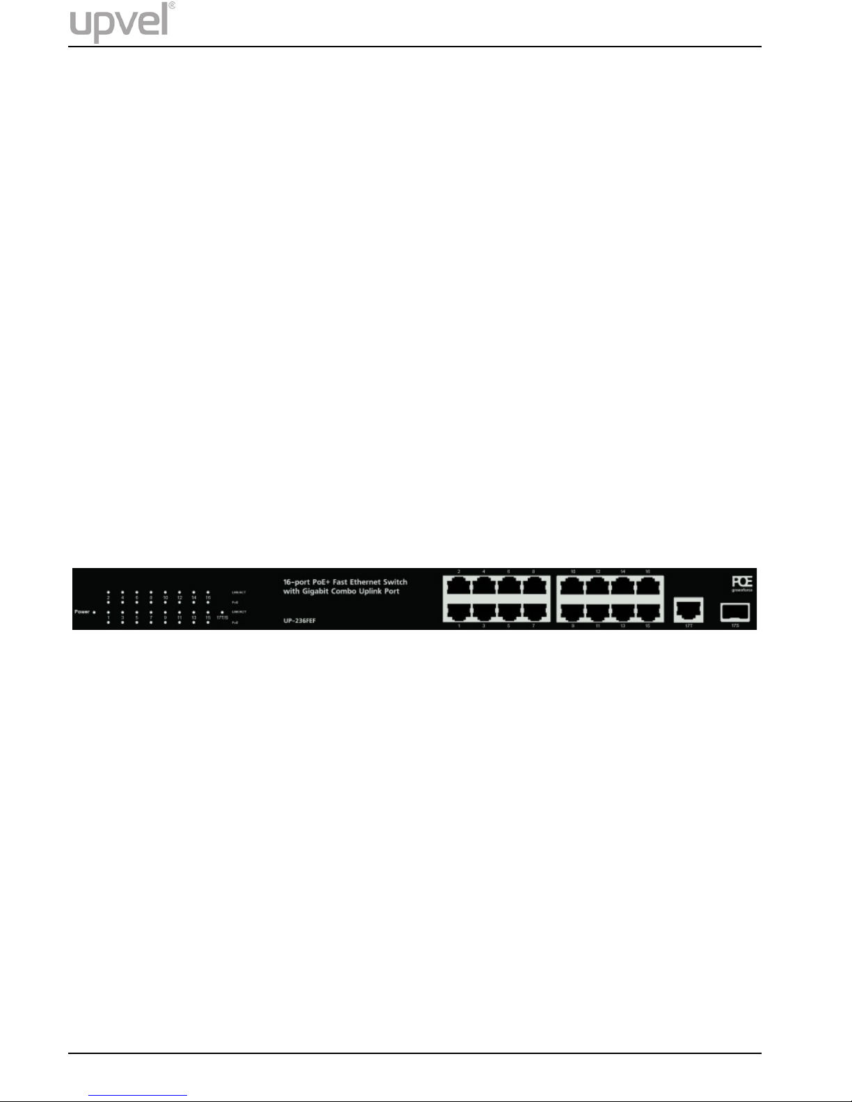
Front panel
1~16: RJ45 100 Mbps PoE+ ports
17T: RJ45 Gigabit uplink port
17S: SFP slot (shared with 17T gigabit uplink port)
Power: Power LED indicator
LNK/ACT 1~16, 17T/S: Connection/activity LEDs of the
corresponding ports
PoE 1~16: PoE-enabled device connection LEDs of the
corresponding ports
2 Quick Installation Guide
UP-236FEF
LED Description
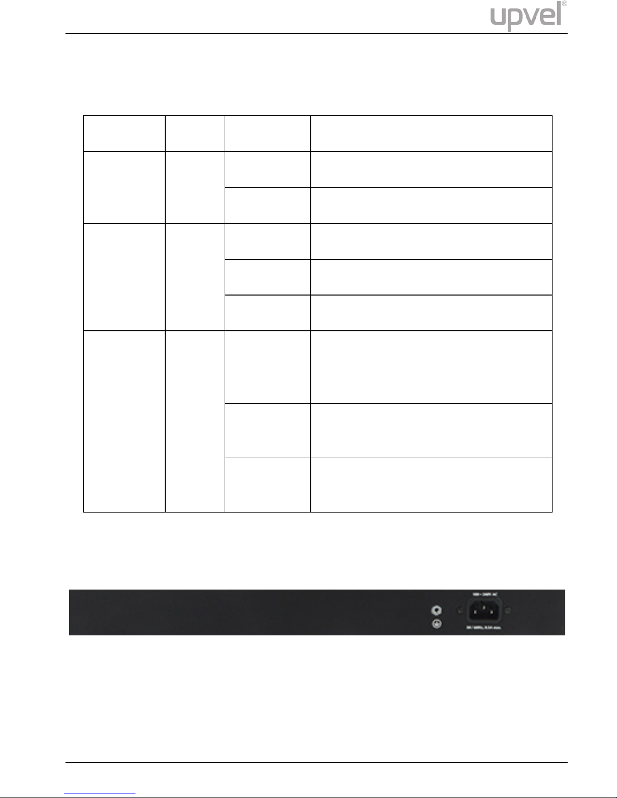
Rear panel
The rear panel of the switch contains the AC power connector and grounding
terminal. The switch supports 100~240 V AC, 50~60 Hz, 2.5 A max.
Indicator
Color
Status
Description
Power Green
On
Power on
Off
Power off
LNK/ACT Green
On
Connection is established
Off
Connection is not established
Flashing
Data is being transmitted
PoE Orange
On
PoE-enabled device is detected,
sufficient power is supplied
successfully
Flashing
The power is insufficient for
operation of PoE device
Off
PoE-enabled device is not
connected/detected
Quick Installation Guide 3

UP-236FEF
Installation
Installation Site Requirements
Ensure that the location where you plan to install the switch meets the
following requirements:
• Air temperature and humidity should be within the specified ranges.
See technical specifications on page 7.
• Vent holes in the switch housing should not be blocked. Make sure
that there is enough space around the switch for proper ventilation
and heat dissipation. Leave at least 10 cm (4 inches) of space at the
front and rear of the switch.
• The outlet should be close enough for the power cord to reach. The
length of the power cord supplied is 150 cm (59 inches).
• Desktop installation: place the switch on a sturdy, level surface
that can support at least 5 kg (11 lbs). For better stability, stick four
rubber feet to the bottom of the switch near the corners.
• Rack mounting: attach the brackets to the switch using the
included screws and then mount the switch on the 19-inch rack using
the screws provided with the rack.
Power connection
1. Connect one end of the power cord to the AC power connector on
the rear panel of the switch, and then connect the other end of the
power cord to an AC power outlet.
2. Check whether the Power LED is ON. When it is steady ON, it
indicates the power connection works properly.
4 Quick Installation Guide
 Loading...