


MECHANICS
MAINTENANCE
MANUAL
SRM60+/0699001 |
ED2 |
0011065
|
SRM60+ |
|
TABLE OF CONTENTS |
DESCRIPTION |
PAGE |
TROUBLE SHOOTING GUIDE ......................................................................………….. 3 REMOVAL OF TOP COVER AND REAR ACCESS PANEL ............................………. 4 MECHANICS MAINTENANCE ......................................................................………….. 4-6 REPAIR INSTRUCTIONS ...........................................................................……………… 7- 12 REPLACEMENT PARTS, LISTS .................................................................…………….. 13 -24 ELECTRICAL CONNECTIONS AND ROTATION .........................................…………. 25 WIRING DIAGRAMS ..................................................................................……………… 26 -28
LIST OF ILLUSTRATIONS
ILLUSTRATION |
|
PAGE |
||
FIGURE |
1 |
OVERALL VIEW OF MIXER ..................................................……... |
2 |
|
FIGURE |
2 |
LUBRICATION INSTRUCTIONS ............................................…….. |
6 |
|
FIGURE |
3 |
GEAR BOX ..............................................................................………. |
13 |
|
FIGURE |
4 |
BEATER HEAD AND VERTICAL SHAFT ASSEMBLY ...........….. |
14 |
|
FIGURE |
5 |
POWER TAKE OFF ASSEMBLY .............................................…….. |
15 |
|
FIGURE |
6 |
INPUT ASSEMBLY .................................................................……… |
16 |
|
FIGURE |
7 |
BOWL LIFT ASSEMBLY ......................................................………. |
17-18 |
|
FIGURE |
8 |
SPEED CONTROL ASSEMBLY ............................................……… |
19 |
-20 |
FIGURE |
9 |
BOWL SUPPORT ASSEMBLY .................................................…… |
21 |
|
FIGURE |
10 |
HOUSING ASSEMBLY .........................................................………. |
22 |
-23 |
FIGURE |
11 |
DRIVE ASSEMBLY .................................................................…….. |
24 |
|
FIGURE |
12A |
WIRING DIAGRAM 208-240 V, 60HZ, 1PH, |
|
|
|
|
220-240V, 50HZ, 1PH, ........…………………………………………. |
26 |
|
FIGURE |
12B |
WIRING DIAGRAM 208-240V, 60HZ, 3PH, |
|
|
|
|
220V, 50HZ, 3PH, 200V, 50/60HZ, 3PH……………………………. |
27 |
|
FIGURE |
12C |
WIRING DIAGRAM 460V, 60HZ, 3PH, 380V, 50HZ, 3PH……….. |
28 |
|
PAGE 1

SRM60+
OVERALL VIEW OF FOOD MIXER
Figure 1
1. |
BEATER SHAFT |
11. |
START BUTTON |
2. |
CHUTE |
12. |
STOP BUTTON |
3. |
SAFETY RING ASSEMBLY |
13. |
BOWL LIFT HANDLE |
4. |
MAGNET |
14. |
REAR ACCESS PANEL |
5. |
NO. 12 HUB |
15. |
BOWL SUPPORT |
6. |
THUMB SCREW |
16. |
BOWL CLAMP |
7. |
UPPER MOUNTING BRACKET |
17. |
BOWL |
8. |
TIMER |
18. |
BOWL RIM |
9. |
SPEED CONTROL LEVER |
19. |
BOWL SUPPORT PIN |
10. |
SPEED INDICATOR LABEL |
20. |
LOWER MOUNTING BRACKET |
Page 2
SRM60+
SRM60+ TROUBLESHOOTING GUIDE
|
TROUBLE |
|
POSSIBLE CAUSE |
|
REMEDY |
|
|
|
|
|
|
1 |
Mixer will not |
1.1 |
Timer not turned on. |
1.1 |
Turn timer on. |
|
operate. |
1.2 |
Burned switch contacts. |
1.2 |
Clean or replace. |
|
|
1.3 |
Electrical service down. |
1.3 |
Check electrical service. |
|
|
|
|
|
Replace fuse or reset circuit |
|
|
|
|
|
breaker as necessary. |
|
|
1.4 |
Motor capacitor defective |
1.4 |
Replace. |
|
|
|
(1PHonly). |
|
|
|
|
1.5 |
Burned out motor. |
1.5 |
Remove, test, repair or |
|
|
|
|
|
replace. |
|
|
1.6 |
Magnetic starter tripped due |
1.6 |
Wait several minutes and |
|
|
|
to overload. |
|
push start button. |
|
|
1.7 |
SAFETY RING not mounted |
1.7 |
Install SAFETY RING. |
|
|
|
and closed. |
|
|
|
|
1.8 |
Bowl not raised. |
1.8 |
Raise bowl completely. |
2. |
Mixer runs but |
2.1 |
Drive belt off of pulley. |
2.1 |
Reinstall drive belt on motor |
|
beater will not |
|
|
|
pulley and adjust mount |
|
turn. |
|
|
|
center distance. |
|
|
2.2 |
Key or pin sheared on bevel |
2.2 |
Locate by step inspection and |
|
|
|
pinion, vertical shaft or beater |
|
replace defective parts. |
|
|
|
shaft. |
|
|
|
|
2.3 |
Shifting with mixer not |
2.3 |
With mixer running, slowly |
|
|
|
running. |
|
move shift lever fully forward |
|
|
|
|
|
then backward in order to |
|
|
|
|
|
re-engage belt. |
|
|
|
|
|
|
3. |
Stalling of |
3.1 |
Mixer bowl is overloaded. |
3.1 |
Readjust contents of bowl per |
|
agitator during |
|
|
|
Capacity Chart. |
|
mixing. |
3.2 |
Speed is set too high for the |
3.2 |
Shift speed lower till action |
|
|
|
mix. |
|
rotates smoothly. |
|
|
3.3 |
Loose belt. |
3.3 |
Readjust pulley center |
|
|
|
|
|
distance to tighten belt. |
|
|
3.4 |
Contamination of belt with |
3.4 |
Clean pulleys and replace |
|
|
|
grease. |
|
belt. |
4. |
Speeds not |
4.1 |
Loose belt. |
4.1 |
Tighten or replace. |
|
changing |
4.2 |
Vari-speed pulley inoperative. |
4.2 |
Remove, clean & lubricate or |
|
properly. |
|
|
|
replace |
5. |
Mixer runs but, |
5.1 |
Bowl overloaded. |
5.1 |
Reduce content of bowl. |
|
keeps cutting out |
5.2 |
Speed set too high for bowl |
5.2 |
Reduce speed |
|
and stops. |
|
contents. |
|
|
|
|
5.3 |
Service voltage is too low or |
5.3 |
Check electrical voltage. |
|
|
|
fluctuating. |
|
|
6. |
Attachments |
6.1 |
Dented bowl. |
6.1 |
remove dent or replace. |
|
contact bottom of |
6.2 |
Bowl height set too high. |
6.2 |
Reset bowl height. |
|
bowl. |
|
|
|
|
7. |
Attachments |
7.1 |
Dented bowl. |
7.1 |
remove dent or replace. |
|
contact side of |
7.2 |
Insufficient clearance between |
7.2 |
readjust bowl height. |
|
bowl. |
|
bottom of bowl and beater. |
|
|
|
|
|
|
|
|
8. |
Excessive noise. |
8.1 |
Gears need to be repacked |
8.1 |
Locate source by inspection |
|
|
|
with grease, or oil level is |
|
and repack with grease or top |
|
|
|
low. |
|
off oil level. |
|
|
8.2 |
Badly worn or frayed drive |
8.2 |
Replace belt. |
|
|
|
belt. |
|
|
|
|
8.3 |
Attachments hitting bowl. |
8.3 |
Inspect for cause. Ref. 6 & 7 |
|
|
8.4 |
Overloaded mixing bowl. |
8.4 |
Readjust contents of bowl per |
|
|
|
|
|
Table of Mixing Capacities. |
Page 3
SRM60+
REMOVAL OF TOP COVER AND REAR ACCESS PANEL
a. The top cover (Fig. 10 [17]) must be removed in order to perform the maintenance operations. It is secured by a spring clip at its front end and a screw at its rearward end. First, DISCONNECT THE ELECTRICAL POWER FOR SAFETY. Then, remove the screw in the rear (Fig. 10 [20]), lift rear of cover, push forward about 3 inches and lift cover off. Re-install in reverse procedure using care to insure that the cover sits squarely and uniformly on the mixer housing.
b.Remove rear access panel (Fig. 10 [27]) by removing eight screws and washers (Fig. 10 [23, 24])
MECHANICS MAINTENANCE
A mechanic should perform the following inspection and maintenance as required depending on severity of use, but at least yearly.
1.CVT BELT DRIVE
a. Start mixer and shift speed control (Fig. 1 [9]) to the slowest speed (Low, 1). Stop mixer.
WARNING: FOR SAFETY, DISCONNECT ELECTRICAL POWER. Place tag or sign on electrical supply warning that MIXER IS BEING WORKED ON; DO NOT TURN ON.
b.Remove rear access panel (Fig. 10 [22]) and top cover (Fig. 10 [17]) as described above.
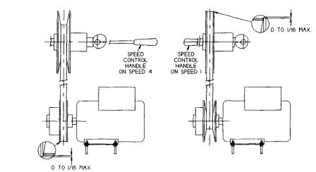
c.Inspect drive belt (Fig. 11 [2]) for proper adjustment. Outer surface of belt should be approximately flush to 1/16" below the outer edges of the input pulley flanges (Fig. 11 [5]) when mixer has been shut off in first speed (see Pg. 5). If drive belt is excessively frayed or has a heavily glazed surface, replace it. However, it is generally the best judgment to leave a drive belt in a machine if it is performing well, even it if shows moderate wear. Inspect gripping surfaces of drive belt for excessively glazed surfaces or contamination by grease or oil.
To replace belt, run mixer in 1st speed. Disconnect electrical supply. Shift machine to 4th speed. Unwrap belt from top pulley. Slide belt between top pulley nose and cam (Fig. 8 [8]). Remove belt from lower pulley.
WARNING: Lower pulley flanges are spring loaded. Keep fingers away while removing belt.
The bowl must be lowered in order for the belt to clear the nose of the lower pulley when removing belt. To install new belt wrap belt around lower pulley. Pull belt into the spring loaded flanges. A pry bar will help separate the flanges.
Continue replacement in reverse order from belt removal. Adjustment of the belt drive will most likely be required.
d. Readjustment of the drive belt, where a slight stretching or normal seating has caused outer surface of the belt to exceed the acceptable limit of flush to 1/16" below the input pulley flanges (see Pg. 5) is as follows:
Loosen kep nuts (Fig. 8 [12]) securing the bracket (Fig. 8 [15]) and holder(Fig. 8 [1]) to the housing. If the belt was riding outside the pulley flanges, tap the speed control assembly lightly towards the rear of the mixer. If the belt was riding more than 1/16" below the pulley flanges, tap the speed
Page 4
SRM60+
control assembly towards the front of the machine (shifting to 2nd second speed will help).
Note: The assembly must remain perpendicular to the mixer housing walls. Failure to do so will result in the binding of the shaft (Fig. 8 [10]) in the bearing (Fig. 8 [21]). Retighten the kep nuts and run mixer in 1st speed and check belt position. Repeat procedure if necessary.
e.Once the upper pulley (Fig. 11 [5]) has been adjusted, the lower pulley must be checked. Start mixer and shift to 4th speed. Turn mixer off and check position of belt. The belt
should be flush to 1/16" below outer edges of the pulley flanges. If adjustment is needed, loosen kep nuts (Fig. 11 [14]) and raise or lower the motor using the kep nuts on the under side of motor. Retighten top kep nuts and run mixer in 4th speed to check new belt position.
Note: The motor must remain level with the mixer base (Fig. 10 [1]). If not, poor shifting and belt life will result.
WARNING: FOR SAFETY, DISCONNECT ELECTRICAL POWER.
DRIVE BELT SETUP
2.MOTOR
Check motor (Fig. 11 [16]) for overheating and excessive noise. If defective, send to a local electrical repair shop.
3.BOWL LIFT ADJUSTMENT
WARNING: FOR SAFETY, DISCONNECT ELECTRICAL POWER.
a.Check adjustment by placing a 60 quart bowl on the lowered bowl support, and place a 60 quart batter beater on the beater shaft (Fig. 1 [1]).
b.Raise bowl support to the upper position.
c.Check clearance between bottom of the bowl and the adjacent underside of the batter beater. Clearance should be 3/16" ± 1/16".
Page 5
SRM60+
d.If adjustment is required, loose jam nut (Fig. 7 [25]) and turn threaded bowl stop rod (Fig.7 [24]) until the desired clearance is obtained, then tighten the jam nut.
4.DRIVE BELT REPLACEMENT (See CVT Belt Drive)
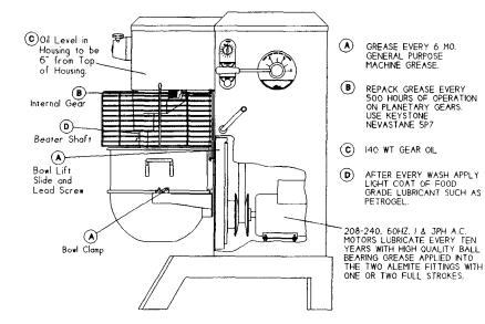
5.LUBRICATION
WARNING: FOR SAFETY, DISCONNECT ELECTRICAL POWER TO THE MIXER.
a.The lubrication instructions are listed in Figure 2.
b.Remove access panel (Fig. 10 [22]), top cover (Fig. 10 [17]) per page 4.
c.In order to service the gearbox, it will be necessary to further remove the gearbox cover (Fig. 3 [2]). A thin blade putty knife will prove helpful in separating the silicone sealant between this cover and the gearbox. Do not bend cover. Thoroughly remove all dried
sealant before applying new sealant when reinstalling the cover. Do not allow dried sealant to enter gearbox. Silicone rubber sealant such as Dow Corning Silastic 732RTV or Permatex Form-A-Gasket are recommended.
WARNING: NEVER WORK ON THE GEARBOX WITH THE MIXER RUNNING.
d.Use care to avoid getting lubricant of any kind on the drive belt and pulleys as this would seriously deteriorate the belt grip and mixer performance.
LUBRICATION INSTRUCTIONS
FIGURE 2
Page 6
SRM60+
REPAIR INSTRUCTIONS
(Including Disassembly, Replacement and Reassembly)
A. GEARBOX (Fig. 3)
GEARBOX REMOVAL:
1.Run mixer and shift to first speed then turn off.
2.WARNING: FOR SAFETY, DISCONNECT ELECTRICAL SUPPLY.
3.Remove set screw (Fig. 3 [16]) and drain oil.
4.Remove rear access panel (Fig. 10 [22]), top cover (Fig. 10 [17]), detailed on page 4.
5.Remove drive belt per instructions (1) in Mechanic's Maintenance.
6.Remove speed control assembly (Fig. 8) SeeSpeed
Control Disassembly.
7.Loosen two allen set screws (Fig. 11 [4]) that secure input pulley (Fig. 11 [5]) and remove pulley completely from input shaft (Fig. 6 [12]).
8.Remove gearbox cover (Fig. 3 [2]). Remove remaining oil from gearbox.
9.WARNING - FOR SAFETY! The gearbox is very heavy, weighing approximately 225 pounds and must, therefore, be supported safely before starting step number (10). It is recommended that a portable hydraulic crane of sufficient capacity be used. A chain may be attached to t he P.T.O. shaft (Fig. 5 [11]) at mid-length. Use care not to rub or scrape the gears.
10.Remove four cap screws (Fig. 3 [11]) securing gearbox housing to mixer housing. Remove gear box assembly and place on work bench.
11.Rotate gear train by hand and inspect for worn or chipped gears, bent shaft, worn bearings and excessive backlash. Backlash measured at gear teeth exceeding 1/32" is
considered excessive. After trouble has been isolated, proceed to disassemble.
GEARBOX DISASSEMBLY:
1.Beater Head (Fig. 4)
a.Remove cap screw (Fig. 4 [21]) and remove beater head assy. If beater head does not drop easily, use the two jacking screws (Fig. 4 [19]) to assist in removal. Do not pry against outer rim of beater head housing (may cause breakage).
b.Remove top retaining ring [9], gear [II], bottom retaining ring [9], key [7], seal [10], retaining ring [9], retaining ring [8], and press shaft [2] (at gear end) from housing [1].
c.Press bearings [4 & 6] along with spacer [5] from housing [1].
Page 7
SRM60+
2.Power Take Off (Fig. 5)
a.Remove three cap screws (Fig. 5 [5]) and washers [6] holding P.T.O. housing [3] to gearbox housing (Fig. 3 [1]).
b.Remove retaining ring [8] from helical gear end of P.T.O. shaft [11]. Remove gear [14] and key [15].
c.Using two cap screws as Jacking screws (Fig. 5 [5]) in the tapped holes of gearbox housing (Fig. 3 [1]), dislodge and remove the P.T.O.
assembly from the gearbox housing.
d.Remove retaining ring [8] and slide bevel gear [13] away from P.T.O. housing [3].
e.Remove internal retaining ring [9], P.T.O. adaptor [2] and press shaft, bearing, and gear assembly from P.T.O. housing [3].
f.Remove four retaining rings [8] and key [15] from P.T.O. shaft [II], and press ball bearings [10] and P.T.O. bevel gear [13] off P.T.O. shaft [11].
g.Remove P.T.O. oil seal [7] from P.T.O. housing [3] and discard.
3.Input (Fig. 6)
a.Remove four cap screws (Fig. 6 [11] from flange of input housing [9].
b.Thread two of the cap screws [11] into the two threaded jacking holes in the flange [9]. Turn these two screws in evenly until the input housing is pushed free of the gear box housing.
c.Remove sleeve [14] and proceed to remove input shaft [12] out of input housing [9] by pressing from opposite the gear end of the shaft.
d.Remove retaining ring [5] at gear end of the shaft, and press off bearing [7].
e.Remove rubber seal [4] from housing or shaft. Seal must be replaced.
f.Remove retaining rings [6] and bearing [7] from housing.
4.Vertical Shaft (Fig. 4)
a.Remove beater head as covered in Gearbox Disassembly (1) a-c. b. Remove P.T.O. assembly as covered in Gearbox Disassembly (2) a-g.
c.Remove key (Fig. 4 [18]) and retaining ring [9] from vertical shaft [13].
d.Drive vertical shaft downward into the gearbox. A brass drift will be necessary to drive shaft completely free from the gear box. Lift bevel gear [12] and key [14] from gear box.
e.Insert drift through top of bearing [15] in gearbox and drive seal [16] out bottom of bore.
Page 8
 Loading...