

Page 1
MRF100B
Page 2
PowerBlaster
TM
WELCOME
1
PowerBlaster
TM
WELCOME
2
Congratulations!
Congratulations on purchasing
Universal Remote Control’s
PowerBlaster
TM
‚ MRF100B!
This changes everything!
When used in combination with
PowerBlaster
TM
, a MasterControl
TM
RF series remote control (RF10,
RF20, RF30) becomes an amazing
remote control powerhouse that
sends multi-directional RF (Radio
Frequency) signals that pass
through walls, doors and floorsboth indoors and outdoors.
PowerBlaster
TM
sets you free!
It enables you to control
Components that are completely
out-of-sight, up to 100’ away. The
PowerBlaster
TM
picks up RF
remote control radio frequency
signals from any direction,
regardless of distance, so the
remote doesn’t need to be pointed
directly at any Component. Just
imagine - no more pointing! Now
you can close your entertainment
center doors, hide your
Components, and still control
them with ease. Control outdoor
speakers on your patio. Control
your Components anywhere!
RF Remotes are ready to go!
One of the best things about this
is - nothing has to be done to
the remotes themselves for this
feature to work. Every time you
press a button on one of the
MasterControl
TM
RF series
remotes, it sends both a standard
IR (Infrared Command) AND an
RF (Radio Frequency) signal.
When you install the PowerBlaster
TM
kit, it will automatically receive radio
signals from RF series remotes and
translate them into the infrared
commands that control your
Components.
Quick Setup DVD Guide makes
installation easy!
The Quick Setup DVD Guide will
assist you in setting up
PowerBlaster
TM
to work with your
RF series remotes by guiding you
through an easy step-by-step
process. This Owner’s Manual is
designed as a companion reference source to the DVD Setup
Guide, should you need to refer
back to a particular section, or
review certain instruction detail
not covered in the DVD. However,
if you are unable to watch the
DVD Guide for some reason,
everything you need to know
about setting up PowerBlaster
TM
is contained in this Manual.
NOTE: PowerBlasterTMis only
compatible with Universal
Remote Control’s MasterControl
TM
RF series remote controls (RF10,
RF20, RF30). RF series remote
control radio signals will not
control Components directly.You
must have a PowerBlaster
TM
to
receive the RF remote radio
signals. Also, Components that
came with "no pointing" radio
remote controls cannot be
operated by an RF series remote
unless the Component can be
switched to standard IR (Infrared
Control) via its internal menus.
Some remote control ceiling fans
are radio only and cannot be
operated by an RF series remote.
POWERBLASTERTMOwner’s Manual
© 2006 Universal Remote Control, Inc.
The information in this manual is copyright protected. No part of this manual may be
copied or reproduced in any form without prior written consent from Universal
Remote Control, Inc. UNIVERSAL REMOTE CONTROL, INC. SHALL NOT BE LIABLE
FOR OPERATIONAL, TECHNICAL OR EDITORIAL ERRORS / OMISSIONS MADE IN
THIS MANUAL. The information in this manual may be subject to change without
prior notice. MASTERCONTROL, PowerBlaster, MacroPower, and SimpleSound are
trademarks of Universal Remote Control, Inc. All other brand or product names are
trademarks or registered trademarks of their respective companies or organizations.
500 Mamaroneck Avenue, Harrison, NY 10528
Phone: (914) 835-4484 Fax: (914) 835-4532
Page 3

PowerBlaster
TM
HOW IT WORKS
3
PowerBlaster
TM
HOW IT WORKS
4
Here’s How PowerBlaster™Works:
1. RF series remote controls (RF10, RF20, RF30) send RF
(Radio Frequency) signals to PowerBlaster™, which is an
RF receiver.
2. PowerBlaster
™
converts RF signals
to IR (Infrared)
commands and sends them out to
components in the same cabinet
space via the built-in front blaster.
3. Self-adhesive “flashers” (included in the PowerBlaster
™
kit) affix to the front panels of your components. The
flashers relay commands to components out of sight of
PowerBlaster’s™front blaster. The flashers plug in to
PowerBlaster’s™rear flasher line output jacks. Each flasher
has a 10’ cable to easily reach components on nearby
shelves.
Page 4
PowerBlaster
TM
PARTS GUIDE
5
PowerBlaster
TM
PARTS GUIDE
6
Parts Guide
Quantity Description
1 PowerBlaster™ Receiver with integrated antenna
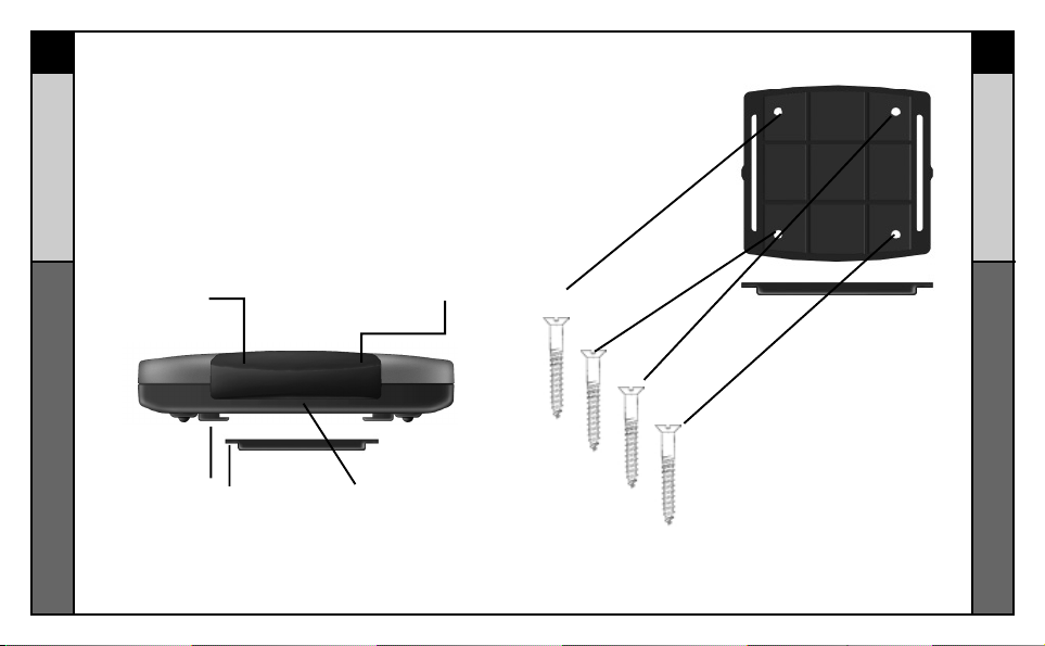
1 Mounting Plate for wall mounting PowerBlaster™
4 Screws for wall mounting the mounting plate
1 9V-300mA Power Supply
6 Flashers with 10 foot plug-in cables.
Red Status LED lights
when PowerBlaster
™
receives an RF signal
from an RF series
remote control.
The Mounting Plate
guides enable
PowerBlaster’s™matching
guide to slide and “snap”
into place for mounting
on the wall.
Front blaster sends
Infrared commands to all
A/V components in the
same cabinet space.
Red Power LED
lights to indicate when
PowerBlaster is
plugged into an active
AC outlet.
Using the four enclosed screws,
you can choose to fix the mounting
plate to a wall or the back of your
component cabinet.
The Mounting Plate
™
Page 5

PowerBlaster
TM
PARTS GUIDE
7
PowerBlaster
TM
PROGRAMMING
8
Six plug-in flashers are supplied
with 10 foot cables and six extra
self-adhesive pads (in case a
flasher has to be repositioned).
Integrated antenna swings
in any direction to optimize
RF reception and range.
Six flasher jacks on the rear of PowerBlaster™ connect
flashers for control of A/V components out-of-sight of the
front blaster.
Included 9V power supply
plugs into the MRF-100
power connector.
t
Program and Test Remote Control First
Don’t connect power to PowerBlaster™ until you have programmed and tested the remote control line of sight.
PowerBlaster™ can interfere with testing and programming.
STEP 1:
Turn ON all of your components.
Audio /Video components some-
imes create RF interference.
Therefore, perform all testing
with all of your components
powered ON (as they will be
when you operate the system).
SETP 2:
Connect the Power Supply.
Connect the 9V power supply to
an active UNSWITCHED AC
outlet. PowerBlaster™ must
always be powered up. The red
Power LED should light up.
STEP 3:
Test Placement of PowerBlaster™.
PowerBlaster™ should be
placed so that the STATUS LED
only lights up when a button is
pressed on an RF series remote
control. It should go out as soon
as the button is released. If
there is any flickering, move
PowerBlaster™ farther away
from the A/V components.
STEP 4:
Orient the Antenna for Optimum
Range. If you need to extend the
range of the remote, try adjusting
the angle of PowerBlaster’s™
receiving antenna via it’s pivoting
ball mount.
STEP 5:
Mount PowerBlaster
PowerBlaster™ may be
concealed and mounted to the
rear wall or back of the system
cabinet. The mounting plate
slides apart from the receiver,
mounts to the wall, then the
receiver can slide back into
place.
™.
Page 6

PowerBlaster
TM
PROGRAMMING
9
PowerBlaster
TM
WARRANTY
10
Page 7

MRF100B
MRF100B
Page 8

PowerBlaster
TM
BIENVENIDA
11
PowerBlaster
TM
BIENVENIDA
12
Page 9

PowerBlaster
TM
CÓMO FUNCIONA
13
PowerBlaster
TM
CÓMO FUNCIONA
14
Page 10

PowerBlaster
TM
GUÍA DE PIEZAS
15
PowerBlaster
TM
GUÍA DE PIEZAS
16
Page 11

PowerBlaster
TM
GUÍA DE PIEZAS
17
PowerBlaster
TM
PROGRAMACIÓN
18
Page 12

PowerBlaster
TM
GUÍA DE PIEZAS
19
PowerBlaster
TM
GARANTÍA
20
Page 13

MRF100B
 Loading...