


MRF-350
MRF-350 Installation Manual
Optimizing Narrow Band Reception with
the RFX-250 and MSC System Remotes
COMP L ETE
™
UniversalRemoteControl
®
CONTROL
COMP L ETE

MRF-350 Installation Manual ©2006 Universal Remote Control, Inc.
The information in this manual is copyright protected. No part of this manual may be copied
or reproduced in any form without prior written consent from Universal Remote Control, Inc.
UNIVERSAL REMOTE CONTROL, INC. SHALL NOT BE LIABLE FOR OPERATIONAL,TECHNICAL OR EDITORIAL ERRORS/OMISSIONS MADE IN THIS MANUAL.
The information in this manual may be subject to change without prior notice.
Complete Control, Aurora, Genesis and Medius are registered trademarks of Universal Remote
Control, Inc.
All other brand or product names are trademarks or registered trademarks of their respective
companies or organizations.
500 Mamaroneck Avenue, Harrison, NY 10528
Phone: (914) 835-4484 Fax: (914) 835-4532

TABLE OF CONTENTS
Introduction 1
Features and Benefits 2
Parts Guide 2
Optimizing Range and Reliability 3
Connecting IR and Setting Output Levels 6
Front Blaster Overload 7
Disabling the Front Blaster - Step by Step via PC 7
Controlling An Array of Identical Components or Zones 8
Identical Components/Zones - Step by Step via PC 8
Programming For Multiple Equipment Locations 11
Frequently Asked Questions 12
Warranty 12
Specifications 12
Page 1
MRF-350 BASE STATION
Introduction
The MRF-350 base station is an “addressable” base station like the MRF-300.
RF Addressing gives you the ability to control as many as 90 identical components throughout a house. However, the MRF-350 is equipped with the
Narrow Band RF reception, so is only compatible with MSC System remotes.
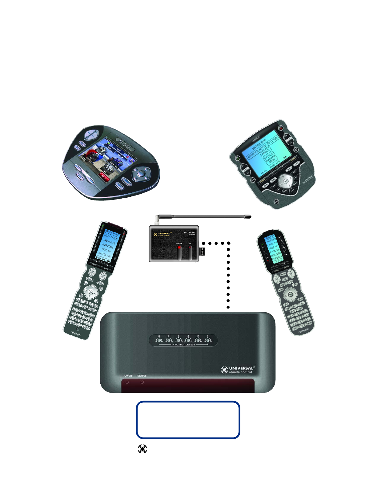
4. Self-adhesive “Flashers” affix to the
Infrared sensors on the front panels of your
client’s components. The Flashers relay
commands to components out of sight of
the MRF-350’s Front Blaster. The flashers
plug in to the MRF-350’s rear flasher line
outputs via their 10 foot cables. Uniquely, the
MRF-350 can also connect to rear panel IR
Inputs via its adjustable IR Line Outputs.
3.The MRF-350’s built-in Front Blaster sends commands to
components in the same cabinet space as the MRF-350.
1. MSC System remote controls send
radio waves in every direction, so
your client enjoys “No More Pointing”
operation!
2.The RFX-250 RF Sensor can be freely positioned out of way of
the interference the A/V components create, connecting to the
MRF-350 via a 10’ cable (which can be extended).
NOTE: The RFX-250 is ONLY compatible with MSC System remotes: the current
versions of the MX-3000, MX-950, MX-900 and the TX-1000 remote controls.The
RFX-250 is NOT compatible with MX-3000 remote controls manufactured before
April 1, 2005.
You can identify the build date of an MX-3000 by looking at the serial number.The
first 6 digits indicate the build date. If the serial number appears as 122905
014054, the first 6 digits indicate that the remote was built on December 29, 2005.

Page 2
MRF-350 BASE STATION
Features and Benefits
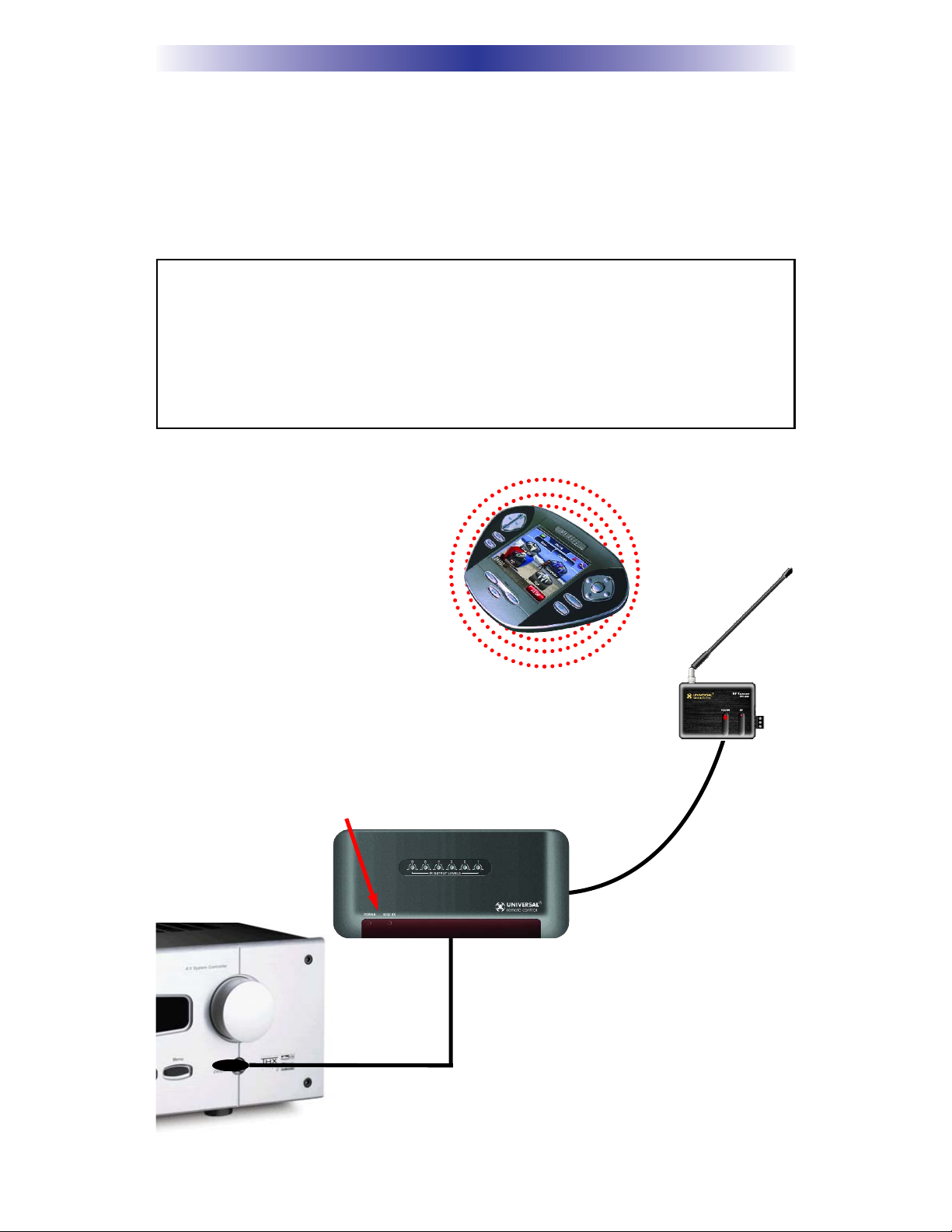
Interference Rejection and Extended RF Range via RFX-250
The MRF-350 receives RF (radio frequency) signals via the RFX-250 RF Sensor.
The RFX-250 displays RF interference via a bright red LED, which flickers when
interference is present. Simply relocate the RFX-250 out of the interference.
Expand Range by Adding RFX-250 RF Sensors in Remote Areas
The MRF-350 can power up to three RFX-250 RF Sensors connected in parallel
to the RF Input connector.
Variable IR Output Matches Rear Panel IR Inputs
The MRF-350 is equipped with adjustable IR line outputs, each output can be individually matched to rear panel IR inputs on any component that is designed to be
operated by a standard IR repeater.The outputs utilize a 3.5mm jack.
Up To Fifteen Equipment Locations With Identical Components
Each MSC System remote is “addressable.” They can be programmed to specifically control components in a particular room by installing a base station at each
location. In operation it’s simple: when you select a device located in the Den,
the MX series remote only sends commands to the Den. When you select a
device located in the Family Room, the MX-3000 only sends commands to it.
A Single MRF-350 Can Control an Array of Identical Components
or Identical Zones of a Multi Zone Preamp/Matrix Switcher
Each MRF-350 has six “addressable” IR Line Outputs. For example, you can control up to six identical TV’s with one MRF-350 or route volume commands for a
specific zone to a particular zone IR input on a multi-zone preamp. If you have
more than six identical components or zones, up to 15 additional MRF-350s can
be installed to control them (thus allowing up to 90 identical components or
zones in one house).
IR Input for Keypads or IR Repeater Systems
The MRF-350 rear panel IR input will relay IR Data from IR repeaters or MultiZone Keypads to all IR line outputs (does not support IR routing).The 5V, 100
milliamp output will directly power some brands and models of keypad directly.
Parts Guide
The MRF-350 RF Base Station includes:
1 - RFX-250 RF Sensor with integrated
antenna
1 - Mounting plate for RFX-250
1 - MRF-350 Base Station
1 - Mounting Plate for wall mounting the
MRF-350
8 - Screws for wall mounting the two
mounting plates
1 - 9V-300mA Power Supply
6 - Visible Flashers with 10 foot plug in cables.
6 - Extra self adhesive pads for Emitters
1 - 12’ Connecting Cable
1 - Adjustment Tool (Screwdriver for RF ID
and IR level adjustment)
2 - Depluggable screw connectors for RF
connections when extending wires.
 Loading...