

Page 1

MRF100B
PowerBlaster
OWNER’S
MANUAL
No More Pointing..
changing the way a
remote control works!
™
500 Mamaroneck Avenue
Harrison, NY 10528
Phone: 1-914-835-4484
FAX: 1-914-835-4532
www.universalremote.com
OWNER’S MANUAL
No More Pointing..
changing the way a
remote control works!
Universal Remote Control
MRF100B
PowerBlaster
™
Page 2
1
™
Congratulations!
Congratulations on purchasing
Universal Remote Control’s
PowerBlaster
PowerBlaster
This changes everything!
When used in combination with
PowerBlaster
RF series remote control (RF10,
RF20, RF30) becomes an amazing
remote control powerhouse that
sends multi-directional RF (Radio
Frequency) signals that pass
through walls, doors and floors –
both indoors and outdoors.
PowerBlaster
It enables you to control
Components that are completely
out-of-sight, up to 100’ away. The
PowerBlaster
remote control radio frequency
signals from any direction,
regardless of distance, so the
remote doesn’t need to be pointed
directly at any Component. Just
imagine – no more pointing! Now
you can close your entertainment
WELCOME
™
MRF100B!
™
, a MasterControl
™
sets you free!
™
picks up RF
center doors, hide your
Components, and still control
them with ease. Control outdoor
speakers on your patio. Control
your Components anywhere!
RF Remotes are ready to go!
One of the best things about this
™
is — nothing has to be done to
the remotes themselves for this
feature to work. Every time you
press a button on one of the
MasterControl
remotes, it sends both a standard
™
RF series
IR (Infrared Command) AND an
RF (Radio Frequency) signal.
When you install the
PowerBlaster
ically receive radio signals from
™
kit, it will automat-
RF series remotes and translate
them into the infrared commands
that control your Components.
Quick Setup DVD Guide makes
installation easy!
The Quick Setup DVD Guide will
assist you in setting up
PowerBlaster
RF series remotes by guiding you
™
to work with your
through an easy step-by-step
process. This Owner’s Manual is
designed as a companion reference source to the DVD Setup
Guide, should you need to refer
back to a particular section, or
review certain instruction detail
not covered in the DVD. However,
if you are unable to watch the
DVD Guide for some reason,
everything you need to know
about setting up PowerBlaster
contained in this Manual.
500 Mamaroneck Avenue, Harrison, NY 10528
Phone: (914) 835-4484 Fax: (914) 835-4532
POWERBLASTER™ Owner’s Manual
The information in this manual is copyright protected. No part of this manual may be
copied or reproduced in any form without prior written consent from Universal
Remote Control, Inc. UNIVERSAL REMOTE CONTROL, INC. SHALL NOT BE LIABLE
FOR OPERATIONAL, TECHNICAL OR EDITORIAL ERRORS / OMISSIONS MADE IN
THIS MANUAL. The information in this manual may be subject to change without
prior notice. MASTERCONTROL, PowerBlaster, MacroPower, and SimpleSound are
trademarks of Universal Remote Control, Inc. All other brand or product names are
trademarks or registered trademarks of their respective companies or organizations.
© 2006 Universal Remote Control, Inc.
NOTE: PowerBlaster™is only
compatible with Universal
Remote Control’s MasterControl™
RF series remote controls (RF10,
RF20, RF30). RF series remote
control radio signals will not
control Components directly. You
must have a PowerBlaster™ to
receive the RF remote radio
signals. Also, Components that
came with "no pointing" radio
remote controls cannot be
operated by an RF series remote
™
is
unless the Component can be
switched to standard IR (Infrared
Control) via its internal menus.
Some remote control ceiling fans
are radio only and cannot be
operated by an RF series remote.
2
PowerBlaster
™
WELCOME
Page 3
3
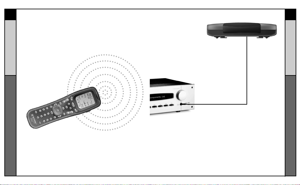
Here’s How PowerBlaster™Works:
™
1. RF series remote controls (RF10, RF20, RF30) send RF
(Radio Frequency) signals to PowerBlaster™, which is an
RF receiver.
PowerBlaster
2. PowerBlaster
converts RF signals
to IR (Infrared)
commands and sends them out to
components in the same cabinet
space via the built-in front blaster.
™
4
PowerBlaster
™
HOW IT WORKS
HOW IT WORKS
3. Self-adhesive “flashers” (included in the PowerBlaster
kit) affix to the front panels of your components. The
flashers relay commands to components out of sight of
PowerBlaster’s™front blaster. The flashers plug in to
PowerBlaster’s™rear flasher line output jacks. Each flasher
has a 10’ cable to easily reach components on nearby
shelves.
™
Page 4
5
Parts Guide
™
Quantity Description
1 PowerBlaster™ Receiver with integrated antenna
1 Mounting Plate for wall mounting PowerBlaster™
4 Screws for wall mounting the mounting plate
1 9V-300mA Power Supply
PowerBlaster
6 Flashers with 10 foot plug-in cables.
Red Power LED
lights to indicate when
PowerBlaster is
plugged into an active
AC outlet.
™
Red Status LED lights
when PowerBlaster
receives an RF signal
from an RF series
remote control.
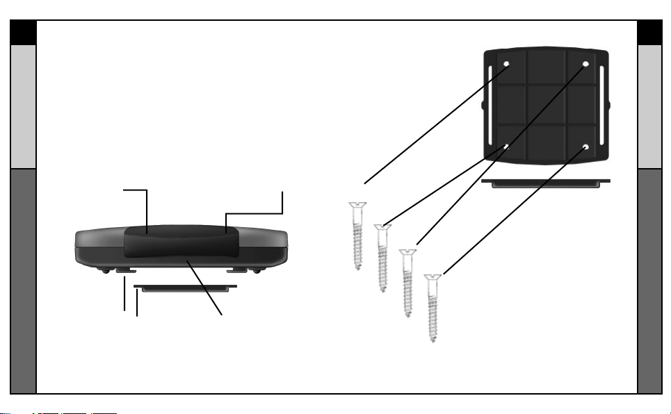
6
The Mounting Plate
™
PowerBlaster
™
PARTS GUIDE
The Mounting Plate
guides enable
PowerBlaster’s™matching
guide to slide and “snap”
into place for mounting
on the wall.
PARTS GUIDE
Front blaster sends
Infrared commands to all
A/V components in the
same cabinet space.
Using the four enclosed screws,
you can choose to fix the mounting
plate to a wall or the back of your
component cabinet.
Page 5
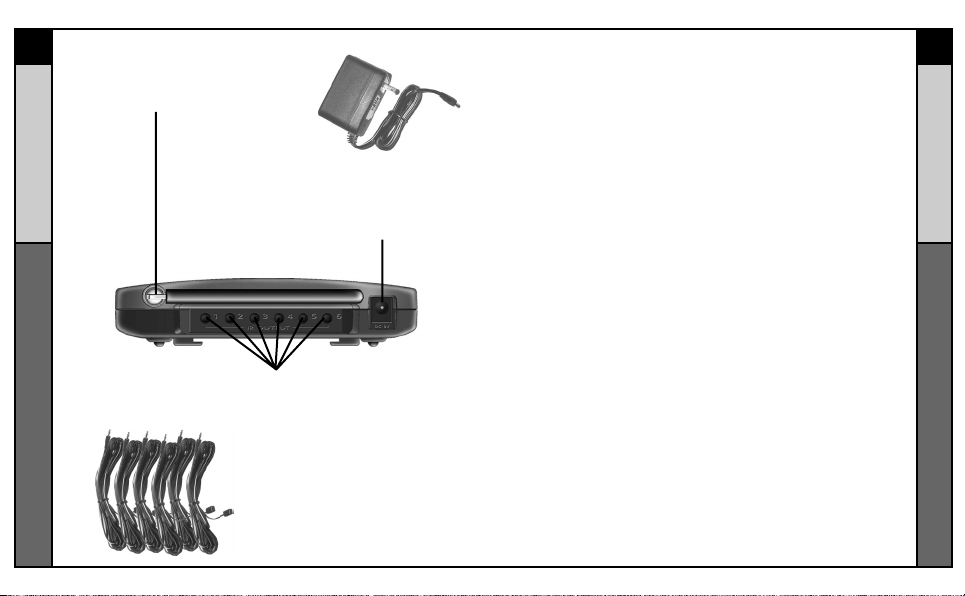
Integrated antenna swings
™
in any direction to optimize
RF reception and range.
PowerBlaster
Included 9V power supply
plugs into the MRF-100
power connector.
Six flasher jacks on the rear of PowerBlaster™ connect
flashers for control of A/V components out-of-sight of the
front blaster.
Six plug-in flashers are supplied
with 10 foot cables and six extra
self-adhesive pads (in case a
flasher has to be repositioned).
PARTS GUIDE
Program and Test Remote Control First
Don’t connect power to PowerBlaster™until you have programmed and tested the remote control line of sight.
PowerBlaster™ can interfere with testing and programming.
STEP 1:
Turn ON all of your components.
Audio /Video components sometimes create RF interference.
Therefore, perform all testing
with all of your components
powered ON (as they will be
when you operate the system).
SETP 2:
Connect the Power Supply.
Connect the 9V power supply to
an active UNSWITCHED AC
outlet. PowerBlaster™ must
always be powered up. The red
Power LED should light up.
STEP 3:
Test Placement of PowerBlaster™.
PowerBlaster™ should be
placed so that the STATUS LED
only lights up when a button is
pressed on an RF series remote
control. It should go out as soon
as the button is released. If there
is any flickering, move
PowerBlaster™ farther away
from the A/V components.
STEP 4:
Orient the Antenna for Optimum
Range. If you need to extend the
range of the remote, try adjusting
the angle of PowerBlaster’s
receiving antenna via it’s pivoting
ball mount.
STEP 5:
Mount PowerBlaster™.
PowerBlaster
concealed and mounted to the
rear wall or back of the system
cabinet. The mounting plate
slides apart from the receiver,
mounts to the wall, then the
receiver can slide back into
place.
™
may be
87
PowerBlaster
™
PROGRAMMING
™
Page 6
9
STEP 6
™
Test Operation Without Flashers.
With the remote controls
line-of-sight output blocked by
your hand, a book or a pillow;
test the control of your
components using just the front
PowerBlaster
blaster. In most cabinets, the
PowerBlaster’s
control any A/V components in
the same cabinet space by
reflections from the cabinet
walls and doors. Make sure that
the components operate with the
cabinet doors closed or open.
If a component is placed too far
away from the front blaster, you
will need to utilize the included
flashers plugged into
PowerBlaster’s
jacks.
If you have problems with
components that are close to
the front blaster, try repositioning
PowerBlaster
™
front blaster will
™
rear flasher
™
farther away.
PROGRAMMING
STEP 7:
Connect Flashers to Out-of-Sight
A/V Components.
Note:Test the operation
BEFORE sticking the flasher
in place.
Use a flashlight to identify the
correct location of the
component’s IR sensor, then try
a few commands while moving
the flasher around the face plate
of the component. The most
reliable operation typically
occurs a half inch or so away
from the IR sensor. Once you
have found the spot that gives
the most reliable operation, peel
off the protective backing of the
self-adhesive tape on the
included flashers and stick them
in place.
Note: Always replace the
self-adhesive tabs if you have
to reposition a flasher. Six
extra self-adhesive tabs are
supplied for this purpose.
Warranty
PowerBlaster™is covered against any manufacturers defects or
workmanship for a period of one year from the date of purchase if
purchased from an authorized Universal Remote Control dealer. Units
purchased from online auction sites or other unauthorized resellers
have no warranty. This warranty does not cover the following items:
- Damage from misuse, neglect, or acts of nature.
- Products that have been modified or incorporated into
other products.
- Products purchased more than 12 months ago.
- Units purchased from unauthorized dealers or companies.
Specifications
Power Supply: 9V 300mA
IR Flasher Line Outputs: 2.5mm Mono Mini Jack
RF Frequency: 418MHz
Who can I call for more answers?
The Universal Remote Control Technical Support and Customer
Service staff are ready to answer any questions you might have.
Call us at 1-914-835-4484
Monday - Friday, 9AM to 6PM (EST)
10
PowerBlaster
™
WARRANTY
Page 7
Page 8
1 2
The RF20 Remote
WELCOME
CONTNETS
The RF20 Remote
LOCATION OF
CONTROLS
Keypad Layout 3
GETTING
STARTED
Overview 4
Battery Installation 4
Activating Component Commands 5
Light Button 6
BASIC SETUP
Overview 7
Pre-Programmed Code Method 7
Learning Method 15
Transmitting (Busy Signal) Icon. 19
Child Lock Feature 19
CUSTOMIZING
YOUR RF20
WITH SPECIAL
ADVANCED
FEATURES
Customizing the LCD Screen 20
Favorite Channel Setup 23
MacroPower™ Setup 26
SimpleSound™ Setup &
Other 'Punch Throughs' 30
Setting Backlight Options 32
Hiding & Adding Pages 33
Recalling Pre-programmed
Setup Code Numbers 35
Cloning other RF20s 36
ERASING
COMMANDS
Overview 37
Erasing Learned Button,
Macro or Favorite
Channel Commands 37
Re-setting RF20 to Original
Factory Default Settings 39
THE OPTIONAL
POWERBLASTER
TM
PowerBlaster
TM
41
PREPROGRAMMED
CODE TABLES
TV 45
CABLE 48
DVD 50
VCR 53
AUDIO 55
SAT 58
CD 59
DVR 61
AUX 62
NOTES 64
Pre-Programmed Code Tables 44
PREPROGRAMMED
CODE NOTES
Pre Programmed Code Notes 43
OTHER
INFO
FAQ 65
Warranty 66
Specifications 66
Congratulations on purchasing Universal Remote
Control’s
MASTERCONTROL™
RF20 Pre-programmed and
Learning Remote Control!
You now have the power to
control your entire home
entertainment system with
one easy-to-use remote.
The RF20 can be used with
thousands of audio/video
Components because of the
extensive code library
pre-programmed into the
remote. And, the RF20’s
impressive lineup of special
advanced features can
automate and customize the
operation of your system
in many ways. So... get
ready to sit back, relax
and simplify your home
entertainment experience.
The Quick Setup DVD
Program Guide supplied
with the RF20 will assist you
in programming your remote
by guiding you through an
easy step-by-step process.
This Owner’s Manual is
designed as a companion
reference source to the
DVD Guide, should you
need to refer back to a
particular section, or review
certain instruction detail not
covered in the DVD.
However, if you are unable
to watch the DVD Guide for
some reason, everything
you need to know about
programming the RF20 is
contained in this Manual.
Congratulations!
500 Mamaroneck Avenue, Harrison, NY 10528
Phone: (914) 835-4484 Fax: (914) 835-4532
MASTERCONTROL™ RF20 Owner’s Manual
© 2006 Universal Remote Control, Inc.
The information in this manual is copyright protected. No part of this manual
may be copied or reproduced in any form without prior written consent from
Universal Remote Control, Inc. UNIVERSAL REMOTE CONTROL, INC. SHALL
NOT BE LIABLE FOR OPERATIONAL, TECHNICAL OR EDITORIAL ERRORS /
OMISSIONS MADE IN THIS MANUAL. The information in this manual may be
subject to change without prior notice. MASTERCONTROL, PowerBlaster,
MacroPower, and SimpleSound are trademarks of Universal Remote Control,
Inc. All other brand or product names are trademarks or registered trademarks
of their respective companies or organizations.
Page 9
3 4
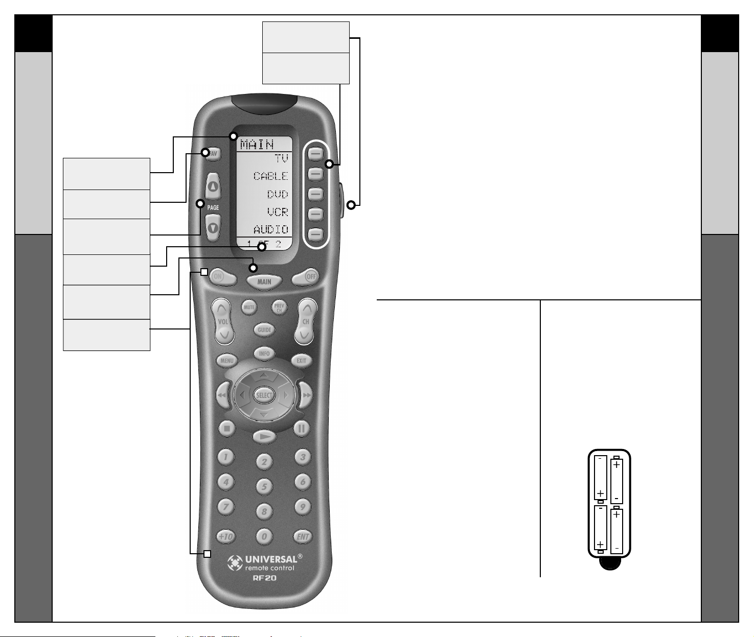
Keypad Layout
CONTROL LOCATIONS
GETTING STARTED
Overview & Battery Installation
Battery Installation
The very first step is to
insert the four AAA
batteries that are included
in the package into the
battery compartment
located in the back of the
remote. Just press the tab
and lift off the cover.
Please be sure to insert the
batteries correctly as you
see in the diagram.
Remember, there is a
positive and negative end to
each battery and you can
tell by the + (positive) and
- (negative) symbols. Once
the batteries are correctly
installed, replace the cover.
Now you’re ready to start!
Getting Started-Overview
This is what MASTERCONTROL™ RF20 is all about!
The RF20 is designed to operate up to 10 different
Audio/Video Components and is pre-programmed to
operate virtually all brands of TV, VCR, DVD and CD Players,
Cable Set Top Boxes, Satellite Receivers, TiVo and other
DVRs, Audio Components, Tape Decks, Multimedia PCs,
XM Radio, Ipod, X-Box, Lighting Controls and other custom
installation products. It also offers an impressive lineup of
special features designed to provide you with many
time-saving conveniences and enhance your overall
entertainment experience. However, we strongly
recommend that you fully complete all of the Basic Setup
steps before proceeding to customize your RF20 with any of
the special advanced features.
LIGHT
BUTTON
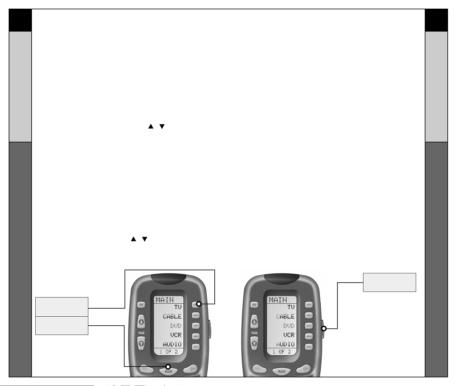
SCREEN-LABELED
DISPLAY BUTTONS
TITLE
FAVORITE
CHANNEL
BUTTONS
changes the page of
buttons displayed
PAG E
NUMBERS
MAIN
BUTTON
takes you to the main menu
FUNCTION
BUTTONS
PAGE
Page 10
LIGHT
BUTTON
MAIN
BUTTON
TV DEVICE
BUTTON
5 6
Activating Component Commands
GETTING STARTED
GETTING STARTED
LIGHT BUTTON
Activating Component Commands –
Simple, Easy, Intuitive
Once you’ve programmed
RF20 for your Components,
all you have to do to operate
a specific Component is
first, press the MAIN button. This will display Page 1
of the MAIN menu on the
LCD screen. Page 1 of the
MAIN menu displays five
Components. Then, simply
select the Component you
want to operate by pressing
the corresponding ScreenLabeled Component Display
Button on the right side of
the LCD Screen. As an
example, if you press the TV
Display Button, the display
label at the top of the
screen will change from
MAIN to TV, and all the buttons on RF20 will work your
TV. To operate another
Component, simply press
the MAIN button again to
return to Page 1 of the
Light Button
The fully backlit keypad makes the RF20 easy to use in the
dark or dim lighting conditions. Simply press the LIGHT
button to backlight all the keypad buttons and LCD screen.
To turn off the backlight, press the LIGHT button again, or
just wait ten seconds (the backlight automatically shuts
itself off). Lights out!
Try it out!
MAIN menu and select the
next Component you want
to operate.
If you don’t see the
Component you want to
control on Page 1 of the
MAIN menu, just use the
PAGE (
) ( ) buttons on the
left side of the screen to
bring up Page 2 of the
MAIN menu which displays
an additional five
Components.
Each Component is
provided with five pages of
pre-labeled command
display buttons (or space
for additional command
display buttons). Once
again, simply use the PAGE
(
) ( ) buttons to take you to
the next command page, or
return you to the previous
command page.
Page 11
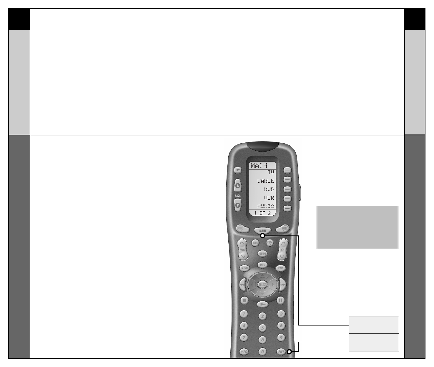
MAIN
ENTER
BUTTON
BUTTON
7 8
Overview &
Pre-Programmed Code Method
BASIC SETUP
BASIC SETUP
Pre-Programmed Code Method
STEP 1:
The pre-programmed 3-digit
codes are found in the back of
this Manual on page 44. The
codes are listed by Component
category (i.e., TV, VCR, DVD,
etc.), then by brand name. For
instance, if you want to locate
a code for a Sony TV, first
locate the TV category, and
then look for the Sony brand.
Once you have located the
3-digit code (or in some cases,
several code numbers) for the
Component that you want to
operate with your RF20, write
them ALL down on a piece of
note paper. It’s important that
you write down all the codes
because only one code is going
to work for you.
STEP 2:
Now, turn on the Component
you want to program... let’s say
your TV to start. Look up your
TV’s manufacturer setup code
from your reference list.
STEP 3:
Press and hold the MAIN and ENT
(Enter) buttons at the same time
for approximately 3 seconds, until
the word “SETUP” is displayed at
the top of the LCD screen. This
signals that you are now in setup
mode.
Pre-Programmed Code Method
Basic Setup - Overview
There are two ways to program the RF20:
• The Pre-Programmed Code Method
• The Learning Method
The Pre-Programmed Code Method allows you to set up
all the buttons at once, so it’s the fastest and easiest of
the two methods. The Learning Method allows you to
transfer functions from other remotes (old or new), one
button at a time.
IMPORTANT:
You now have 30 seconds to perform
the next step while you are in SETUP
mode. If you don’t press a button
within 30 seconds, SETUP will disappear from the screen, signaling that
you have exited setup mode and you
will need to start over.
Page 12
9 10
Pre-Programmed Code Method
BASIC SETUP
BASIC SETUP
Pre-Programmed Code Method
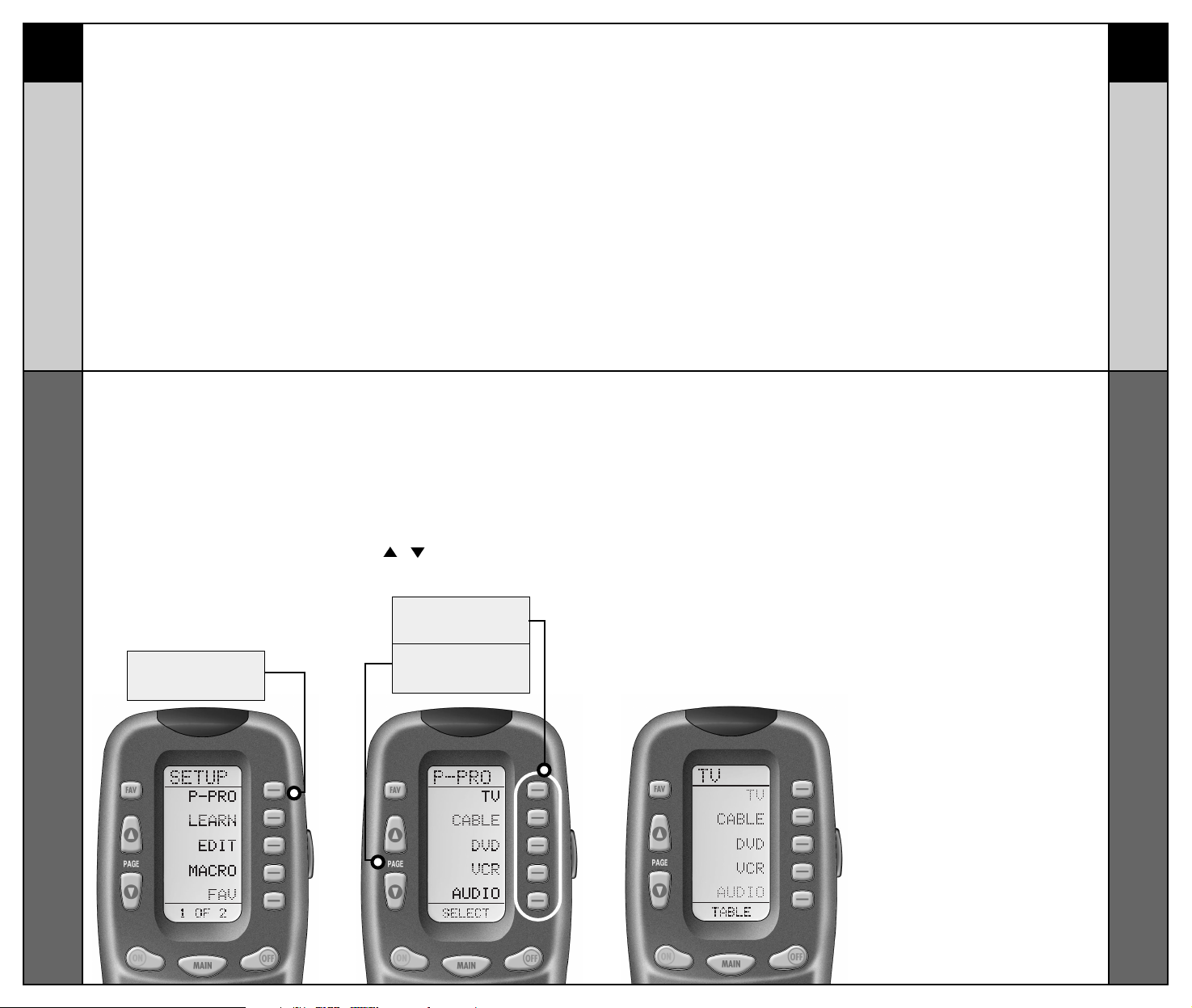
P-PRO
BUTTON
FIRST FIVE
DEVICE NAMES
PAGE
BUTTONS
STEP 6:
In this step you verify the type
of component you plan to
operate with this component
button. For example: If you plan
to operate the TV component
with the TV button, simply press
the TV display button once
again. However, if for example
you are setting up AUX to
operate a second DVD Player,
you would first need to press
AUX in Step 5, and then DVD
in Step 6.
STEP 5:
Press the Component display
button you want to program.
For example: If you want to
setup the TV Component
button, press the TV
Component display button. The
display at the bottom of the LCD
screen will flash
“FROM - TABLE”.
The screen will then display the
five Components from Page 1 of
the MAIN menu.
To display Page 2 of the MAIN
menu that lists an additional five
Components, simply press the
PAGE ( ) ( ) buttons.
STEP 4:
Press the P-PRO display button
to select the Pre-Programmed
Method.
Page 13
ON
BUTTON
VOLUME
BUTTONS
CHANNEL
BUTTONS
PLAY
BUTTON
STOP
BUTTON
NUMBER
BUTTONS
UP & DOWN
BUTTONS
11 12
Pre-Programmed Code Method
BASIC SETUP
BASIC SETUP
Pre-Programmed Code Methoda
NOTE:
If the Component fails to turn off after you have
entered all the code numbers listed for your brand,
you can scan through all the other code numbers
that are pre-loaded into the RF20 for that Component
(in this case TV) by using the UP or DOWN display
buttons on the screen. (There is a chance that your
Component was actually manufactured by another
brand.) However, most of the code tables are so
large that it is usually faster to use the Learning
Method on Page 15.
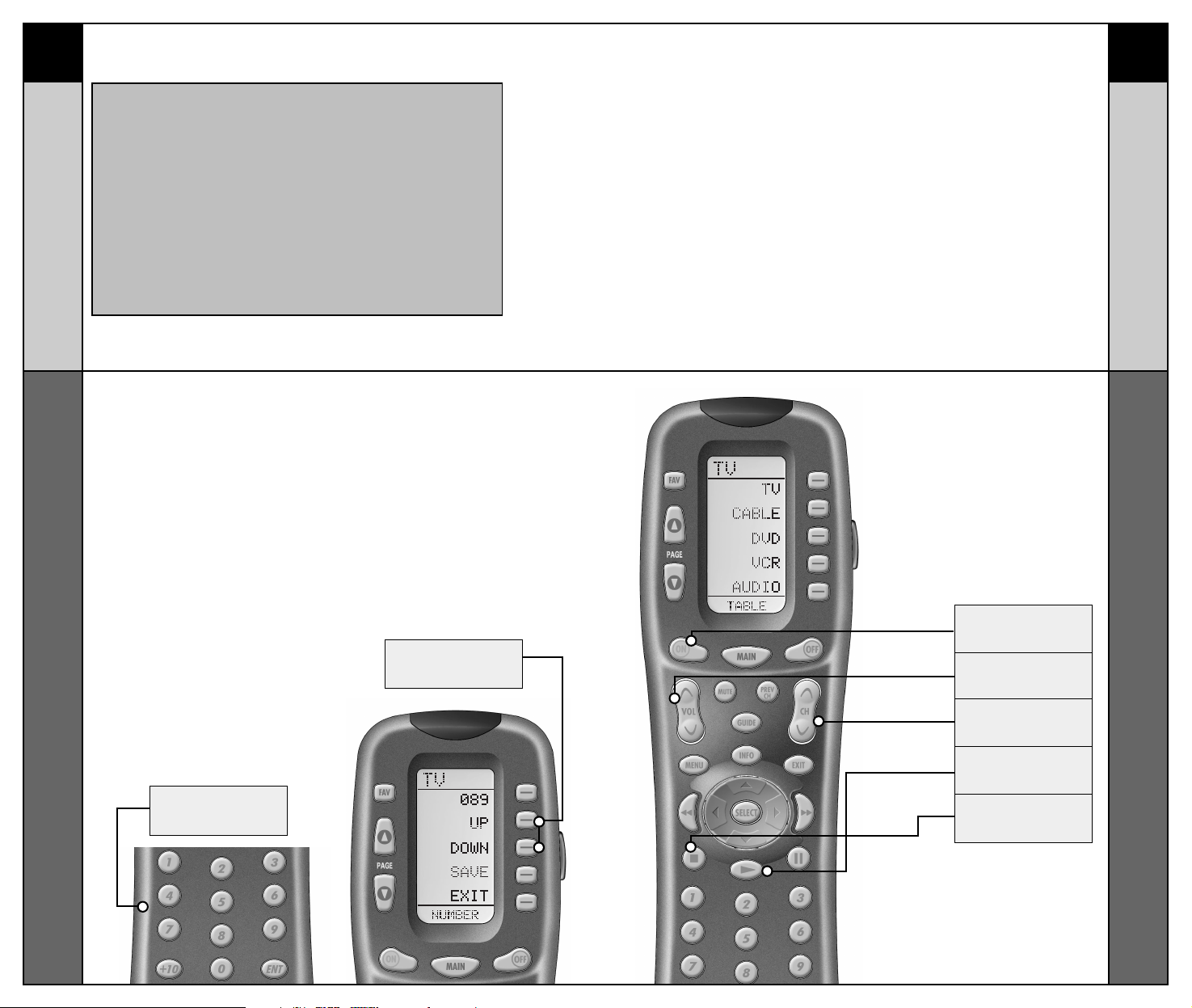
STEP 7:
Point the RF20 toward the
Component you want to
program, (in this example, TV),
and punch in the 3-digit code
that you wrote down for that
specific Component. Use the
Number buttons 0-9 on the
remote to punch in the code.
If the 3-digit code number that
you just punched in is correct,
the Component will turn off.
If the Component does not turn
off, continue entering code
numbers from your list until the
Component turns off. Some
brands have several possible
code numbers.
STEP 8:
When the Component turns off,
press the ON button to turn the
Component back on. Now you
can test the Volume and
Channel buttons (for TV), or
PLAY and STOP (for VCR and
DVD) to make sure they all
work. If any of the buttons do
not work properly, you need to
find a new correct code. For
example, maybe your Sony TV
turned off with code number 147,
but the volume controls did not
work properly. If this is the case,
try the next code number listed
for that Component until you find
a perfect match.
Page 14

SAVE
BUTTON
MAIN
BUTTON
13 14
Pre-Programmed Code Method
BASIC SETUP
BASIC SETUP
Pre-Programmed Code Methoda
STEP 9:
Once you have found the right
code, save the code number by
pressing the SAVE display
button that appears on the LCD
screen. The LCD screen will
blink “SAVED” two times,
signaling that the code number
has been successfully saved.
STEP 10:
Exit SETUP mode by pressing
the MAIN button two times.
When the LCD screen displays
MAIN, you are back in normal
operating mode.
NOW, PROGRAM THE REST OF YOUR
COMPONENTS BY REPEATING STEPS 1
THROUGH 9. IN MOST SYSTEMS,YOU
CAN FINISH BASIC SETUP IN JUST A
FEW MINUTES AND PUT ALL YOUR OLD
REMOTES AWAY.
IF YOU ARE STILL MISSING
COMMANDS TO CONTROL ANY OF
YOUR COMPONENTS, USE THE
LEARNING METHOD
ON PAGE 15.
Page 15

15 16
Learning Method
BASIC SETUP
BASIC SETUP
Learning Method
Learning Method
The RF20 can actually ‘learn’ commands from other remote
controls (old or new), one-button-at-a-time, so it will never
become obsolete. RF20 is the last remote you’ll ever need!
Just follow these simple steps:
STEP 1:
Line-up the RF20 with the other
remote control, head-to-head,
one or two inches apart.
STEP 2:
On the RF20, press and hold
the MAIN and ENT (Enter)
buttons at the same time for
approximately three seconds,
until the word “SETUP” is
displayed at the top of the LCD
screen. This signals you are
now in SETUP mode.
STEP 3:
Press the LEARN display button
on the LCD screen. The top of
the screen will change to
“LEARN” and display the five
Components from Page 1 of the
MAIN menu.
STEP 4:
Select the Component you
want to teach commands to
by pressing that Component
display button on the LCD
screen (in this example, TV).
The top of the TV screen will
change to “TV”.
To display Page 2 of the MAIN
menu that lists an additional
five Components, simply press
the PAGE ( ) ( ) buttons.
IMPORTANT
You now have 30 seconds to perform
the next step while you are in SETUP
mode. If you don’t press a button
within 30 seconds, SETUP will disappear from the screen, signaling that
you have exited setup mode and you
will need to start over.
NOTE: If you want to teach any command
to a Component button, press the
desired Component display button once
the top of the screen displays “MAIN”, by
pressing the PAGE button.The top of the
screen wil change to “READY”. Then go to
STEP 6.
MAIN
BUTTON
LEARN
BUTTON
ENTER
BUTTON
Page 16

17 18
Learning Method
BASIC SETUP
BASIC SETUP
Learning Method
STEP 5:
Press any button on the RF20
that you want to teach a
command to. The top of the
screen will change to “READY”
and the bottom of the screen will
display the button name you
pressed.
STEP 6:
Press and hold the button on the
other remote control that you
want to ‘teach’ to the RF20 until
the LCD display on the RF20
changes to either “GOOD” or
“FAILD”. If the “GOOD” label
appears on top of the display,
you were successful. If the
“FAILD” label appears on top
of the display, try ‘teaching’ the
same button to the RF20 once
again by repeating STEPS 5
and 6.
STEP 7:
Now, continue to teach the RF20
any other commands from your
other remotes by repeating
STEPS 4 through 6 (to go
back to STEP 4, simply press
MAIN once).
STEP 8:
Once you have completed
teaching all the button
commands to the RF20, return to
normal operation by pressing the
MAIN button twice.
• Move to another room. Plasma
TVs, sunlight, halogen or quartz
lighting can interfere with the
learning process.
• Even though the old remote
seems to be working fine, put in
fresh alkaline batteries.
• Gradually vary the distance
between the remote controls.
Try 1”, 2” and so on,
up to 4 feet.
• Try tapping the button on your
old remote instead of pressing
and holding it during the
learning process.
Some additional Information
regarding the Learning Process:
• Learned functions override
any existing pre-programmed
functions on the remote control.
• All buttons can be learned
except for the PAGE, MAIN
and LIGHT buttons.
• Learned functions are
automatically erased when
a new function is learned on
the same button.
• Learned functions are retained
even after a different Setup
Code Number is programmed
into the remote.
• To return to an original
pre-programmed function, a
learned function must be erased.
NOTE: If you don't see the display
button you would like to teach on
the LCD screen, use the PAGE
(
) ( ) buttons. The only
buttons you can't teach are the
PAGE and MAIN buttons.
NOTE: Test all your new commands.
If any of them don’t work, try the
Learning Method again, following
these suggestions:
Page 17

19 20
Transmitting (Busy Signal) Icon
BASIC SETUP
CUSTOMIZING
Customizing the LCD Screen
Transmitting (Busy Signal) Icon
When a command is being transmitted, an icon will appear
in the upper right corner of the LCD screen. This indicates
that a signal is being sent. This is particularly useful when
setting up Macros and FAVs, since it flashes with every step
of a sequence of commands.
CHILD LOCK FEATURE
This ‘child-lock’ feature prevents the unauthorized use of
the remote control by children. It blocks all operations of
the remote control.
To Activate:
Press the +10 and ENT (Enter) buttons simultaneously for
3 seconds. The bottom of the LCD will blink “LOCKED” three
times and then display “LOCKED”.
To Return to Normal Operation:
Press the +10 and ENT (Enter) buttons simultaneously again
for 3 seconds. The LCD will display the last use mode.
Customizing Your RF20 with Special
Advanced Features
After you’ve finished all your basic setup, you can choose
to make operation easier by customizing the RF20 just the
way you want, using the Special Advanced Setup Features
described in this section.
Customizing the LCD Screen
You can easily edit or change the name of any of the
display buttons (including Favorite Channels) on the LCD
screen by following these steps:
STEP 1:
Press and hold the MAIN and
ENT (Enter) buttons at the same
time for approximately 3
seconds, until the word “SETUP”
is displayed at the top of the LCD
screen. This signals that you are
now in setup mode.
STEP 2:
Press the EDIT display button.
The LCD display will change to
the EDIT menu.
STEP 3:
Press the TEXT display button.
The screen will display the list of
Components and “EDIT” will
appear at the top of the screen.
STEP 4:
Navigate to the Component and
page where there is a button
label you want to EDIT, selecting
between the FAV, MAIN, COMPONENT display buttons; then
using the PAGE button.
IMPORTANT:You now have 30 seconds to
perform the next step while you are in
SETUP mode. If you don’t press a button
within 30 seconds, SETUP will disappear
from the screen, signaling that you have
exited setup mode and you will need to
start over.
NOTE: If you wish to change the name of
a Component button, press the Page (
)
Up button twice.The top of the display
will change to MAIN, and you can navigate to MAIN page 1 or page 2 before
going on to Step 5.
Page 18

LEFT CURSOR
Moves blinking
character left
DOWN CURSOR
deletes the currently
blinking character
RIGHT CURSOR
BLINKING
CHARACTER
UP CURSOR
Button deletes all text
Moves blinking
character right
21 22
Customizing the LCD Screen
CUSTOMIZING
CUSTOMIZING
Customizing the LCD Screen
STEP 5:
Press the button you wish to
edit. The first character space
of your button label will start
to blink.
STEP 6:
Change the character by
using any of the number keys.
Each press of the same number
button selects the next
character of that number’s
group, as shown in the
diagram below.
STEP 7:
Once the character you want
appears, move to the next space
by pressing the Right
cursor button.
STEP 8:
When you are finished editing
the button, press the button you
edited and “SAVED” will flash at
the bottom of the display.
To change any other button
labels on the same Component,
press the next button, then
repeat steps 6-8. If you wish to
edit a button on another
Component, press the MAIN button once, then repeat Steps 4-8.
STEP 9:
Once you’ve finished editing
buttons, press the MAIN button
four times to return to normal
operation.
Page 19

2423
Favorite Channel Setup
CUSTOMIZING
Favorite Channel Setup
CUSTOMIZING
Favorite Channel Setup
This is one of RF20’s most desirable features. Once it’s set
up, you can select up to 40 favorite channels with the press
of a button - without the need to remember or type in a
channel number. Let the channel surfing begin!
To access Favorite Channel listings, simply press the FAV
button to display Page 1 of Favorite Channel listings. There
are eight pages of Favorite Channels, with five Channels on
each page, for a total of 40 Channels. Just use the PAGE (
)
( ) buttons to locate the Channel you want to setup. Each
Channel can be setup to be instantly selected with the press
of one button.
To setup a Favorite Channel button, follow these steps:
STEP 1:
Press and hold the MAIN and
ENT (Enter) buttons at the same
time for approximately 3 seconds,
until the word “SETUP” is
displayed at the top of the LCD
screen. This signals that you are
now in setup mode.
STEP 2:
Press the FAV display button.
The top of the display will show
“FAV”. The bottom of the display
will flash “SELECT”
STEP 3:
Use the PAGE ( )( ) buttons
until you locate the name
(i.e.,ABC, CBS, NBC) of the
favorite channel you want to
setup.
STEP 4:
Press the favorite channel
display button you want to setup.
The top of the screen will
change to show the channel
name. The bottom of the screen
displays “STEP0”, indicating that
you have not entered the
channel number yet.
STEP 5:
Press either the TV, SAT or
CABLE Component button (select
the Component you use to enter
channel numbers).
STEP 6:
Press each of the number buttons
for the channel.
Note: If a number is repeated when setting the channel (for example, channel
“33” or “522”), it is usually best to set a
half second delay in between the identical numbers by pressing the (II) PAUSE
button. Each press of the PAUSE button
increases the delay by a half second.
NOTE: Some brands of television
require an ENT (Enter) command after
the channel numbers.
IMPORTANT:
You now have 30 seconds to perform
the next step while you are in SETUP
mode. If you don’t press a button
within 30 seconds, SETUP will disappear from the screen, signaling that
you have exited setup mode and you
will need to start over.
FAV
BUTTON
PAUSE
BUTTON
Page 20

25 26
Favorite Channel Setup
CUSTOMIZING
CUSTOMIZING
MacroPower
™
Setup
STEP 7:
Press the LIGHT button after you
enter the channel number.
A new screen appears displaying
SAVE, UNDO or EXIT.
STEP 8:
To save the channel you
entered, press the SAVE display
button. The UNDO display button
lets you erase the last entry. The
EXIT display button erases all
entries for this button.
STEP 9:
When you are finished setting
up Favorite Channel buttons,
press the MAIN button twice to
return to normal operation.
STEP 1:
Press and hold the MAIN and
ENT (Enter) buttons at the same
time for approximately 3 seconds,
until the word “SETUP” is
displayed at the top of the LCD
touch screen. This signals that
you are now in setup mode.
STEP 4:
Press the first component display button you want the Macro
to turn on (in this example, TV)
and “TV” will display at the top
of the screen and “STEP 1” at
the bottom.
STEP 5:
Then, press the ON button to
confirm the command and “STEP
2” will display at the bottom of
the screen. (NOTE: Whenever a
button is pressed, another
Macro step is counted and displayed at the bottom of the
screen.)
STEP 6:
Now, press the MAIN button to
return to the Main Component
listing. (“STEP 3” will display at
the bottom of the screen.)
STEP 2:
Press the MACRO display button
on the LCD screen. The top of
the screen will display
“MACRO”. The bottom of the
display will flash “SELECT”.
STEP 3:
Press the ON button. “ON” will
display at the top of the LCD
screen. “STEP0” will display at
the bottom of the screen indicating
that no macro steps have
been entered yet.
MacroPower™ Setup
MacroPower™ is a unique feature that enables you to turn
all of your Components ON or OFF, at the same time, simply
with the press of one button.
We call that a “Macro”. What would normally take multiple
remotes and button pushes, the RF20 can accomplish with
the press of one button. In addition to the Power ON or OFF
buttons, any of the Display buttons (on any Component or
Page) can be set to be Macro buttons as well. Feel the
power!
To setup a Power ON macro button that will turn ON several
components at the same time (for example, TV, VCR and
CABLE), follow these easy steps:
IMPORTANT: You now have 30 seconds to
perform the next step while you are in
SETUP mode. If you don’t press a button
within 30 seconds, SETUP will disappear
from the screen, signaling that you have
exited setup mode and you will need to
start over.
SAVE
BUTTON
Page 21

SAVE
BUTTON
UNDO
BUTTON
EXIT
BUTTON
27 28
MacroPower
™
Setup
CUSTOMIZING
CUSTOMIZING
MacroPower
™
Setup
STEP 7:
Press the second component
display button that you want the
Macro to turn on (in this example,
VCR) and “VCR” will display
at the top of the screen. (“STEP
4” will display at the bottom of
the screen.)
STEP 8:
Then, press the ON button to
confirm the command. (“STEP
5” will display at the bottom of
the screen.)
STEP 9:
Now, press the MAIN button to
return to the Main Component
listing. (“STEP 6” will display at
the bottom of the screen.)
STEP 10:
Press the third component display button that you want the
Macro to turn on (in this example, CABLE) and “CABLE” will
display at the top of the screen.
(“STEP 7” will display at the bottom of the screen.)
STEP 11:
Then, press the ON button to
confirm the command. (“STEP
8” will display at the bottom of
the screen.)
You can also program delays in
between commands by pressing
the (II) PAUSE button. Each
press adds half a second to the
delay.
STEP 12:
Press the LIGHT button to end
your macro. A new screen will
appear:
STEP 13:
If you are satisfied with your
macro, press the SAVE display
button. The UNDO display button
lets you erase the last step.
The EXIT display button erases
all the macro steps.
STEP 14:
Press the MAIN button twice to
return to normal operation.
NOTE : Don’t worry about the number of
steps. Each macro button can store up to
190 steps, so you are not likely to run out
of steps!
Page 22

VOLUME
BUTTON
29 30
MacroPower
™
Setup
CUSTOMIZING
CUSTOMIZING
SimpleSound Setup &
Other ‘Punch Throughs’
Advanced Macro Options:
SETTING UP A POWER OFF MACRO:
Simply follow the same steps as outlined above, except
press the OFF button in place of the ON button.
SETTING A COMPONENT BUTTON AS MACRO:
If you wish to set one of the Component buttons as a
macro, in STEP 3, press the Page Up button twice. The top
of the display will change to MAIN, and you can navigate to
MAIN page 1 or page 2. Press the Component button you
want to set as a Macro button. The top of the screen will
display the button label you selected. Select the
Component and Page that has a button you want in your
Macro using the MAIN, Component and Page buttons.
Simply press the button(s) with the command(s) you want
in your Macro. Then complete and save the Macro by
following STEPs 12 and 13 as outlined above.
PROGRAMMING A “PRESS & HOLD” MACRO:
Another option for Component button macros is to only
send the macro if the button is pressed and held. This is
setup by entering a delay as the first step of the macro.
The amount of delay determines how long the user must
press the button before the macro is sent. The advantage
of this option is that a normal press of the COMPONENT
button will simply switch Components without sending the
macro command.
SimpleSound™ Setup & Other ‘Punch Throughs’
SimpleSound™ is a dynamic feature that gives you total
volume control over all the Components in your system,
even those without their own built-in volume control, such
as TiVo, DVD and VCR... saving you the hassle and
inconvenience of constantly needing to switch between
Component modes on the remote. With SimpleSound™,
you can set the RF20’s volume control buttons to always
control the sound in your system, even when you’re in VCR
or DVD mode, without switching back to AUDIO or TV.
Even more exciting, SimpleSound™ is what is called a
‘Punch Through’ feature and is not limited strictly to volume
control. Click and enjoy!
STEP 1:
In a basic home entertainment
system, the sound may come
from your TV. In a more
advanced system, the sound
may come from your audio
Component such as a Surround
Sound Receiver or Home
Theatre system. So, first, you
need to identify which
Component you want to use in
your system for sound.
STEP 2:
Press and hold the MAIN and
ENT (Enter) buttons at the same
time for approximately 3
seconds, until the word “SETUP”
is displayed at the top of the LCD
screen. This signals that you are
now in setup mode.
STEP 3:
Press the PAGE ( ) UP button to
display Page 2 of the Setup
Menu on the LCD screen. Press
the PUNCH display button.
STEP 4:
Then press the VOL (Volume)
display button. The screen will
display “VOL” at the top. This
sets up the group of three
buttons (Volume Up, Volume
Down and Mute) in one action!
IMPORTANT:You now have 30 seconds to
perform the next step while you are in
SETUP mode. If you don’t press a button
within 30 seconds, SETUP will disappear
from the screen, signaling that you have
exited setup mode and you will need to
start over.
Page 23

MAIN
BUTTON
UP & DOWN
CURSOR
HIGH
CONTRAST
LOW
CONTRAST
31 32
SimpleSound Setup &
Other "Punch Throughs"
CUSTOMIZING
CUSTOMIZING
Setting Backlight Options
NOTE: If you want to PUNCH TO the MAIN
Component, press the POWER OFF button
at this time.
NOTE:The Punch Through feature is not
limited to volume and can also be applied
to channel selection or other functions. If
you find yourself switching to a particular
Component frequently to use a group of
controls, consider using Punch Through for
another group, as listed here:
VOL Volume Up,Volume Down
and Mute
CH Channel Up, Channel Down,
Previous Ch and Channel
(0-9) buttons.
PLAY Play, Stop, Pause, Rewind
and Fast Forward
VOD Guide, Menu, Info, Exit, Up,
Down, Left, Right, Select
The bottom of the display flashes
“PUNCH TO”. Press the button
for the Component that doesn’t
have volume control commands
yet (i.e.,DVD). This is the
Component you are going to
PUNCH TO for the volume and
mute commands.
STEP 5:
The bottom of the display will
then flash “PUNCH FROM”. Now
select the Component that has
the volume commands you want
to use (i.e.,TV for systems using
the TV speakers, AUDIO for systems with surround sound
receivers). The bottom of the display will flash “SAVED”.
STEP 6:
Repeat STEPS 4-5 until all your
Components operate the volume
perfectly.
STEP 7:
Press the MAIN button twice to
return to normal operating
mode and test your
SimpleSound™ settings.
Simply perform the steps outlined
above, but in STEP 4, press one
of the control options (CH, PLAY or
VOD).
Setting Backlight Options
You can customize the backlighting feature to suit your
specific preferences by following these simple steps:
Adjusting Length of Backlight Time
You can adjust the amount of time that the RF20 backlight
stays on by entering the SETUP mode and proceeding to
page 2 (using the PAGE (
) UP button), then pressing the
LIGHT display button on the LCD screen (not the Backlight
button). Then enter the amount of time you would like the
light to stay on using the number pad (0-99 seconds). After
making your selection, press the SAVE display button.
Adjusting Contrast
You can make the text darker by pressing both the MAIN and
cursor UP buttons at the same time. To make the text appear
lighter, press both the MAIN and cursor DOWN buttons at the
same time.
Turning OFF Backlighting
If you don’t want backlighting at all (this extends battery
life), press the ON display button that appears on the
screen. The ON will change to OFF. Press the SAVE display
button. Exit the setup mode by pressing the MAIN button.
Page 24

FAV
BUTTON
PAG E
BUTTON
MAIN
BUTTON
COMPONENT
BUTTONS
EDIT
BUTTON
PAG E
BUTTON
33 34
Hiding and Adding Pages
CUSTOMIZING
CUSTOMIZING
Hiding and Adding Pages
Hiding and Adding Pages
Each of your RF20 Components actually contains eight
pages. However, only five pages are visible in the factory
default setting. Three page are hidden in each Component.
If you wish to use the hidden pages, you can ADD it. If you
don’t want to use some of the existing pages, you can HIDE
them. You can add or hide pages on Components OR on
your favorite channel pages using this simple process:
STEP 1:
Press and hold the MAIN and
ENT (Enter) buttons at the same
time for approximately 3
seconds, until the word “SETUP”
is displayed at the top of the LCD
screen. This signals that you are
now in setup mode.
STEP 2:
Press the EDIT display button on
the LCD screen.
STEP 3:
Press the PAGE display button
once the screen changes to
EDIT mode.
STEP 5:
When you select a page, the top
of the screen indicates whether
you want to “ADD?” or “HIDE?”
the page displayed. When you
want to change a page’s visibility
(i.e., either ADD or HIDE), simply
press the LIGHT button.
STEP 6:
You can continue to ADD or
HIDE pages on other
Components by repeating
Steps 4 and 5.
STEP 7:
When you are finished
adding and hiding pages,
press the MAIN button four
times to return to normal
operation.
IMPORTANT:You now have 30 seconds to
perform the next step while you are in
SETUP mode. If you don’t press a button
within 30 seconds, SETUP will disappear
from the screen, signaling that you have
exited setup mode and you will need to
start over.
NOTE: Be sure to program your Macros before you hide pages
with potential macros in them. You can’t access hidden pages
during macro setup. However, after you finish Macro setup, you
can hide pages without affecting operation of your macros.
STEP 4:
“PAGE” appears at the top of the
screen. Now, you can navigate
to any page, using the MAIN,
COMPONENT, FAV, and PAGE
display buttons.
This page is hidden. To ADD
it, press the LIGHT button.
This page is visible.To HIDE
it, press the LIGHT button.
Page 25

35 36
Recalling Pre-Programmed
Setup Code Numbers
CUSTOMIZING
CUSTOMIZING
Cloning Other RF20s
Recalling Pre-Programmed Setup Code
Numbers
In case you didn’t write down the Pre-Programmed Code
Numbers that you used to set up your RF20, you can easily
recall them using this simple process:
STEP 1:
Press and hold the MAIN and
ENT (Enter) buttons at the same
time for approximately 3 seconds,
until the word “SETUP” is
displayed at the top of the LCD
touch screen. This signals that
you are now in setup mode.
STEP 4:
Write down the code numbers
as they appear for future reference. Page 43 of this manual
provides a convenient space for
you to record your code
numbers.
STEP 5:
Return to normal operation by
pressing the MAIN button twice.
STEP 4:
Align the two RF20s head-tohead, about an inch apart.
STEP 5:
Press the RECV display button
on the unprogrammed RF20 that
you want to setup by cloning.
STEP 6:
Press the SEND display button
on the programmed RF20 that
you want to clone.
STEP 7:
Press the START button on the
unprogrammed RF20, and then
press the START button on the
programmed RF20 that you want
to clone.
STEP 8:
Return to normal operation by
pressing the MAIN button twice.
STEP 2:
Go to Page 2 of the Setup Menu
by pressing the PAGE ( ) button.
STEP 3:
Press the RECAL display button
on the LCD screen. The display
will change to the Recall
screens. The screen automatically switches between four
screens, alternately flashing
Page 1 components and code
numbers, then Page 2 components and code numbers.
STEP 2:
Press a PAGE button on each
remote to bring up Page 2 of
Setup and display the CLONE
button.
STEP 3:
Press the CLONE button on each
remote.
IMPORTANT:You now have 30 seconds to
perform the next step while you are in
SETUP mode. If you don’t press a button
within 30 seconds, SETUP will disappear
from the screen, signaling that you have
exited setup mode and you will need to
start over.
Cloning Other RF20s
If you are fortunate enough to own more than one RF20,
you’ll be happy to know that you can easily copy and transfer all the setup from one RF20 to another. Just follow these
easy steps:
STEP 1:
For both the programmed RF20
that you want to clone, and
unprogrammed RF20, press and
hold the MAIN and ENT (Enter)
buttons at the same time for
approximately 3 seconds, until
the word “SETUP” is displayed
at the top of their respective LCD
screens. This signals that both
remotes are now in setup mode.
IMPORTANT:You now have 30 seconds to
perform the next step while you are in
SETUP mode. If you don’t press a button
within 30 seconds, SETUP will disappear
from the screen, signaling that you have
exited setup mode and you will need to
start over.
NOTE: Cloning typically takes about 40
seconds. After successful cloning is completed, the newly cloned RF20 will flash
“GOOD”.
Page 26

37 38
Erasing Learned Buttons, Macros or
Favorite Channels
ERASING COMMANDS
ERASING COMMANDS
Erasing Learned Buttons, Macros or
Favorite Channels
Erasing Commands - Overview
You can erase an individual button with a learned command, a macro or a favorite channel. You can erase an
ENTIRE Component’s learned command or macro buttons.
You can also erase ALL your learned commands on all
Components or all your macros or favorite channels everywhere.
If you really want a fresh start, it is possible to reset everything to the factory default settings.
Erasing Learned Buttons, Macros or Favorite Channels
STEP 2:
Press a PAGE button to display
Page 2 of Setup.
STEP 3:
Press the ERASE display button
on the LCD screen.
STEP 4:
Press either the LEARN, MACRO
or FAV button. The following
screen appears:
ALL - Erases ALL of the specified (Learned, Macro or FAV buttons everywhere in the RF20)
DEVICE - Erases all learned or
Macro buttons in a single
Component (NOTE: This option
is not available for FAVs.)
KEY - Erases one button only.
STEP 1:
Press and hold the MAIN and
ENT (Enter) buttons at the same
time for approximately 3 seconds, until the word “SETUP” is
displayed at the top of the LCD
screen. This signals that you are
now in setup mode.
IMPORTANT:You now have 30 seconds to
perform the next step while you are in
SETUP mode. If you don’t press a button
within 30 seconds, SETUP will disappear
from the screen, signaling that you have
exited setup mode and you will need to
start over.
STEP 5:
If you press ALL, the RF20 displays a “SURE?” button. After
the SURE button is pressed, all
the buttons will be erased.
If you press DEVICE, a list of
Components will appear. Press
the Component button that you
wish to erase. The bottom of the
screen will flash ERASE twice,
then ERASED.
If you press KEY, you’ll have to
navigate to the Component and
Page you want using the MAIN,
COMPONENT and PAGE buttons.
Press a button to erase it. The
bottom of the display will flash
ERASE twice, then ERASED.
STEP6:
To return to normal operating
mode, press the MAIN button
four times.
SURE
BUTTON
Page 27

39 40
Re-setting RF20 to Original
Factory Default Settings
ERASING COMMANDS
ERASING COMMANDS
Re-setting RF20 to Original
Factory Default Settings
STOP
BUTTON
MAIN
BUTTON
SURE
BUTTON
STEP 1:
Press and hold both the
MAIN and the STOP buttons
for 10 seconds.
STEP 2:
After 10 seconds, the RESET
screen appears. Press the ALL
button. The RF20 will display a
“SURE?” button. Press the
SURE button to erase all of your
settings and return to the factory
default setup
Re-setting RF20 to Original
Factory Default Settings
If you want to start with a clean slate, you can re-set the
RF20 its original factory default settings by performing the
following steps.
NOTE: This process will essentially erase EVERYTHING
you have programmed into the RF20.
Page 28

41 42
‘Barrier -Free’ RF control
THE POWER BLASTER
THE POWER BLASTER
The Optional PowerBlaster
TM
(for ‘barrier-free’ RF control)
[Sold separately]
Of all the fabulous RF20 features, this is probably the most
exciting. When used in combination with the optional
PowerBlaster
TM
, the RF20 becomes an amazing remote
control powerhouse that sends multi-directional RF (Radio
Frequency) signals that pass through walls, doors and
floors - both indoors and outdoors.
This changes everything! It enables you to control
Components that are completely out-of-sight, up to 100’
away. The PowerBlaster
TM
picks up RF20’s radio frequency
signals from any direction, regardless of distance, so RF20
doesn’t need to be pointed directly at any Component. Just
imagine - no more pointing! Now you can close your
entertainment center doors, hide your Components, and
still control them with ease. Control outdoor speakers on
your patio. Control your Components anywhere!
One of the best things about this is -- nothing has to be
done to the RF20 for this feature to work.
Every time you press a button on the RF20, it sends both a
standard IR (Infrared Command) AND an RF (Radio Frequency) signal. If you install the PowerBlaster
TM
kit, it will
automatically receive RF20’s radio signals and translate them
into the infrared commands that control your Components.
The RF20 sends radio signal to the PowerBlaster
TM
, which
is a radio receiver
The PowerBlasterTMconverts radio signals to standard
infrared commands and sends them out via a built-in front
blaster to Components in the same cabinet space.
Self-adhesive “flashers” (included in the PowerBlaster
TM
kit) affix to the front panels of your Components. The
flashers relay infrared commands to Components out-ofsight of the PowerBlaster’s front blaster. The flashers plug
into PowerBlaster’s rear flasher line output jacks. Each
flasher has a 10’ cable to easily reach Components on
nearby shelves.
NOTE: The RF20's radio signals will not control Components
directly. You must have a PowerBlaster
TM
to receive the
RF20's radio signals. Components that came with "no pointing" radio remote controls cannot be operated by the RF20
unless the Component can be switched to standard IR
(Infrared Control) via its internal menus. Some remote control ceiling fans are radio only and cannot be operated by
the RF20.
‘Barrier -Free’ RF control
Page 29

44
PRE-PROGRAMMED CODE TABLES
Pre-Programmed Code Tables
43
Pre-Programmed Code Notes
PRE-PROGRAMMED CODE NOTES
Pre-Programmed Code Notes
Record the three digit codes for your system here
AUDIO
DVD
CD
SAT
TV
VCR
CABLE
AUX
LIGHT
TAPE
PHONO
TV2
VCR2
DVR
LDP
XM RADIO
IPOD
X-BOX
Pre-Programmed Code Tables
The RF20’s Pre-Programmed code library is divided into
categories (TV, VCR, AUX, etc.). Each category actually
includes many types of Components. For example, the VCR
category includes TV/VCR combo units.
Within each category, the code numbers are listed in rows by
brand (Sony, Panasonic, B & K, etc.). Some brands have more
than one three digit code for you to try. Just circle the correct
row and refer to it while you setup (step by step instructions
for using Pre-Programmed codes are found on page 7).
TV TVs, Plasmas, Projectors and Monitors
CABLE Cable TVs and Web TVs
DVD DVD Players and TV/DVD Combos
VCR VCRs and TV/VCR Combos
AUDIO Amps, Preamps, A/V Receivers and XM Radios
SAT Satellite Receivers
CD CD Players and CD Changers
DVR TiVo, Replay and other DVR’s
AUX Tape Decks, Lighting Controls, Multimedia PCs,
Xbox, iPod and Custom Installation Products
Page 30

46
CODE TABLES
TV
BRAND CODE NUMBERS
45
BRAND CODE NUMBERS
TV
CODE TABLES
ADMIRAL 072 081 161 160
ADVENT 247
AKAI 197 146 248
A MARK 112 143
AMPRO 167 073 157 183
AMSTRAD 052
ANAM 043 054 056 080 112 131
AOC 197 004 112 058
APEX DIGITAL 006 310
AUDIOVOX 076 273
BARCO 233
BLAUPUNKT 088
BROKSONIC 238
CAIRN 201
CANDLE 197 002 003 004
CAPEHART 058
CETRONIC 043
CITIZEN 197 002 003 004 043 101 103 143
CLASSIC 043
CONCERTO 004
CONTEC 043 050 051
CORONADO 143
CRAIG 043 054
CROWN 043 143
CURTIS MATHES 197 101 004 143
CXC 043
DAEWOO 004 016 043 044 076 103 114 125 127 143
DAYTRON 004 143
DELL 319 320 321
DREAMVISION 235 345
DWIN 177 257
DYNASTY 043
DYNATECH 062
EIKI 187
ELECTROHOME 143 024 076 196
EMERSON 028 048 043 155 005 197 004 047 050 051 076 096 143 151
153 154
EPSON 324
ESA 323
FISHER 007 057
FUJITSU 198 246 346
FUNAI 028 043
FUTURETECH 043
GATEWAY 242 268
GE 160 144 165 073 197 008 009 034 056 074 130 155 161 004
091 157 183
GOLDSTAR 113 116 102 004 106 112 119 127 143
HALL MARK 004
HANNSPREE 381
HITACHI 011 163 166 004 009 010 012 023 075 143 158 072
HP 316 327 378
HYUNDAI 337 338
INFINITY 164
INFOCUS 230 330 333
INSIGNIA 350
JBL 164
JCPENNEY 004 024 197 008 009 030 065 101 143 156 160
JENSEN 013
JVC 038 034 070 083 145 199 210 240 241
KEC 043
KENWOOD 197 070
KLOSS 002 059
KMC 143
KTV 043 197 143 154
LG 113 116 102 004 106 112 119 127 143 243 284 363 365
LODGENET 072
LOEWE 164
LOGIK 072
LUXMAN 004
LXI 166 007 015 052 081 160 164
MAGNAVOX 164 059 197 003 060 061 004 063 064 127 022 160 094 239
226 273
MARANTZ 197 164 184
MATSUI 164
MAXENT 242
MEMOREX 007 072 004
METZ 088
MGA 197 004 024 028 042
MINERVA 088
MITSUBISHI 109 124 024 004 028 040 042 146 191
MTC 197 004 062 101
NAD 015 025
NEC 132 130 134 197 040 016 024 056 019 236 237 262 272
NIKEI 043
NUVISION 351
ONKING 043
ONWA 043
OPTONICA 019 081
OPTOMA 265 270
ORION 096
PANASONIC 034 056 080 092 164 208
PHILCO 197 003 059 060 064 164 004 024 056 063
PHILIPS 164 005 093 038 197 003 004 059 127 184 206 239 259
PIONEER 135 025 197 018 023 116 190 234 335
POLAROID 138 268 328 353 354 356 388
PORTLAND 004 143
PROSCAN 144 160 161 165 167
PROTON 004 131 058 143 171 173 193
QUASAR 034 056 092
RADIO SHACK 019 004 143 043 127
RCA 160 165 065 156 144 161 197 004 024 056 152 023 074 333
REALISTIC 007 019 043 047
ROCTEC 186
RUNCO 168 169 178 179 180 181 182 183 073 157 340
SAMPO 197 058 004 202
SAMSUNG 050 089 101 105 004 127 143 160 228 229 258
SANYO 166 007 020 053 057 082 187
SCEPTRE 276
SCOTT 028 043 004 048 143
SEARS 015 030 004 007 028 057 143 094 160 082 165 166
SELECO 189 200 205 227
SHARP 081 019 014 170 028 029 004 022 143 175 251
SIEMENS 088
SIM2 189 200 205 227
SIGNATURE 072
SOLE 231 232
SONY 070 139 147 126 185 194 085 213 277 279
SOUNDESIGN 028 004 003 043
SPECTRICON 112
SSS 004 043
Page 31

48
CODE TABLES
CABLE / WEBTV
BRAND CODE NUMBERS
47
BRAND CODE NUMBERS
TV
CODE TABLES
SUPRE MACY 002
SVA 328
SYLVANIA 197 003 059 060 063 064 164 044 160 127
SYNTAX OLEVIA 376
TANDY 081
TATUNG 056 062
TECHNICS 034 080
TECHWOOD 004
TEKNIKA 002 003 004 024 028 043 072 101 143
TELEFUNKEN 037 046 086 087
TELERENT 072
TERA 172
TMK 004
TOSHIBA 015 138 030 007 040 062 101 325
TOTEVISION 143
UNIVERSAL 008 009
VIDEO CONCEPTS 146
VIDIKRON 174 184 188 192 340
VIDTECH 004
VIEWSONIC 242
VIZIO 386 387
WARDS 004 008 009 019 028 060 061 063 064 072 074 143 164 034
WESTING HOUSE 076 280
WINBOOK 339
YAMAHA 197 004
YORK 004
YUPITERU 043
ZENITH 073 072 095 103 157 183 243 284
ZONDA 112
ABC 004 103 003 039 042 046 053
ADELPHIA 043 074
ADVANCED NEWHOUSE 043
ALTRIO 043
AMERICAST 099
ARCHER 005 007 014
ARMSTONG 074
AT&T BROADBAND 074
ATLANTIC BROADBAND 043 074
BELL SOUTH 099
BLUE RIDGE 043 074
BRESNAN 074
BRIGHT HOUSE 043 110
BUCKEYE COMM 074
CABLEVISION 043 074 108
CENTURION 092
CENTURY 007
CHARTER 043 074
CITIZEN 007
COGECO 074
COMBANO 080 081
COMCAST 043 074 110
COMSAT 074
COX DIGITAL 043 074
DIGICABLE 101
EAGLE 020 030 040
EASTERN 057 066
ECHOSTAR 106
ELECTRICORD 032
GEMINI 008 054
GENERAL ELECTRIC 072
GENERAL INSTRUMENT 074 103 104
GNC 099
GOLDEN CHANNEL 030
HAMLIN 049 050 055
HITACHI 103 055
INSIGHT 074
JERROLD 074 004 103 002 003 008 009 010 069
MAGNAVOX 010 012 064 079 095 094
MASSILLON 074
MEDIA ONE 107
MEDICOM 074
MEMOREX 052
MITSUBISHI 102
MOTOROLA 074 110 109 111
MOVIE TIME 028 032
MOXI 111
NCTC 074
NSC 015 028 038 071
OAK 031 037 053
PACE 043 074
PANASONIC 044 047
PARAGON 052
PHILIPS 006 012 013 020 085 095
PIONEER 043 103 034 051 063 076 105
PRUCER 059
PULSAR 052
RCA 047
RCN 074
RECOTON 098
Page 32

50
CODE TABLES
DVD
BRAND CODE NUMBERS
49
BRAND CODE NUMBERS
CABLE / WEBTV
CODE TABLES
REGAL 049 050
REGENCY 057
RODGERS 043
SAMSUNG 030
SCIENTIFIC ATLANTA 043 011 003 041 042 045 046
SEREN 043
SERVICE ELECTRIC 074
SHAW 074
SIGECOM 043
SONY 096 108
SPRUCER 047 078
STARCOM 002 004 008 009
STARGATE 008 030 097 104
SUSQUEHANNA 043 074
TIME WARNER 043 074
TOCOM 039 040 056
TOSHIBA 052
UNITED CABLE 004 053
UNIVERSAL 005 007 014 032 035
VIDEOTRON 043
VIEWSTAR 012 015 018 086 087 088 089
WIDE OPEN WEST 043 099
ZENITH 052 060 093 100
AIWA 146
ALPINE 098
APEX DIGITAL 087 111 115 112 116
ARCAM 122
CAMBRIDGE AUDIO 215
CARY AUDIO DESIGN 174
CLASSE 167
COBY 258
DENON 007 080 173
FUNAI 143
GATEWAT 175
GE 026 027
GO VIDEO 137 218 220 221 222
HARMAN KARDON 084 140
HITACHI 101
ILO 268
INTEGRA 142 180
JVC 012
KENWOOD 151
KISS 179 279
KLH 135
KRELL 104
LEXICON 148
LG 091 057 074
LITEON 264 265
MAGNAVOX 066 096
MALATA 267
MARANTZ 083 095
MERIDIAN 153
MITSUBISHI 017
MYRYAD 102 134
NAD 088 155
NAKAMICHI 103
ONKYO 076 035 180
OPPO 266
PANASONIC 021 042 138 139 144 150
PHILIPS 066 083 095 105 166
PIONEER 023 092 099 107 108 131
POLAROID 233 234 237
PRIMARE 193 194
PROCEED 086
PROSCAN 026 027
RCA 026 027
RJTECH 269
ROTEL 204
SAMSUNG 056 070 119 165 170 137 159
SANSUI 154
SANYO 147
SENSORY SCIENCE 222 223
SHARP 094
SONY 033 118 145 126 191
SYLVANIA 143
SYMPHONIC 143
TAG MCLAREN 156
TATUNG 102
TEAC 270
THOMPSON 026 027
THULE 177
TOSHIBA 035 034 130 141 164 188
VENTURER 149
Page 33

52
CODE TABLES
DVD
BRAND CODE NUMBERS
51
BRAND CODE NUMBERS
DVD
CODE TABLES
VINC 161
YAMAHA 042 089 166 195 197
ZENITH 057 074 091
DVD-TV/DVD Combos
AIWA 146
FUNAI 143
SAMSUNG 165
SYLVANIA 143
SYMPHONIC 143
TOSHIBA 130
DVD-TV/DVD/VCR Combos
MAGNAVOX 143
PANASONIC 144
SYLVANIA 143
TOSHIBA 164
DVD-DVD/VCR Combos
GO VIDEO 137 218
PANASONIC 150
PHILIPS 105 (VCR Functions for VCR 067)
POLAROID 234
SAMSUNG 137 159
SANSUI 154
SONY 145 191
TOSHIBA 141
ZENITH 091 (VCR Functions for VCR171)
DVD-DVD Recorder
GATEWAY 175
GO VIDEO 220 221 222
ILO 268
KISS 279
LITEON 265
PANASONIC 139
SENSORY SCIENCE 222
SONY 191
TOSHIBA 188
DVD-LD
DENON 206 207
FUNAI 120
KENWOOD 152 013
MAGNAVOX 032 121
MARANTZ 211
MITSUBISHI 121
NAD 121
OPTIMUS 049 013
PANASONIC 113
PHILIPS 032
PIONEER 106 117 121
RADIO SHACK 120
RCA 002
REALISTIC 049
RUNCO 127
SANYO 075
SHARP 152 013
SONY 053 110
TECHNICS 113
THETA DIGITAL 032
TOSHIBA 152 106
YAMAHA 043 129
Page 34

54
CODE TABLES
VCR
BRAND CODE NUMBERS
53
BRAND CODE NUMBERS
VCR
CODE TABLES
AIWA 034 161
AKAI 016 146 043 046 124 125 142
AMPRO 072
ANAM 031
AUDIO DYNAMICS 012 023 039 043
BROOKSONIC 035 037 129
CANON 028 031
CAPEHART 108
CRAIG 003 040 135
CURTIS MATHES 031 041
DAEWOO 111 116 117 119 005 007 010 065 108 110 112
DAYTRON 108
DBX 012 023 039 043
DYNATECH 034 053
ELECTROHOME 059
EMERSON 006 029 035 017 025 027 031 034 036 037 046 101 129 131
138 153 162 116
FISHER 003 010 008 009
FUNAI 034
GE 031 072 147 063 107 109 144
GO VIDEO 132 136 155 040 115
GOLDSTAR 101 106 114 013 020 012 123
HARMAN KARDON 012 045
HITACHI 004 026 150 018 034 043 063 137 160 013
INSTANTREPLAY 031
JCL 031
JCPENNEY 012 013 015 040 066 101
JENSEN 043
JVC 048 043 130 150 055 060 012 031 050 152 166
KENWOOD 014 048 034 047
LG 101 106 114 013 020 012 123
LLOYD 034
LXI 034 003 009 017 106
MAGIN 040
MAGNAVOX 067 031 034 068 041 156 164
MARANTZ 067 069 012 031 156
MARTA 101
MATSUI 027 030
MEI 031
MEMOREX 101 003 010 014 031 034 053 072 102 134 139
MGA 045 046 059
MINOLTA 013 020
MITSUBISHI 059 061 151 013 020 045 046 051 142 049 168
MTC 034 040
MULTITECH 024 034
NEC 012 023 039 043 048
NORDMENDE 043
OPTONICA 053 054
ORION 025
PANASONIC 066 070 145 083 133 140 157 163 074 167
PENTAX 013 020 031 063
PHILCO 031 034 067
PHILIPS 031 067 034 101 054 071 156
PILOT 101
PIONEER 021 013 048
PORTLAND 108
PULSAR 072
QUARTZ 002 014
QUASAR 066 145 075
RADIO SHACK 123
RCA 107 109 144 147 158 041 145 013 020 140 034 040
REALISTIC 003 008 010 014 031 034 040 053 054 101
RICO 058
RUNCO 148
SALORA 014
SAMSUNG 102 104 113 115 112 120 032 040 066 107 109 122 125
SANSUI 022 043 048 135
SANYO 003 010 007 014 134 102
SCOTT 017 037 112 129 131
SEARS 003 008 010 014 081 013 101 009 017 073 112
SHARP 149 054 031 159 165
SHINTOM 024
SIGNATURE 034
SONY 056 057 058 077 052 003 078 076 031 149 154
SOUNDESIGN 034
STS 013
SYLVANIA 031 034 059 067
SYMPHONIC 034
TANDY 010 034
TATUNG 039 043
TEAC 034 039 043
TECHNICS 031 070
TEKNIKA 031 019 034 101
THOMAS 034
TMK 006
TOSHIBA 112 131 079 008 059 047 082 013 042 081
TOTEVISION 040 101
UNITECH 040
VECTOR RESEARCH 012
VICTOR 048
VIDEO CONCEPTS 012 034 046 141
VIDEOSONIC 040
WARDS 003 013 017 024 031 034 040 053 054 131
YAMAHA 012 034 039 043
ZENITH 072 080 056 048 101 034 058
VCR-TV/VCR Combos
DAEWOO 005 117
EMERSON 153
FUNAI 034
GOLDSTAR 101 123
HITACHI 034
JCPENNEY 101
LG 101 123
LLOYD 034
MAGNAVOX 034 067
MEMOREX 101
PANASONIC 070 167
PHILIPS 034 067
RADIO SHACK 123
RCA 034
SEARS 101
SONY 057 154
SYLVANIA 067
SYMPHONIC 034
THOMAS 034
ZENITH 034
Page 35

56
CODE TABLES
AUDIO
BRAND CODE NUMBERS
55
BRAND CODE NUMBERS
AUDIO
CODE TABLES
ADC 007
ADCOM 082 092 225 161 269 355 356 366
AIWA 170 018 104 202 203 213 211 188
AKAI 138 189
AMC 125 126 127 128 258 281 282 038
AMEND 054
AMX 196
ANGSTROM 142
ANTHEM 335 336 337 338 339
ARCAM 141 418 419
ATLANTIC TECHNOLOGY 342
AUDIO ACCESS 147
AUDIO ALCHEMY 135
AUDIO DESIGN 194 221 011
AUDIO EASE 021 196 207
AUDIO FILE 071
AUDIO MATRIX 167
AUDIO SOURCE 273
AUDIO TECHNICA 134
B & K 096 097
BOSE 070 170 224 347 409 459 460 532
BOSTON ACOUSTICS 447
BRYSTON 023
CAMBRIDGE AUDIO 522
CARVER 006 028 061 071 201 214 226 180 185 022 029 077 284
CASIO 076
CHIRO 140
CINEMA SOUND 034 134
CITATION 148 272
CLARION 026
CLASSE 537
COMPAQ 382
CURTIS MATHES 076
DELPHI 415 515
DENON 002 034 109 215 229 230 027 037 234 259 330 340 341 349
350 400 401 402 444 564
EAD 466
EIGER 149
ELAN 057 290
ENLIGHTENED AUDIO 099 098
ESCIENT 368 381 451 452 453 454
FANFARE 352
FISHER 047 214 180 182 297
FLEXTRONICS 378
FOSGATE 062 231
FOSGATE AUDIONICS 342
GE 056 260
GOLDSTAR 008
HAFLER 174
HARMAN KARDON 231 233 254 153 154 118 121 227 277 317 318 365
HITACHI 020
IMERGE 371
INKEL 197
INTEGRA 354 438
JAMO 398
JBL 263
JCPENNEY 076 216
JEFF ROWLAND 206
JENSEN 058
JVC 240 163 191 114 266 279 291
KENWOOD 026 066 145 146 181 190 197 192 182 199 151 222 180 005
280 374 550
KINERGETICS 220 140
KLH 331
KOSS 216 573
KRELL 150 072 376 384
KYOCERA 007
LEXICON 120 235 236 237 357 358 359 360 361 362 363 364
LINN 124 377
LUXMAN 137 139 052 165 115 004 009
LXI 076 056
MAGNAVOX 086 164 152 208
MARANTZ 006 028 031 040 063 185 186 251 265 119 289 296 492
MCINTOSH 238 286
MCS 076
MERIDIAN 100 012 013
MITSUBISHI 242 243 204
MONDIAL 157 158 042 043 081 112
MYRYAD 276 293
NAD 186 113 283 478 479
NAKAMICHI 111 244 245 172 183 287
NEC 176
NIRO 343
NILES 403
ONKYO 017 046 064 107 108 187 079 080 090 179 209 270 275 438
OPTIMUS 026 041 138
OUTLAW 342
PANASONIC 032 195 219 177 292 383 516
PARASOUND 129 130 132 261 294 295 333 334
PHAST 196
PHILIPS 249 250 251 063 119
PIONEER 014 033 039 044 045 050 069 159 168 116 035 078 198 480
POLKAUDIO 029 515
PRIMARE 464
PROCEED 144 268
RCA 010 048 117 156 067 288
REALISTIC 019 056 073 075 095
REQUEST 351
REVOX 162
ROTEL 074 083 085
RUSSOUND 379 391 392
SAMSUNG 016 571
SANSUI 040 048 110 119 065 228
SANYO 047 059
SCOTT 019 091
SEARS 076
SHARP 026 094 131 175 181
SHERWOOD 024 038 055 102 103 105 106 051 030 447
SONY 018 093 223 247 248 160 166 015 101 184 218 271 353 369
372 380 417 421
SOUNDESIGN 036
SOUNDMATTERS 375
SOUNDSTREAM 084 088
SSI 068
SUMO 171
SUNFIRE 344 345 346 494
TAEKWANG 138
TEAC 005 019 049 111 212 217
TECHNICS 122 176 193 219 178 177 200 257 262
THETA DIGITAL 136
Page 36

58
CODE TABLES
SAT
BRAND CODE NUMBERS
57
BRAND CODE NUMBERS
AUDIO
CODE TABLES
TOSHIBA 060 087 198 278
WARDS 180
YAMAHA 026 253 169 067 173 205 264 232 089 264 274 285 332 373
432 433
ZENITH 143 210
AUDIO-XM Radios & Tuners
BOSE 170 532
DELPHI 415 515
FANFARE 352
KENWOOD 550
POLKAUDIO 515
SONY 380
CABLEVISION / VOOM 148
DIRECTV 173
ECHOSTAR / DISH 122 167 168
EXPRESSVU 122
GENERAL ELECTRIC 151 106 150
GENERAL INSTRUMENT 148
GOI 122
HITACHI 139 140
HTS 122
HUGHES 161 162 068 154 165 166 108 117
JVC 122
LG 170
MAGNAVOX 136
MEMOREX 136
MITSUBISHI 068 154
MOTOROLA 148
NEXT LEVEL 148
PANASONIC 142 160
PANSAT 172
PAYSAT 136
PHILIPS 152 153 156 068 154 136 108 117
PROSCAN 151 106 150
RADIOSHACK 148
RCA 151 106 150
SAMSUNG 123 155 163 169 175
SKY 164
SONY 103
STAR CHOICE 148
TOSHIBA 127 068 154 157 158
UNIDEN 136
ZENITH 159
Page 37

60
CODE TABLES
CD
BRAND CODE NUMBERS
59
BRAND CODE NUMBERS
CD
CODE TABLES
ADCOM 062 042
AIWA 059 065 088 089 105 122 170 187
AKAI 085 195 202
AMC 231 232
AMEND 118
ARCAM 238
AUDIO ACCESS 119 147
AUDIO EASE 165
AUDIO TECHNICA 046
BSR 037 057
CALIFORNIA AUDIO 103 008
CAPETRONIC 063
CARRERA 057 080
CARVER 185 041 044 050 086 107 130 134 135 138 139 203 204 167
CASIO 111 182
CLARINETTE 182
CREEK 159
CROWN 035
DENON 002 123
EMERSON 042 069 102
FISHER 050 185 134 008
FRABA 111
GENEXXA 010 069 102
GOLDSTAR 080
HAITAI 093
HARMAN KARDON 018 033 047 208
HITACHI 042 175
INKEL 130 143 144
JCPENNEY 014 061 092 141
JENSEN 158
JVC 004 022 136 163 213 214 242 243
KENWOOD 185 007 023 055 071 072 142 137 254
KOSS 061
KRELL 241
KYOCERA 005
LOTTE 102
LUXMAN 011 028 070 076 249 252
LXI 059
MAGNAVOX 044 107
MARANTZ 027 041 044 051 077 107 209 246
MCINTOSH 212 247
MCS 014 073 092
MEMOREX 010
MISSION 044 107
MITSUBISHI 179
MITSUMI 153
MODULAIRE 182
MONDIAL 147
MYRYAD 244 155
NAD 006 005 067 178
NAKAMICHI 217 218 219 095
NEC 014 062
NIKKO 046
NSM 044 107
ONKYO 030 038 039 168 169
OPTIMUS 010 050 057 058 081 082 083 085 093 195
PANASONIC 103 201 172 008 068 248
PARASOUND 233 240
PHILIPS 041 044 107 246 253
PIONEER 010 020 025 056 174 175 176
PROCEED 239
PROTON 044 107 228
QUASAR 103 008
RADIO SHACK 182
RCA 017 042 150
REALISTIC 042 050 051 102 181 182 187
ROTEL 044 107 161 178 250
SAE 044 107
SANSUI 044 069 107 128 171 190 125
SANYO 050
SCOTT 069 102
SHARP 026 031 051 066
SHERWOOD 003 019 051 096 112 115 119 166
SIGNATURE 033
SONY 048 081 097 126 133 177 225 226 164
SOUNDESIGN 251
SUMO 155
SYLVANIA 044 107
SYMPHONIC 052 181
TAEKWANG 195 085
TANDY 010
TEAC 015 034 036 051 052 101 131 140 079
TECHNICS 060 103 200 172 184 008 068
TECHWOOD 076
THETA DIGITAL 234 235
TOSHIBA 006 067 091 160 148
VECTOR RESEARCH 080
VICTOR 004 022 114 124
WARDS 185 033
YAMAHA 024 046 054 186 183 245
YORX 182
Page 38

62
CODE TABLES
AUX
BRAND CODE NUMBERS
61
BRAND CODE NUMBERS
DVR
CODE TABLES
DISH 122
ECHOSTAR 122
HUGHES 108 117
HUMAX 117
JVC 122
PHILIPS 108 090 117
RCA 109
REPLAY NETWORKS 075
SONY 104 105
TIVO 090 117
TOSHIBA 117
3M 152
AIWA 164
APPLE/iPod 401
ARCHER 155
AURORA MULTIMEDIA 220
AUTON 191
BOSE 409
CELADON 221
CRESTRON 213 214 215 216 217 218
DELL 261 262
DMX 156
DRAPER SCREEN 204
DREAMVISION 097
DWIN 080 253
EVERQUEST 206
EXTRON 151
FAROUDJA 184
FUJI 209
GATEWAY 261 262
HAUPPAUGE 294 295
HP 261 262
HUNTERDOUGLAS 219
JERROLD 153
JVC 185
KENWOOD 185
KENSINGTON 406
KEYSPAN 297
LITE-TOUCH 208 257
LUTRON 158 159 077
MAKITA 186 201
MICROSOFT/XBOX 408 107
MINDPATH 205
NILES 160 187
NSM 161
PIANO DISC PLUS 085
POLKAUDIO 162
RUSSOUND 081
SCIENTIFIC ATLANTA 163 156
SIMA 082
SOLO ELECTRONICS 207
SOMFY 078 079
SONY 164 165 166 261 262
STARCOM 153
TURBOSCAN 167
VELODYNE 203
X-10 183 093
XANTECH 168 169 170 171 172 188 189
AUX-TAPE
AIWA 015 071 100 114
CARVER 006 008 027 024 036
DENON 105 227 229
FISHER 064
GOLDSTAR 011
HARMAN KARDON 233
JVC 106 116 239 240
KENWOOD 005 013 023 026 064 145 146 181 190
LINN 124
LUXMAN 035 137 139
MAGNAVOX 027
Page 39

63
BRAND CODE NUMBERS
64
NOTES
AUX
MARANTZ 014 027 056 065 087
MCINTOSH 238
MITSUBISHI 242 243
NAD 029 048
NAKAMICHI 244 245 025
ONKYO 002 012 016 017 018 019 115
OPTIMUS 026 054 055
PANASONIC 007 010 032 088 195
PHILIPS 027 087
PIONEER 003 039 047 050 066 098 222
QUASAR 007 088
SANSUI 027 113 119 224
SHARP 026 057 131 175 181
SHERWOOD 038 004 028 030 033 034
SONY 020 022 052 084 089
TEAC 009 059 212
TECHNICS 007 010 076 088 109 122 193
TOSHIBA 112
VICTOR 106
YAMAHA 021 026 031 067 040
AUX-Media PC Controls
DELL 261 262
GATEWAY 261 262
HAUPPAUGE 294 295
HP 261 262
KEYSPAN 297
SONY 261 262
TOSHIBA 261 262
WINBOOK 261 262
AUX - XBox Controls
MICROSOFT/XBOX 408 107
AUX-iPod Controls
APPLE/iPod 401
BOSE 409
KENSINGTON 406
CODE TABLES
NOTES
NOTES
Page 40

65 66
Frequently Asked Questions
OTHER INFO
OTHER INFO
Warranty/ Specifications
Frequently Asked Questions
What is a “macro” button?
A “macro” is a button on the RF20 that you setup to make
a lot of things happen when you press it. For example, to
watch a DVD in most home theaters requires several
remote controls and many button presses (power up the
TV, power up the surround sound, power up the DVD
player, set the TV to the correct video input, set the
surround sound to the correct audio input and finally;
press play on the DVD player remote control).
Instead of pressing all of those buttons one at a time, the
RF20 enables you to setup one button that does all those
steps automatically with one press. For more
information on how and why you should setup macro
buttons, watch the Quick Setup DVD Program Guide or
refer to pages 26-29 in this Manual.
If the batteries run out, will I lose my settings?
No. The RF20 stores all of your settings in non-volatile
FLASH memory. You could remove the batteries for
months, replace them at your convenience, and the RF20
would still remember your settings.
Who can I call for more answers?
The Universal Remote Control Technical Support and
Customer Service staff are ready to answer any questions
you might have.
Call us at 1-914-835-4484
Monday - Friday, 9AM to 6PM (EST)
Warranty
Universal Remote Control’s MastercontrolTMRF20 is
covered against any manufacturers defects or
workmanship for a period of one year from the date
of purchase if purchased from an authorized Universal
Remote Control dealer. Units purchased from online
auction sites or other unauthorized resellers have no
warranty. This warranty does not cover the
following items:
- Damage from misuse, neglect, or acts of nature
- Products that have been modified or incorporated into
other products
- Products purchased more than 12 months ago
- Units purchased from unauthorized dealers
or companies
Specifications
Learning Capability - 825 IR commands at standard
frequencies (15kHz to 100kHz)
Macro Capability - 453 Macros of up to 190 steps each
IR Range (Line of Sight via Infrared): 30-50 feet,
depending on the environment
RF Range (radio frequency): 50 to 100 feet, depending
upon the environment
RF Frequency: 418MHz
Weight: 7.1 oz. (with batteries)
Size: 8.5” x 2.5” x 1”
Batteries: Four AAA Alkaline batteries included
LCD Size: 0.88” x 1.88”
Page 41

500 Mamaroneck Avenue
Harrison, NY 10528
Phone: 1-914-835-4484
FAX: 1-914-835-4532
www.universalremote.com
OCE-0046B_rev01
simply MORE powerful
RF20
 Loading...