


MWV150KWA
Universal/Multiflex (Frigidaire) MWV150KWA, MWV150KBB, MMV150KWA, CMWV150KWA, CMWV150KBB Installation Guide
...
Installation
Overthe Range
Instructions
Questions? Carl 1-800-944-9044(us)
I
BEFORE YOU BEGIN
Read these instructions completely and carefully.
• IMPORTANT - Savethese
instructions for local inspector's use.
• IMPORTANT - Observoall
governing codes and ordinances.
• Note to Installer - Be sure to leave these
instructions with the Consumer.
1-800-265-8352(Canada)
Microwave Oven
or Visit our Website at: http://www.frigidaire.com
• Note to Consumer - Keep these
instructions for future reference.
• Skill level - Installation of this appliance requires
basic mechanical and electrical skills.
• Proper installation is the responsibility of the installer.
• Product failure due to improper installation is not
covered under the Warranty.
I
/
/
READ CAREFU LLY.
KEEP THESE INSTRUCTIONS.
pin 316495064
Installation Instructions
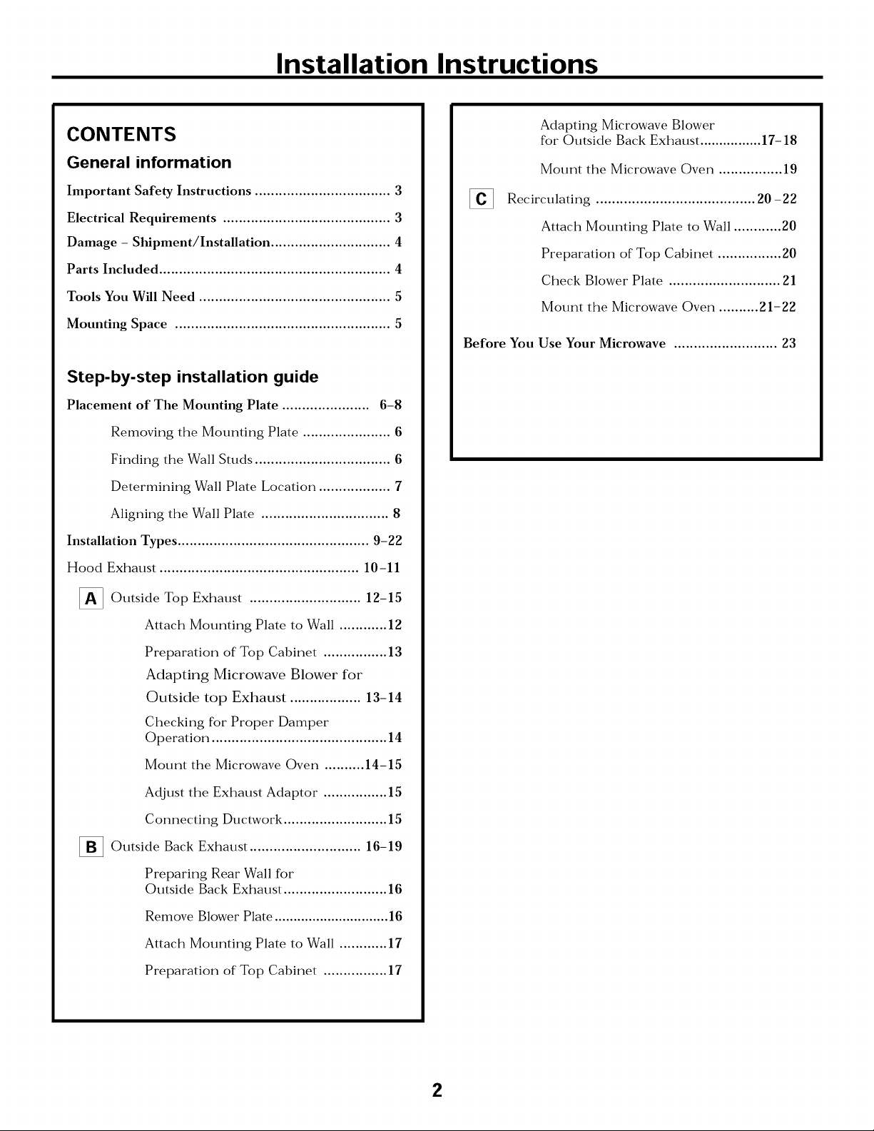
CONTENTS
General information
Important Safety Instructions .................................. 3
Electrical Requirements .......................................... 3
Damage - Shipment/Installation .............................. 4
Parts Included .......................................................... 4
Tools You Will Need ................................................ 5
Mounting Space ...................................................... 5
Step-by-step installation guide
Placement of The Mounting Plate ...................... 6-8
Removing the Mounting Plate ...................... 6
Finding the Wall Studs .................................. 6
Determining Wall Plate Location .................. 7
Aligning the Wall Plate ................................ 8
Adapting Microwave Blower
for Outside Back Exhaust ................ 17-18
Mount the Microwave Oven ................ 19
[]
Recirculating ........................................ 20 -22
Attach Mounting Plate to Wall ............ 20
Preparation of Top Cabinet ................ 20
Check Blower Plate ............................ 21
Mount the Microwave Oven .......... 21-22
Before You Use Your Microwave .......................... 23
Installation Types ................................................ 9-22
Hood Exhaust .................................................. 10-11
_ Outside Top ............................
Attach Mounting Plate to Wall ............ 12
Preparation of Top Cabinet ................ 13
Adapting Microwave Blower for
Outside top Exhaust .................. 13-14
Checking for Proper Damper
Operation ............................................ 14
Mount the Microwave Oven .......... 14-15
Adjust the Exhaust Adaptor ................ 15
Connecting Ductwork .......................... 15
1_ Outside Back Exhaust 16-19
Preparing Rear Wall for
Outside Back Exhaust .......................... 16
Remove Blower Plate .............................. 16
Attach Mounting Plate to Wall ............ 17
Exhaust 12-15
Preparation of Top Cabinet ................ 17
2
Installation Instructions
IMPORTANT SAFETY INSTRUCTIONS
This product requires a three-prong grounded outlet.
The installer" must perform a ground continuity check
on the power" outlet box before beginning the
installation to insure that the outlet box is properly
grounded. If not properly grounded, or" if the outlet
box does not meet electrical requirements noted
(under ELECTRICAL REQUIREMENTS), a qualified
electrician should be employed to correct any
deficiencies.
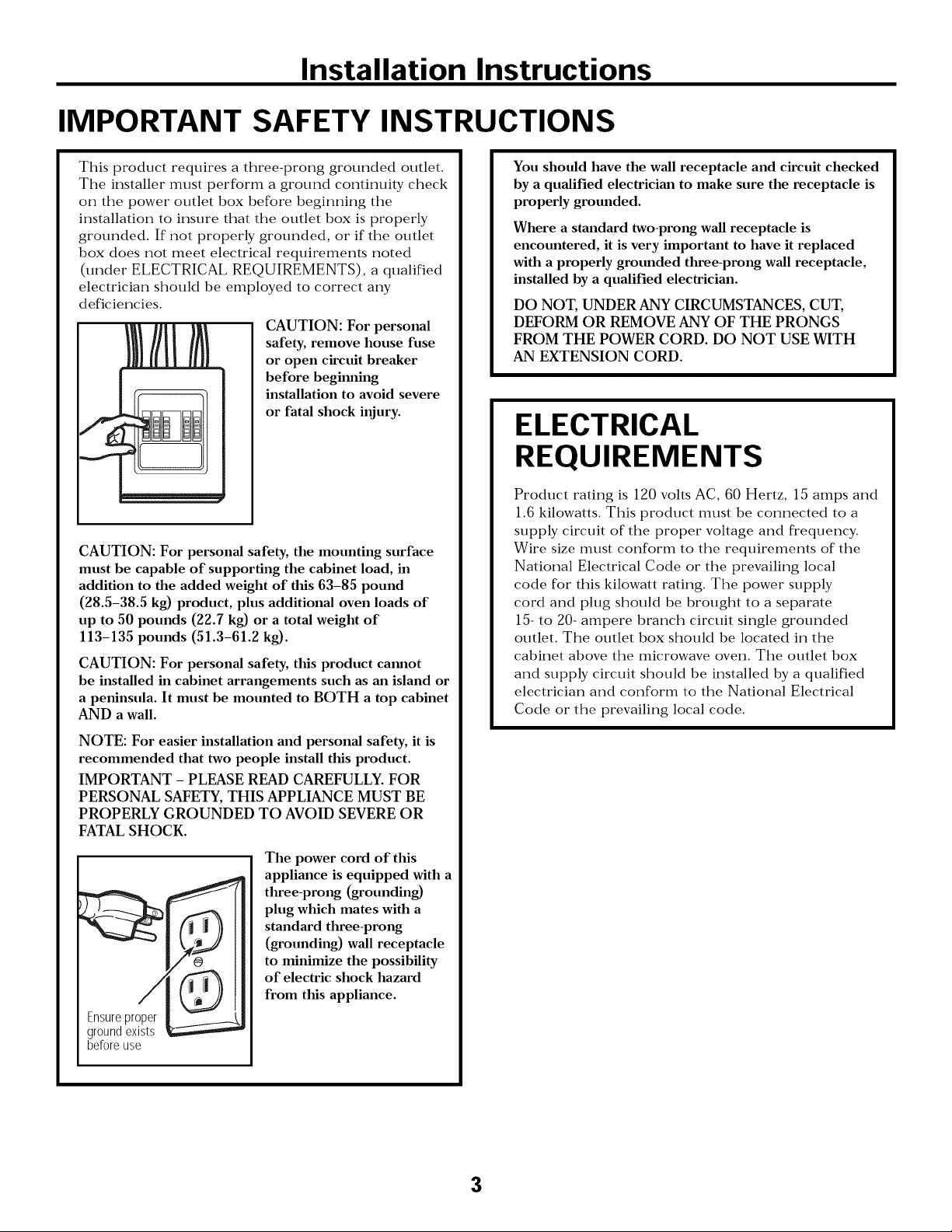
CAUTION: For personal
safety, remove house fuse
or open circuit breaker
before beginning
installation to avoid severe
or fatal shock injury.
CAUTION: For personal safety, the mounting surface
must be capable of supporting the cabinet load, in
addition to the added weight of this 63-85 pound
(28.5-38.5 kg) product, plus additional oven loads of
up to 50 pounds (22.7 kg) or a total weight of
113-135 pounds (51.3-61.2 kg).
CAUTION: For personal safety, this product cannot
be installed in cabinet arrangements such as an island or
a peninsula. It must be mounted to BOTH a top cabinet
AND a wall.
You should have the wall receptacle and circuit checked
by a qualified electrician to make sure the receptacle is
properly grounded.
Where a standard two-prong wall receptacle is
encountered, it is very important to have it replaced
with a properly grounded three-prong wall receptacle,
installed by a qualified electrician.
DO NOT, UNDER ANY CIRCUMSTANCES, CUT,
DEFORM OR REMOVE ANY OF THE PRONGS
FROM THE POWER CORD. DO NOT USE WITH
AN EXTENSION CORD.
ELECTRICAL
REQUIREMENTS
Product rating is 120 volts AC, 60 Hertz, 15 amps and
1.6 kilowatts. This product must be connected to a
supply circuit of the proper voltage and frequency.
Wire size must conform to the requirements of the
National Electrical Code or the prevailing local
code for this kilowatt rating. The power supply
cord and plug should be brought to a separate
15- to 20- ampere branch circuit single grounded
outlet. The outlet box should be located in the
cabinet above the microwave oven. The outlet box
and supply circtfit should be installed by a qualified
electrician and conform to the National Electrical
Code or the prevailing local code.
NOTE: For easier installation and personal safety, it is
recommended that two people install this product.
IMPORTANT - PLEASE READ CAREFULLY. FOR
PERSONAL SAFETY, THIS APPLIANCE MUST BE
PROPERLY GROUNDED TO AVOID SEVERE OR
FATAL SHOCK.
The power cord of this
appliance is equipped with a
three-prong (grounding)
plug which mates with a
standard three-prong
(grounding) wall receptacle
to minimize the possibility
of electric shock hazard
from this appliance.
Ensureproper
groundexists
beforeuse
3
Installation Instructions
DAMAGE--SHIPMENT/
INSTALLATION
• If the unit is damaged in shipment, return the
unit to the store in which it was bought for repair
or replacement.
• If the unit is damaged by the customer, repair or
replacement is the responsibility of the customer.
• If the unit is damaged by the installer (if other
than the customer), repair or replacement must
be made by arrangement between customer
and installer
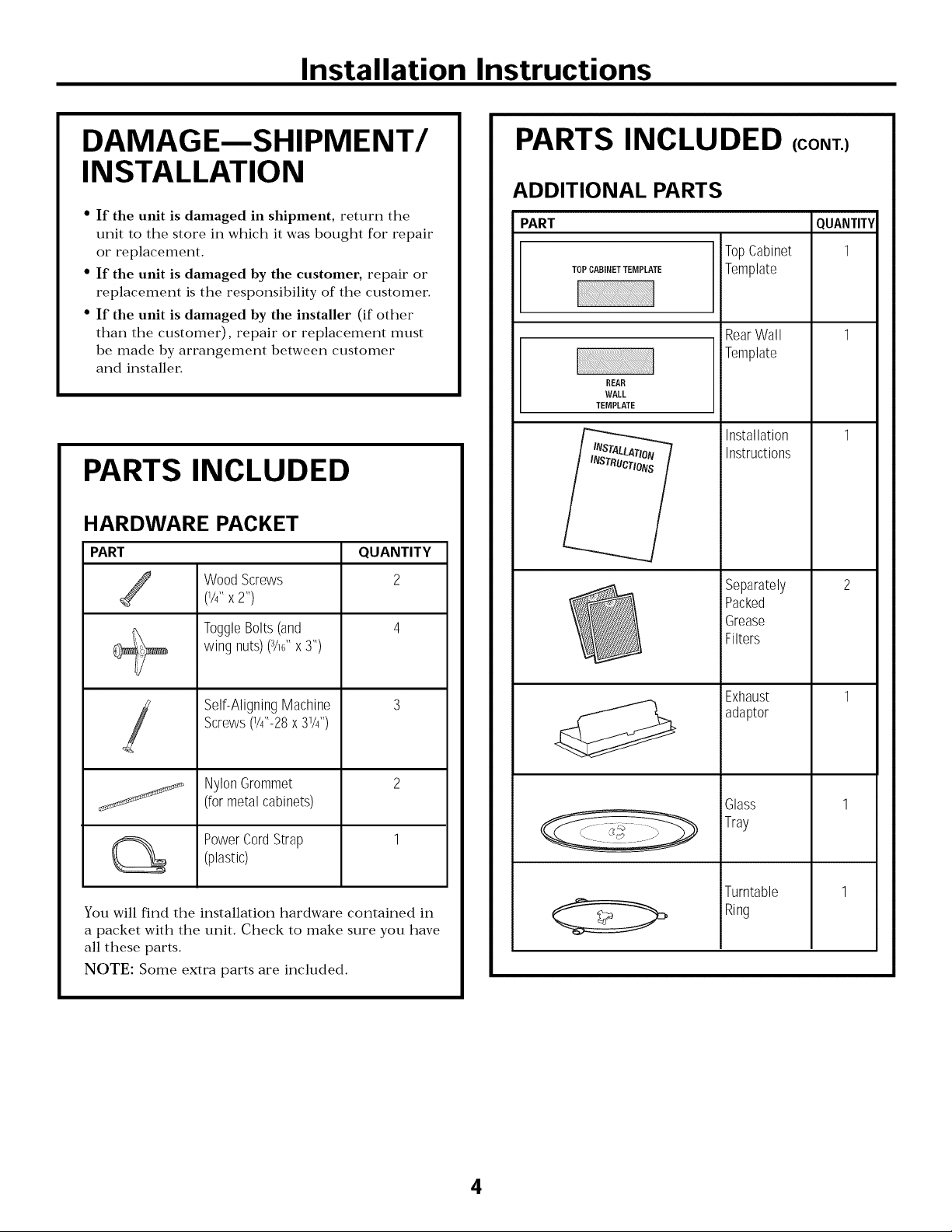
PARTS INCLUDED
HARDWARE PACKET
PART
Wood Screws
/
(1/4" X 2")
ToggleBolts(and
wingnuts)(3/16"x3")
QUANTITY
2
+
PARTS INCLUDED (CONT.)
ADDITIONAL PARTS
PART
TOPCABINETTEMPLATE
REAR
WALL
TEMPLATE
TopCabinet
Template
RearWall
Template
Installation
Instructions
Separately
Packed
Grease
Filters
QUANTITY
1
Self-AligningMachine
Screws(1/4"-28x 31/4'')
!
NylonGrommet
j_
You will find the installation hardware contained in
a packet with the unit. Check to make sure you have
all these parts.
NOTE: Some extra parts are included.
(formetalcabinets)
PowerCordStrap
(plastic)
Exhaust
adaptor
Glass
Tray
Turntable
Ring
4
Installation Instructions
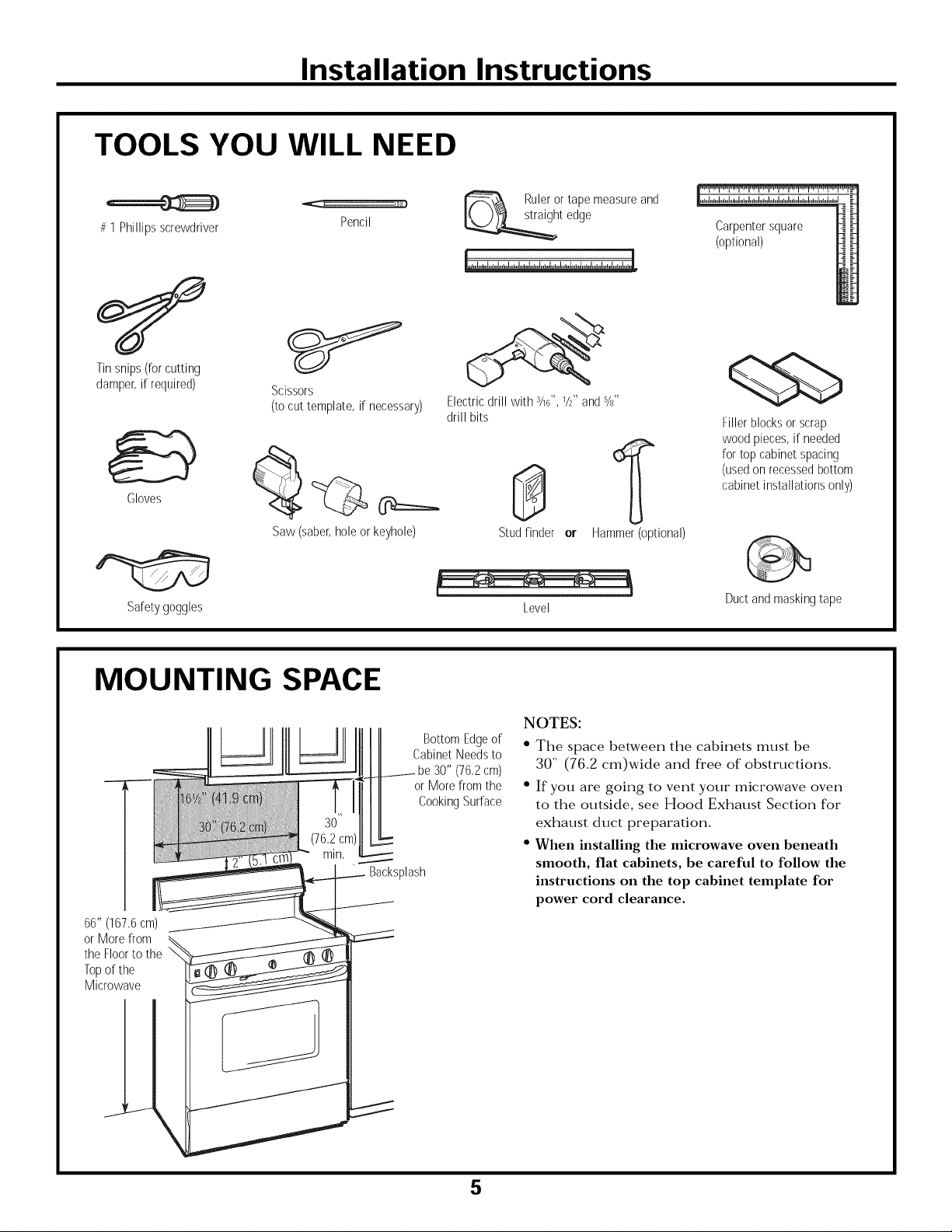
TOOLS YOU WILL NEED
# 1Phillipsscrewdriver
Tin snips (for cutting
damper, if required)
Gloves
Scissors
(to cut template, if necessary)
Pencil
Ruler or tape measure and
t edge
Electric drill with 3/16",1/2"and %"
drill bits
0
Carpentersquare
(optional)
Fillerblocksor scrap
woodpieces,if needed
fortop cabinetspacing
(usedonrecessedbottom
cabinetinstallationsonly)
Saw (saber,hole or keyhole)
Safetygoggles
MOUNTING SPACE
66" (167,6cm)
or Morefrom
the Floorto the
Topof the
Microwave
BottomEdgeof
CabinetNeedsto
be30" (76,2cm)
or Morefrom the
CookingSurface
_lash
Stud finder or
Level
Hammer (optional)
Duct and masking tape
NOTES:
• The space between the cabinets must be
30" (76.2 cm)wide and free of obstructions.
• If you are going to vent your microwave oven
to the outside, see Hood Exhaust Section for
exhaust duct preparation.
• When installing the microwave oven beneath
smooth, flat cabinets, be careful to follow the
instructions on the top cabinet template for
power cord clearance.
5
Installation Instructions
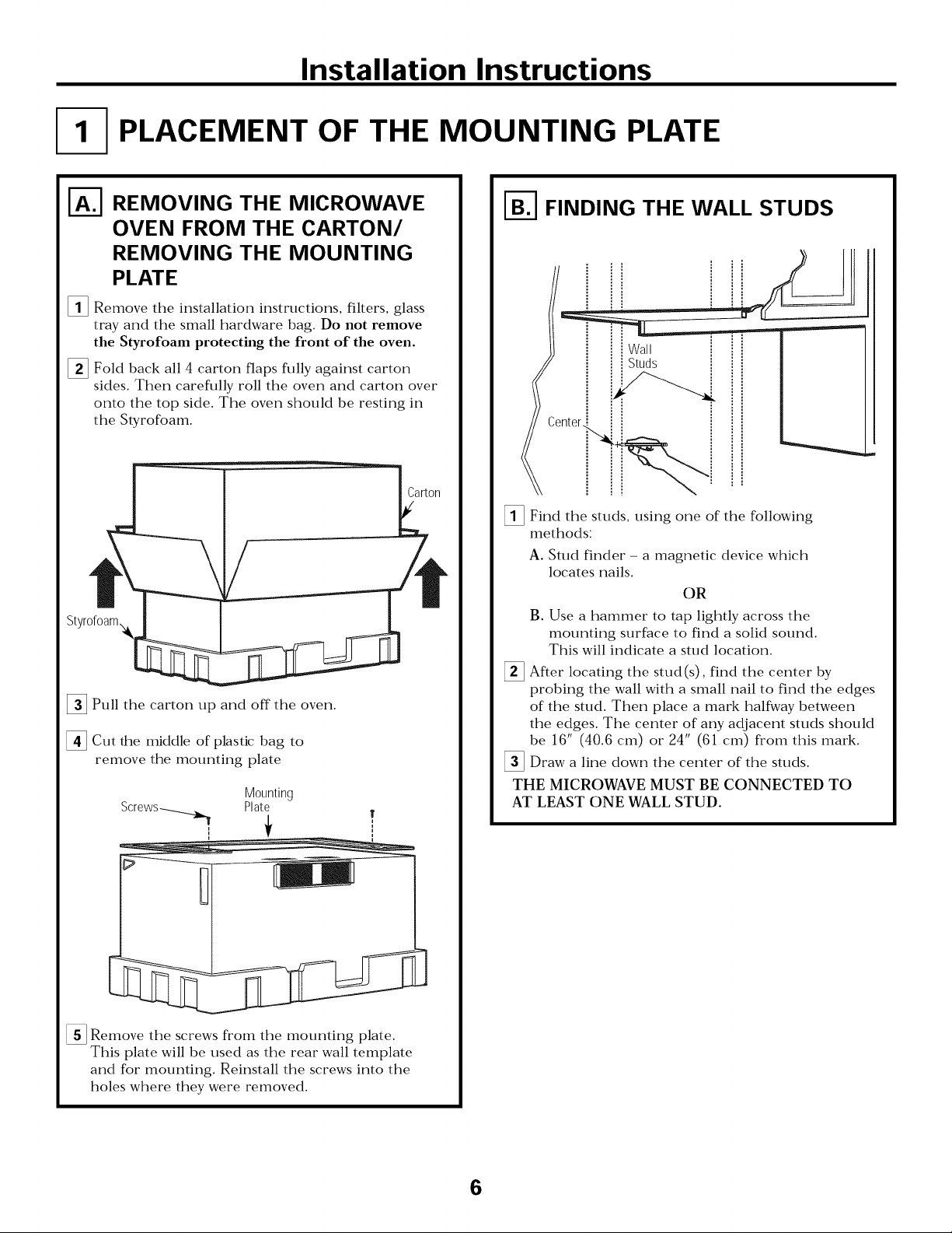
PLACEMENT OF THE MOUNTING PLATE
I-_ REMOVING THE MICROWAVE
OVEN FROM THE CARTON/
REMOVING THE MOUNTING
PLATE
[]Remove the installation instructions, filters, glass
tray and the small hardware bag. Do not remove
the Styrofoam protecting the front of the oven.
[] Fold back all 4 carton flaps fully against carton
sides. Then carefully roll the oven and carton over
onto the top side The oven should be resting in
the Styrofoam.
Styrofoam_
[]Pull the carton up and off the oven
[]Cut the middle of plastic bag to
remove the mounting plate
Screws-_ Plate
Mounting
f
I-_ FINDING THE WALL STUDS
[]Find the studs, using one of the following
methods:
A. Stud finder - a magnetic device which
locates nails.
OR
B. Use a hammer to tap lightly across the
mounting surface to find a solid sound.
This will indicate a stud location
[] After locating the stud(s), find the center by
probing the wall with a small nail to find the edges
of the stud. Then place a mark halfway between
the edges. The center of any adjacent studs should
be 16" (40.6 cm) or 24" (61 cm) from this mark.
[]Draw a line down the center of the studs.
THE MICROWAVE MUST BE CONNECTED TO
AT LEAST ONE WALL STUD.
[]Remove the screws from the mounting plate.
This plate will be used as the rear wall template
and for mounting. Reinstall the screws into the
holes where they were removed.
6
Installation Instructions
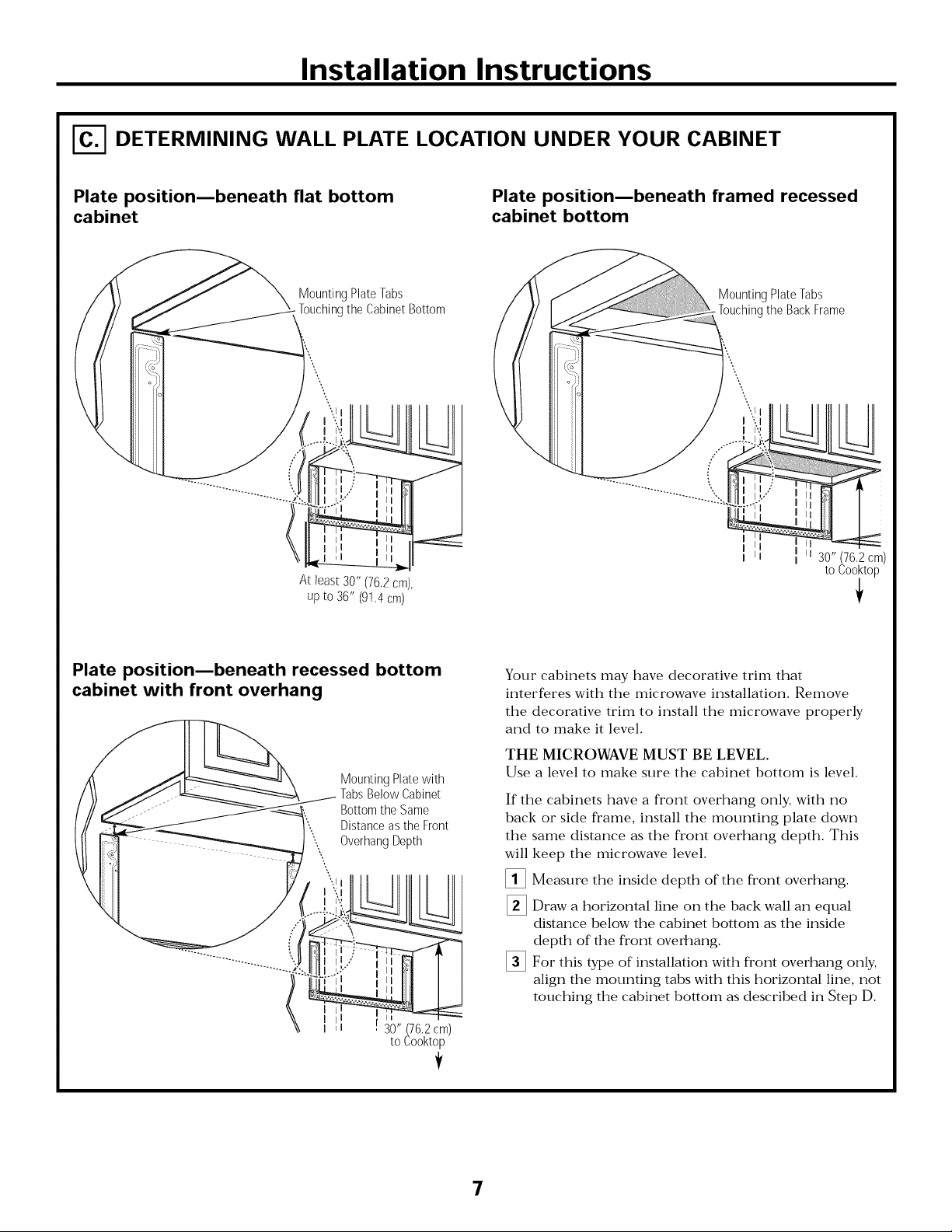
DETERMINING WALL PLATE LOCATION UNDER YOUR CABINET
Plate positionmbeneath flat bottom
cabinet
MountingPlateTabs
Touchingthe CabinetBottom
At least30" (76.2cm),
upto 36" (9!.4 cm)
Plate positionmbeneath framed recessed
cabinet bottom
MountingPlateTabs
.Touchingthe BackFrame
I
I ii 30" (76,2 cm)
to Cooktop
i
Plate position_beneath recessed bottom
cabinet with front overhang
Mounting Plate with
Tabs Below Cabinet
Bottom the Same
Distance as the Front
Overhang Depth
30" (76,2 cm)
to Cooktop
Your cabinets may have decorative trim that
interferes with the microwave installation. Remove
the decorative trim to install the microwave properly
and to make it level.
THE MICROWAVE MUST BE LEVEL.
Use a level to make sure the cabinet bottom is level.
If the cabinets have a front overhang only, with no
back or side frame, install the mounting plate down
the same distance as the front overhang depth. This
will
keep the microwave level.
[]
Measure the inside depth of the front overhang.
%
Draw a horizontal line on the back wall an equal
distance below the cabinet bottom as the inside
depth of the front overhang.
%
For this type of installation with front overhang only,
align the mounting tabs with this horizontal line, not
touching the cabinet bottom as described in Step D.
!
7
Installation Instructions
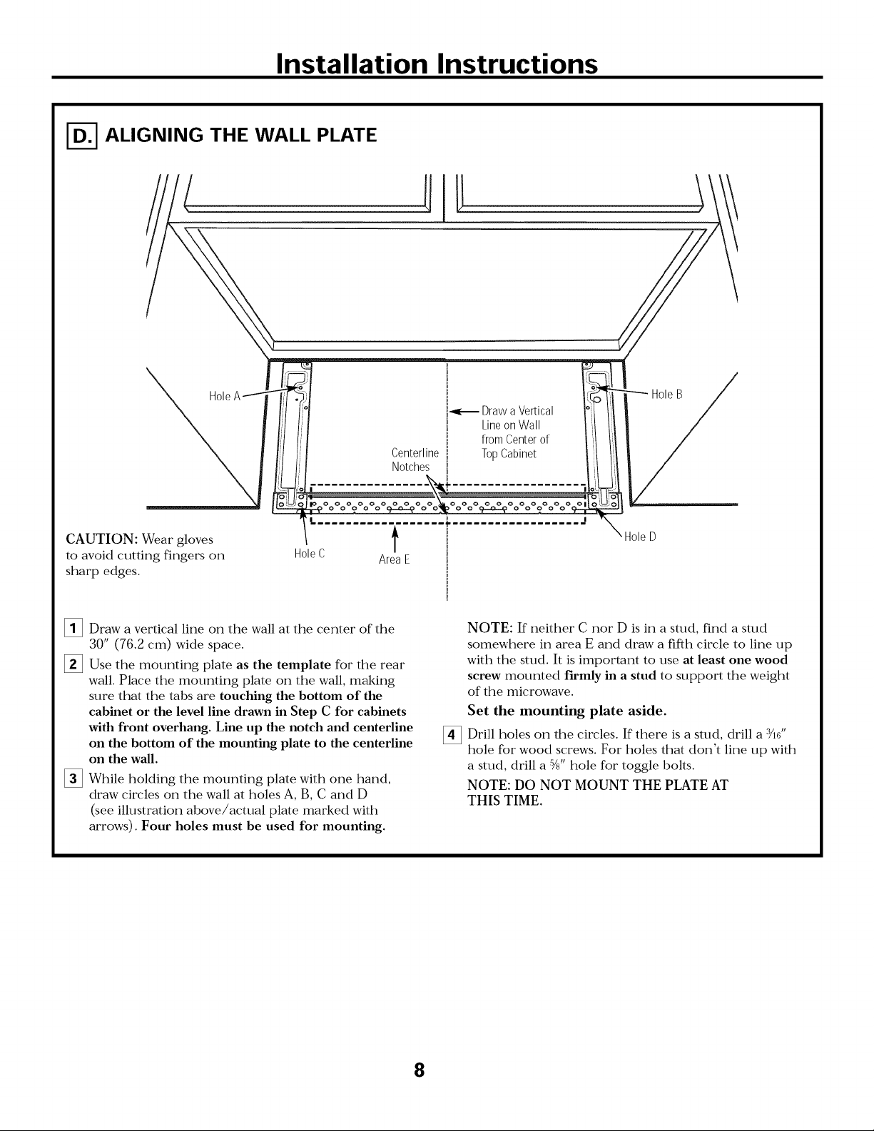
ALIGNING THE WALL PLATE
. s
[_-_ Draw a Vertical °:t
[ Line on Wall _I
l from Center of ,:1
Centerline [ Top Cabinet i!t
Notches [ J:l
I
i
-_? o o ? o o cF--o---_o c _ o o Or---o-_o o o_
CAUTION: Wear gloves
to avoid cutting fingers on
sharp edges.
[]Draw a vertical line on the wall at the center of the
30" (76.2 cm) wide space.
[]Use the mounting plate as the template for the rear
wall. Place the mounting plate on the wall, making
sure that the tabs are touching the bottom of the
cabinet or the level line drawn in Step C for cabinets
with front overhang. Line up the notch and centerline
on the bottom of the mounting plate to the centerline
on the wall.
[]While holding the mounting plate with one hand,
draw circles on the wall at holes A, B, C and D
(see illustration above/actual plate marked with
arrows). Four holes must be used for mounting.
Hole C Area E
I ,
\ Hole D
I
I
NOTE: If neither C nor D is in a stud, find a stud
somewhere in area E and draw a fifth circle to line up
with the stud. It is important to use at least one wood
screw mounted firmly in a stud to support the weight
of the microwave.
Set the mounting plate aside.
Drill holes on the circles. If there is a stud, drill a 3/16'1
[]
hole for wood screws. For holes that don't line up with
a stud, drill a 5/8" hole for toggle bolts.
NOTE: DO NOT MOUNT THE PLATE AT
THIS TIME.
8
 Loading...