

Page 1
1. ANALYSER LAYOUT AND FEATURES
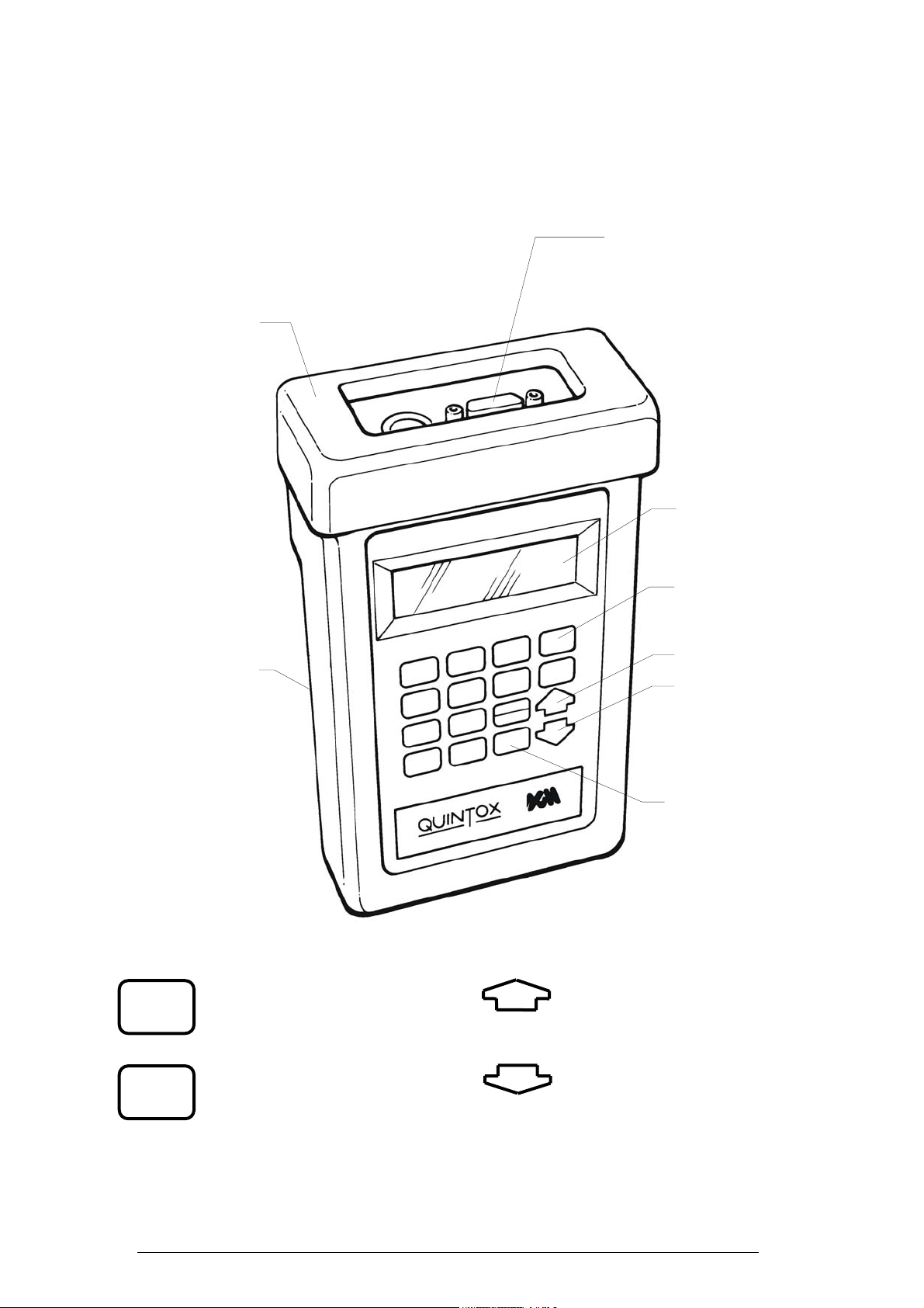
1.1 Handset Features
Remote lead socket
(15 pin D type)
Also used for
downloading data
Rubber boot
to PC
4 line display
Battery
Compartment
(back)
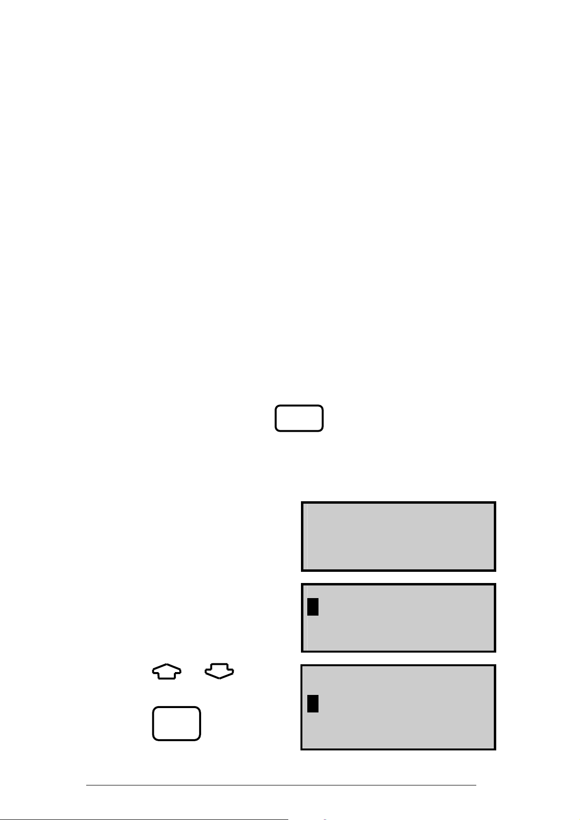
Commonly used keys
ON/OFF UP
ON
OFF
ENTER & SET/CAL
SET/CAL
ENTER
Accepts parameters
Enters values
ON/OFF Key
UP key
DOWN key
ENTER/SETCAL
keys
Pages up through screens
Scrolls up through options, ie Fuel
DOWN
Pages down through screens
Scrolls down through options
KM9106 Operators Manual
1
Page 2
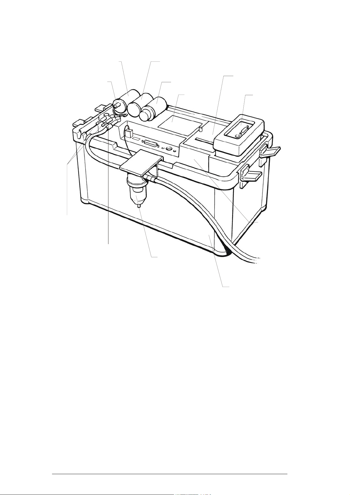
1.2 Analyser Layout
Oxygen Sensor Filter Bridge
Connection lead
for Oxygen
sensor
or Sulphur Filter
Particle Filter
Battery
enclosure
Printer unit
Handset
(stored in
pocket)
Dual
pressure ports
Water trap
connection
Water trap
located on
side of instrument
Accessory
storage
space
(leads/water
trap etc.)
Instrument case
2
KM9106 Operators Manual
Page 3
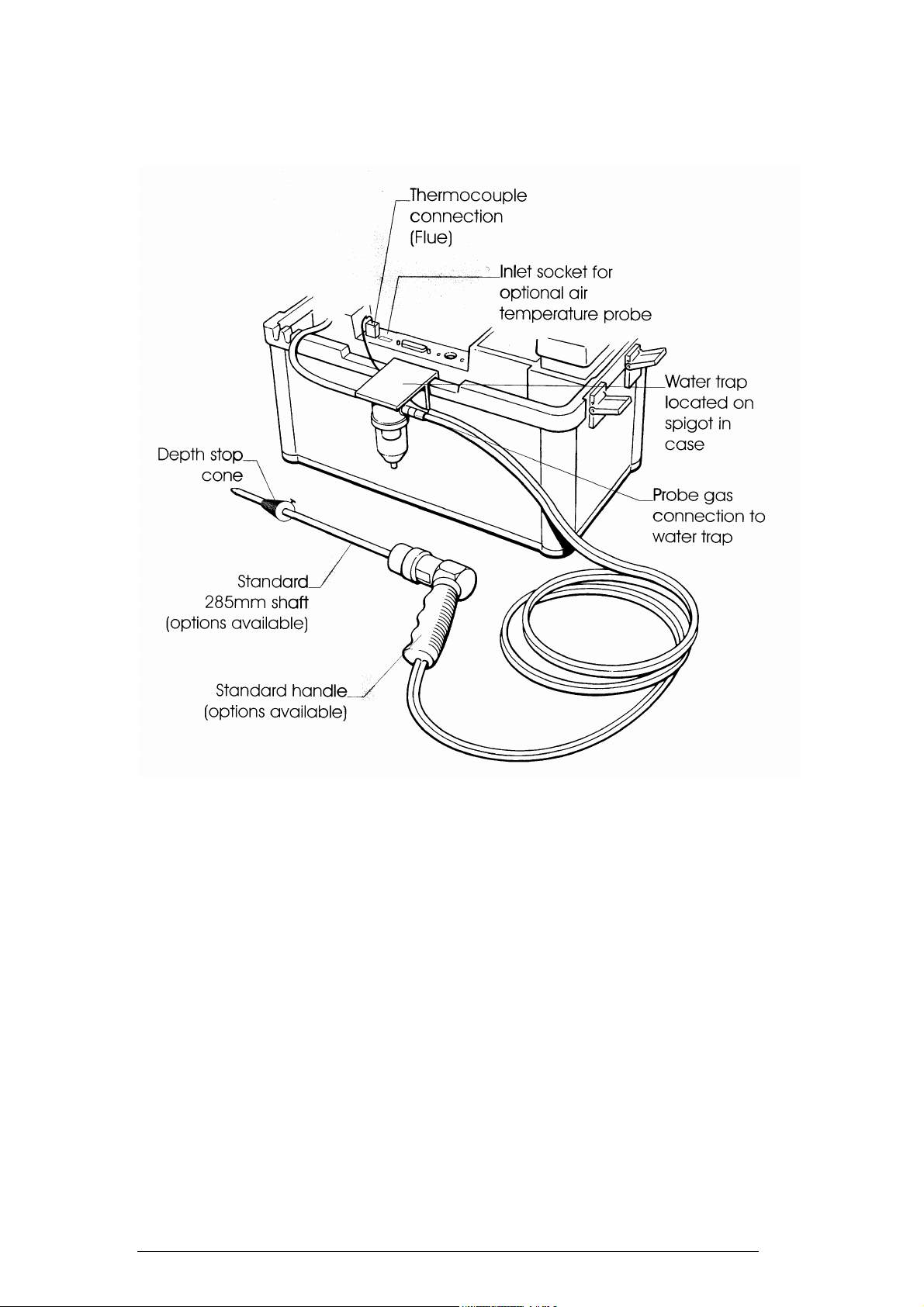
1.3 Standard Probe Configuration
KM9106 Operators Manual
3
Page 4
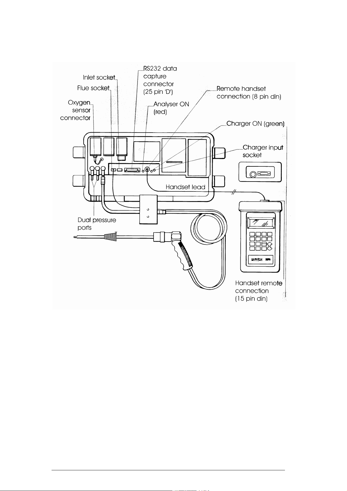
1.4 Analyser Connections
4
KM9106 Operators Manual
Page 5

2. SAFETY WARNING
This analyser extracts combustion gases that may be toxic in relatively low
concentrations. These gases are exhausted from the bottom of the instrument. This
instrument must only be used in well ventilated locations. It must only be used by
trained and competent persons after due consideration of all the potential hazards.
3. FIRST TIME USE
Charge the battery for 12 hours, following this an overnight charge should be
sufficient for an average 8 hour day.
Whilst charging the green LED will be illuminated, the LED will flash when the
battery is fully charged.
Check that you have all the items you have ordered.
We offer a wide choice of probes which are not supplied as standard and must be
ordered as a separate item.
Take time to read this manual fully.
TIP: Take a look at the Spare Parts list and order some replacement filters
and paper rolls now.
When using the analyser for the first time you have the following under your control
:-
PARAMETER SECTION
Display Contrast 5.4
Backlight 5.4
Language 6.4
Line Rejection for mains frequency 6.4
Gas Measurement Scale 6.4
Temperature scale 6.4
Pressure scale 6.4
Reference oxygen 6.4
Time and date 6.1
KM9106 Operators Manual
5
Page 6

Printed header name and telephone number 7.1
6
KM9106 Operators Manual
Page 7
4. NORMAL START UP SEQUENCE
4.1 Every Time You Use The Analyser
BEFORE SWITCH-ON CHECK THAT:
the Oxygen sensor is connected
the particle filter is not dirty
the sulphur filter is fitted for heavy oil or coal
the water trap and probe line are empty of water
all hose connections, etc, are properly made
the paper roll is fitted
the probe is sampling ambient FRESH air
the water trap is vertical
the flue temperature is connected
the instrument is placed on a clean, flat, level surface
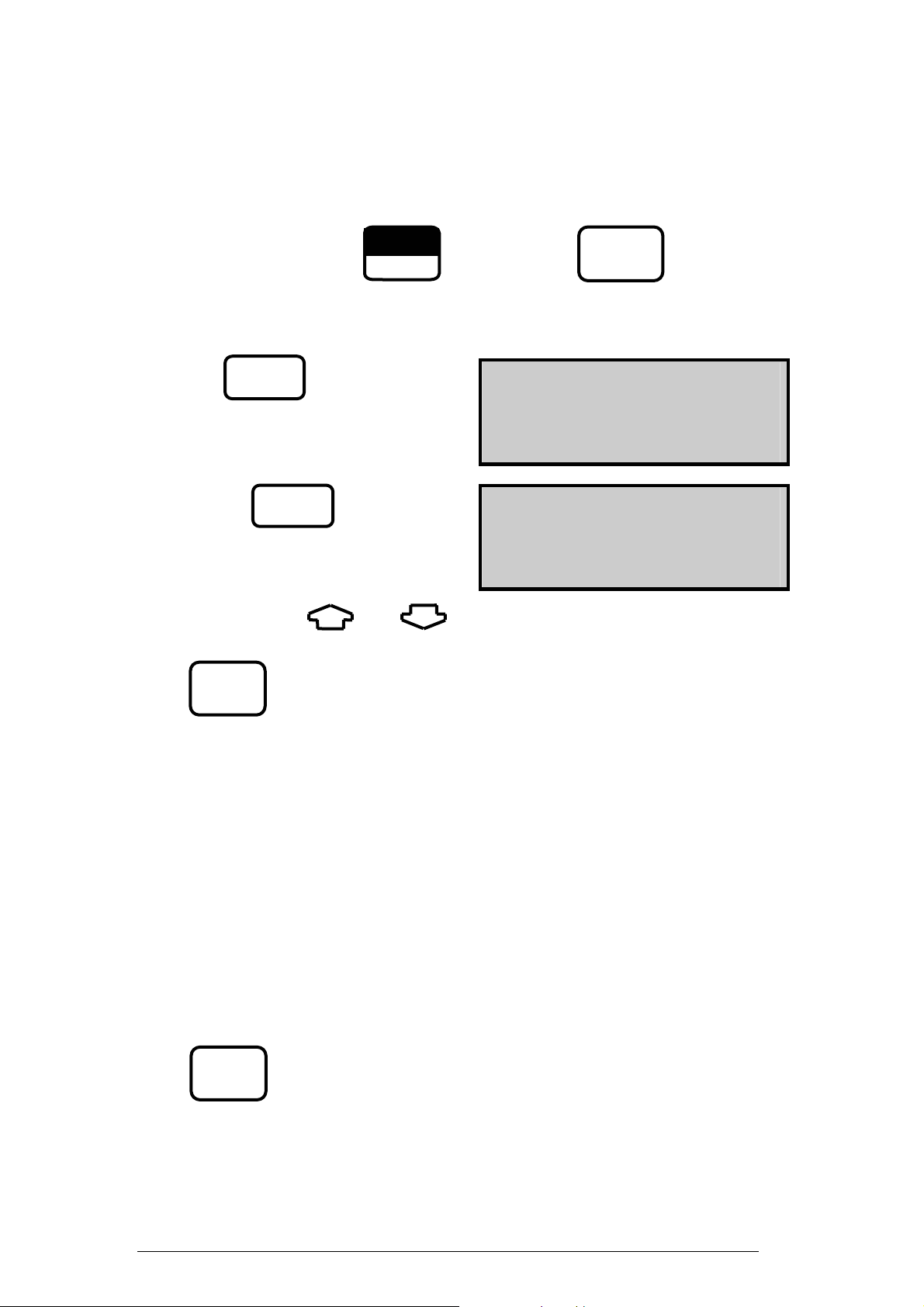
Switch ON the instrument by pressing
4.2 Automatic Calibration
ON
During this sequence the analyser pumps fresh air into the sensors to allow toxic
sensors to be set to zero and the Oxygen sensor to be set to 20.9 %.
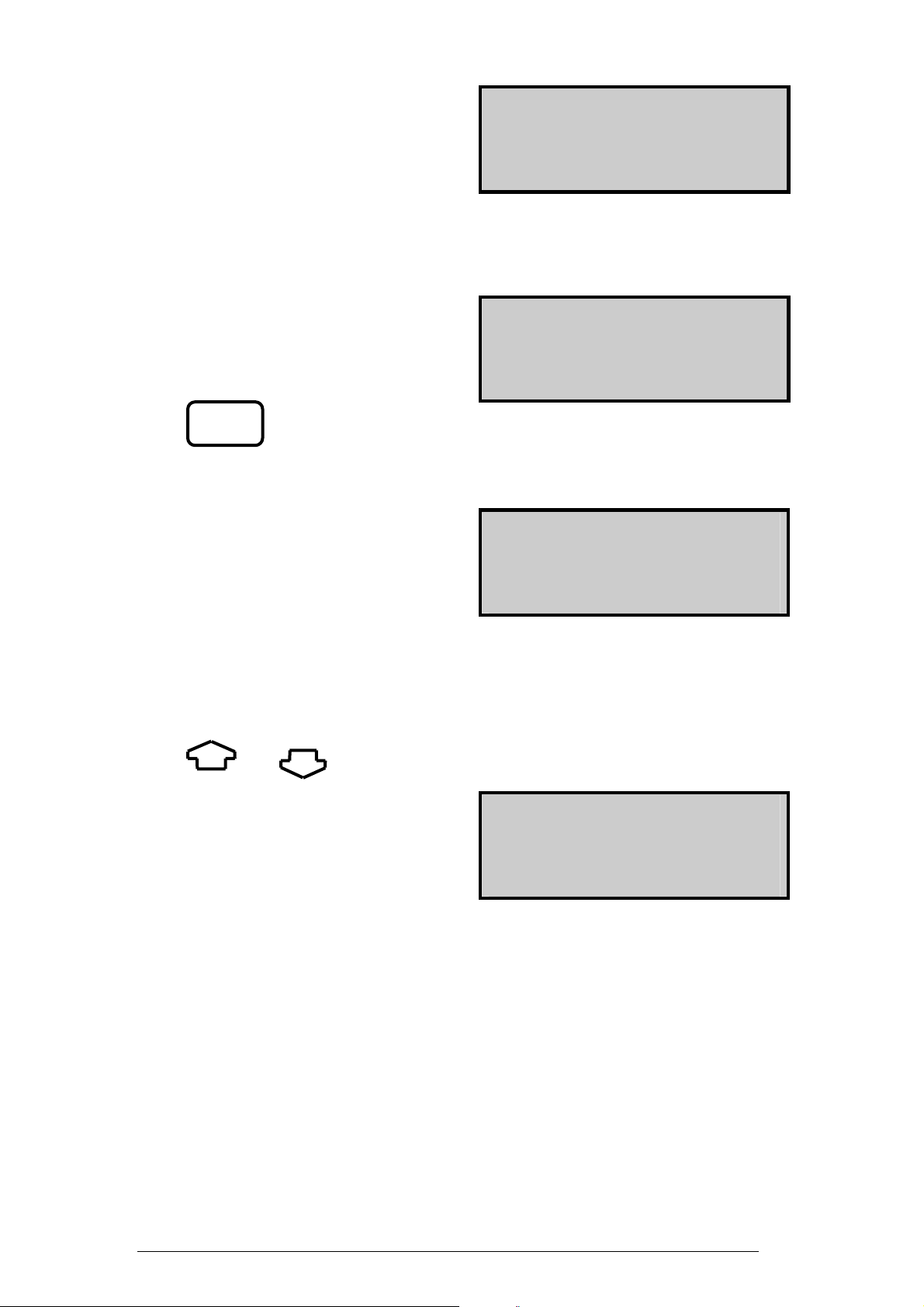
After switch-on the analyser will
briefly display the Kane logo and
telephone numbers:-
777 KANE-MAY 777
TEL +44 (0) 1707 375550
FAX +44 (0) 1707 393277
Followed by the logger menu screen :-
9 9 SELECT FUNCTION 9 9
1
. . LOGGER CONTROL
2 . . QUINTOX CONTROL
Use the and keys to
position the cursor over 2 . .Quintox
Control.
Press to access Quintox
Control
ENTER
9 9 SELECT FUNCTION 9 9
1 . . LOGGER CONTROL
2
. . QUINTOX CONTROL
KM9106 Operators Manual
7
Page 8
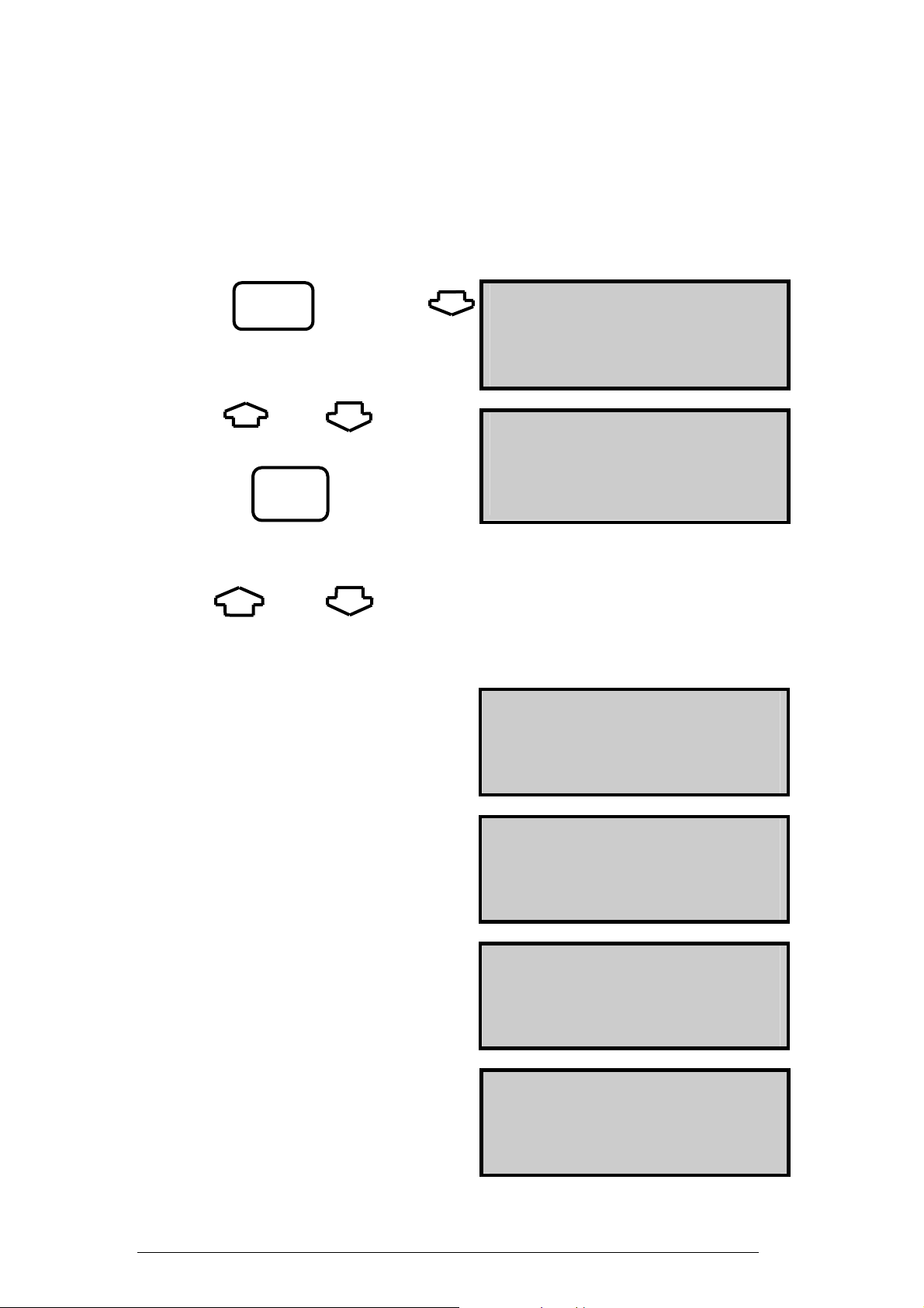
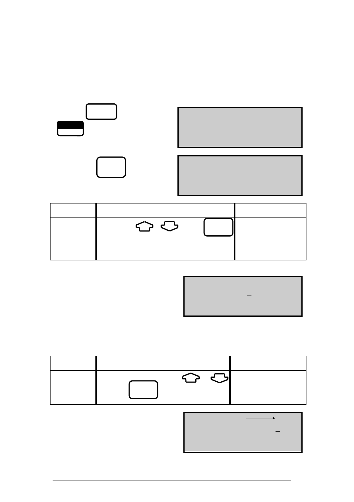
And show the countdown screen :-
-- -- -- -- -- -- -- -- -- -- -- -- --
9 CALIBRATING 9 9
300
-- -- -- -- -- -- -- -- -- -- -- -- --
The display will countdown from 300 to zero in one second steps. If the analyser has
been used recently it may complete automatic calibration in less than 300 seconds
otherwise it will count to zero.
Once the calibration sequence is
complete an audible beep will be heard
and will show the selected fuel on the
following display:-
Press
This zeros the toxic sensor and sets Oxygen to 20.9%. The next screen is the MAIN
DISPLAY of the analyser:-
ENTER
-- -- -- -- -- -- -- -- -- -- -- -- -NATURAL GAS
PRESS ENTER KEY
-- -- -- -- -- -- -- -- -- -- -- -- --
DATE . . . 07-08-96
TIME . . . 12:31:35
INSTABILITY 0
BATTERY % . . 54
MAIN DISPLAY
NOTE : It is advisable to repeat Oxygen Calibration every 2 hours for maximum
accuracy.
Use and to change the display.
NETT C . . . . 0.0
O2 % . . . 20.9
CO ppm . . . 0000
EFF (G) % . . . 0.0
All parameters are detailed in Appendix A - MAIN DISPLAY PARAMETERS.
8
KM9106 Operators Manual
Page 9
4.3 Main Displays
The main display can be changed to show the following :-
• Page Mode displays 4 lines of data in set format, each page is predefined.
• Line scroll mode allows you to customise the display with the data you require.
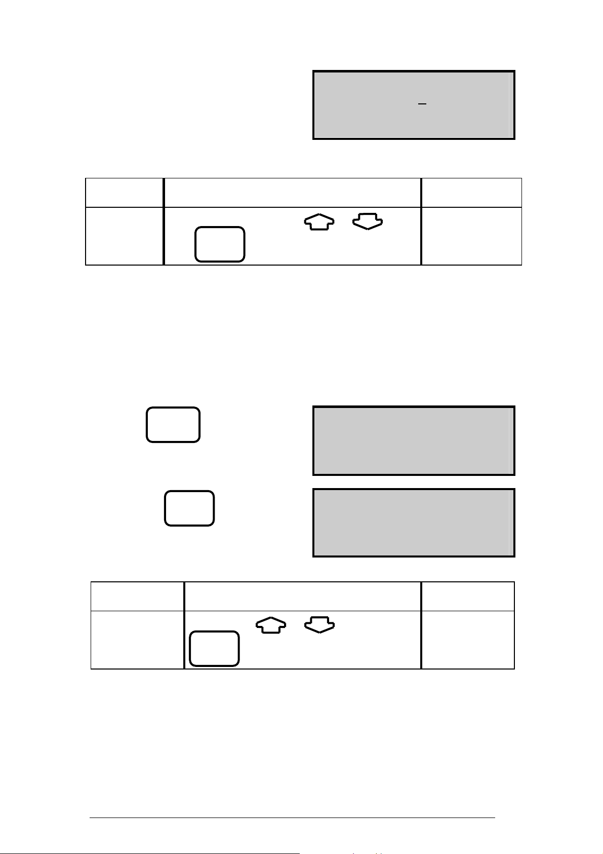
To change between the different modes :-
Press followed by
SET/CAL
PAGE MODE
SET
The and keys change
between Page and Line Scroll Modes
Press to select
ENTER
4.3.1 Page Mode
LINE SCROLL MODE
SET
Use the and keys to change the information displayed on the
screen. The following are a number of the pages available. Other parameters on other
screens are detailed in Appendix A.
NETT C . . . 0.0
O2 % . . . 20.9
CO ppm . . 0000
EFF (G) % . . . 0.0
CO2 % . . . 0.0
FLUE C . . . 0.0
INLT NOT FITTED
AMBIENT C . . . 21
CO/CO2 R . . 0.0001
P INDEX % . . . 0.01
XAIR % . . . 0.0
Prs mbar 0.00
This screen only shows readings if optional
sensors are fitted. In this instance the SO2
sensor is NOT FITTED.
NO ppm . . 0000
NO2 ppm . . 0000
NOx ppm . . 0000
SO2 NOT FITTED
KM9106 Operators Manual
9
Page 10
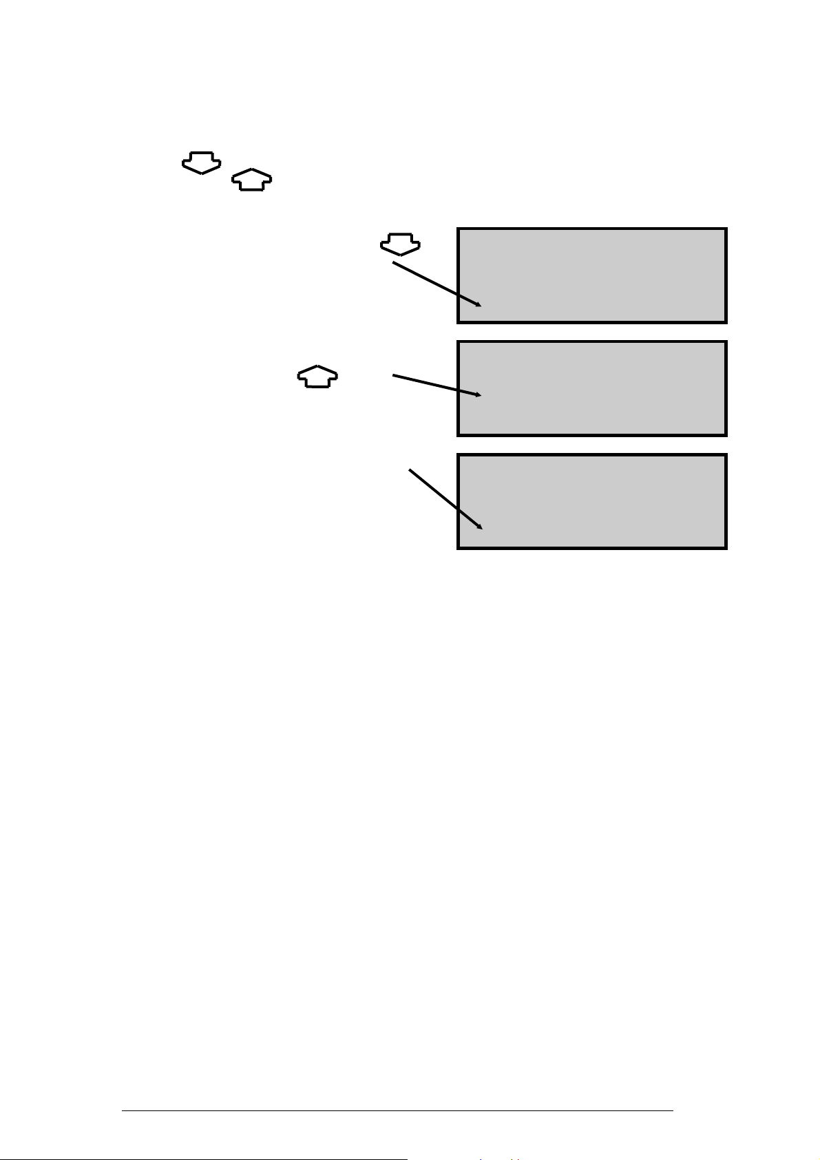
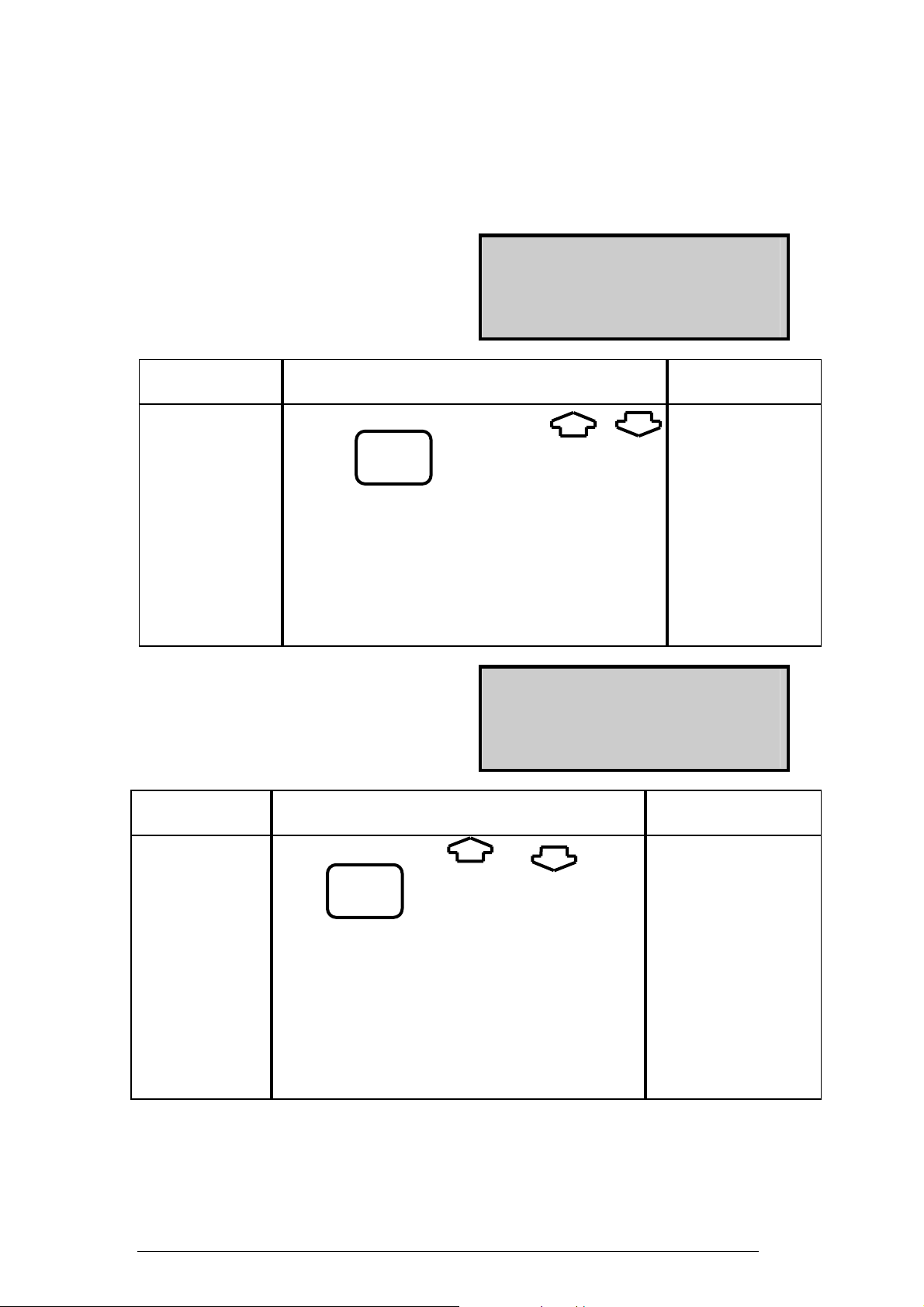
4.3.2 Line Scroll Mode
Line scroll mode allows you to customise the display.
Use the key to change the bottom line of the display. Once the correct line is
displayed press to confirm and move the line up. Select the next parameter and
repeat until all lines display the desired parameters.
Change bottom line using
NETT C . . . 0.0
O2 % . . . 20.9
CO ppm . . 0000
CO2 % . . . 0.0
to select and move
parameter up
O2 % . . . 20.9
CO ppm . . 0000
CO2 % . . . 0.0
CO2 % . . . 0.0
Select next parameter.
Repeat above until
display reads desired data
O2 % . . . 20.9
CO ppm . . 0000
CO2 % . . . 0.0
CO/CO2 R . . 0.0001
10
KM9106 Operators Manual
Page 11
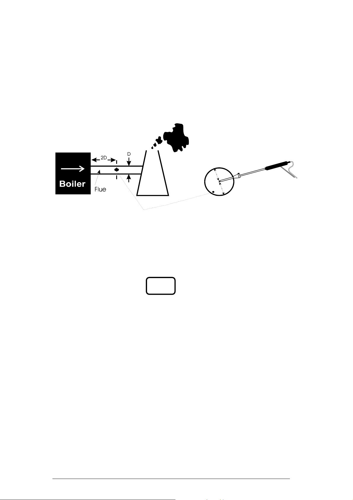
4.4 Sampling the Flue Gas
Once the automatic calibration procedure has been completed and the specific fuel has
been selected the probe can be inserted into the desired sampling point.
It is recommended that the sampling point be located at least two flue diameters
downstream of any bend and that the probe tip is in the centre of the flue (this is
normally the point of the hottest temperature). With balanced flues and other domestic
units the probe should be positioned far enough into the flue so that no air can ‘back
flush’ into the probe.
The probe depth stop cone provided with the instrument allows the probe to be used
in holes whose diameters range from 8 mm to 21 mm (5/16 to 4/5 inch).
The standard probe is rated at 650°C/1202°F. Temperatures of up to 1100°C/2012°F
can be accommodated using an optional high temperature probe.
TIP: To conserve battery power, switch off the pump when you are not taking a
measurement. Use the key to turn the pump ON and OFF.
PUMP
KM9106 Operators Manual
11
Page 12
4.5 Taking a Pressure Reading
With the optional pressure module fitted a flue draught measurement can be made at
any time.
Connect the standard probe to the appropriate pressure sensor inlet and place the
probe in the flue.
The pressure reading will be displayed :-
CO/CO2 R . . 0.0001
P INDEX % . . . 0.01
XAIR % . . . 0.0
Prs mbar 0.00
NOTE: Care must be taken to connect the probe to the correct port as the pressure
will be displayed in reverse i.e. a positive pressure rather than negative
draught.
To perform a combustion test and display draught pressure at the same time a special
probe is required. Contact Kane International or Authorised Distributor for details.
Two pressure ports are provided on the instrument for use with a Pitot tube. Contact
Kane International Ltd. for details of this probe and its availability.
4.6 Regular Checks During Sampling
Care must be taken at all times not to exceed the analyser’s operating specification. In
particular ensure the following :-
• Do not exceed the maximum temperature of the flue probe.
• The analyser’s internal temperature does not exceed normal operating range,
typically 0-40°C.
• DO NOT PLACE THE ANALYSER ON A HOT SURFACE.
• The water trap is vertical at all times. Water condenses in the probe line and can
quickly fill the water trap when the probe is moved. Take care and watch the water
trap closely.
• The in-line particle filter is clean and does not become blocked.
12
KM9106 Operators Manual
Page 13

4.7 Normal Shutdown Sequence
DO THIS EVERY TIME YOU USE THE ANALYSER.
Remove the probe from the flue - TAKE CARE ! THE PROBE WILL BE HOT -
and allow it to cool naturally. Do not immerse the probe in water as this will be drawn
into the analyser and damage the pump and sensors.
Once the probe is removed from the flue, the oxygen reading 20.9% and the CO
reading is zero press and the analyser will switch off.
OFF
Check the water trap and probe tubes for water before packing away.
4.8 Electromagnetic Compatibility
The European Council Directive 89/336/EEC requires that electronic equipment does
not generate electromagnetic disturbances that exceed defined levels and has an
adequate level of immunity to enable it to be operated as intended. The specific
standards applicable to this product are detailed in the appendices.
Since there are many electrical products in use that pre-date this Directive and may
emit electromagnetic radiation in excess of the standards defined in the Directive
there may be occasions where it would be appropriate to check the analyser prior to
use. The following procedure should be adopted:
Go through the normal start up sequence in the location where the equipment is to be
used.
Switch on all localised electrical equipment that might be capable of causing
interference.
Check that all readings are as expected. (A level of disturbance in the readings is
acceptable). If not adjust the position of the instrument to minimise interference or
switch off, if possible, the offending equipment for the duration of the test.
N.B. Maximum cable lengths must be less than 3 metres.
At the time of writing this manual (January 1997) Kane International Ltd is not aware
of any field based situation where such interference has ever occurred and this advice
is only given to satisfy the requirements of the Directive.
4.9 HC104 Module
With this module fitted and working the CO2 value is always the measured value not
the calculated value. The handset display and print out indicate that the CO2 value is
a measured value by showing CO2m. If the module is not fitted, the KM9106
automatically defaults to calculated CO2. If during start up calibration a fault is
detected in the CO2 module, the instrument will default to calculated. If the
instrument displays CO2m FAULT during operation, by switching OFF and then ON,
the instrument will default to calculated CO2.
KM9106 Operators Manual
13
Page 14
5. USING THE KEYPAD
5.1 Basic Operation
Basic operation of the keypad to change the display in PAGE and LINE SCROLL
mode is detailed section 4.3. These modes give you the facility to perform the
following :-
• Page Mode displays 4 lines of data in set format, each page is predefined.
• Line scroll mode allows you to customise the display with the data you require.
5.2 QUICK key operation
To allow parameters to be viewed quickly Quintox has a number of QUICK keys.
Many of these keys have two functions.
To select an LOWER PARAMETER
parameter simply press the key i.e.
to display CO2 and three other
CO
2
values
To select a UPPER PARAMETER
parameter press the UPPER FUNCTION
key
Followed by the UPPER PARAMETER
you require parameter key i.e.
NO2
to display NO2 and three
other values
CO2 % . . . 20.9
CO ppm . . . 0000
NETT C . . . . 0.0
XAIR O2 > 20%
-- -- -- -- -- -- -- -- -- -- -- -- -UPPER FUNCTION
-- -- -- -- -- -- -- -- -- -- -- -- --
NO2 ppm . . . . . 0
NO ppm . . . . . 0
NETT C . . . . 0.0
CO ppm . . . . . 0
Other QUICK keys are detailed below :-
LOWER PARAMETER KEYS
NETT to display Nett temperature plus O
FLUE to display Flue temperature plus Ambient, O2 and Prs.
INLET to display Inlet temperature plus Ambient, O2 and Flue
O
2
to display Oxygen reading plus CO, CO2 and Nett
CO2 to display Carbon Dioxide calculation or reading CO, Nett and XAIR
CO to display Carbon Monoxide plus Nett, O2 and CO2
AUX to display AUX1 and CxHy readings plus Nett and CO
FUEL to display chosen fuel and its parameters
EFF to display Gross efficiency plus O2 and CO
14
KM9106 Operators Manual
, CO and Eff.
2
Page 15
UPPER PARAMETER KEYS
ALWAYS Press UPPER FUNCTION first then
SCALE to display Scaling setup parameters
AMBIENT to display ambient temperature plus sensor, Flue and Inlet
SO2 to display Sulphur Dioxide reading plus Nett, O2 and CO
NO2 to display Nitrogen Dioxide reading plus NO, Nett and CO
NO to display Nitric Oxide reading plus NOx, Nett and CO
NO
X
PRESSURE to display the pressure reading plus Flue, Nett and O2
LOSSES to display all four losses
λ to display Excess Air plus CO, Eff and CO2.
All measured and calculated values are detailed in Appendix A - Main Display
Parameters.
to display the Oxides of Nitrogen reading plus NO, CO and Nett
5.3 DISPLAY HOLD
The display hold function allows you to freeze values on the instrument allowing
them to be viewed or printed. No measurements are taken once this function has been
activated. This feature gives the following benefits :-
• Data can be viewed at a particular point in the boiler tuning process.
• Multiple printouts may be obtained of the same data.
• Scales can be changed between printouts giving different units. i.e. ppm and mg/m3
TO TOGGLE DISPLAY HOLD
Press UPPER FUNCTION followed by
# Indicates the display is held.
# NETT C . . . 0.0 #
# O2 % . . . 20.9 #
# CO ppm . . 0000 #
# EFF (G) % . . . 0.0 #
In this function only the battery level will be updated and all other parameters are
frozen. This does not apply when AUTOPRINT is ON, the time and date are also
updated in this mode.
KM9106 Operators Manual
15
Page 16
5.4 DISPLAY BACKLIGHT AND CONTRAST
The display contrast can be adjusted to suit different lighting conditions and the
backlight can be switched on or off.
TO TOGGLE THE BACKLIGHT ON /OFF
Press UPPER FUNCTION followed by
CONTRAST
TO SET THE CONTRAST
Press the followed by
UPPER FUNCTION key
SET/CAL
-- -- -- -- -- -- -- -- -- -- -- -- -UPPER FUNCTION
SET
-- -- -- -- -- -- -- -- -- -- -- -- --
Pressing the key displays
CONTRAST
SET
CONTRAST
Hold down either the or key and release once the desired level is
set.
Press to confirm setting.
ENTER
NOTE: The screen may flip from all dark to blank very quickly. Do not panic this
is normal - keep pressing the same key until the desired level is displayed.
TIP: If for any reason the display is not visible at switch on, simply
disconnect the handset for a few seconds and re-connect. Then reset
the display contrast as detailed above.
5.5 PUMP
The Pump can be toggled on or off from the handset.
TO TOGGLE THE PUMP ON /OFF
Press
PUMP
TIP: When the pump is switched off the O
reading will go down as the
2
oxygen sensor consumes the oxygen in its housing!
16
KM9106 Operators Manual
Page 17

6. USER SELECTABLE SETTING
The following features are under your control at any time and can be changed as
detailed later in this section.
Time and date
Fuel type
Efficiency
Language
Line Rejection
Gas Scale
ppm(n) or mg/m
Compensation
Temperature scale
Pressure scale
Reference oxygen
NOx Calculation
temperature
Inlet
Oxygen calibration
Toxic sensor zero
Day/ Month order is selectable and the real time clock and
calendar are fully adjustable
.
Standard pre-programmed fuels can be selected or users can
define their own fuel characteristics
Efficiency readings can be selected to be based on Gross or Nett
values.
The analyser is programmed with ten languages.
For optimum mains electricity noise rejection a software
.
filter set for either 50 Hz or 60 Hz. Select 50 Hz in Europe
and 60 Hz in the USA. Check your country's power
frequency.
3
(n)
Normalised or un-normalised ppm or mg/m3 scalings can be
selected. Normalised is also known as referenced readings to
Oxygen. See Reference Oxygen below.
Some sensors are cross sensitive to other gases. Where
appropriate sensors are fitted so this cross sensitivity can be
compensated for, improving accuracy. During re-calibration
this compensation must be disabled
The analyser is programmed for both Celsius and Fahrenheit
The analyser is programmed for inWG, mBar, cmWG and
.
kPa.
Toxic gas measurements can be referenced to defined oxygen
levels.
Determines the level for calculating NOx. Depends on the
sensors fitted and local authority preferences.
The flue temperature probe can be used to measure and
programme the air inlet temperature to the boiler
If the analyser is being used for multiple checks over the
working day it is advisable to re-set the oxygen sensor at
regular intervals. This function allows re-set without the need
to repeat the start-up routine
The CO and other optional toxic sensors can be reset to zero if
KM9106 Operators Manual
17
Page 18
they drift. This may happen if the sensor is taken to very high
R
R
concentrations for long periods of time or over-ranged.
6.1 Time and Date (Setting numbers)
This section gives details on setting the time and date and also the general principle of
setting a number from 0-9 used in other functions.
TO SET THE TIME AND DATE
Press the followed by
UPPER FUNCTION key
SET/CAL
-- -- -- -- -- -- -- -- -- -- -- -- -UPPER FUNCTION
SET
-- -- -- -- -- -- -- -- -- -- -- -- --
Pressing the key displays
TIME
DAY - MONTH - YEAR
SELECT ORDER
Parameter
DATE
FORMAT:
Controls Options
Select using or key and
ENTE
DAY-MONTH-
YEAR
MONTH-DAY-
YEAR
To Set The Date:
DATE 26-01-97
SET
Each number in the date is to be set. The cursor _ under the two in the DAY above
indicates this number can be changed. Set each number in the date until correct using
the method below, this is also the method for SETTING NUMBERS.
Parameter
DATE: Select each number using or
Controls Options
0 - 9
key and
ENTE
The cursor _ moves to each number in turn
until the last number is set.
DATE 26-01-97
SET
18
KM9106 Operators Manual
Page 19
To Set The Time:
TIME 16-01-12
SET
As with the date each number in the time is to be set.
Parameter Controls Options
TIME: Select each number using or key
and
ENTER
0 - 9
Once the last number has been set the screen will show the main display last shown
before entering the set time routine.
6.2 Changing a fuel
This section gives details on changing a standard fuel and entering a user fuel.
TO SET THE FUEL
Press the
SET/CAL
-- -- -- -- -- -- -- -- -- -- -- -- --
SET
-- -- -- -- -- -- -- -- -- -- -- -- --
Pressing the key displays
FUEL
STANDARD OR USER?
STANDARD FUEL
Parameter
FUEL
STANDARD
Controls Options
Select using or key and
ENTER
STANDARD
FUEL
USER FUEL
KM9106 Operators Manual
19
Page 20
To Set A Standard Fuel:
There are over 70 standard fuels programmed into Quintox. The fuels are arranged
into tables for each country and the table should be selected for the origin of the fuel
used in your boiler. Each table contains different fuel types, choose the fuel that is
closest to the fuel used in your boiler.
SELECT FUEL TABLE
ENGLISH
Parameter
Controls Options
FUEL TABLE:
Select table for your country using or
key and
ENTER
ENGLISH
FRANCAIS
DEUTSCH
NEDERLANDS
ITALIANO
CASTELLANO
SVENSKA
SUOMI
OESTERREICH
ZEALAND
SELECT FUEL TYPE
NATURAL GAS
Parameter
FUEL TYPE:
The table shown above is for the UK. Fuel lists vary depending on the country.
Controls Options for
English Fuel Table
Select fuel type using or key
and
ENTER
NATURAL GAS
NATURAL GAS 2
TOWN GAS
LIGHT OIL
HEAVY OIL
COAL
ANTHRACITE
COKE
PROPANE
BUTANE
GASCOR
NEW
LPG
20
KM9106 Operators Manual
Page 21
To Set A User Fuel:
If one of the standard fuels does not approximate to the one you are using in your
boiler then it is possible to set the Quintox up for a USER FUEL. The information
required to be able to set this are the Chemical Breakdown of the fuel and the Gross
and Nett calorific value. Details of the calculation are shown in the Appendix.
Parameter
K1g 0.350
K2 11.89
K4 32
Controls Options
SET
K1n 0.393
K3 9.83
O2r 3.0
USER FUEL:
Set each number as date using or
key and
ENTER
0 - 9
TIP: If you enter this routine in error, ENTER past all of the numbers to
exit.
Check fuel set by pressing
FUEL
NATURAL GAS
K1g 0.350
K2 11.89
K4 32
K1n 0.393
K3 9.83
O2r 3.0
6.3 Gross or Net Efficiency
The Quintox can calculate efficiency in of one of two ways.
Efficiency = 100% - Losses. See the Appendix for the Efficiency calculation.
• Gross efficiency uses the gross calorific value of the fuel and deems that the
latent heat of vapourisation is lost up the flue of the boiler and is taken as a loss.
Gross is used in the UK and USA.
• Net Efficiency uses the net calorific value and assumes the latent heat is not lost
up the flue. For Natural gas this efficiency can be 11% higher than the Gross
figure. Net is used in France and Germany.
NOTE: Latent heat is the heat required to turn water at 100°C into steam at
100°C, i.e. a change of state from liquid to vapour without rise in
temperature has taken place.
KM9106 Operators Manual
21
Page 22

TO SET GROSS OR NETT EFFICIENCY
Press the
SET/CAL
-- -- -- -- -- -- -- -- -- -- -- -- --
SET
-- -- -- -- -- -- -- -- -- -- -- -- --
Pressing the key displays
EFF
SET EFFICIENCY
GROSS
Parameter Controls Options
EFF
Select using or key and
ENTER
6.4 Scale Options
The scale option routine gives you control over :-
• Language
• Line Rejection
• Gas Scale
• Compensation
• Temperature Scale
• Pressure Scale
• Reference Oxygen
• NOx calculation
TO SELECT SCALE OPTIONS
Press the followed by
UPPER FUNCTION key
Pressing the key displays
SET/CAL
SCALE
GROSS
NET
-- -- -- -- -- -- -- -- -- -- -- -- --
UPPER FUNCTION
SET
-- -- -- -- -- -- -- -- -- -- -- -- --
SELECT LANGUAGE
ENGLISH
22
KM9106 Operators Manual
Page 23

Parameter
SELECT
LANGUAGE
Controls Options
Select using or key and
ENTER
NETHERLANDS
ENGLISH
SPANISH
FRENCH
ITALIAN
GERMAN
SWEDISH
FINNISH
SET LINE REJECTION
50 Hz
Parameter
Controls Options
LINE
REJECTION
Select using or key and
ppm(n) or mg/m3(n)
ENTER
Parameter
GAS UNITS
ppm(n) or
mg/m3(n)
NOTE: ppm = parts per million
mg/m3 = milligrams per cubic meter
n denotes the reading is normalised or referenced to Oxygen
See Reference Oxygen in the Appendix
On power up the unit will default to ppm.
Controls Options
Select using or key and
ENTER
60 Hz - USA
50 Hz - UK
ppm
ppmn
mg/m3
mg/m3n
COMPENSATION < >
< OFF >
KM9106 Operators Manual
23
Page 24

Parameter
COMPENSATION
Controls Options
Select using or key and
ENTER
ON
OFF
Parameter
Controls Options
TEMPERATURE
Select using or key and
Parameter
PRESSURE
NOTE: mbar = millibar
inWG = inches of water gauge
Controls Options
Select using or key and
SET TEMPERATURE
CELSIUS
ENTER
CELSIUS
FAHRENHEIT
SET PRESSURE
ppm
ENTER
mbar
inWG
Parameter
REFERENCE
O2
24
SET REFERENCE O2
NO
Controls Options
Select using or key and
KM9106 Operators Manual
ENTER
NO
YES
Page 25

Selecting YES allows you to set an oxygen reference value different to that shown in
the fuel constants. For example 3% is set in the Natural Gas constants, to reference
the toxic gas values to a different value select using the screen below (Use the number
setting sequence as detailed in Setting Time) :-
SET REFERENCE O2
REF. %O2 . . 03.0
This may need setting if a local authority require gas readings to be referenced to a
certain oxygen value. As a general rule gaseous fuels are normally referenced to 3%
oxygen.
NOTE: The readings can change dramatically if the wrong Oxygen reference is
set and either ppmn or mg/m3n as the gas units. If you are unsure of the
reference value set ppm or mg/m3 as detailed above.
SET NOx CALC’N
NO
Allows the calculation for NOx to be altered. Select YES to enter the following
routine.
SET NOx REF.
REF %NOx. = 05
With only the NO sensor fitted there is no way of measuring NO2 and an allowance is
made in the calculation of the NOx value. This NOx value is calculated from the
formula shown below :-
• NOx = NO + (P% x NO)
where P% = REF. %NOx and is set to 5% as default.
With both NO and NO2 sensors fitted the formula is as follows :-
• NOx = NO + NO2
SET NOx REF
NOx = SUM
KM9106 Operators Manual
25
Page 26

Parameter Controls Options
REF NOx
Select using or key and
ENTER
NOx = SUM
NOx = NO
NOx = NO2
There are three ways of displaying the value of NOx when the values are converted to
mg/m3. Local authorities may require a certain calculation. The options are as
follows:
• NOx = SUM calculates the mg/m3 figure individually from the NO and NO2
values and then adds them together.
• NOx = NO adds the ppm values together and then converts to NO equivalent.
• NOx = NO2 adds the ppm values together and then converts to NO2
equivalent.
On power up the unit will default to NOx = SUM
26
KM9106 Operators Manual
Page 27

6.5 Inlet Temperature
The Quintox uses as default the internal ambient sensor when calculating the Net
temperature. If an optional inlet probe is fitted then INLET is used in the calculation.
As an alternative to both of the above, the inlet air entering the boiler can be measured
using the flue probe.
NOTE: The probe must not be inserted into the flue until the INLET temperature
has been set. If resetting the inlet temperature after performing a
combustion test ensure the tip of the probe is at the air temperature
TO SET INLET TEMPERATURE
With the flue probe connected to the FLUE temperature connector.
Press the
SET/CAL
-- -- -- -- -- -- -- -- -- -- -- -- --
SET
-- -- -- -- -- -- -- -- -- -- -- -- --
Pressing the key displays
Change to YES
Position the tip of the flue probe near the
Air inlet of the boiler and when the reading
is stable press
The temperature measured by the flue probe will be set in the Quintox.
Press to check the reading.
INLET
INLET
ENTER
SET INLET TEMP
PLACE PROBE BY
AIR INLET
-- -- -- -- -- -- -- -- -- -- -- -- --
FLUE . . . 30.0
NO
KM9106 Operators Manual
27
Page 28

6.6 Oxygen Calibration
If used over long periods the Oxygen sensor may drift slightly and for maximum
accuracy may require resetting.
TO RESET OXYGEN SENSOR
With the flue probe sampling fresh air and the flue temperature reading less than
50°C/122°F, or the temperature plug disconnected from the instrument.
Press the
SET/CAL
-- -- -- -- -- -- -- -- -- -- -- -- --
SET
-- -- -- -- -- -- -- -- -- -- -- -- --
Pressing the key displays
Change to YES
O2
SET O2 = 20.9%
NO
Press to set 20.9% Oxygen.
ENTER
NATURAL GAS
PRESS ENTER KEY
6.7 Toxic sensor zero
The CO and other optional toxic sensors can be reset to zero if they drift. This may
happen if the sensor is taken to very high concentrations for long periods of time or
over-ranged.
Press twice
SET/CAL
-- -- -- -- -- -- -- -- -- -- -- -- --
SET
-- -- -- -- -- -- -- -- -- -- -- -- --
ENTER SERVICE CODE
-- -- -- -- > 0 0 0 0 < -- -- -- --
Press four times
ENTER
CALIBRATE SENSOR
NO
Parameter Controls Options
28
KM9106 Operators Manual
Page 29

CALIBRATE
SENSOR
Select using or key and
ENTER
YES
NO
Select YES
SET ZERO ?
NO
Parameter
Controls Options
SET ZERO
Select using or key and
ENTER
YES
NO
Select YES
SELECT SENSOR
CO -------- . . -17
Parameter
Controls Options
SELECT
SENSOR
Select using or key and
ENTER
LIST OF
FITTED
SENSORS
DISPLAYED
In this example we have selected the CO sensor. The pump will now run if it has been
turned off, this is to draw fresh air through the instrument to allow the sensors to be
zeroed.
Ignore the reading next to the sensor
SET ZERO LEVEL
CO -------- . . -17
INSTABILITY 5
Ensure the instability reads zero
7 CALIBRATING 77
Once the instability has reached zero press to accept the zero calibration
and return to the main display.
If the instability does not reach zero then the instrument will show FAULT. Contact
Kane International or Authorised Distributor for advice.
ENTER
KM9106 Operators Manual
29
Page 30

6.8 CO Alarm
It is possible to set a point in the range of the sensor so that it alarms and warns the
user of a dangerous level of Carbon Monoxide. The default level is set at 400 ppm.
This should be used when there is a local limit on the level of CO that should not be
emitted from a boiler.
TO SET THE CO ALARM LEVEL
Press the
SET/CAL
-- -- -- -- -- -- -- -- -- -- -- -- --
SET
-- -- -- -- -- -- -- -- -- -- -- -- --
Pressing the key displays
Set each number as detailed in Setting Time
When the CO level rises above the set value the following screen will be displayed
every ten seconds. This will continue until the CO level falls below the alarm setting.
CO
SET CO ALARM
-- -- -- -- -- -- -- -- -- -- -- -- -CO ALARM
0400
410 ppm
-- -- -- -- -- -- -- -- -- -- -- -- --
30
KM9106 Operators Manual
Page 31

7. PRINTING INFORMATION
While in any of the main displays a manual print can be obtained by pressing
The display will show the printout as it
is printing :-
7 7 7 PRINTING 7 7 7
-- -- -- -- -- -- -- -- -- -- -- -- - 7 7 KANE-MAY 7 7
-- -- -- -- -- -- -- -- -- -- -- -- --
Standard Printout
The standard printout is shown below :-
-- -- -- -- -- -- -- -- -- -- --
777 KANE-MAY 777
77 KM QUINTOX 77
DATE 02-01-97
TIME 18:14:35
NATURAL GAS
O2 % . . . . 20.9
CO ppm . . . . . 0
Prs mbar 0.05
EFF % FAULT
XAIR O2 > 20%
CO2 % . . . . . . . 0.0
CO/CO2 R . . . 0.0000
PI % . . . . . . 0.00
NO ppm . . . . . 0
NO2 ppm . . . . . 0
NOx ppm . . . . . 0
SO2 ppm . . . . . 0
CxHy % . . . . . . 0.0
NETT C . . . . . 0
FLUE C . . . . . 21
INLT NOT FITTED
AMBIENT C 16.9
-- -- -- -- -- -- -- -- -- -- --
PRINT
KM9106 Operators Manual
31
Page 32

The remainder of this section explains the following :-
Setting auto-timed printing or logging
Allows information to be printed or logged automatically at set time intervals (from
10 seconds to 90 minutes). Care must be taken in setting the interval time; a standard
Quintox printout will take 30 seconds to print, it is advisable to set the interval at 2
minutes or greater if a print is requested. Turn off the printer if less than 2 minutes is
set. If greater than 5 minutes is set the Quintox will switch OFF the pump
immediately after printing and switch it ON again 3 minutes before the next print.
Disabling quintox printer
If only logged information is required without a printout then the Quintox integral
printer can be turned OFF.
Edit the printout header
You can personalise the header on the printout to your own Company name and
Telephone number. Two lines of 16 characters are available.
Changing the format of the printout
The standard printout is detailed on the previous page. You can customise a printout
to your own requirements by selecting lines from the list detailed later in this section.
7.1 Changing printout parameters
Press followed by will display the following screens :
SET/CAL
PRINT
This displays the Auto print status and
the interval time; for this example 2
minutes.
AUTO PRINT 2:00
OFF
Use or keys. To select ON or OFF and press
With Auto print ON the display will
show :-
SET
ENTER
AUTO PRINT 2:00
Use or keys to select from 0:10 to 90:00 and press
ENTER
32
KM9106 Operators Manual
Page 33

The next screen enables or disables the
integral printer. Default is ON.
PRINTER ?
ON
Use or key to select ON or OFF and press
To edit the printout header select YES.
ENTER
SET HEADER ?
NO
Use or keys to select YES or NO and press
The cursor _ will be positioned under
the first 7.
EDIT HEADER
777 KANE-MAY 777
77 KM QUINTOX 77
ENTER & EFF=BACK
Use or to select the alpha/numeric character required. Press
when the character is correct. If you make a mistake the key will take the
cursor back.
When the last character has been set the screen will display the next screen.
Entering NO will select the standard
printout as detailed earlier in this
section. The general principle for
selecting a user printout is detailed
below.
USER PRINTOUT ?
ENTER
EFF
NO
ENTER
KM9106 Operators Manual
33
Page 34

7.2 User Defined Printouts
General Principle: A user defined printout can have a maximum of 40 lines. The
contents of each line can be defined by the user from the master list of parameters
detailed later in this section. The standard printout with line numbers and parameter
numbers is given later in this section as an example. To define a printout you must
allocate a parameter number to each line. The printout must be terminated with a line
of hashes.
Select YES to configure your own
printout.
USER PRINTOUT ?
YES
SET LINE . . . . . . ?
NO
If you have previously configured a printout select NO, selecting YES will allow the
first line of the printout to be changed.
SET LINE . . . . . . 1
7 7 KANE MAY 7 7
Use or keys to select the required line and press
In this example the Time has been
selected for the first line.
Repeat the process for the second line
and so on.
End the printout with a line of hashes.
SET LINE . . . . . . 1
TIME 10:32:36
SET LINE . . . . . . 2
O2 % . . . . . . . 11.2
SET LINE . . . . . . 3
# # # # # # # # # # # # #
ENTER
34
KM9106 Operators Manual
Page 35

The above example will send the Time and Oxygen reading to the printout every two
minutes.
To stop the Quintox Auto printing or logging, select Auto print OFF above and return
to the main displays.
7.2.1 Standard Printout - Parameter Options Used:
LINE
NUMBER
PARAMETER
USED:
(MAX LINES: 40) & STATUS:
1 - - - - - - - - - - - - PRINTOUT START
2
BLANK LINE
3 ***KANE-MAY*** MANUFACTURER ID
4 **KM QUINTOX** ANALYSER ID
5
BLANK LINE
6 DATE 02-01-97 DATE
7 TIME 18 :14:35 TIME
8
BLANK LINE
9 NATURAL GAS FUEL SELECTED
10
BLANK LINE
11 02 % ......20.9 FLUE GAS 02 CONTENT
12 CO ppm .....0.0 FLUE GAS CO CONTENT
13 Prs mbar ....0.05 PRESSURE MEASUREMENT
14 EFF %.....FAULT COMBUSTION EFF CALC
15 BLANK LINE
16 XAIR O2>20% FLUE GAS EXCESS AIR
17 C02 %.......0.0 FLUE GAS CO2 CALC (CO2m% FLUE GAS
CO2 MEASURE)
18 CO/CO2 R....0.00 CO/CO2 RATIO
19 PI % .....0.00 POISON INDEX
20 NO ppm.....0 FLUE GAS NO CONTENT
21 NO2 .....0 FLUE GAS NO2 CONTENT
22 NOx ppm.....0 NOX CALCULATION
23 SO2 ppm.....0.0 FLUE GAS S02 CONTENT
24 CxHy % ...... 0.0 HYDROCARBON READING
25
BLANK LINE
26 NETT C 0.0 NET FLUE GAS TEMP
27 FLUE C 21.0 ACTUAL FLUE GAS TEMP
28 INLT NOT
BOILER INLET TEMP
FITTED
29 AMBIENT C 16.9 AMBIENT AIR TEMP
30 - - - - - - - - - - - - DOTTED LINE
Not all parameters are used. See the master list on the next page if more are required.
KM9106 Operators Manual
35
Page 36

7.2.2 Master List of Printed Parameters
The following list is a master list of printed parameters. Details of the measured and
calculated variables are given in the Appendix.
PRINT DESCRIPTION
1 *** KANE-MAY *** COMPANY IDENTIFICATION
2 ** KM QUINTOX** ANALYSER IDENTIFICATION
3 BLANK BLANK LINE
4 DATE DATE
5 TIME TIME
6 INSTABILITY FLUE GAS STABILITY STATUS
7 BATTERY BATTERY STATUS
8 OS11 O2 SENSOR STATUS
9 SENSOR SENSOR TEMPERATURE
10 AMBIENT AMBIENT AIR TEMPERATURE
11 Prs PRESSURE MEASUREMENT
12 NATURAL GAS FUEL SELECTED
13 K1g SELECTED FUEL GROSS CALORIFIC VALUE
14 K1n SELECTED FUEL NET CALORIFIC VALUE
15 K2 SELECTED FUEL MAX THEORETICAL CO2
16 K3 SELECTED FUEL MAX WET LOSS
17 K4 SELECTED FUEL ALPHA VALUE
18 REF%O2 O
REFERENCE - mg/m3n MEASUREMENTS
2
19 NETT NET FLUE GAS TEMPERATURE
20 FLUE ACTUAL FLUE GAS TEMPERATURE
21 INLT BOILER AIR INLET TEMPERATURE
22 O2 FLUE GAS OXYGEN CONTENT
23 XAIR EXCESS AIR CALCULATION
24 CO FLUE GAS CO CONTENT
25 CO2 FLUE GAS CO2 CALCULATION (CO2m FLUE GAS CO2
MEASUREMENT)
26 CO/CO2 R CO DIVIDED BY CO2 RATIO
27 PI POISON INDEX CO/CO2 RATIO X 100
28 EFF COMBUSTION EFFICIENCY CALCULATION
29 LOSS TOTAL LOSSES CALCULATION
30 DRY HIGH TEMPERATURE & EXCESS AIR LOSSES
31 WET LATENT HEAT LOSSES
32 CO LOSS % INCOMPLETE COMBUSTION LOSSES
33 NO FLUE GAS NO CONTENT
34 NO2 FLUE GAS NO2 CONTENT
35 NOX FLUE GAS NOX CALCULATION
36 SO2 FLUE GAS CO2 CONTENT
37 CxHy HYDROCARBON MEASURMENT
38 H2xc CO/H2 CROSS SENSITIVITY MEASUREMENT
39 AUX1 AUXILIARY 1 SENSOR MEASUREMENT
40 --------- DOTTED LINE
41 # # # # # # # # STOPS PRINTOUT
36
KM9106 Operators Manual
Page 37

8. QUINTOX LOGGING AND PC DOWNLOAD
8.1 Overview
8.1.1 Description
Data is sent to the handset through the connection lead and can be stored if required.
All information logged can be displayed on the hand-set, down-loaded to a computer
or output directly to a printer.
The hand-set will store up to a maximum of 1926 pages (standard Quintox output).
Information is stored each time the key is manually pressed or an autotimed print is requested.
The location number where the data is to be stored is displayed allowing it to be
recorded on any paperwork e.g. job sheets.
8.1.2 Switching the Logger on
The logger can be operated either connected to the Quintox or as a standalone unit,
(batteries are required if not connected). To turn the logger on use the
switch, the following will be shown on the display followed by the
MENU screen.
PRINT
ON
OFF
9 9 KANE MAY 9 9
TEL +44 (0) 1707 375550
FAX +44 (0) 1707 393277
9 9 SELECT FUNCTION 9 9
1 . . LOGGER CONTROL
1
2 . . QUINTOX CONTROL
LOGGER MENU
A flashing cursor will be positioned over the number 1, control of the cursor is
through and and . Move the cursor to the desired function and press
enter to select.
To return to the MENU at any time press and simultaneously.
KM9106 Operators Manual
37
Page 38

8.1.3 Logging Data
Data logging is done with the handset operating in 2. QUINTOX CONTROL and by
either pressing the key or requesting an auto print, information will be
captured by the logger and stored.
The display will show the following screen to confirm information has been stored
correctly.
PRINT
DATA LOGGED 0123
In the display shown above the data has been stored in location 123. Make a note of
this on any paperwork you are using for that job so that the information can be
retreived later.
8.2 Batteries
The logging handset can either be powered from the Quintox through the lead or from
its own batteries. Batteries are inserted in the back of the logger by removal of the
rear cover.
TIP: It is advised that batteries are used at all times to ensure no data is lost or
corrupted.
Four 'AA' alkaline batteries can be used or a Nicad rechargeable equivalent, if Nicad
batteries are used they can be recharged by plugging the Quintox charger into the side
of the handset. Typical recharge time is 12 hours.
Take care to insert batteries correctly, indication of polarity is in the battery
enclosure.
38
KM9106 Operators Manual
Page 39

8.3 Logger Control
This facility allows access to all of the information stored in the handset; data can be
cleared, viewed on the display or output to a printer or PC. The logger records each
page of Quintox information and gives it a unique log number; as additional logs are
sent to the handset the log number is increased by 1 until a maximum of 1926 pages is
reached. Once the memory is full, data will STOP logging.
To select 1. LOGGER CONTROL position the cursor on the 1 in the MENU using
and and press . The first screen sets the language option,
ENTER
SELECT LANGUAGE
ENGLISH
Parameter Controls Options
SELECT LANGUAGE
Use and to select the
desired language, press when
correct
ENTER
ENGLISH
SPANISH
NETHERLANDS
FRENCH
ITALIAN
GERMAN
SWEDISH
FINNISH
CLEAR MEMORY
NO
Clear Memory allows you to clear all stored information prior to logging during tests,
this resets the log number to 0001 so that the first new log is given this number.
Select YES or NO using and press . A warning display
ENTER
is shown and you are requested to confirm you want to delete all of the data stored !
CONFIRM DELETION
YES
Select YES or NO using and press .
ENTER
KM9106 Operators Manual
39
Page 40

LOG DATA ?
NO
ENTER YES to tell the logger to store data in memory and NO to disable the logging
function.
DOWNLOAD MEMORY
NO
Download Memory allows you to output the stored information to a PC, output is in
our own format and requires a special program to extract the data. Contact Kane
International or Distributor for information on the ‘Fireworks’ range of software.
Selecting YES will set the handset in READY mode, this allows the PC software to
access the data stored.
READY
Once the PC has extracted the data from the handset the logger will revert back to the
LOGGER MENU.
WARNING ! The logger will stay in READY mode until all of the data in extracted
from the handset. Do not enter this mode unless you are going to download data - you
will have to switch OFF the handset if you do.
DISPLAY MEMORY
NO
Display Memory allows you to view stored information on the hand-set display.
Select YES to access the following screen.
40
DISPLAY MEMORY
SELECT 0000 TO 0123
0000
KM9106 Operators Manual
Page 41

ENTER the desired location to display the memory FROM. Entering numbers is
detailed in section 6.
LOG NO.
DATE
TIME
BATTERY %
To scroll through data, use and , note the log starts with the Log
Number followed by Quintox data. Note also that once at the top of a log the
will take you to the top of the previous log i.e.
LOG NO.
DATE
TIME
BATTERY %
Using the will scroll through that particular log moving one line at a time.
DATE
TIME
BATTERY %
INSTABILITY
To exit Display Memory, press and together and return to the
LOGGER DISPLAY.
0100
23/10/96
10:32:36
54
0099
23/10/96
10:31:36
54
23/10/96
10:31:36
54
1
8.4 Downloading Information
Data can either be downloaded from the handset or stored directly in a PC realtime.
To extract the data from the handset contact Kane International for information of the
FIREWORKS range of software. The software allows information to be extracted
from the handset or gather information from the PC.
Other features of the FIREWORKS software are :-
• Graph and print stored and realtime data.
• Display information on bar graphs and large LED type display.
• Compile tuning reports and emissions reports.
• View data stored in tabular format.
• Export files to spreadsheet format.
• Allow the PC to act as a virtual handset and control the Quintox.
Stored data can not be extracted from the handset without the FIREWORKS software.
Information can be captured from the RS232 on the Quintox. A standard RS232 serial
lead is required to connect the Quintox RS232 to the PC serial port. Contact your
computer supplier or Kane International for the required lead. Leads are supplied with
the FIREWORKS software.
KM9106 Operators Manual
41
Page 42

8.4.1 Setting Up Your PC
A standard communications package will be able to collect the data from the Quintox.
Windows Terminal software is a suitable package. The communications protocol
should be set to :-
42
KM9106 Operators Manual
Page 43

8.4.2 Capturing Data From Quintox
To capture data direct from the Quintox into a PC the RS232 port on the Quintox has
to be connected to the serial port on your PC. Using the standard RS232 lead, and
IBM/AT lead if you serial port is a 9 pin D type, connect the Quintox to the PC.
The RS232 can output in two formats, Comma Separated variable (CSV) and Binary (for
the logger).
The standard default setting is binary and will always be set if the instrument is switched
off and on. To change between the outputs press followed by .
SET/CAL
ENTER
AUX
The instrument will beep and change the output, repeat the key sequence to change back.
The format for the CSV output is as follows:-
Time Date Instability Battery Sensor Ambient Pressure Fuel
16:28:30 20-05-96 0 49 23.5 24.5 0.3 12
K1g K1n K2 K3 K4 O2 Reference Nett temp Flue
temp
0.35 0.39 11.8 9.8 32 3 120 144
Inlet temp Oxygen
reading
N 8.3 28 55 3.5 83 17 8
Wet
loss
7 2 20 N 21 N 12 N N
CO
Loss
Excess
air
CO
Reading
Calculation Efficiency Losses Dry
loss
NO NO2 NOx SO2 H2xc Aux1 Aux2
The output will be as the example below:-
16:28:30, 20-05-96, 0, 49, 23.5, 24.5, 0.3, 12, 0.35, 00.39, 11.8, 9.8, 32, 3, 120, 144, N,
8.3, 28, 55, 3.5, 83, 17, 8, 7, 2, 20, N, 21, N, 212, N, N
Where a number is not displayed the following meanings can be taken:-
N = Not fitted
F = Fault
O = Over range (i.e. Oxygen reading 20.9% hence excess air can not be calculated)
8.4.3 Downloading Logged Data
The FIREWORKS software allows data to be downloaded from the handset. This
section is supplied to explain how to set the handset in a state ready to transmit data.
Using the lead RE5PC supplied with FIREWORKS connect the 15 pin D connector to
the handset and the 9 pin D connector to your PC serial port. Most PCs have a 9 pin D
serial port if yours has a 25 pin contact your computer supplier for a convertor.
Set the logger to DOWNLOAD data and ensure it is in READY mode.
NOTE: You will require batteries to run the logger and download the data.
KM9106 Operators Manual
43
Page 44

9. CONTINUOUS MONITORING
The Quintox is designed primarily as a portable emissions monitoring analyser. It can
however be used for longer periods if the gas is treated correctly before being
supplied to the analyser.
The main problem with continuous monitoring is the build-up of water in the water
trap. There are two methods available for extracting the water. Both are optional
extras available :-
• Pump drained water trap with built-in level sensor. This connects via RS232
connections and will automatically drain the water trap if the level rises too high. The
electronics in the water trap will also stop the Quintox from pumping if the water
level does not drop.
Gas Conditioning Unit with heated line and cooled chamber. This should be used
when accurate NO2 and SO2 readings are required. A Main Purge solenoid should
also be fitted to the Quintox when monitoring for longer periods of time. This is to
supply fresh air to the sensors and hence prevent them drying out. See Recommended
Operation in next section.
44
KM9106 Operators Manual
Page 45

10. Main Purge
The main purge facility for Quintox is used where longer sampling of flue gas is
required. It should be used with the KM9008 gas conditioning unit or in conjunction
with any other water removal system.
If dry gas is supplied to the Quintox for a long period of time the operating cells will
dry out and stop working. Supplying fresh ambient air to the sensors on a periodic
basis will prevent or reduce the drying effect and prolong sensor life. Ideally the fresh
air should be at 50% relative humidity but it is understood under certain conditions
this may not be possible.
Main purge introduces a solenoid valve into the gas train after the water trap
connection to the Quintox. With the purge turned OFF the instrument will draw gas
from the probe and flue, with purge ON the solenoid is activated and the instrument
draws fresh air from within its case. The solenoid can be switched either manually or
through a timed operation.
Manual Operation
This function allows the user to switch the solenoid ON or OFF manually through
pressing a sequence of keys. It can be performed at any time during Quintox operation
but has no effect during a timed operation.
ON/OFF Toggle operation
SET/CAL
ENTER
Timed Operation
This requires the user to set the following :-
Purge duration - The amount of time fresh air is draw into the instrument. This can
be set between 5 and 30 minutes and is a function of the gas concentration and the
humidity of the ambient air. For dry ambient conditions and high gas concentrations a
longer purge duration should be set.
Purge interval - This is the time between purge operation, i.e. the time the instrument
is sampling gas. It can be set between 9 and 99 minutes.
Auto zero - Allows all toxic cells to be set to zero and the oxygen cell to 20.9% on
completion of the purge cycle. i.e. if 10 minutes is set in the ‘Purge duration’
following this time the cells would be Auto zeroed. Note sufficient time must be
allowed for the cells to return to zero, if concentrations of gas are high then a long
purge duration should be set.
NOTE: If the analyser is positioned where levels of gases are higher than fresh air
ambient conditions then auto zero should not be used.
NOx
AUX
KM9106 Operators Manual
45
Page 46

To access timed purge enter the following :-
SET/CAL
ENTER
Enter the code 0000 at the following display :-
SET/CAL
ENTER
ENTER SERVICE CODE
-- -- -- -- > 0 0 0 0 < -- -- ---
The following screens will be displayed, enter NO to both :-
CALIBRATE SENSOR
NO
PRINT MEMORY ?
NO
The purge sequence now begins, by using the arrow keys select YES to
‘SET PURGE ?’ and press .
ENTER
SET PURGE ?
YES
Enter the purge duration and similarly the purge interval by changing each character.
Note the line below the zero indicates the number to be changed. Enter when correct.
If a time of less than the minimum or greater than the maximum then these will set as
the default values.
PURGE DURATION 05
<05 . . . . . . . . . . . . 09>
46
PURGE INTERVAL 30
<09 . . . . . . . . . . . . 99>
KM9106 Operators Manual
Page 47

Set YES or NO depending on whether auto zero is required or not.
AUTO ZERO ?
NO
Note: During both Manual and Timed purge operation the following screen will
be displayed for approximately one second every 3 seconds.
-------------------------------------PURGE ON
--------------------------------------
Recommended Operation
Each monitoring situation will be different and a degree of user judgement will apply.
The following basic guidelines should be followed :-
• Maximum duration without purge 4 hours followed by 40 minutes purge.
• For monitoring up to 12 hours per day purge should be for 10 minutes every hour.
• For monitoring up to and over 24 hours per day purge should be for 10 minutes
every 30 minutes. This could be a sequence of 5 minutes purge followed by 10
minutes sample.
Sensor Over-range
The main purge will also operate when any gas concentration goes over the stated
range of that sensor. Fresh air will be drawn into the Quintox until the gas level is
down to 80% of the sensor range.
KM9106 Operators Manual
47
Page 48

11. MAINTENANCE
11.1 Emptying and Cleaning the In-line Water Trap
The water trap should be checked and emptied on a regular basis. Water vapour will
condense and gather in the probe line this may move suddenly to the trap when the
probe is moved. Care should be taken at all time.
Emptying of the water trap is detailed below :-
Carefully remove the end cap from the in-line housing. Dispose of the condensate in a
suitable drain, care must be taken as it could be acidic. If condensate spills onto the
skin or clothing, clean off immediately using fresh water, seek medical advice if
problems occur.
11.2 Changing the Particle Filter
This is a very important part of the analyser and should be changed regularly. It
prevents dust and dirty particles entering the pump and sensors and hence causing
damage. The filter MUST be changed when it appears discoloured.
Remove the end cap from the filter housing. Carefully remove the paper filter element
and dispose of it. Clean the inside of the filter housing with a suitable soft cloth. Insert
a new filter element onto the spigot on the filter end cap and carefully insert it into the
filter body.
48
KM9106 Operators Manual
Page 49

11.3 Charging the Battery
It is important that the battery is charged on a regular basis. The instrument constantly
powers the internal sensors and may flatten the battery if left unattended for some
months. Connect the charger supplied with the instrument to the correct mains
supply.
Note: The correct charger type is required for your local voltage i.e. 110 or 220
volts AC
Insert the plug in the socket marked CHARGER INPUT SOCKET as detailed in
section 1.4.
The CHARGER ON GREEN LED will illuminate showing the instrument is
charging.
11.4 Changing the Paper Roll
To change the paper roll remove the printer cover by loosening the two screws
holding it down. Remove the old paper roll core and insert the new roll so that it sits
as follows :-
Feed the free end of paper into the printer through the metal slot beneath the printer
ribbon. Start the paper feed sequence until the paper has emerged from the top of the
printer, feed the loose end through the cover and refit.
TO START PAPER FEED
Press the followed by
UPPER FUNCTION key
SET/CAL
-- -- -- -- -- -- -- -- -- -- -- -- --
UPPER FUNCTION
SET
-- -- -- -- -- -- -- -- -- -- -- -- --
Pressing the key displays
PRINT
Press any key to stop.
PAPER FEED
KM9106 Operators Manual
49
Page 50

11.5 Changing the Printer Ribbon
The printer ribbon cartridge will last for approximately two rolls of paper. Remove
the printer cover as detailed above.
Marked on one end of the cartridge is PUSH. Gently press down on this end and the
ribbon cartridge will pop up at the other end. Remove the cartridge and dispose of.
Fit a new ribbon guiding the paper roll between the exposed ribbon and cartridge
body.
Refit printer cover.
50
KM9106 Operators Manual
Page 51

12. PROBLEM SOLVING
The following is a list of problems that may occur on the instrument through its
operating life. If the cause of the fault is not easy to identify then we advise you to
contact the Kane International Service Department or an International Distributor for
expert advice.
Fault symptom Causes
• Oxygen too high
• CO2 too low
• Oxygen Error (FAULT)
• Toxic sensor Error (FAULT)
• Analyser not holding charge
• Analyser not charging
• Analyser does not respond to flue
gas
• Flue temperature readings erratic • Temperature plug reversed in socket.
• Analyser automatically switches
off in operation.
• Display is blank. • The contrast setting has been lost and
• Air leaking into probe, tubing, water trap,
connectors or internal to instrument.
• Oxygen cell needs replacing.
• Calibration time set too short and
instrument not allowed to stabilise
• Instrument has been stored in a cold
environment and is not at normal working
temperature.
• Oxygen cell or toxic sensors needs
replacing.
• Battery exhausted.
• AC charger not giving correct output.
• Fuse blown in charger plug.
• Particle filter blocked.
• Probe or tubing blocked.
• Pump not working or damaged with
contaminents.
• Probe connected to pressure connector.
• Faulty connection or break in cable or
plug.
• Battery below alarm level.
• Battery quickly discharging and is faulty.
requires resetting. Disconnect handset lead
and reconnect. Set contrast as in Section
5.4
KM9106 Operators Manual
51
Page 52

13. ANNUAL RE-CALIBRATION
Whilst the sensors have an expected life of more than two years in normal use it is
recommended that the analyser is re-calibrated at least annually. This is so that long
term drift on the sensors and electronics can be eliminated. Local regulation may
require more frequent re-calibration and users should check with appropriate
authorities to ensure they comply with relevant guidelines.
52
KM9106 Operators Manual
Page 53

14. HOW TO GET EXPERT HELP
R
R
There will be occasions when despite having read the manual there will be problems
that you cannot resolve and so you need external help.
Before calling Kane International or one of its International Distributors please first
check the following:
Find the serial number of the instrument. It is located on the label close to where the
charger and handset leads plug into the analyser. Also make a note of which sensor
are fitted by observing the tick boxes on the same label.
If the handset and analyser are operating you can also determine the issue of software
loaded in the analyser. To find this complete the start-up calibration routine and the
press twice .
The display will show
Use the key to change the numbers
Then press to step to the next number
Press again and the display will show
ENTER
ENTE
ENTE
You need to enter
ENTER SERVICE CODE
--------> 0 0 0 0 <--------
ENTER SERVICE CODE
---------> 1 1 1 1 <--------
Issue 15.0 . . . . .. ... . . G
- 1 2 3 4 5
Please record the issue number.
Press any key to exit this mode.
When you call the relevant Service Dept please have this information available so that
the technician has the best chance of being able to help you. If you have a modem
you may be asked to connect the RS232 interface of the analyser to your modem so
that the technician can operate the analyser remotely and extract from it information
stored in its memory that might help to resolve your problem.
KM9106 Operators Manual
53
Page 54

15. PRODUCT SPECIFICATION
INSTRUMENT
Parameter Resolution Accuracy Range
Temp Measurement
Flue Temperature
Inlet Temperature
Gas Measurement
Oxygen (02):
Carbon Monoxide
(CO):
Carbon Monoxide
(CO):
Nitric Oxide (NO):
Nitrogen Dioxide
(NO2):
NitrogenOxide (NO)H:
Sulphur Dioxide (SO
2
Pressure:
Carbon Dioxide (CO
)
2
Carbon Dioxide
(CO2)*2:
Efficiency *2:
Hydrocarbons (HC):
*1
Using dry gases at STP
*2
Calculated
LEL = L
ower Explosive Limit
0.1o (C/F)
0.1o (C/F)
0.1%
1ppm
0.01%
1ppm
1ppm
5ppm
1ppm
0.01mbar/k
pa
0.1%
):
0.1%
0.1%
0.01%
1.O o C +/-0.3% of reading
1.O o C +/-0.3% of reading
-0.1% +0.2%
+/-20ppm < 400ppm
5% of reading < 2000ppm
+/- 10% of reading
>2000ppm
+/- 5% of reading from
0.1% to 10%
+/- 5ppm < 100ppm
+/-5% of reading>100ppm
+/-5ppm<100ppm
+/-5ppm<100ppm
+/- 10ppm < 500ppm
+/-5% of reading >
500ppm
+/-5% of reading>100ppm
+/-0.5% Full scale
+/-7% of reading +/-0.4%
+/-0.3%
+/-1%
0-5% Methane (LEL)
0 - 1100°C, 32 - 2140°F
* Use high temperature
probe for gases >
600°C/1112°F
0 - 600°C
0-999°F
0-25%
0 - 10,000ppm
0 - 10%
0 - 5,000ppm
0 - 1,000ppm
0 - 10,000pm
0 - 5,000pm
0 - 150mbar
0 – 20%
0 - Fuel Value
0-100%
+/-5% of reading
54
KM9106 Operators Manual
Page 55

HANDSET
Dimensions 220 mm long
120 mm high
50 mm wide
Keypad 16 tactile keys with sounder
Display 4 line LCD with backlight and contrast control
EXTENSION CABLE
Specification: 8 pin DIN to 15 pin ‘D’ screened cable
Cable lengths: 5m Standard
10-20m-Optional
PROBE
Choose from a range of probe options. See probe leaflet.
BATTERY
Type: Lead acid rechargeable (12V, 2 AH)
Life: 8 hours from full charge
Charge time: 12 hours
BATTERY CHARGER
Input: 110-120V AC/220-240V AC.
Output: 16V AC (RMS)@ 1 amp, 50-60 hz.
PUMP
Flow rate: 2 Litres/Minute nominal
PRINTER
16 character dot matrix.
RS232
25 way plug connector,
9600 Baud,
No parity,
8 Data bits,
2 Stop bits.
QUINTOX
PC
Pin 2: TXD Pin 2: TXD
Pin 3: RXD Pin 3: RXD
Pin 4: RTS Pin 4: RTS
Pin 5: CTS Pin 5: CTS
Pin 7: Ground Pin 7: Ground
KM9106 Operators Manual
55
Page 56

AMBIENT OPERATING RANGE
0 - 40°C (+32°F to 104°F)
20 - 80% RH non condensing
Storage: 0-50°C
Maximum gas temperature at sensors: Continuous +40°C
Intermittent +55°C
56
KM9106 Operators Manual
Page 57

APPENDICES
A - Parameter Meanings
The parameters and their meanings are detailed as follows : -
DATE : Analyser date. See Section 6.1 to change.
TIME : Analyser time. Use Section 6.1 to change.
INSTABILITY : This is an indication of how stable the signals are from all the
sensors. 0 = high stability, 10 = high instability. When measuring
flue gases, pressure and temperature this number will rise as the
sensed inputs varies. At start up when sampling fresh air this
number is invariably 0.
BATTERY : Displays the battery level from 0-100%. The analyser will flash
RECHARGE BATTERY at less than 10 % of charge. The
analyser may show levels greater than 100% when the charger
connected.
FUEL : The fuel used in calculation of efficiency and Carbon Dioxide.
K1g: Gross calorific fuel constant. See Appendix B for calculation.
K1n : Gross calorific fuel constant. See Appendix B for calculation.
K2 : Percentage Maximum theoretical CO2 (dry basis).
K3: Percentage wet loss.
K4 : Percentage unburnt carbon loss.
O2r : Toxic gas measurements can be referenced to defined oxygen
levels.
Oxygen referencing is required by some regulations such as TA-LUFT. If a reference
value is selected the toxic gas measurements will be displayed with the symbol n
attached to the units. i.e.ppmn
What does Oxygen reference mean ?
If 3 % O2 reference is selected and 5 % O2 is measured in the flue then toxic gas
values will be recalculated as if 3 % were measured. The equation for referencing is
detailed in the Appendix.
Oxygen referencing prevents false readings being submitted, e.g. allowing more air
into the boiler will increase the oxygen level in the flue and hence dilute any toxic gas
reading. Oxygen referencing gives readings as if they were undiluted.
KM9106 Operators Manual
57
Page 58

NETT : Nett temperature calculated by deducting the internal AMBIENT
temperature
from the measured FLUE temperature. Displays in either
Centigrade C or Fahrenheit F and will display NOT FITTED if
flue probe not connected.
If an external INLET probe is used then INLET is deducted from
FLUE.
O2 : Oxygen reading in percentage %.
CO : Carbon Monoxide reading indicated in ppm or mg/m3. If the
figures are referenced to oxygen then the display will show
ppmn or mg/m3n. See Section 6.4 for oxygen reference. Note
with a high CO sensor fitted the reading will be displayed in
percentage %.
EFF (G) : Combustion Efficiency calculation displayed in percentage.
Gross G or Net N can be set see Section 6.3. The calculation is
determined by fuel type see Appendix B for calculation. The
efficiency is displayed during a combustion test, 00.0 is
displayed while in fresh air.
CO2m: Carbon Dioxide reading in percentage %
CO2 : Carbon Dioxide calculation determined by the type of fuel. This
only shows a reading when a combustion test is being carried out.
Zero (0.0) is displayed while in fresh air.
FLUE : Temperature measured by flue gas probe in Centigrade or
Fahrenheit. Will show ambient temperature after fresh air
calibration and NOT FITTED or FAULT if probe
disconnected.
INLET : Temperature measured by the optional inlet air probe or stored
using the Flue probe See Section 6.5. The air probe is plugged
into the instrument through the INLET socket. This figure is used
to calculate the NET temperature instead of AMBIENT when
fitted.
AMBIENT : Temperatrue measured by the internal sensor, used in the NET
temperature
58
KM9106 Operators Manual
Page 59

CO/CO2 R : The CO/CO2 ratio, is the ratio of measured CO divided by CO2.
It gives an indication of the following :-
• How good a gas sample the instrument is reading.
• How clean the boiler is running.
For example : A new or clean domestic boiler will display a ratio
of less than 0.004, a unit in need of cleaning 0.004-0.008 and a
unit in need of major overhaul will show greater than 0.008.
This only shows a reading when a combustion test is being
carried out. 0.0000 is displayed while in fresh air.
P INDEX : The CO/CO2 ratio expressed as a percentage %, called the
‘Poison Index”
i.e. P INDEX % = 100 x CO/CO2. 0.00 is displayed while in
fresh air.
XAIR % : Excess air calculated from the measured oxygen and type of fuel
used.
Displays reading during a combustion test. O2 > 20% is
displayed while in fresh air.
Prs : Flue draught pressure reading. Displayed when pressure sensor
fitted. See section 4.5 for taking a reading and Section 6.4 for
changing for scale.
NO: Nitric Oxide reading in ppm or mg/m3. Displayed when Nitric
Oxide sensor fitted. Reading can also be referenced to oxygen
ppmn or mg/m3n.
NO2: Nitrogen Dioxide reading in ppm or mg/m3. Displayed when
Nitrogen Dioxide sensor fitted. Reading can also be referenced to
oxygen ppmn or mg/m3n.
NOx : Calculated total Nitric oxides displayed in ppm or mg/m3.
For more details on NOx calculation see Section 6.4 Scales.
Reading can also be referenced to oxygen ppmn or mg/m3n.
SO2 : Sulphur Dioxide reading in ppm or mg/m3. Displayed when
Sulphur Dioxide sensor fitted. Reading can also be referenced to
oxygen ppmn or mg/m3n.
KM9106 Operators Manual
59
Page 60

CxHy : Unburnt HydroCarbon reading in % of LEL of Methane, the
sensor is calibrated with Methane. Displayed when a
HydroCarbon sensor fitted.
LEL is the Lower Explosive Limit of a gas when mixed with air,
for Methane this has the ratio of 19:1 Air:Methane. Below the
LEL the mixture can not ignite and burn. In the Flue an unburnt
HydroCarbons should be well below this level or there is the
potential for an explosion.
LOSS : Total losses calculated from Combustion Theory. This is the
summation of the next three parameters.
DRY : Calculated heat lost in turning the Carbon in the fuel to Carbon
Dioxide (CO2).
WET : Calculated heat lost in turning the Hydrogen in the fuel into
water (H2O).
CO LOSS % : Calculated loss due to partially burnt Carbon. Any Carbon
Monoxide (CO) in the flue has the potential to be turned into
Carbon Dioxide and release more heat, hence this heat is lost up
the flue.
OS11 % : Oxygen sensor life indicator. This is an approximation calculated
from the output voltage of the sensor in fresh air. Note ! This is
not valid when a combustion test is being performed.
H2xc : The Carbon Monoxide sensor is Hydrogen compensated. This
parameter is the reading from the Hydrogen sensor built into CO
sensor. It is an indication of the level if Hydrogen in the flue and
can NOT be used as an exact level, it is only used to cross
compensate the CO sensor.
AUX1 : Auxilliary sensor position, to be used for future sensors.
60
KM9106 Operators Manual
Page 61

B. NOx CALCULATIONS
ONLY an NO Sensor fitted.
working in ppm: NOx referenced to NO
The user can select the assumed NO2 percentage and the O2 normalised level
then: NOx in ppm = NO in ppm multiplied by (1 + assumed NO2 percentage)
in this setup NOx can only be displayed as NOx = NO
then normalising:
NO in ppmn = NO in ppm multiplied by (21 minus the O
and then divided by (21 minus the actual O2 reading)
For a worked example assume:
NO is 1000ppm
NO2 is 5% of NO
O
is set to 3%
2norm
actual O2 is zero
NOx in ppm = 1000 x (1 +5/100) =1000 x1.05 = 1050 ppm
NO ppm n = 1000 x (21 - 3)/(21-0) = 1000 x 18 / 21 = 857 ppm n
NOx ppm n = 1050 x 18 / 21 = 900 ppm n
or
NOx ppm n = 857 x 1.05 = 900 ppm n
3
working in mg/m
: NOx referenced to NO or NO2
2norm
setting)
The user can select the assumed NO2 percentage, the O2 reference level and whether
the NOx reading is referenced to NO or NO
2
referenced to NO
NO in mg/m3 = NO in ppm multiplied by 1.34
NOx in mg/m3 = NO in mg/m3 multiplied by (1 + assumed NO2 percentage)
KM9106 Operators Manual
61
Page 62

NOx referenced to NO
2
NOx in mg/m3 = NO in ppm multiplied by 2.05 multiplied by (1 + assumed
NO2 percentage)
or
NOx in mg/m3 = NO in mg/m3 divided by 1.34, multiplied by 2.05 and
multiplied by (1 + assumed NO2 percentage)
normalising readings
normalised reading = initial reading multiplied by (21 minus the O
2norm
setting) and then divided by (21 minus the actual O2 reading)
BOTH NO and NO2 sensors Fitted
Working in ppm NOx = NO + NO2
normalising readings
ppmn = initial reading in ppm multiplied by (21 minus the O
divided by (21 minus the actual O2 reading)
Working in mg/m3
The user can select how the readings are referenced.
NOx = SUM
NOx = NO
NOx = NO
2
NOx = SUM
NOx in mg/m3 = NO in ppm multiplied by 1.34 plus NO2 in ppm multiplied by 2.05
NOx = NO
NOx in mg/m3 = (NO in ppm plus NO2 in ppm) multiplied by 1.34
NOx = NO
2
NOx in mg/m3 = (NO in ppm plus NO
in ppm) multiplied by 2.05
2
normalising readings
ppmn = initial reading in ppm multiplied by (21 minus the O
divided by (21 minus the actual O2 reading)
mg/m3n = initial reading in mg/m3 multiplied by (21 minus the O
then divided by (21 minus the actual O2 reading)
setting) and then
2norm
setting) and then
2norm
setting) and
2norm
62
KM9106 Operators Manual
Page 63

ONLY an NO2 sensor fitted
When there is only an NO2 sensor fitted the NOx function is disabled
NO2 in mg/m3 = NO2 in ppm multiplied by 2.05
normalising readings
ppmn = initial reading in ppm multiplied by (21 minus the O
divided by (21 minus the actual O2 reading)
mg/m3n = initial reading in mg/m3 multiplied by (21 minus the O
then divided by (21 minus the actual O2 reading)
setting) and then
2norm
2norm
setting) and
KM9106 Operators Manual
63
Page 64

C. COMBUSTION EFFICIENCY CALCULATION
The efficiency calculation is based upon British Standard BS845.
This identifies three sources of loss associated with fuel burning:
Losses due to flue gasses: Dry Flue gas loss,
Moisture and hydrogen
Sensible heat of water vapour
Unburned gas
Losses due to refuse: Combustible in ash
Combustible in riddlings
Combustible in dust
Other losses: radiation
convection
conduction
other unmeasured losses
Net efficiency calculations assume that the energy contained in the water vapour
(formed as a product of combustion and from wet fuel) is recovered and the wet loss
term is zero. Gross efficiency calculations assume that the energy contained in the
water vapour is not recovered.
Since the fuel air mixture is never consistent there is the possibility of
unburned/partially unburned fuel passing through the flue. This is represented by the
unburned carbon loss.
Losses due to combustible matter in ashes, riddlings, dust and grit, radiation,
convection and conduction are not included.
Efficiency Calculation:
Known Data - Fuel: Qgr = Gross Calorific Value (kJ/kg)
Qnet = Net Calorific Value (kJ/kg)
K1 = Constant based on Gross or Net Calorific Value:
K1g = ( 255 x %Carbon in fuel )/Qgr
K1n = ( 255 x %Carbon in fuel )/Q
K2 = % max theoretical CO2 (dry basis)
K3 = % Wet Loss
Measured Data: Tf = Flue Temperature
Ti = Inlet Temperature
O
m = % Oxygen in flue gas
2
net
64
KM9106 Operators Manual
Page 65

Calculated data: Tnet = Net Temperature
% CO2 content in flue gas
% Dry Flue Gas losses
% Wet losses
% Unburned carbon loss
% Efficiency
%CO2 = (20.9 - %O2m) x K2 / 20.9
Tnet = Flue Temperature - Inlet Temperature
Dry flue gas loss = 20.9 x K1n x (Tnet) / K2 x (20.9 - %O2m)
Wet loss = 9 x %H2 + %H2O / Qgr x [2488 + 2.1Tf - 4.2 Ti]
simplified = [(9 x %H2 + %H2O) / Qgr] x 2425 x [1 + 0.001 Tnet]
Wet loss = K3(1+0.001xTnet)
Where K3 = [(9 x %H2 + %H2O) / Qgr] x 2425
Net Efficiency = 100% - dry flue gas losses
= 100% - 20.9 x K1n x (Tnet) / K2 x (20.9 - % O2m)
Gross Efficiency = 100% - {dry flue gas losses + wet losses}
= 100% - [20.9 x K1g x (Tnet) / K2 x (20.9 - %O2m)]+
[K3 x (1 + 0.001 x Tnett)]
Excess Air = [(20.9% / (20.9% - 02m%)) – 1] x 100%
CO2% = [(20.9% - O2m%) x K2% / 20.9%]
Unburned fuel Loss = K4 x CO% / ( CO% + CO2% )
Where K4 = 70 for coke
= 65 for anthracite
= 63 for Bituminous coal
= 62 for coal tar fuel
= 48 for liquid petroleum fuel
= 32 for natural gas
The formula for K4 is based on the gross calorific value Qgr. To obtain the loss based
on net calorific value multiply by Qgr/Qnet. Since this loss is usually small this
conversion has been ignored.
Oxygen Reference CO(n) = CO x
(20.9 - O2r)
(20.9 - O2m)
KM9106 Operators Manual
65
Page 66

D. CALCULATION OF FUEL DATA
For any fuel not specified by Kane International the net calorific value, gross calorific
value and composition should be obtained from the fuel supplier.
The following fuel data has been calculated with reference to the efficiency
calculation.
Example 1:
Chemical composition: C 25%
H
H
Q
Q
Max CO
K1n = (255 x % carbon in fuel) / Q
= (255 x 25) / 8350 = 0.763
K1g = (255 x % carbon in fuel) / Qg (kJ/Kg)
= (255 x 25) / 9300 = 0.685
K2 = Max % CO2 = 20.40
K3 = Wet Loss = [(9 x %H2 + %H2O) / 9300] x 2425
= [(9 x 3 + 50) / 9300] x 2425
= (77 / 9300) x 2425 = 20.08
K4 = 65 (an approximation for wood) *
The fuel values to program into the Analyser are as follows:
3%
2
O 50%
2
8.35 MJ/kg
net
9.3 MJ/kg *
g
20.4%
2
(kJ/Kg)
net
NATURAL GAS
K1g
K_2
K_4
* Assumed values in the absence of supplied data. See previous appendix for other
fuels.
66
KM9106 Operators Manual
: 0.763
: 20.4
: 65
K1n
K_3
O2r
: 0.685
: 20.08
: 8.0
Page 67

E. ELECTROMAGNETIC COMPATABILITY (CE)
STATEMENT
This product has been tested for
compliance with the following
generic standards:
EN 50081-1
EN 50082-1
and is certified to be compliant
Specification EC/EMC/KI/KM9106
details the specific test
configuration, performance and
conditions of use.
KM9106 Operators Manual
67
 Loading...