

Page 1

1-800-547-5740 • Fax: (503) 643-6322
www.ueitest.com • email: info@ueitest.com
KM900CO/P
INSTRUCTION MANUAL
Page 2
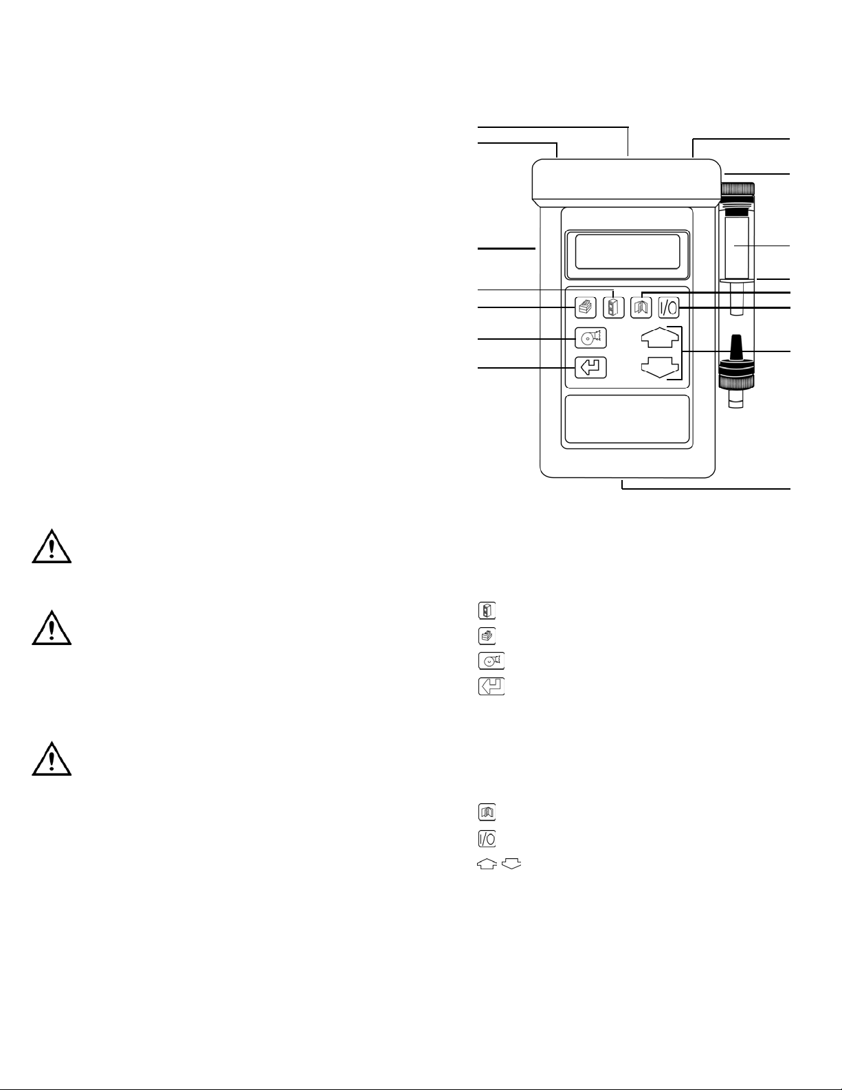
C o n t r ols and Indicators
1. I n f r a - R ed Emitter
2. RS232 (8 pin din)
3. Charger Socke t
4. S t o r e : Enters data storage menu.
5. P r i n t : Prints current data.
6. P u m p : Turns pump on and off.
7. E n t e r : Accepts a command which enters a menu option.
8. P r e s s u r e Inlet
9. Inlet Po r t
10. Particle Filter
11. In-Line Water Tra p
12. M e n u : A l l ows access to all menu functions.
13. O n / O f f : Powers instrument on and off.
14. U p / D o w n : Scrolls up or down through option menus.
15. Flue Te m p e r a t u r e Connector
Introduction
The KM900CO/P is designed for commercial and light industrial
c o n t r actors and technicians. Includes seven preprogrammed fuels with
two positions for user-specified fuels. With 150 memory locations, tests ca n
be stored and downloaded to the optional IR printer through the infra r e d
port or to a PC through the RS 2 32 port utilizing the optional Firew o r k s ™
s o f tware package. The unit comes complete with a large ca r ryi ng case,
12” 1200˚F probe and battery charger.
Features include
• Measures O2 and CO
• Calculates CO2, efficiency and excess air
• 0 to 10,000 ppm H2 compensated CO sensor
• Large 4 line display
• Long life rechargeable battery
• Large cordura case
• 150 memory positions
• Upgrades available include NOx, SO2and Draft
Safety Notes
Before using this instrument, read all safety information carefully. In
this manual the word "WARNING" is used to indicate conditions
or actions that may pose physical hazards to the user. The word
"CAUTION" is used to indicate conditions or actions that may
damage this instrument.
WARNING!
Exceeding the specified limits of this instrument is dangerous and can
expose the user to serious or possibly fatal injury.
WARNING!
This analyzer extracts combustion gases that may be toxic in relatively
low concentrations. These gases are exhausted from the side of the
instrument. This instrument must only be used in well ventilated
locations. It must only be used by trained and competent persons after
due consideration of all the potential hazards.
WARNING!
This instrument is designed as Class III equipment and should only be
connected to SELV circuits. Protection against elctrical shock in accordance with EN 61010-1 : 1993.
The battery charger is designated as:
Class II equipment
Installation category II
Pollution degree 2
Indoor use only
Altitude to 2000m
Ambient temperature 0˚ to 40˚C
Maximum relative humidity 80% for temperatures up to 31˚C linearly
to 50% RH at 40˚C
Mains supply functions no to exceed 10% of the nominal voltage.
KM900CO/P-MAN P. 1
1
2
3
4
5
6
7
8
9
10
11
12
13
14
15
Page 3
The calibration time will count down in seconds to zero. Calibration
time may be changed from 2 to 6 minutes. See SET-UP MENU section.
NOTE: Three minutes is recommended to allow the sensors to stabilize
fully. Anything less than this may result in drift of the toxic and oxygen
sensors in clean ambient air.
To obtain the quoted specification the instrument should be calibrated
with clean ambient air at standard temperature and pressure (STP).
Once the time has reached zero, an audible beep will be heard and will
show the selected fuel on the following display:
Press “ “. This zeros the toxic sensor and sets Oxygen to 20.9%. The
next screen is the MAIN DISPLAY of the analyzer.
Use “ “ and “ “ to change the display.
All parameters are detailed in the glossary.
Main Displays
The main display can be changed to show either 4 or 8 parameters at
one time. Two options are available when 4 parameters are selected.
• 4 Page Mode: Displays 4 lines of data in set format, each
page is predefined.
• Line Scroll Mode: Allows you to customize the display to
show the data you require.
• 8 Page Mode: Displays 8 parameters on 4 line in set format,
the bottom two can be changed.
Changing between the different modes is detailed under Display
Menu Section
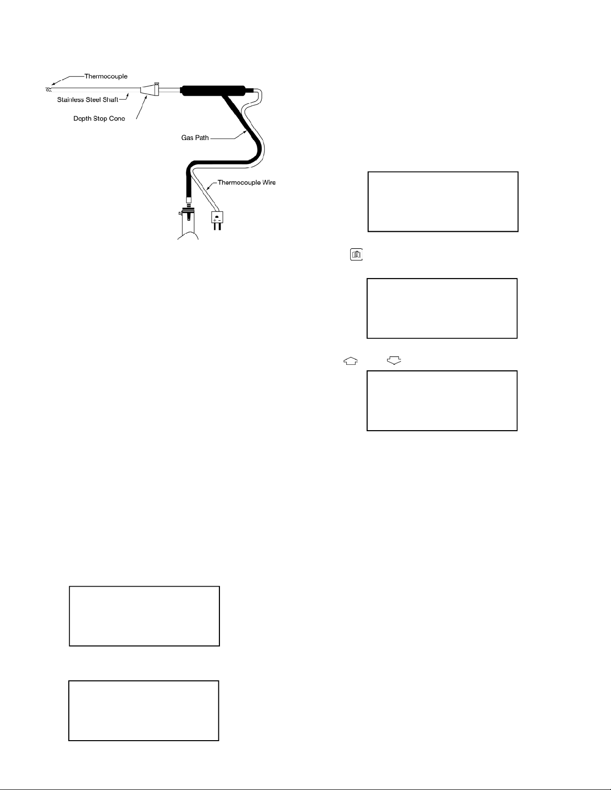
Thermocouple Probe Description
1. Stainless Steel Shaft
2. Depth Stop Cone
3. Gas Pa t h
4. T h e r m o c ouple Wire
Operating Instructions
If you are using this instrument for the very first time be sure to charge
the battery for a period of 12 hours.
Before every use, check for the following:
• The particle filter is not dirty
• The water trap and probe line are empty of water
• All hose connections are properly connected
• The probe is sampling clean ambient air
• The water trap is correctly fitted and the instrument is upright
• The flue temperature is connected
Automatic Calibration
Turn on instrument. During this sequence the analyzer pumps fresh air
into the sensors to allow toxic sensors (if fitted) to be set to zero and
the Oxygen sensor to be set to 20.9%.
After switching on the analyzer, it will briefly display header information:
It will then show the count-down screen:
KM900CO/P-MAN P. 2
NATURAL GAS
*PRESS -MENU- KEY*
NETT C . . . 0.0
O2 % . . . 20.9
CO PPM . . . 0000
EFF (G) % . . . 0.0
CO2 %. . . . . . . 0.0
FLUE C. . . . . . . 0.0
INLT . . . NOT FITTED
AMBIENT C . . . . 21
Kane International
(44)-1707-37550
ZERO CAL
Time : 180
FRESH AIR PURGE
Page 4

Page Mode
Use the “ “ and “ “ keys to change the information that is
displayed on the screen. The following pages are available.
NOTE: This screen only displayed on an analyzer fitted with an NO sensor.
NOTE: In 4 page mode only “ “ turns the backlight ON or OFF.
Line Scroll Mode
Line scroll mode allows you to customize the display.
Use the “ “ and “ “ keys to change the bottom of the display.
Once the correct line is displayed press “ “ to confirm and move
the line up. Select the next parameter and repeat until all lines display
the desired parameters.
Change bottom line using
“ “ and “ “ keys.
“ “ to select and move
parameter up
Select next parameter.
Repeat above until display
reads desired data.
8 Page Mode
Displays 8 parameters on the screen at one time. Symbols used in this
mode are different to those used in 4 Page Mode and line scroll modes
and are detailed in “MAIN DISPLAY PARAMETERS”.
Main Display Parameters
The bottom line of the display can be changed to display other para m e t e r s .
Use the “ “ and “ “ keys to change this line.
Sampling The Flue Gas
Once the automatic calibration procedure has been completed and the
specific fuel has been selected the probe can be inserted into the
desired sampling point.
It is recommended that the sampling point be located at least two
diameters downstream of any bend and that the probe tip is in the
center of the flue. With balanced flue and other domestic units the
probe should be positioned far enough into the flue so that no air can
“back flush” into the probe. This will be indicated by a low oxygen
reading and/or a low “Poison Index” reading. (Fig 1).
The probe depth stop cone provided with the instrument allows the
probe to be used in holes whose diameters range from 8 mm to 21 mm
(5/16 to 13/16 inch).
The standard probe is rated at 1200˚F. Temperature of up to 2012˚F
(1100˚C) can be accommodated using an optional high temperature
probe.
NOTE: To conserve battery power, switch off the pump when you are
not taking a measurement. Use the “ “ key to turn “ON” and
“OFF” the pump.
KM900CO/P-MAN P. 3
NATURAL GAS
DATE . . . 07-08-96
TIME . . . 12:31:35
BATTERY % . . 54
NETT F . . . 0.0
O2 % . . . 20.9
CO ppm . . . 0000
EFF (G) % . . . 0.0
CO2 % . . . 0.0
FLUE F . . . 0.0
INLT NOT FITTED
AMBIENT F . . . 72
CO/CO2 R . . . 0.0001
P INDEX % . . . 0.01
XAIR % . . . 0.0
Prs mbar 0.00
NO ppm . . . 0000
NOx ppm . . . 0000
NOx calc % . . . 5
O2 ref % . . . 3.0
NETT F . . . 0.0
O2 % . . . 20.9
CO ppm . . . 0000
CO2 % . . . 0.0
O2 % . . . 20.9
CO ppm . . . 0000
CO2 % . . . 0.0
CO2 % . . . 0.0
O2 % . . . 20.9
CO ppm . . . 0000
CO2 % . . . 0.0
CO/CO2 R . . . 0.0001
O2 :20.9% CO2 : -CO : 0ppm Eff : -PI : -- ∆T : 0F
: -- Tf : 73F
(Fig 1)
Page 5

Taking A Pressure Reading
With the optional pressure module fitted a flue draft measurement can
be made at any time.
Connect the standard probe to the pressure sensor inlet and the probe
in the flue. The pressure reading will be displayed:
To perform a combustion test and display draft pressure at the
same time a special probe is required. Please contact UEi for service
information.
Regular Checks During Sampling
Care must be taken at all times not to exceed the analyzers operating
specifications, in particular ensure the following:
• Do not exceed the maximum temperature of the flue probe.
• The analyzer internal temperature does not exceed normal
operating range, typically 32˚ to 104˚F (0˚ to 40˚C).
• Do not place the instrument on a hot surface.
• The water trap is vertical at all times. Water condenses in the
probe line and can quickly fill the water trap when the probe is
moved. Take care and watch the water trap closely.
• The in-line particle filter is clean and does not become blocked.
Normal Shutdown Sequence
CAUTION!
Do this every time you use the analyzer.
Remove the probe from the flue (CAUTION! The probe will be HOT)
and allow it to cool naturally. Do not immerse the probe in water as this
will be drawn into the analyzer and damage the pump and sensors.
Once the probe is removed from the flue and readings have returned to
zero, press “ “ and the analyzer will count down from 30 to switch off.
If you have not finished but pressed “ “ by mistake, you can press
“ “ to return to normal operation and not switch OFF.
Electromagnetic Compatibility
The European Council Directive 89/336/EEC requires that electronic
equipment does not generate electromagnetic disturbances that exceed
defined levels and has an adequate level of immunity to enable it to be
operated as intended. The specific standards applicable to this product
are detailed in the MAIN DISPLAY PARAMETERS.
Since there are many electrical products in use that pre-date this
Directive and may emit electromagnetic radiation in excess of the
standards defined in the Directive there may be occasions where it
would be appropriate to check the analyzer prior to use.
The following procedure should be adopted:
1. Go through the normal start up sequence in the location where
the equipment is to be used.
2. Switch on all localized electrical equipment that might be capable
of causing interference.
3. Check that all readings are as expected. (A level of disturbance in the
readings is acceptable). If not, adjust the position of the instrument
to minimize interference or switch off, if possible, the offending
equipment for the duration of the test.
4. N.B. Maximum cable lengths must be less than 3 meters.
NOTE: At the time of writing this manual (January 1997) Kane
International Ltd is not aware of any field based situation where such
interference has ever occured and this advice is only given to satisfy the
requirements of the Directive.
Moving Through The Menus
Basic Operation:
From the “MAIN DISPLAY”
Press “ “ to access
the “MAIN MENU”
Press “ “ and “ “
to move cursor up and down
Press “ “ to access
selected menu
Press “ “ to access
select parameter
Press “ “ and “ “
to change setting
i.e. fuel selected
KM900CO/P-MAN P. 4
CO/CO2 R . . . 0.0001
P INDEX % . . . 0.01
XAIR % . . . 0.0
Prs inWG 0.00
OFF 30
MENU TO ESCAPE
NETT F . . . 0.0
O2 % . . . 20.9
CO ppm . . . 0000
EFF (G) % . . . 0.0
MAIN MENU
1. SELECT 3. DISPLAY
2. UNITS 4. SETUP
MAIN MENU
1. SELECT 3. DISPLAY
2. UNITS 4. SETUP
FUEL : LIGHT OIL
O2 Ref : OFF
SMOKE : OFF
RESET : NO
MAIN MENU
1. SELECT 3. DISPLAY
2. UNITS 4. SETUP
FUEL : NATURAL GAS
O2 Ref : OFF
SMOKE : OFF
RESET : NO
Page 6

KM900CO/P-MAN P. 5
Press “ “ to enter value
and move to next parameter
Press “ “ to save
settings and return to the
“MAIN MENU”
Press “ “ to save settings and return to the “MAIN DISPLAY”
Main Menu
The MAIN MENU consists of 4 sub menus which are shown below and
detailed in the following sections.
All sub-menus are accessed using “ “ and exited using “ “.
The “ “ and “ “ keys move the cursor within a menu and allow
parameters to be changed.
NOTE: Holding down one of these keys scrolls thro u gh the data quicke r.
Select Menu
This menu allows selections
to be made for the
parameters detailed below.
FUEL: Select the fuel being used by the boiler from either a
standard fuel stored in the analyzer or by entering the user
fuel. Once the correct fuel has been selected press “ “
to view the fuel constants.
Calculations of fuel constants are detailed in the glossary. Fuel constants
will have to be calculated before a user fuel can be entered.
To enter the user fuel select
“User Fuel” and Press
“ “.
Use “ “ and “ “
to select the correct value.
Use “ “ to move to the next parameter, repeat above until all
parameters are correct. Press “ “ to return to “SELECT” menu.
O2 Ref: Toxic gas measurement can be referenced to defined
oxygen levels. Reference values can be set from 1 - 20%, to
AUTO or more normally to the default value - OFF. Setting
to AUTO uses the figure in the “FUEL” constants data.
Oxygen referencing is required by some regulations such as
TA-LUFT. If a reference value is selected then toxic gas
measurements will be displayed with the symbol “(n)”
attached to the reading. Example: CO(n).
What does Oxygen reference mean?
If 3% O2reference is selected and 5% O2is measured in
the flue then toxic gas values will be recalculated as if 3%
were measured. The equation for referencing is detailed in
the glossary.
Oxygen referencing prevents false readings being
submitted, e.g. allowing more air into the boiler will
increase the oxygen level in the flue and hence dilute any
toxic gas reading. Oxygen referencing gives readings as if
they were undiluted.
SMOKE: Allows the user to enter a smoke test number from 0 - 9.
This value will be printed on the standard printout. Default
value is OFF.
RESET: Allows the user set the Oxygen to 20.9% and zero the toxic
sensors without turning the analyzer off.
Selecting “YES” and “ “ will display the following screen:
After pressing “ “ the analyzer will count down for 5 seconds and
then return to the main display.
FUEL : LIGHT OIL
O2 Ref : OFF
SMOKE : OFF
RESET : NO
MAIN MENU
1. SELECT 3. DISPLAY
2. UNITS 4. SETUP
MAIN MENU
1. SELECT 3. DISPLAY
2. UNITS 4. SETUP
FUEL : LIGHT OIL
O2 Ref : OFF
SMOKE : OFF
RESET : NO
NATURAL GAS
K1g : 0.350 K1n : 0.390
K_2 : 11.89 K_3 : 9.83
K_4 : 32 O2r : 3.0
USER FUEL
K1g : 0.000 K1n : 0.000
K_2 : 0.00 K_3 : 0.00
K_4 : 00 O2r : 00
USER FUEL
K1g : 0.350 K1n : 0.000
K_2 : 0.00 K_3 : 0.00
K_4 : 00 O2r : 00
RESET SENSORS
O2 % : 20.9 CO & NO = 0
PRESS ENTER
MENU TO ESCAPE
Page 7

WARNING!
The sensors must only be reset if you are sure they have been sampling
fresh air for at least 3 minutes. Errors in measurement will occur if the
sensors are reset during or just after sampling.
Units Menu
Allows all displayed units
to be changed.
TEMP: Choose selections from Centigrade ˚C or Fahrenheit ˚F.
GAS: Changes the toxic gas measurement units. Select from
volumetric readings, parts per million (ppm) or mass flow
reading milligrams per cubic meter (mg/m3).
PRESS: Flue draft can be displayed in millibar (mbar),
hectaPascals (hPa), millimeters water gauge (mmWG) or
inches water gauge (in WG).
EFF: Efficiency can be selected for Gross or Net values. Gross
efficiency assumes latent heat of vaporization is lost in the
boiler and hence will be lower than Net efficiency. For
Natural Gas the difference will be approximately 11%.
Display Menu
Allows the configuration
of the display to
be changed.
LIGHT: Choose from “ON” or “OFF”.
MODE: Select 4 or 8 Page Mode or Line Scroll Mode as detailed in
Main Displays.
CONTRAST: The contrast is set to a DEFAULT value or can be adjusted
lighter or darker. use the “ “ and “ “ keys
to adjust.
Set-Up Menu
The set up menu allows the following parameters to be set/altered.
• L a n g u a g e
• Automatic ca l i b ration time
• CO gas alarm
• NOx percentage for ca l c u l a t i o n
• Date and time
• Printout header
TEMP : C
GAS : ppm
PRESS : MBAR
EFF : GROSS
LIGHT : OFF
MODE : 8-PAGE
CONTRAST : DEFAULT
LANG : ENGLISH ZERO : 3
CO ALARM : 400 NOx% : 5
CALENDAR HEADER
KM900CO/P-MAN P. 6
Parameter Description Settings
LANG: Changes the analyzer displayed ENGLISH
and printed language SPANISH
DUTCH
FRENCH
ITALIAN
ZERO: Allows setting of the Autocalibration 2-6 minutes
time in minutes. Care must be taken
when changing this parameter as
sensors may drift from zero if too
short a time is used. 3 minute
countdown is advised.
CO ALARM: Allows an alarm level to be set on OFF
for the CO reading. This is set as a 0-4000 ppm
default at 1000 ppm.
Once an alarm has been exceeded the display will
flash every two minutes warning the user of an
alarm state and display the gas concentration. A
similar display will be shown during a
“RECH A RGE BATTERY” and “PUMP OFF” alarms.
NO REF: Displayed on the Nitric Oxide unit OFF
only. Allows the percentage P in the 1-9%
following calculation to be set. The
default value set is 5%.
NOTE: The percentage allows for
NO2in a typical boiler.
NO2= NO + P% NO
CALENDAR: Allows the user to change the date and time.
(24 hour clock). The following screen will be
shown once the parameter is entered:
FORMAT: Changes the date format for display and printing.
To change the time position the cursor on “TIME”
and press “ “. The cursor will now be to the
left of the 13 as shown below:
Using “ “ and “ “ scroll through the setting
options i.e. 0-23.
hh : mm : ss
TIME: 13 : 53 : 26
FORMAT: dd : mm : yy
DATE: 03 : 01 : 96
hh : mm : ss
TIME: 13 : 53 : 26
FORMAT: dd : mm : yy
DATE: 03 : 01 : 96
-- -- -- -- -- -- -- -- -- -- -- -- -- -- -- -- -- -CO ALARM
1010 ppm
-- -- -- -- -- -- -- -- -- -- -- -- -- -- -- -- -- --
Page 8

Printing a “LIVE” Test
During a combustion test the KM900CO/P will print data on request.
With the analyzer showing the “MAIN DISPLAY” press “ “ and
current data will be sent to the printer.
The display will show the following until data transmition is complete.
Standard Printout
The standard printout is shown below:
Storing and Retrieving Data
The KM900CO/P can store up to 150 combustion tests. Once stored, the
data can be viewed on the display or downloaded to a PC or printer.
Storing a “Live” Test
While performing a test and viewing the data on the MAIN display
access the “STORE” menu as follows:
Press “ “ to access
the “STORE MENU”.
The cursor will move to the first number, use the “ “ and “ “ to
select the location and start printing.
Once the correct hour is set press “ “ to move to the
next parameter, the cursor will move to the left of minutes
(53). Move to each parameter until the correct time is set.
Pressing “ “ after setting the seconds will return the
cursor to the left of the screen.
Format and Date are set in a similar manner.
HEADER: Allows two lines of 20 characters to be programmed into
the analyzer. The header appears on the top of the standard
printout. This can be used to print your company name
and/or phone number.
The screen above shows the standard header setting with
the cursor now shown underlining the K in Kane. By using
“ “ and “ “ any letter or number can be chosen.
Once the correct character is displayed, use “ “ to
move right to the next. Move along until all characters spell
the desired name or phone number. If you need to go back
and change a character use “ “ to move left.
Press “ “ to return to the “SET UP” menu.
Printing Information
Supplied as accessories for the KM900CO/P is an infra-red thermal
printer. Read the manual supplied with the printer prior to operation.
Connection to the KM900CO/P are detailed below:
• Infra-red Thermal Printer - this does not require a cable to
transmit the data but uses an infra-red (IR) link similar to a TV
remote control. The IR emitter is positioned on the top of the
KM900CO/P and the bottom of the printer. Ensure they are
pointing at each other and within 1 foot, with no obstructions
in the way. Data may be lost if transmission is interrupted. Keep
the KM900CO/P pointing at the printer until the printout
has finished.
Data can either be printed from a live test or from stored data. Printing
of stored data is detailed in “Storing and Retrieving Data”.
KM900CO/P-MAN P. 7
Name/Phone
Kane International
(44)-1707-375550
‘LEFT’ USE STORE KEY
***** Printing *****
KM900
Kane International
(44)-1707-375550
TEST 36
DATE: 01-01-96
TIME: 15:46:52
NATURAL GAS
NET F . . . . . . . . . . . . . . . . . . . . . .2
O2 % . . . . . . . . . . . . . . . . . . . .20.3
CO ppmn O2 > . . . . . . . . . . . .20%
EFF % (G) . . . . . . . . . . . . . . . .87.8
CO2 % . ˚ . . . . . . . . . . . . . . . . . .0.3
FLUE F . ˚ . . . . . . . . . . . . . . . . . .78
INTL F . ˚ . . . . . . . . . . .NOT FITTED
AMBIENT C . . . . . . . . . . . . . . .76.2
CO/CI2 R . . . . . . . . . . . . . . .0.0000
P INDEX % . . . . . . . . . . . . . . .0.00
XAIR % . . . . . . . . . . . . . .02 > 20%
Prs inWG . . . . . . . . . . . . . . . . . .0.0
STORE MENU
MODE : PRINT
LOCATION : 1 TO 10
PRESS “PRINT”
Page 9

Main Display Parameters
The parameters and their meanings are detailed as follows:
DATE: Analyzer date. (see “SET-UP MENU” to change)
TIME: Analyzer time. (see “SET-UP MENU” to change)
BATTERY: Displays the battery level from 0-100%. The analyzer will
(BAT) flash “RECHARGE BATTERY” at less than 10% of charge.
With the charger connected the display shows “AC ON”.
NETT: Nett temperature calculated by deducting the internal
(∆T) AMBIENT temperature from the measured FLUE
temperature. Displays in either ˚F or ˚C and will display
“NOT FITTED” (N/F) if flue probe is not connected.
If an external INLET probe is used then INLET is deducted
from FLUE.
O2: Oxygen reading in percentage %.
CO: Carbon Monoxide reading indicated in ppm or mg/m3. If the
figures are referenced to oxygen then the display will show
“CO (n)”. See “SELECT M ENU” for oxygen reference. The
display will read “O2>20%” if referenced values selected
and instrument is in clean ambient air.
EFF (G): Combustion Efficiency calculation displayed in percentage.
Gross G or Net N can be set, see “SELECT MENU”. The
calculation is determined by fuel type for calculation. The
efficiency is displayed during a combustion test, “--” is dis
played while in fresh air.
CO2: Carbon Dioxide calculation determined by the type of fuel.
This only shows a reading when a combustion test is being
carried out. “--” is displayed while in fresh air.
FLUE: Temperature measured by flue gas probe in Centigrade or
(Tf) Fahrenheit. Will show temperature after fresh air and “NOT
ca l i b r a t i o n FITTED (N/F)” or “FAULT (FLT)” if probe disconnected.
INLET: Temperature measured by the optional inlet air probe. This
(Ti) probe is plugged into the instrument through the RS232
socket. This figure is used to calculate the NET temperature
instead of AMBIENT when fitted.
AMBIENT: Temperature measured by the internal sensor, used in the
(Ta) NET temperature calculation if an INLET probe is not fitted.
CO/CO2 R: The CO/CO2 ratio, is the ratio of measured CO divided by
calculated CO2.
It gives an indication of the following:
• How good a gas sample the instrument is reading
• How clean the boiler is running
For example: A new or clean domestic boiler will display a
ratio of less than 0.004, a unit in need of cleaning 0.004-
0.008 and a unit in need of major overhaul will show
greater than 0.008.
This only shows a reading when a combustion test is being
carried out. “--” is displayed while in clean ambient air.
P INDEX: The CO/CO2 ratio expressed as a percentage %, called the
(Pi) “Poison Index” i.e. P INDEX % = 100 x CO/CO2. “--” is
displayed while in clean ambient air.
Press “ “ to move the cursor to the second number, select the last
location to print.
To print the data press “ “. In the screen shown above, locations 1
to 10 will be printed.
During printing the following will be shown:
NOTE: While the display above is shown (i.e. the instrument in printing
a test) the keypad is disabled . To exit from printing wait until the
current test has finished and the display below is shown.
Press “ “ to exit the print
routine. The instrument will
return to main display.
Deleting Data
To delete the data in stored memory press “ “ to obtain the “STORE
MENU” (as above).
Press “ “ to access
the “STORE MENU”.
Press “ “ to access
delete data screen.
Press “ “ to delete data in memory, press “ “ to exit delete
data screen.
KM900CO/P-MAN P. 8
PRINT TESTS
1 to 10
PRINTING TEST 1
PRINT TESTS
1 to 10
PLEASE WAIT
MENU TO ESCAPE
STORE MENU
MODE : DELETE
LOCATION : 3
PRESS “ENTER” TO DELETE
ENTER to ERASE DATA
MENU to ESCAPE
Page 10

Efficiency Calculation
Known Data - Fuel Qgr = Gross Calorific Value (kJ/kg)
Qnet = Net Calorific Value (kJ/kg)
K1 = Constant based on Gross or Net Calorific Va l u e
K1g = (255 x %Carbon in fuel)/Qgr
K1n = (255 x %Carbon in fuel)/Qnet
K2 = % max theoretical CO2(dry basis)
K3 = % Wet Loss
H2= % Hydrogen
H2O = % Water
Measured Data: Tf = Flue Temperature
Ti = Inlet Temperature
O2m = % Oxygen in flue gas
O2r = Oxygen reference %
Calculated Data: Tnet = Net Temperature
% CO2 content in flue gas
% Dry Flue Gas losses
% Wet losses
% Unburned carbon loss
% Efficiency
Tnet = Flue Temperature - Inlet Temperature
Dry flue gas loss % = 20.9 x K1 x (Tnet)/K2 x (20.9 - O2m)
Wet loss % = 9 x H2+ H2O/Qgr x [2488 + 2.1Tf - 4.2 Ti]
Simplified = [(9 x H2+ H2O)/Qgr] x 24 25 x [1 + 0.001 Tnet]
Wet loss % = K3(1 + 0.001 x Te n t )
Where K3 = [(9 x H2+ H2O)/Qgr] x 24 25
Net Efficiency % = 100 - dry flue gas losses
= 100 - 20.9 x K1n x (Tnet)/K2 x (20.9 - O2m )
Gross Efficiency % = 100 - {dry flue gas losses + wet losses}
= 100 -{[20 . 9 % / ( 2 0.9 x K1g x (Tnet)/K2 x
( 2 0.9 - O2m)]+[K3 x (1 + 0.001 x Tnet)]}
Excess Air = [(20 . 9 % / ( 2 0.9% - O2m%)) - 1] x 10 0 %
CO2% = [(20.9 - O2m) x K2/20 . 9 ]
Unburned fuel loss% = K4 x CO / ( C O + CO2)
NOTE: CO scaled in %
Where K4 = 70 for coke
= 65 for anthra c i t e
= 63 for Bituminous coal
= 62 for coal tar fuel
= 48 for liquid petroleum fuel
= 32 for natural gas
The formula for K4 is based on the gross calorific value Qgr. To obtain the
loss based on net calorific value multiply by Qgr/Qnet. Since this loss is
usually small this conversion has been ignored. This loss is subtra c t e d
from the efficiency.
Oxygen Reference CO(n) = CO x (20.9 - O2r )
( 2 0.9 - O2m )
XAIR %: Excess air calculated from the measured oxygen and type of
( ) fuel used. During a combustion test “O2>20%” will be dis
played while in clean ambient air.
Prs: Flue draft pressure reading. Displayed when pressure
sensor fitted. See “UNITS MENU” for scales.
NO: Nitric Oxide reading in ppm or mg/m3. Displayed when
Nitric Oxide sensor fitted. Also displayed as “NO (n)” when
referenced to oxygen. The display will read “O2>20%” if
referenced values selected and instrument is in clean
ambient air.
NOx: Calculated total Nitric Oxides displayed in ppm or mg/m3.
Where NOx = NO + P%NO, note P can be set from 0-9%,
default = 5%. See “SELECT MENU”. Also displayed as
“NOx (n)” referenced to oxygen. The display will read
“O2>20%” if referenced values are selected and instrument
is sampling clean ambient air.
SO2: Sulphur Dioxide reading in ppm or mg/m3. Displayed when
Sulphur Dioxide sensor fitted. Also displayed as “SO2 (n)”
referenced to oxygen. The display will read “O2>20%” if
referenced values selected and instrument is in clean
ambient air.
O2 ref%: Toxic gas measurements can be referenced to defined
(O2r) oxygen levels. See “SELECT MENU” for details.
Combustion Efficiency Calculation
The efficiency calculation is based upon British Standard BS845.
This identifies three sources of loss associated with fuel burning:
Losses due to flue gasses: Dry Flue gas loss
Moisture and hydrogen
Sensible heat of water vapor
Unburned gas
Losses due to refuse: Combustible in ash
Combustible in riddling
Combustible in dust
Other losses: Radiation
Convection
Conduction
Other unmeasured losses
Net efficiency calculations assume that the energy contained in the
water vapor (formed as a product of combustion and from wet fuel) is
recovered and the wet loss term is zero. Gross efficiency calculations
assume that the energy contained in the water vapor is not recovered.
Since the fuel to combustible matter in ashes, riddling, dust and grit,
radiation, convection and conduction are not included.
KM900CO/P-MAN P. 9
Page 11

M a i n t e n a n c e
Periodic service
WARNING!
Repair and service of this instrument is to be performed by qualified
personnel only. Improper repair or service could result in physical
degradation of this instrument. This could alter the protection from
electrical shock and personal injury this instrument provides to the
operator. Perform only those maintenance tasks that you are
qualified to do.
These guidelines will help you attain long and reliable service from
your i n s t r u m e n t:
1. Calibrate your i n s t r u m e n t annually to ensure it meets original
performance specifications.
2. Keep your instrument dry. If it gets wet, wipe it dry immediately.
Liquids damage electronic circuits.
3. Whenever pra c t i cal, keep the instrument away from dust and dirt,
which can cause premature wear.
4. Although your instrument is built to withstand the rigors of daily use,
it can be damaged by severe impacts. Use reasonable caution when
using and storing the instrument.
Cleaning and Decontamination
Periodically clean your meter’s case using a damp cloth. DO NOT use
abrasives, cleaning solvents or strong detergents, as they may damage
the finish or affect the reliability of the structural components.
Emptying and Cleaning The In-line Water Trap
The in-line water trap should be checked and emptied on a regular
basis. Water vapor will condense and gather in the probe line. This may
move suddenly to the trap when the probe is moved. Care should be
taken at all times.
Emptying of the water trap is detailed below:
Carefully remove the end cap from the in-line housing. Dispose of the
condensate in a suitable drain, care must be taken as it could be acidic.
If condensate spills onto the skin or clothing, clean off immediately
using fresh water, seek medical advice if problems occur.
Calculation of Fuel Data
For any fuel not specified by UEi the net calorific value, gross calorific
value and composition should be obtained from the fuel supplier.
The following fuel data has been calculated with reference to the
efficiency calculation.
Example:
Chemical composition: C 25%
H
2
3%
H2O 50%
Qnet 8.35 MJ/kg
Qg 9.3 MJ/kg
Max CO
2
20.4%
K 1 n = (255 x % carbon in fuel)/Qnet (kJ/Kg)
= (255 x 25 ) / 8 350 = 0.76 3
K 1 g = (255 x % carbon in fuel)/Qg (kJ/Kg)
= (255 x 25 ) / 9 300 = 0.685
K 2 = Max % CO2= 20 . 4 0
K 3 = Wet Lo s s = [(9 x %H2+ %H2O ) / 9 3 00] x 24 25
= [(9 x 3 + 50)/9300] x 2425
= (77/9300) x 2425 = 20.08
K4 = 65 (an approximation for wood)*
The fuel values to program into the analyzer are as follows:
*Assumed values in the absence of supplied data.
Electromagnetic Compatibility (CE) Statement
This product has been tested for
compliance with the following generic
standards:
EN 50081-1
EN 50082-1
and is certified to be complaint
Specifications EC/EMC/KI/KM900
details the specific test configuration,
performance and conditions of use.
KM900CO/P-MAN P. 10
NATURAL GAS
K1g : 0.763 K1n : 0.685
K_2 : 20.4 K_3 : 20.08
K_4 : 65 O2r : 8.0
Page 12

S p e c i f i c a t i o n s
*1Using dry gases at STP
*2Calculated
Changing The Particle Filter
This is a very important part of the analyzer and should be changed
regularly. If prevents dust and dirty particles entering the pump and
sensors and hence causing damage. The filter MUST be changed when
it is discolored.
Remove the end cap from the in-line filter housing. Carefully remove
the paper filter element and dispose of it. Clean the inside of the filter
housing with a suitable soft cloth. Insert a new filter element onto the
spigot in the filter housing and carefully replace the end cap.
Annual Re-calibration
While the sensors have an expected life of more than two years in
normal use it is recommended that the analyzer is re-calibrated at least
annually. This is so that long term drift on the sensors and electronics
can be eliminated. Local regulations may require more frequent
re-calibration and users should check with appropriate authorities to
ensure they comply with relevant guidelines.
Tro u b l e s h o o t i n g
The following is a list of problems that may occur on the instrument
through it operating life. If the cause of the fault is not easy to identify
then we advise you contact UEi service department for expert advice.
KM900CO/P-MAN P. 11
Parameter Resolution Accuracy Range
Temp Measurement
Flue Temperature 1.0˚C/F ±2.0˚C±0.3% reading 32-1112˚F
(0-600˚C)
Inlet Temperature 0.1˚C/F ±1˚C±0.3% reading 32-122˚F
(0-50˚C)
Gas Measurement
Oxygen 0.1% ±0.2%*
1
0-21%
Carbon Monoxide 1 ppm, ±20 ppm<400 ppm*10-4000 ppm
mg/m
3
±5%>400 ppm 0-5000 mg/m
3
Carbon Monoxide, H2 1 ppm ±20 ppm<400 ppm*10-10,000 ppm
compensated mg/m
3
±5%>5000 ppm 0-12,000 mg/m
3
±10%>5000 ppm
Nitric Oxide 1 ppm ±5 ppm<100 ppm*10-5000 ppm
(optional) mg/m
3
±5%>100 ppm 0-6700 mg/m
3
Pressure (optional) 0.1 mbar ±5.0% full scale 150 mbar
Carbon Dioxide*2 0.1% ±0.3% reading 0-99.9%
Losses*
2
0.1% ±1.0% reading 0-99.9%
Efficiency*
2
0.1% ±1.0% reading 0-99.9%
Excess Air*
2
0.1% ±0.2% 0-2885.0%
Temp (Nett)*
2
1.0˚C/F ±2˚C±0.3% reading 32-1112˚F
(0-600˚C)
CO/CO2ratio*
2
0.0001 ±0.0001 0-0.9999
Poison Index*
2
0.01% ±0.01 0-99.99
Pre-programmed Fuels Natural gas, Town gas, Gascor, Light Oil, Heavy Oil,
Propane, Butane, Anthracite, Coke, Coal, Kinsale Gas.
Dimensions
Weight 2.2 lbs. (1kg)
Handset 220 mm x 55 mm x 120 mm
Probe (L) 240 mm x (Dia) 8 mm with 285 mm long stainless
steel shaft, type-K thermocouple and 1.5 m long
neoprene hose
Ambient operating 32˚ to 104˚F (0˚ to 40˚C) 10% to 90% RH non condensing
range
Power supply Input: 110V AC/220V AC nominal
(battery charger) Output: 12V AC off load
Battery life >8 hours from full charge
Dimensions 8.7” x 2.2” x 4.7” (220mm x 55mm x 120mm)
Symptom Cause
Oxygen too high or Air leaking into probe, tubing, water trap, connectors
CO2too low or internal to instrument
Oxygen cell needs replacing
Oxygen Error (FAULT) or Calibration time set too short and instrument not
Toxic sensor Error (FAULT) allowed to stabilize
Instrument has been stored in a cold environment and
is not at normal working temperature
Oxygen cell or toxic sensors needs replacing
Analyzer not holding Battery exhausted
charge or Analyzer not AC charger not giving correct output
charging Fuse blown in charger plug
Analyzer does not respond Particle filter blocked
to flue gas Probe or tubing blocked
Pump not working or damaged with contaminents
Probe connected to pressure connector
Flue temperature reading Temperature plug reversed in socket
erratic Faulty connection or break in cable or plug
Analyzer automatically Battery below alarm level
switches off in operation Ambient temperature above 50˚C
Battery quickly discharging and is faulty
Display shows dark lines Fault has occurred on the instrument electronics and
and no response from requires resetting
ON/OFF key
Page 13

Limited Warranty
The KM900CO/P is warranted to be free from defects in materials and workmanship for a
period of one year (two year on sensors) from the date of purchase. If within the warra n ty
period your instrument should become inoperative from such defects, the unit will be
repaired or replaced at UEi’s option. This warra n ty covers normal use and does not cover
damage which occurs in shipment or failure which results from alteration, tampering,
accident, misuse, abuse, neglect or improper maintenance. Batteries and consequential damage resulting from failed batteries are not covered by warra n ty.
Any implied warranties, including but not limited to implied warranties of merchantability
and fitness for a particular purpose, are limited to the express warranty. UEi shall not be
liable for loss of use of the instrument or other incidental or consequential damages,
expenses, or economic loss, or for any claim or claims for such damage, expenses or
economic loss. A purchase receipt or other proof of original purchase date will be required
before warra n ty repairs will be rendered. Instruments out of warra n ty will be repaired (when
r e p a i r able) for a service charge. Return the unit postage paid and insured to:
1-800-547-5740 • FAX: (503) 643-6322
www.ueitest.com • Email: info@ueitest.com
This warranty gives you specific legal rights. You may also have other rights which vary from
state to state.
KM900CO/P
Combustion Efficiency Analyzer
Copyright © 2007 UEi KM900CO/P-MAN 1/07
PLEASE
RECYCLE
 Loading...