

1-800-547-5740 • Fax: (503) 643-6322
www.ueitest.com • email: info@ueitest.com
ATLFSG
INSTRUCTION MANUAL
Introduction
The ATLFSG test lead adapter kit lets you use your standard multimeter
(with micro-amps measurement function) to test common
flame-safeguard circuits that use standard 3.5 mm stereo jack.
Safety Notes
Observe all safety precautions when measuring higher voltages. Turn
off the power to the circuit under test. Connect the test leads to the
meter and then to the circuit under test. Reapply power.
WARNING!
When taking current measurements, the multimeter must be connected in SERIES with the circuit element under test. Never connect the test
leads across a voltage source. To do so may blow the fuse and damage the circuit under test.
Operating Instructions
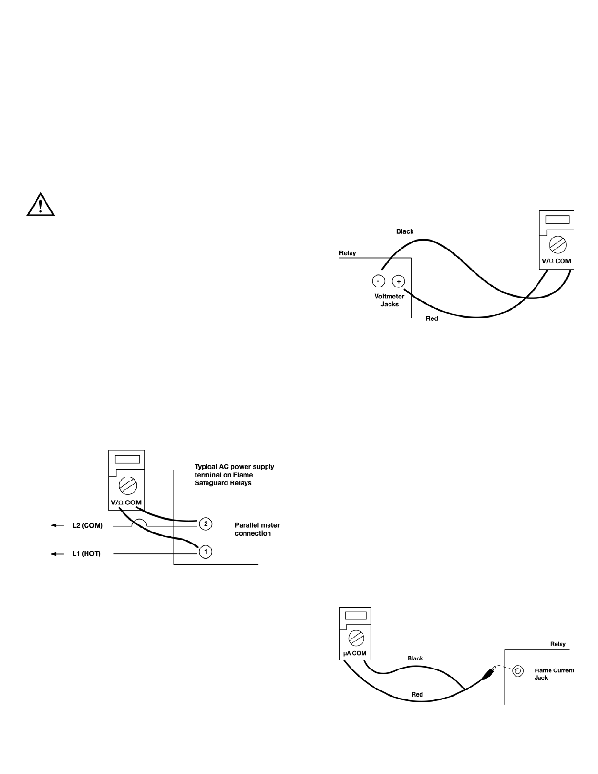
AC Voltage
To determine the voltage of any energized AC circuit up to 300 volts.
proceed as follows:
1. Set range selector switch to AC volts (700 or higher).
2. Connect the red test lead to the V/Ω input and the
black test lead to the common input.
3. Attach the meter leads in parallel with the voltage to
be measured (Fig 1).
4. Read meter display.
DC Voltage
To determine the voltage of any energized DC circuit up to 150 V,
proceed as follows:
1. Set range selector switch to DC volts (400 or higher).
2. Attach the meter leads in parallel with the voltage to
be measured (Fig 2).
3. Read meter display.
NOTE: Fig 2 illustrates how flame circuit voltages (instead of current)
are measured on flame safeguard controls using lead sulfide
photocell detectors. (Suitable lead sulfide detector voltage readings
are 100 - 140 V DC).
Meter connections for checking performance of lead sulfide photocell
with R478B or R4074B relay.
Flame Current Check
The flame current is the best indicator of proper flame detector
application. The check should be done at the time of installation, at
any time service is done on the system, and at least once a month or
sooner while the system is in operation. This will prevent shutdowns
due to poor flame signal.
The test is done by connecting your multimeter in series with the flame
detector using µA (microamp) range and reading the flame signal when
the burner is operating.
Insert the ATLFSG red test lead to the “mAµA” jack and the black test
lead to the “COM” jack on the meter and the mini-plug into the test
jack on the RA890F. This automatically puts the meter in series with the
flame detector.
1. For a flame safeguard relay having a flame current jack, such as
RA89E, F, & G, R890E, F, & G, R4138, R4150, R4181, R4795A,
C, D (Fig 3).
(Fig 1)
(Fig 2)
(Fig 3)
ATLFSG-MAN P. 1

(Fig. 5)
2. Insert cable connector plug into flame current jack. This puts the
meter in series with the flame lead. The system must be operating
and detector sighting flame for current to flow through the meter.
Minimum safe current is 2µA (Fig 4).
RA890F and 0270A sub-base
Location of test jack on the RA890F
3. For a flame safeguard relay without flame current test jack, such
as R890, R485, RA1 90B, RA890B & C, R 178, R407A, R7023, W1
24, hook-up (Fig 5).
4. For pulsing-type relay without a flame current test jack, such as
R4075B and some models of R4138A, hook-up (Fig 5). Use the
20µA selector setting and read direct. To stop cycling, manually
hold in relay 2K (2R in older models) and pull out the
vacuum tube.
NOTE: System must be operating and detector sighting flame for
current to flow through the meter.
ATLFSG-MAN P. 2
(Fig 4)
(Fig 5)
5. For pulsing-type flame safeguard relays with the flame current
jack and push-button for eliminating pulses, used with a
self-checking C7012E flame detector, such as R4138A and
R4181A (Fig 6).
6. Insert cable connector plug into flame current test jack to put
meter in series with flame lead (Fig 6). To stabilize meter reading,
hold relay 2K in with one hand, press test push-button with other
hand, read µA scale and release button. When normal pulsing is
reestablished, release relay 2K. A stable reading, with the
push-button depressed and 2K held in, of 4 to 4-1/2 minroamps
is the minimum acceptable flame current.
CAUTION!
To eliminate the possibility of injury to operator and damage to the
instrument and equipment, the following procedure is recommended.
Exercise care and caution on all ranges, particularly the voltage
ranges, and follow all standard published safety rules and wear
appropriate personal protective equipment (ppe). Misuse, abuse and
carelessness cannot be prevented by any written word and is fully the
operator’s responsibility.
(Fig 6)

Limited Warranty
The AT L FSG is warranted to be free from defects in materials and workmanship
for a period of one year from the date of purchase. If within the limited lifetime warranty
period your instrument should become inoperative from such defects, the unit will be
repaired or replaced at UEi’s option. This warranty covers normal use and does not cover
damage which occurs in shipment or failure which results from alteration, tampering, accident, misuse, abuse, neglect or improper maintenance. Batteries and consequential damage resulting from failed batteries are not covered by warranty.
Any implied warranties, including but not limited to implied warranties of merchantability
and fitness for a particular purpose, are limited to the express warranty. UEi shall not be
liable for loss of use of the instrument or other incidental or consequential damages,
expenses, or economic loss, or for any claim or claims for such damage, expenses or
economic loss. A purchase receipt or other proof of original purchase date will be required
before warra n ty repairs will be rendered. Instruments out of warra n ty will be repaired
(when repairable) for a service charge. Return the unit postage paid and insured to:
1-800-547-5740 • FAX: (503) 643-6322
www.ueitest.com • Email: info@ueitest.com
This warranty gives you specific legal rights. You may also have other rights which vary from
state to state.
ATLFSG
Flame Safeguard Relay Test Kit
Copyright © 2007 UEi ATLFSG-MAN 2/07
 Loading...