

Page 1
1-800-547-5740 • Fax: (503) 643-6322
www.ueitest.com • email: info@ueitest.com
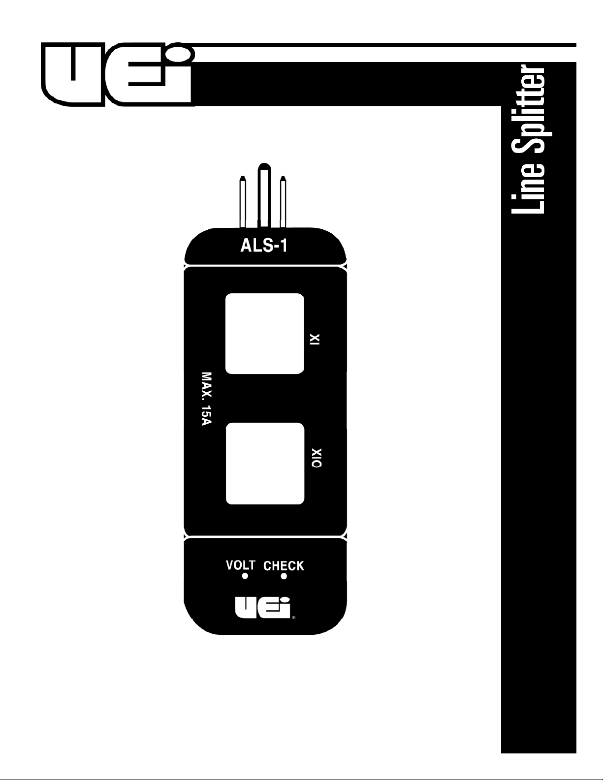
ALS1
INSTRUCTION MANUAL
Page 2

Introduction
Line splitter for clamp-on meters eliminates the need to split electrical
cords or open electrical boxes for current measurements on 120V lines.
Features include
• 1 to 1 and 10 to 1 internal coils for better resolution
• 15A max.
Operating Instructions
Theory of Operation
A magnetic field, proportional to the magnitude of current, surrounds
all current carrying conductors. In an AC circuit the magnetic field will
induce a current. In the jaws of a clamp-on current probe when the
jaws are closed around the conductor.
If both conductors of the circuit are enclosed by the jaws of the probe
the magnetic fields will cancel and no measurement is possible. Most
120V AC appliances use two conductor cords which make it difficult
to isolate a single conductor for measurement. The ALS1 provides
temporary separation of conductors to facilitate measurement
of current.
1. Plug the ALS1 into a grounded type 120V AC receptacle. If a
grounding type receptacle is not available, a 2 to 3 wire adapter
must be used. Maintain ground wire integrity to minimize the
possibility of electrical shock.
2. Plug the appliance line cord into the end of the ALS1 and turn
on the appliance.
3. Place the jaws of the clamp-on current probe through the X1
section of the ALS1. The current being drawn by the appliance
can then be read directly from the indicator of the clampon probe.
4. If the magnitude of the reading obtained in step 3 is less than
one-tenth of the full scale range of the clamp-on current probe,
and difficult to read, place the jaws of the probe through the X10
section. The magnitude of the current drawn by the appliance will
be the reading on the current probe meter divided by ten.
Example: With the range switch of the clamp-on current probe
set to 6 amps, the meter indicates 5.4 amps, and the jaws of the
probe are through the X10 section of the ALS1. The actual current
is 0.54 amps (5.4 amps ÷ 10 = 0.54 amps, or 540mA).
Interpretation of Results
1. Most appliance manufacturers state the rating of an appliance on
the frame, or housing. The rating will be stated either in AMPERES
or WATTS.
2. If the rating is stated in AMPERES then this figure may be
compared with the reading on the clamp-on current probe. A
reading that is significantly LOWER that the manufacturer’s rating
may indicate low line voltage., corroded terminals, or some other
fault, which results in a higher resistance to current. A reading that
is significantly HIGHER than the manufacturer’s rating may indicate
high line voltage, or a partial short in the appliance, which results
in a lower resistance to current.
The line voltage may be easily checked by inserting the test probes
of an AC voltmeter into the VOLT CHECK input jacks on the ALS1.
3. If the appliance rating is stated in WATTS, then multiply the
reading in current (taken directly from the clamp-on probe) times
the line voltage. The product will be the power consumption
in watts.
Example: The clamp-on current probe indicates that 8.5 amperes
is being drawn by the appliance. The line voltage is measured
and found to be 102V AC. The power consumption is 867 watts
(8.5 amps x 102 volts = 867 watts).
A power consumption which is significantly higher, or lower, than
the rated power consumption may be due to the factors given in
section 2, for low or high current readings.
ALS1-MAN P. 1
Page 3

Limited Warranty
The ALS1 is warranted to be free from defects in materials and workmanship
for a period of one year from the date of purchase. If within the limited lifetime warranty
period your instrument should become inoperative from such defects, the unit will be
repaired or replaced at UEi’s option. This warranty covers normal use and does not cover
damage which occurs in shipment or failure which results from alteration, tampering, accident, misuse, abuse, neglect or improper maintenance. Batteries and consequential damage resulting from failed batteries are not covered by warranty.
Any implied warranties, including but not limited to implied warranties of merchantability
and fitness for a particular purpose, are limited to the express warranty. UEi shall not be
liable for loss of use of the instrument or other incidental or consequential damages,
expenses, or economic loss, or for any claim or claims for such damage, expenses or
economic loss. A purchase receipt or other proof of original purchase date will be required
before warra n ty repairs will be rendered. Instruments out of warra n ty will be repaired
(when repairable) for a service charge. Return the unit postage paid and insured to:
1-800-547-5740 • FAX: (503) 643-6322
www.ueitest.com • Email: info@ueitest.com
This warranty gives you specific legal rights. You may also have other rights which vary from
state to state.
ALS1
Line Splitter
Copyright © 2007 UEi ALS1-MAN 8/07
 Loading...