

Page 1

Translation of the original manual,
compiled: 24.02.17
224260010_BA_en_Version_CSU_00
Hydraulic
Rotary Hammer Drill
Type 2 2426 0010
Techn. Doc. No. 262
Illustration can differ from the original
Operation and
Maintenance Manual
Page 2

Hydraulic Rotary Hammer Drill
2 2426 0010
Translation of the original manual,
compiled: 24.02.17
224260010_BA_en_Version_CSU_00
Page 1 of 18
Directory
Page
Signal Word and Symbol Definition 2
Technical Specification 3
Use 3
Product Description 4
Identification 4
Installation 5
Startup 6-7
Underwater use 7
Basic Safety Instructions 8
Employer‘s Obligations 8
Operator‘s Obligations 8
Explanation of Symbols for Protective Equipment and for Accident Prevention 9
Safety Instructions for avoiding Safety Hazards 10-13
Service and Maintenance 14-15
Disassembly – Re-assembly 15
Storage 16
Disposal 16
Environmental Regulations 16
Troubleshooting 16
Warranty and Liability
17
Sc
ope of delivery 17
Declaration of Conformity 18
CS Unitec, Inc. • Toll-free: 800-700-5919 • Ph: 1-203-853-9522 • Email: info@csunitec.com • www.csunitec.com
Page 3

Hyd r a u l ic Rotary Hammer Drill
2 2426 0010
Translation of the original manual,
compiled: 24.02.17
224260010_BA_en_Version_CSU_00
Page 2 of 18
Signal Word and Symbol Definition
The signal words and symbols used in the technical documentation (safety instructions, operating booklet,
etc.) have the following meaning:
WARNING
–
Read the operation and maintenance manual
It is imperative to familiarize with this operation and maintenance manual and its safety
instructions before starting the machine. Stick to the operating processes and avoid
accidents due to improper use of the machine.
This symbol has
the following
meaning:
DANGER – Indicates an immediate danger, which causes serious injuries to any person
or even death, if not avoided.
WARNING – Indicates a threatening danger, which can cause serious injuries to any
person or even death, if not avoided.
CAUTION – Indicates a danger or unsafe procedure which can cause injuries to any
person or material damages, if not avoided.
NOTICE – Indicates a potentially dangerous situation which can cause damage to the
product or its surroundings, if not avoided.
WARNING – hot surface
Risk of burns when touching the surfaces having this warning sign!
WARNING – explosive atmosphere
Air and flammable substances can mix and result in an explosive atmosphere. In areas
exposed to explosion hazards, supplementary instructions and directives apply. Observe
the safety instructions of the employer as well.
WA
RNING – explosive material
Caution should be exercised when working with explosive material or in its surrounding
area.
PROHIBITION – No naked flame, fire, or ignition source and no smoking
Prevent from fire and explosion hazards, which can be caused by naked flame, open
ignition source or by smoking.
Eating and drinking forbidden – The prohibition sign forbids the consumption of food.
REQUIREMENT – Observe the instruction
Ensure that the operation process is adhered to and avoid accidents and expensive break
down times due to improper use of machines, devices and tools.
By using the mandatory sign you refer to the adherence of operation instructions.
This symbol has
the following
meaning:
NOTICE – Gives recommendations and important hints for handling the product
IMPORTANT – Indicates application advice and other particularly useful information.
REMARK:
In each case the used symbol does not replace the safety text. The text must always be read fully. In some
cases other symbols will be used with the signal words.
CS Unitec, Inc. • Toll-free: 800-700-5919 • Ph: 1-203-853-9522 • Email: info@csunitec.com • www.csunitec.com
Page 4
Hyd r a u l ic Rotary Hammer Drill
2 2426 0010
Translation of the original manual,
compiled: 24.02.17
224260010_BA_en_Version_CSU_00
Page 3 of 18
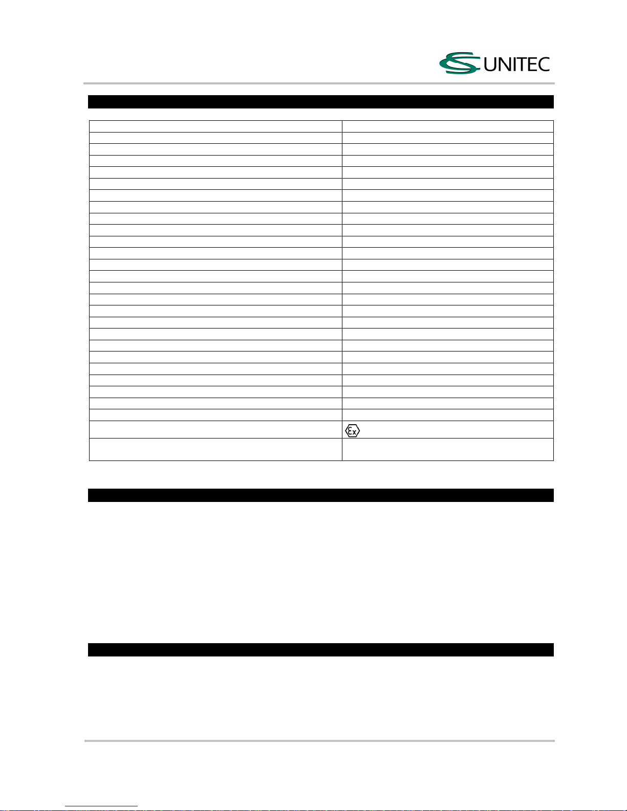
Technical Specification
Operating pressure 1160 – 2030 PSI
Power 1.6 HP
Free speed 500 +/- 50 rpm
Speed under load 450 +/- 50 rpm
Percussion under load 3400 blows/min
Percussion energy 2 J
Volume flow 4 – 6.6 gallons/ min
Drilling capacity in concrete 0.19685 – 1.102 inches
Drilling capacity in concrete of medium hardness 0.4728 dia. = 2.0853 cu. in =11.82 inches/ min
Optimum drilling capacity 0.472 – 0.787 inches
Drilling in steel with quick-release chuck 0.19685 – 0.5118 inches
Drilling in wood with quick-release chuck 0.19685 – 1.1811 inches
Hydraulic connection machine SAE PORT No. 8 (3/4 x 16 UNF – 2 B)
Hydraulic connection hose set Flat-Star A250-OM/OF-1/2”BSP
Hydraulic fluid Hydraulic oil
Hydraulic circuit Open circuit
Oil filtering ISO purity degree 20/18/13
Temperature of oil - 34 °C to + 82 °C
Viscosity of oil > 13 centistokes
Water connection ball valve R ¼"
Shank SDS Plus
Dimensions, L x H x W 18” L x 10 ¼” H x 4” W
Weight (without hoses) 18 lbs
Sound pressure level L
pA
(1)
92 db(A)
Sound power level LWA 101 db(A)
Vibration
(2)
4.5 m/s²
ATEX Classification II 2G c T5
(1)
Remark: Measurement acc. to DIN EN ISO 15744
(2)
Remark: Measurement acc. to DIN EN ISO 28927-5
Me
ssunsicherheit K: 3 dB (A)
Messunsicherheit K: 1.5 m/s2
The performance specifications are guide values only, they depend basically on the application, the
working pressure and the accessories used.
Intended Use
SPITZNAS machines are designed for industrial use only.
Only trained, skilled personnel are allowed to operate the machine.
The hammer drill serves for hammer drilling into:
concrete, stone and masonry
and when rotary drilling only, into:
Steel, stainless steel, non-ferrous metal, cast iron, wood and plastic
It can be used for:
Construction industry (building, rebuilding and renovation), workshop, chemical industry / refineries,
nuclear industry and underwater.
Improper Use
Any use deviating from the intended use as described is considered to be improper use.
Working without personal protection equipment.
Using the machine in an inadmissible area.
Drilling self-flammable material.
Page 5
Hyd r a u l ic Rotary Hammer Drill
2 2426 0010
Translation of the original manual,
compiled: 24.02.17
224260010_BA_en_Version_CSU_00
Page 4 of 18
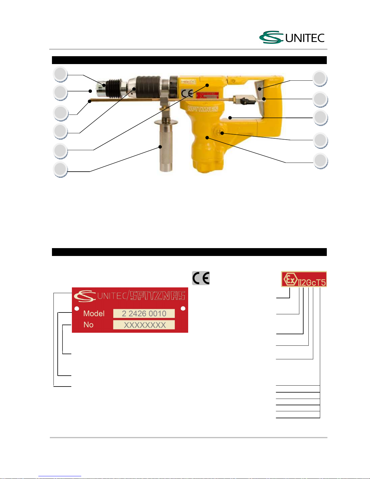
Product Description
Fig. 1
1 Valve trigger
2 Motor housing
3 Hydraulic connection (P)
4 Hydraulic connection (T)
5 Gear housing
6 Adjusting sleeve
7 Sliding sleeve
8 Shank
9 Second Handle
10 Flush connection
11 Depth gauge
Sliding clutch for prevention of overload and accidents, gear capsuled in a dustproof way, lubrication
centralized and permanent, rotatable second handle with water cooling and drilling depth gauge.
Identification
Type sign Explanation of ATEX Identification
Specification
Serial number (1. u. 2. figure refer to the
year of manufacture/ following figures refer
to the series)
Type description
Company name and address
Specification for prevention
from explosion (ATEX)
Machine group II
Explosive atmospheres
e. g. Industry
Category 2
High level of safety
Ex-Atmosphere G
Gas, vapor and mist
Explosion protection c
Constructional safety
Temperature class T
Surface temperature limit
450°C T1
300°C T2
200°C T3
135°C T4
100°C T5
85°C T6
CS Unitec, Inc. • Toll-free: 800-700-5919 • Ph: 1-203-853-9522 • Email: info@csunitec.com • www.csunitec.com
Page 6
Hyd r a u l ic Rotary Hammer Drill
2 2426 0010
Translation of the original manual,
compiled: 24.02.17
224260010_BA_en_Version_CSU_00
Page 5 of 18
Installation
Hydraulic system requirements
The following is required for an optimum performance of the hydraulic rotary hammer drill:
Provide a volume flow of 4 – 6.6 gallons/ min at an operating pressure of 1160 – 2030 PSI.
The system should not have more than 247 PSI back pressure.
The hydraulic system should have sufficient heat rejection capacity to limit the maximum oil temperature
to 140 °F at the maximum expected ambient temperature.
It is recommended:
That filter elements are sized for a volume flow of at least 30 gallons/ min for cold temperature startup
a
nd for maximum dirt holding capacity.
The hydraulic system should have a minimum of 10 to 25 micron of full-flow filtration.
Connecting the hydraulic supply to the hydraulic rotary hammer drill
The machine is designed for an open circuit.
Check:
The circuit type (open circuit or closed circuit), before connecting the machine.
That all hose couplings are clean, before connecting the hoses.
That there are no signs of leakage.
That the machine is clean and dry.
That all assembly parts and fixing elements are firmly fixed, respectively tight.
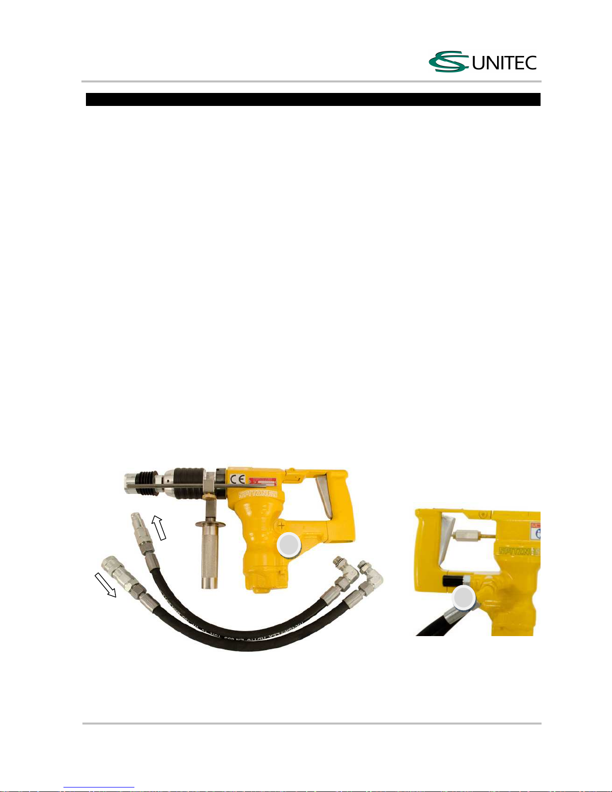
The recommended hose size is from 0.472 to 0.629 inches for the inner diameter and between 590 and
1181 inches for the length. Always connect the return hose first and disconnect it at last (see fig. 2).
P
(Pump connection) = Supply
T (Tank connection) = Return
flow
Fig. 2
(IN) P
(OUT) T
(IN) P
(OUT) T
CS Unitec, Inc. • Toll-free: 800-700-5919 • Ph: 1-203-853-9522 • Email: info@csunitec.com • www.csunitec.com
Page 7

Hyd r a u l ic Rotary Hammer Drill
2 2426 0010
Translation of the original manual,
compiled: 24.02.17
224260010_BA_en_Version_CSU_00
Page 6 of 18
Startup
Hammer drilling
Fig. 3.1: Pull back the adjusting sleeve and lock it in clockwise direction.
Fig. 3.1 Fig. 3.2
Fig. 3.2: Pull back the sliding sleeve and insert the drill. Turn until the sliding sleeve returns into the initial
position. Press the machine against the work surface before switching it on, otherwise the tool will not
hammer. If the drill sticks in the hole, withdraw and reinsert it several times when drilling.
Do not exert undue pressure on the machine - this will not increase its performance. Just position the bit and
guide it into the hole. For hammer drilling do not use any quick-release chuck. (see fig. 3.4 and 3.5).
Fig. 3.3: When starting to drill in brittle material (tiles, etc.): Unlock the adjusting sleeve. Hold and continue to
d
rill the hole, then switch off the machine briefly and relock the adjusting sleeve.
Fig. 3.3
Fi
g. 3.4
CS Unitec, Inc. • Toll-free: 800-700-5919 • Ph: 1-203-853-9522 • Email: info@csunitec.com • www.csunitec.com
Page 8

Hyd r a u l ic Rotary Hammer Drill
2 2426 0010
Translation of the original manual,
compiled: 24.02.17
224260010_BA_en_Version_CSU_00
Page 7 of 18
Ro
tary drilling only
Fig. 3.4: Unlock the adjusting sleeve. It is possible to use a quick-release chuck at this setting.
Quick-release chuck: Spitznas order no.: 9 2902 0200
Adapter SDS-plus for quick-release chuck: Spitznas order no.: 9 2902 0210
(9 2902 0200 and 9 2902 0210 not contained in the scope of delivery.)
Standard spiral drills can be used with the quick-release chuck. (see fig.3.5).
Fig. 3.5
Fig. 3.6
Drilling in explosive surrounding
Fig. 3.6: The drill must be water cooled to avoid sparks.
Water connection at the ball valve.
Placing the machine into the carrying case
Make sure the adjusting sleeve is locked at the setting „rotary hammer drilling“.
Side handle
this can be turned through 360° and locked in any desired position.
Depth gauge
Press unlock button, adjust depth gauge and release button.
Cold weather operation
If the rotary hammer drill has to be used during cold weather, pre-heat the hydraulic fluid at low motor speed.
If the normally recommended fluids are used, the fluid temperature should be 50 °F (82 centistokes) or
more, before operating the machine. Too high viscosity damages the hydraulic motor (the hydraulic
system).
Underwater Use
Before underwater operation
Ensure that:
All hydraulic hoses are properly connected.
The machine is tested for leakage and for the functioning of all parts.
Notice: Keep in mind that 10 meter water depth corresponds to 1 bar.
When working in greater depths match the diameter of the supply and exhaust hose appropriately.
After underwater operation
Clean and dry the machine with compressed air.
Spray all moving parts with multi-oil-spray: Spitznas order no. 9 9902 0120 (or similar).
CS Unitec, Inc. • Toll-free: 800-700-5919 • Ph: 1-203-853-9522 • Email: info@csunitec.com • www.csunitec.com
Page 9

Hyd r a u l ic Rotary Hammer Drill
2 2426 0010
Translation of the original manual,
compiled: 24.02.17
224260010_BA_en_Version_CSU_00
Page 8 of 18
Basic Safety Instructions
Read operation instructions/safety instructions!
Before working on or with the tool, read the safety instructions and follow the instructions
during operation.
Do not modify the machine or the machine tools and accessories after receipt. Any constructive changes or
modifications need the manufacturer`s acceptance and have to be in compliance with the safety
instructions. Use the machine only for its determination. Consider the technical data of the equipment and
the ambient temperatures. Pay attention to labels, restrictions of use and special instruction notes on the
machine tools and the machine itself. Check regularly that the type plate and symbols on the machine are
legible. If necessary, contact the manufacturer to replace them. Only operators with technical knowledge,
trained by authorized responsible technical personnel, may install, adjust, operate, transport and store the
machine.
Employer’s Obligations
Generally, the employer is responsible for the faultless condition/operation of the machine and the
adherence to the safety regulations. The machine is designed and manufactured according to the technical
safety regulations. However, using it, there is still a risk of accidents to the operator or third parties or
damage to the machine or other objects. All current regulations and specifications, which apply to the site of
operation in regards to accident prevention, installation of electrical and mechanical systems as well as radio
interference must be considered.
IMPORTANT - The employer must make sure that…
risk assessment is carried out for the specific risks, which can occur due to any operation of the
machine,
the function of the safety equipment is regularly checked,
the safety symbols and safety notes on the machine/ device and in the operating instruction booklet are
considered,
the safety instructions and the operating instruction booklet are available completely and in legible
c
ondition on site with the machine.
The employer is obliged to allow personnel to work on the machine only, who:
Are familiar with the basic work environment safety rules and accident preventing regulations. Also,
those persons must have been instructed in the correct use of the machine,
have read and understood the safety and warning notes in the operating instruction booklet as well as all
the other documentation pertaining to the machine,
have been tested at regular intervals in regards to their safety-conscious operation.
Safety-conscious working
Additionally to the safety instructions in this manual and the intended use, the following safety regulations
have to be considered:
Accident prevention instructions, safety and operation regulations,
explosion protection directives,
safety regulations for the operation with hazardous material,
effective norms and laws.
Operator’s Obligations
All persons who are assigned to work with the machine are obligated to:
Pay always attention to the basic safety and accident preventing regulations,
read always and follow the safety and warning notes in the operating instruction booklet.
Page 10

Hyd r a u l ic Rotary Hammer Drill
2 2426 0010
Translation of the original manual,
compiled: 24.02.17
224260010_BA_en_Version_CSU_00
Page 9 of 18
Explanation of Symbols for Protective Equipment and for Accident Prevention
Use protective clothes – Protective clothes are necessary for diverse applications, e.g.
protection against chemicals, heat and cold. Provide appropriate protective clothes to your
staff and identify this requirement by convincing signage.
Use head protection – Keep staff and visitors from head injury. Provide enough safety
helmets and identify the obligation for using safety helmets by appropriate mandatory signs.
Use eye protection – whether goggles, laser safety goggles or etc. –
identify areas where eye protection has to be used, by appropriate mandatory signs.
Use ear protection –
Capsule hearing protectors or hearing protectors have to be used for ear
protection, depending on the sound intensity at the work place. Provide appropriate ear
protection and identify the obligation for using ear protection by appropriate mandatory signs.
Use foot protection – Foot injuries by vehicles, objects, hot material or hazardous
substances can be avoided by appropriate protective shoes. Equip your staff with
appropriate protective shoes and identify those requirements properly.
Use hand protection – Identify convincingly the safety requirement „Use hand protection“
by a gloves sign, respectively a gloves symbol.
Use respiratory protection – Ensure that the specified protection equipment is available
and that it is used. Identify by mandatory signs, where and when respiratory masks are
required.
Danger Zones
Operational
condition
-------------------Life phase
Normal function Malfunction Improper use Expected
use
Transport Transport of the machine
in an inoperable condition
Drop of the
machine
Transport of the
machine in an
operable condition
unknown
Startup Equipment of the machine
with the designated drill bit
unknown Equipment of the
machine with grinding
pins or other tools
unknown
Operation Machine works only with
actuated valve
Machine moves the drill
bit
Machine runs
without
intended
actuation
Machine blocks
Valve is blocked in
actuated condition
unknown
unknown
Maintenance Regular cleaning Breakdown of
the machine
unknown unknown
Hazard notes regarding the hydraulic powerpack: refer to the manufacturer
CS Unitec, Inc. • Toll-free: 800-700-5919 • Ph: 1-203-853-9522 • Email: info@csunitec.com • www.csunitec.com
Page 11

Hyd r a u l ic Rotary Hammer Drill
2 2426 0010
Translation of the original manual,
compiled: 24.02.17
224260010_BA_en_Version_CSU_00
Page 10 of 18
Safety Instructions for Prevention of Workplace Hazards
WARNING – The following applies unless otherwise stated in the machine’s operating
instructions booklet: The machine is not insulated to protect against an electrical power surge.
CAUTION – risk of injury!
Hands may be crushed, seized or otherwise injured.
Keep your hands away from areas which are marked with this symbol.
CAUTION – risk of injury!
Remove all sources of danger which could lead to slipping, tripping or falling (e.g. slippery
surface, hoses, cables).
Keep the work area clean and tidy.
PROHIBITION – Eating, drinking and smoking are forbidden during operation.
WARNING – Explosion hazard!
Operate the machine only according to the intended use.
The machine is designed for the use in areas exposed to explosion hazards as well.
The generation of heat and –eventually- sparks at the drilling point is characteristic for drilling
certain material. Therefore the drilling point has to be cooled continuously.
Consider the following:
Valid local explosion protection directives.
Technical specification of the machine.
Markings on the machine.
Avoid the generation of sparks.
When operating the machine, do not push or beat against other material
a
nd hold the machine firmly and safely by hand.
Do not slide the machine over the ground.
If heat generation exceeds the specified surface temperature, the machine has to be
stopped instantly. It may be re-started only after having eliminated the cause for the fault.
The work area and the other close working areas should always be protected from sparks.
Flammable and explosible material has to be removed from the work area before starting
work. Among others, this relates to dust deposits, cardboard, packing material, textile, wood
and wooden splints, but also flammable fluids and gas.
Ensure adequate lighting.
Be extra careful in unfamiliar surroundings. There is a risk of hidden hazards such as electric lines or other
supply lines. Make sure when operating the machine that no electrical cables, gas pipes or similar could be
damaged. Use suitable and personal protective equipment.
CS Unitec, Inc. • Toll-free: 800-700-5919 • Ph: 1-203-853-9522 • Email: info@csunitec.com • www.csunitec.com
Page 12

Hyd r a u l ic Rotary Hammer Drill
2 2426 0010
Translation of the original manual,
compiled: 24.02.17
224260010_BA_en_Version_CSU_00
Page 11 of 18
Safety Instructions for Prevention of Hazards caused by Hydraulic
WARNING
– Hydraulic can cause severe injury. Before working on the tools (e.g.
installation, changing accessories or machine tools, prior to a long standstill, maintenance,
etc.) depressurize hydraulic equipment.
CAUTION – Risk of injury by whipping hydraulic hose.
Check hydraulic hoses, connection components and fittings regularly for any damages and
proper fixture.
When connecting / disconnecting the machine to / from the hydraulic supply, please pay careful attention
not to actuate the valve while doing so. Never remove a pressurized hydraulic hose. Always switch the
power supply off first and then depressurize the machine.
The maximum operating pressure according to the technical specification must not be exceeded.
A pressure regulator should be installed, which regulates the pressure before it reaches the machine.
Never direct a hydraulic hose at yourself or anyone else. Do not carry or pull the machine at the hydraulic
hose.
Safety Instructions for Prevention of Operating Hazards
Before starting work make sure that the hands are protected against: impacts, crushing, hits, cuts, abrasions
and heat. The operating and maintenance personnel must be physically able to handle the bulk, the weight,
the power and/or the torque of the machine. Do not use the machine if you have taken any medication or
drugs, after drinking alcohol or with any other constraints on your vision, reaction time or judgment. Work in
the best possible position so that you can react with both hands to any normal or unexpected movements of
the machine. Maintain a balanced body position and secure footing in order to avoid improper strain and to
be able to support the reaction torque of the machine. If you cannot safely support the reaction torque of the
machine, use a torque reaction bar (e.g. linear stand, telescopic arm, holding fixture/ holder-on, support grip).
Additionally consider the following:
Operate the machine only after having carefully read the operation manual.
Use appropriate drill bits.
The work place has to be secured according to the instructions, in order to avoid injury due to flying
p
articles.
The machine is for hand-held operation only.
Consider the producer’s specification when selecting the drill bit.
Check the secure fixing of the drill chuck and the drill bit before starting work.
If the machine blocks, then higher reaction torques can occur. Blocking can be caused by: overload,
tilting of the drill bit in the work piece or when penetrating the material. Do not let the drill bit rumble on
the work piece, as this increases the vibration. When drilling through-holes, reduce the contact pressure
shortly before the drill bit penetrates the material (for thin work pieces there is the risk that the drill
hitches and lifts the work piece.)
It is possible that the drill bit keeps on running after the machine has been switched off. Wait until it
stops and deposit the hand-held machine in a secure position.
Never stop the drill chuck or the drill bit by hand.
CS Unitec, Inc. • Toll-free: 800-700-5919 • Ph: 1-203-853-9522 • Email: info@csunitec.com • www.csunitec.com
Page 13

Hyd r a u l ic Rotary Hammer Drill
2 2426 0010
Translation of the original manual,
compiled: 24.02.17
224260010_BA_en_Version_CSU_00
Page 12 of 18
Safety Instructions for Prevention of Entanglement Hazards
CA
UTION – Loose clothing, personal jewellery (e.g. necklace), scarves/ ties, long hair or
gloves can get caught up in the machine tool or accessories and thus cause severe injuries
(lack of breath by throttling, abrasions, skin injuries and/ or cuts and lacerations).
Wear suitable, close fitting work clothing!
Wear a hair net, if you have long hair. When handling the machine, jewellery, necklaces, etc.
h
ave to be removed or are forbidden, respectively.
Safety Instructions for Prevention of Noise Hazards
Always wear hearing protection
– This refers to the operator, as well as to any other
person within the vicinity of the machine. Observe the instructions of the employer and of the
professional association.
During operation high noise levels can cause permanent hearing problems such as tinnitus (ringing, buzzing,
whistling or humming in the ears), hardness of hearing or even deafness.
If possible, use sound absorbing material, in order to avoid ringing noise at the work pieces.
Safety Instructions for Prevention of Vibration Hazards
Vibrations can cause damage of nerves and blood vasculares in hands and arms.
Wear warm clothing and keep your hands warm and dry when working in cold conditions. Exercise
hands and fingers regularly.
Use stands and/or weight balancers, if possible.
When using a support (e.g. stand) make sure the machine is securely fixed. If no support is used, hold
t
he machine with light but safe grip in order to support the tool’s reaction torque. The tighter the grip the
greater the risk of vibrations.
Mount the machine as described in the operating instruction booklet in order to avoid unusually high
vibrations.
Stop work immediately, if you feel any numbness, tingling, pain or whitening of fingers or hands. Inform
the employer and consult a doctor.
Safety Instructions for Prevention of Dust and Fume Hazards
Wear respiratory protection - Use respiratory protection as instructed by your employer
and as required by occupational health and safety regulations. Potentially generated or
disturbed dust and fumes in the working environment or from using the machine can cause
illness (e.g. cancer, birth defects, asthma and/ or dermatitis).
Carry out risk assessment regarding dust and fume hazards and implement appropriate measures.
Keep the working place clean.
Keep in mind that working in certain materials may create dust and fumes causing a potentially
explosive atmosphere.
CS Unitec, Inc. • Toll-free: 800-700-5919 • Ph: 1-203-853-9522 • Email: info@csunitec.com • www.csunitec.com
Page 14

Hyd r a u l ic Rotary Hammer Drill
2 2426 0010
Translation of the original manual,
compiled: 24.02.17
224260010_BA_en_Version_CSU_00
Page 13 of 18
Re
mark: Some material may have toxic coatings.
Please pay particular attention to avoid skin contact and breathing in, when working with those materials.
Always use a protective mask. Ask your material supplier about special safety instructions and stick to them.
Safety Instructions for Prevention of Projectile Hazards
Wear impact
-
resistant safety goggles
–
This refers to the operator, as well as to the persons
within the vicinity of the machine. Assess and determine the grade of protection required
depending on the individual case. The risks to others should also be assessed at this time.
On overhead work, wear a safety helmet. If a work piece, accessories, inserted tools, or the
tool itself breaks, there is danger from high velocity projectiles.
Check all parts for damages before using the machine.
Replace damaged parts immediately.
When working on brittle material make sure that you are protected against harmful splinters.
Safety Instructions for Prevention of Accessory Hazards
Use only machine tools, accessories and consumables, which are recommended by the manufacturer. Make
sure choosing the correct size and the correct type. Use only accessories, which are in proper condition.
CA
UTION – Injury due to carelessness!
If the machine is fixed to suspension equipment make sure that it is secure. Never hang the
machine onto the supply line.
Separate the machine from any external energy source before changing the machine tool
o
r any accessory.
Avoid direct contact with the machine tool during and after use as it can be
hot or sharp.
Wear protective gloves when changing a tool or an accessory!
N
otice: Defective/ inappropriate gloves can lead to injury. Wear only proper hand protection,
adapted to the work place requirements.
WARNING – Explosion hazard!
When operating the machine in areas exposed to explosion hazards, use only accessories,
respectively devices, which are ATEX approved and specified.
Safety Instructions for Prevention of Transport Hazards
ATTENTION – Improper Transport, injury due to parts falling down!
Damage of the machine!
Separate the machine form any external energy source before transportation.
Check that the machine is undamaged and in proper condition.
Never carry the machine at the supply line.
We
ar worker’s protective shoes!
CS Unitec, Inc. • Toll-free: 800-700-5919 • Ph: 1-203-853-9522 • Email: info@csunitec.com • www.csunitec.com
Page 15

Hyd r a u l ic Rotary Hammer Drill
2 2426 0010
Translation of the original manual,
compiled: 24.02.17
224260010_BA_en_Version_CSU_00
Page 14 of 18
Service and Maintenance
Basic Safety Instructions:
WARNING – Maintenance and repair work on hydraulic equipment.
Hydraulic can cause severe injury. Observe legal regulations. Take precautions for persons
and environment.
Additionally, observe the following:
Secure the machine against unintentional starting and let the machine cool down to the
a
mbient temperature
Protection against tipping, tumbling or falling down when assembling/ disassembling the
machine/parts.
CAUTION – Skin exposure to hazardous dusts may cause severe dermatitis. Dust at the
work place can be raised during the maintenance procedure and can be inhaled.
Clean the machine and the work place before maintenance work.
WARNING – Danger of explosion! Generation of sparks during maintenance work!
Consider local safety regulations. Avoid use of force when disassembling and assembling
the machine. Always do maintenance work outside hazardous medium.
PROHIBITION - Eating, drinking and smoking are forbidden during maintenance and repair
work
NOTICE
– Use only
original SPITZNAS spare parts
, in order to avoid damages.
Otherwise you risk a decrease in machine performance and an increase in maintenance
work. Check the adherence to the technical specifications according to the operation manual
after each maintenance work.
IMPORTANT – There is no warranty for damages and liability is disclaimed, if non-original
spare parts are used.
Maintenance Instruction
Generally, hydraulic machines need little maintenance. If these rules are followed, the machine will have
the expected durability and high reliability. Service life and performance of the machines are decisively
determined by:
The purity degree of the hydraulic oil
The lubrication conditions and maintenance
The r
egular control of the hydraulic filter/ the hydraulic fluid, as well as the regular checking of
the machine with regards to external damages.
Disassembly and re-assembly of the machine have to be executed by qualified staff only. Incorrect assembly
can lead to danger of accident for the operator and to defects on the machine. Additionally to the measures
described before, it is a must to check the grease in the gear and to fill it up or replace it, if necessary. The
correct quantity of grease (20 g) is very important with regard to good lubrication and low warming.
Grease: SPITZNAS order number 9 9902 0130 (400 g); 9 9902 0250 (100 g)
CS Unitec, Inc. • Toll-free: 800-700-5919 • Ph: 1-203-853-9522 • Email: info@csunitec.com • www.csunitec.com
Page 16

Hyd r a u l ic Rotary Hammer Drill
2 2426 0010
Translation of the original manual,
compiled: 24.02.17
224260010_BA_en_Version_CSU_00
Page 15 of 18
Fu
rthermore we recommend a general overhaul of your hydraulic rotary hammer drill once a year at the
manufacturer, as well as a regular maintenance of the hammer mechanism.
Follow the procedure:
Loosen the socket head screws item 1 and remove the cover item 3 (see fig. 4).
Spray all moving parts with multi-oil-spray: Spitznas order no.: 9 9902 0120 (oder similar).
Replace all sealings item 2, 4 and 5, re-assemble the cover and tighten the screws.
It
em Qty. Order number Description
1 2 9 1112 2020
Socket head
screw
2 2 9 1908 1950 Sealing U shape
3 1 2 2404 4090 Cover
4 1 9 1901 3500 O-Ring
5 1 2 2404 4190 Sealing
Fig. 4
After completing maintenance and repair work and before restarting production make sure that…
all materials, tools and other equipment which are required for maintenance or repairs have been
removed from the work area of the machine,
any fluid leaks have been removed,
all safety devices on the machine have proper function,
fixtures of screw connections are tight,
removed covers, screens or filters were reinstalled.
T
he employer ensures that all maintenance, inspection and assembly work is done by authorized and
qualified experts.
Disassembly- Re-assembly
Maintenance and repair
Disassembly and re-assembly should be done according to the exploded views, respectively the sectional
drawings (see repair instruction).
All work regarding disassembly and re-assembly, have to be executed by SPITZNAS or skilled staff only.
DANGER
– Working with the machine without appropriate preparation and disregarding of
instructions. Shut down the machine properly and let it cool down to the ambient temperature.
NOTICE – Special instructions apply for the repair of explosion-proof machines.
Retrofits or modifications of the machine need the manufacturer’s acceptance.
The explosion-proof machine is designed in the type of protection „c“ constructive safety.
All work executed on the machine, influencing the explosion protection, e. g. repairs with
mechanical machining, require an approval of an authorized expert or have to be done by the
manufacturer.
The internal structure must remain unmodified.
1
2
3 4
5
Page 17

Hyd r a u l ic Rotary Hammer Drill
2 2426 0010
Translation of the original manual,
compiled: 24.02.17
224260010_BA_en_Version_CSU_00
Page 16 of 18
Storage
Unused machines and machine tools should be kept in a dry, closed room.
Keep them free from damaging influences such as damp, frost or large temperature fluctuations as well as
mechanical damage. Always store the machine in a way that important machine instructions, e. g. on
stickers and signs, are legible.
NOTICE – Always connect the loose ends of the hoses with each other, if possible.
Disposal
Dispose of machine and worn out/defective machine tools according the local/national regulations. Fully
d
isassemble the machine for the necessary disposal. Separate materials according to local environmental
specifications. Dispose environmentally hazardous greasing, cooling or cleaning agents in order to avoid
environmental contamination.
Environmental Regulations
When working on or with the equipment, it is imperative to observe all legal requirements in regards to
waste-disposal and proper recycling. In particular during installation, repair and maintenance work, water
damaging agents, such as
lubricating grease and oil,
hydraulic fluid,
coolant,
solvent containing cleaning agents
must not leak into the ground or reach the sewage system.
These materials must be stored, transported, contained and disposed of in suitable containers!
Troubleshooting
The following table shows possible problems and their causes:
P
roblem Cause Remedy
a
Machine does not
start
Not connected to hydraulic supply
Defective hydraulic hoses or quick
couplings
Connect and open the hydraulic line
Replace hydraulic hoses or quick
couplings
b
Machine keeps on
running after
releasing the safety
lever control
Hydraulic hoses inverted Connect hydraulic hoses correctly
c
Low speed Too little operating pressure
Too small hose diameter
Too little volume flow
Too high back pressure
Increase operating pressure
Choose larger hose diameter
Increase volume flow
Reduce back pressure
d
Speed too high Too high operating pressure
Too high volume flow
Adjust to max. operating pressure
(see technical specification)
Reduce volume flow
e
Hydraulic fluid
leaking
Wrong hydraulic fluid
Damaged sealings
Use appropriate hydraulic fluid
Ensure sufficient cooling
Replace sealings
g Other problems Contact authorized expert company
We ask you to send the machine to the supplier, if necessary.
Page 18

Hyd r a u l ic Rotary Hammer Drill
2 2426 0010
Translation of the original manual,
compiled: 24.02.17
224260010_BA_en_Version_CSU_00
Page 17 of 18
Warranty and Liability
Unless otherwise specified, our „General Sales Terms” apply. Warranty and liability claims in regards to
persons or equipment damages are invalid, if one or more of the following causes apply:
Improper use of the machine,
improper assembly, startup, operation or maintenance of the machine,
operation of the machine with defective safety devices or improperly fixed or non-functioning safety and
protection devices,
not considering of the instructions in the operating instruction booklet concerning transport, storage,
a
ssembly, startup, operation, maintenance and setting up of the machine,
independent structural alterations or settings on the machine beyond the intended purpose,
inadequate supervision of wear parts,
improperly carried out repairs, inspections or maintenance,
catastrophic cases due to foreign objects, acts of god or other reasons which are beyond our control.
Scope of Delivery
Check, if the scope of delivery is complete:
1 Operation and Maintenance Manual
1 Hydraulic Rotary Hammer Drill
Included and supplied machine accessories: 1 carrying case, 1 protective cap
CS Unitec, Inc. • Toll-free: 800-700-5919 • Ph: 1-203-853-9522 • Email: info@csunitec.com • www.csunitec.com
Page 19

Hyd r a u l ic Rotary Hammer Drill
2 2426 0010
Translation of the original manual,
compiled: 24.02.17
224260010_BA_en_Version_CSU_00
Page 18 of 18
D e c l a r a t i o n o f c o n f o r m i t y
as defined in the European Union Machine Directive 2006/42/EC and in the
EU-ATEX-Directive 2014/34/EU for usable machines
We, the company
SPITZNAS Maschinenfabrik GmbH, Fellerstraße 4, 42555 Velbert–Langenberg,
declare that the following product
Description: Hydraulic Rotary Hammer Drill
Model: 2 2426 0010
in the version supplied by us, complies with the European Union Machine Directive 2006/42/EC and
the EU-Directive 2014/34/EU (ATEX – group II, category 2, G c T5).
Applied harmonized norms are:
DIN EN ISO 12100
DIN EN ISO 11148-5
DIN EN 1127-1
DIN EN 13463-1
DIN EN 13463-5
According to section 13 (1) b) ii) of the Directive 2014/34/EU the technical documentation is
deposited under reference No. 557/Ex-Ab 2237/14 at the following office:
TÜV Rheinland Industrie Service GmbH
Moltkeplatz 1, 45138 Essen
(Registration No. 0035 for the scope of
the Directive 2014/34/EC)
Name of the authorized person for documentation: Mr. Simon Witt
Address of the authorized person for documentation: see manufacturer’s address
42555 Velbert, 24.02.17
CS Unitec, Inc. • Toll-free: 800-700-5919 • Ph: 1-203-853-9522 • Email: info@csunitec.com • www.csunitec.com
Page 20

Tra
nslation of the original manual,
compiled: 24.02.17
224260010_BA_en_Version_CSU_00
22 Harbor Ave, Norwalk, CT 06850 USA
Toll-free: 1-800-700-5919 (USA & Canada)
Phone: 203-853-9522 (outside USA & Canada)
Fax: 203-853-9921
E-Mail: info@csunitec.com Internet:
www.csunitec.com
 Loading...