

Page 1

Pneumatic
Drill
Types 2 1310 0010
2 1310 0020
2 1311 0010
Techn. Doc.-No. 207
Illustration can differ from the original
Operation and
Maintenance Manual
ne_010011312_02_010001312 80.30.52 :delipmoC
CS Unitec, Inc 22 Harbor Ave USANorwalk, CT 06850
Phone: (203) 853 9522 Fax: (203) 853 9921 info@csunitec.com
Page 1 of 20
Page 2
Pneumatic
Drill
2 1310 0010-0020, 2 1311 0010
TECHNICAL SPECIFICATION
Type No. 2 1310 0010 2 1310 0020 2 1311 0010
Operating/Flow pressure 6 6 6 bar
Motor power 0.65 0.65 0.65 kW
Speed under load 650 650 650 rpm
Drill chuck
Geared chuck
dia. 13
Quick-release
chuck dia. 13
TP 1 mm
Drilling capacity in steel max. 15 max. 13 max. 15 mm
Air connection R 3/8“ R 3/8“ R 3/8“ female
mm 31 31 31 esoh fo DI
Air consumption 0.68 0.68 0.68 m³/min.
sgk 4.5 7.5 7.5 thgieW
Length with drill chuck 314 314 281 mm
Noise (1m distance) 88.8 88.8 88.8 dB(A)
Vibration at free speed 2.23 2.23 2.23 m/s²
ne_010011312_02_010001312 80.30.52 :delipmoC
CS Unitec, Inc 22 Harbor Ave USANorwalk, CT 06850
Phone: (203) 853 9522 Fax: (203) 853 9921 info@csunitec.com
Page 2 of 20
Page 3

Pneumatic
Drill
2 1310 0010-0020, 2 1311 0010
Operating Instruction
Handling and proceeding are described here
Spare Parts Documentation
Consisting of parts lists and sectional drawings.
Supplement
Maintenance of pneumatic tools
Notes for oiler setting
OPERATING INSTRUCTIONS
General
The performance / output power of this machine are designed for drilling of different work pieces
and materials. Hold the machine tight against rotation.
Before Operation
% Check the oil level. If necessary, add oil to fill up the oiler (line oiler or service unit).
% Clamp the drill into three-jaw chuck or into morse taper.
% Connect air hose. (In order to remove contaminents, blow out the air hose before connecting).
% Open the valve and begin the
drilling. (Speed can be regulated by opening the valve more or
less).
After finishing the operation
% Shut the valve
% Turn off compressed air and disconnect the air hose.
% Loosen the drill and pull it out.
% Check oiler.
ne_010011312_02_010001312 80.30.52 :delipmoC
CS Unitec, Inc 22 Harbor Ave USANorwalk, CT 06850
Phone: (203) 853 9522 Fax: (203) 853 9921 info@csunitec.com
Page 3 of 20
Page 4

Pneumatic
Drill
2 1310 0010-0020, 2 1311 0010
SAFETY INSTRUCTIONS
Any tool can be dangerous. Please follow these simple safety
procedures - they are for your personal protection.
% Do not use this machine in any way other than as directed by these operating instructions.
% Hold the machine tight during operation. When operating with the hammer drill also use the
second handle.
% Regular maintenance is essential - check all screws, fittings etc. for tightness.
% Check the air hose for damage.
% Use only lubricated air during work.
% Never use dull tools or bits.
% Avoid sparks in hazardous environment - created by the drill. In this case flush material and
drill always with sufficient water for cooling during use.
% Wear safety-glasses, non-slip gloves, protective clothing and ear protectors.
% Ensure that you maintain a safe working position.
% Never work under the influence of alcohol, drugs or strong medication.
% Always disconnect machine from the air line for changing drills or working on the machine.
% Remove rings, watches, ties etc. that could be torn by the machine.
% Follow the general current and appropriate Accident Prevention and Safety Procedures.
WARNING! Never use the flexible hose as a lifting handle.
Your safety is in your hand!
Observe these instructions!
Noise and vibration levels
Typically A-weighted noise level of the machine is:
% Sound pressure level: 88.8 dB(A)
Wear ear protection.
The typical weighted acceleration is 2.23 m/s2.
ne_010011312_02_010001312 80.30.52 :delipmoC
CS Unitec, Inc 22 Harbor Ave USANorwalk, CT 06850
Phone: (203) 853 9522 Fax: (203) 853 9921 info@csunitec.com
Page 4 of 20
Page 5

Pneumatic
Drill
2 1310 0010-0020, 2 1311 0010
ESU
Intended use
The machine is designed for drilling of different work pieces and materials.
Any use, deviating from the above is not intended use.
Improper use
Drive for lifting goods or people.
Working without individual safety equipment
DANGER ZONES
Operational
condition
Normal function Malfunctioning improper use
Expected use
Life phase
Transport
Transport of the
machine in an
inoperable condition
Drop of the
machine
Transport of the
machine in an
operable
condition
unknown
Start-up
Operating with the
machine with
desginated tools
unknown Operating with
approved tools
unknown
Operation
Machine is only
working when valve is
actuated
Machine runs
without intended
actuating
Valve is blocked
while open
unknown
Machine moves tool Tool blocks unknown unknown
Maintenance
Regular change of
vanes
Operation on a
Service Unit
Failure of the
machine
unknown unknown
ne_010011312_02_010001312 80.30.52 :delipmoC
CS Unitec, Inc 22 Harbor Ave USANorwalk, CT 06850
Phone: (203) 853 9522 Fax: (203) 853 9921 info@csunitec.com
Page 5 of 20
Page 6

Pneumatic
Drill
2 1310 0010-0020, 2 1311 0010
MAINTENANCE AND ASSEMBLY INSTRUCTIONS
The service life and the performance of the motor are decisively determined by:
a) The air purity
b) The lubrication conditions and maintenance
at a):
Blow out the air hose before connecting it to the machine. Install dirt and water separator
upstream of the motor, if it is not possible to prevent the formation of rust and water
condensation in the air distribution lines.
at b):
Use only resin- and acid-free lubricating oils SAE 5 W - SAE 10 W. Oils of higher viscosity
cause vane sticking (difficult start-up and lower performance). Optimal lubrication will increase
the service life. We thus particularly recommend installing a service unit and line oiler upstream
of the motor. Observe the comments in the supplement
„Maintenance of Pneumatic Tools “
Do not wash out sealed and greased ball bearings and do not rinse the machine in general with
petroleum or similar cleaning fluids.
Use anti-freeze lubricants, such as „BP-Energol AX 10", „Kilfrost" or „Kompranol N 74“ in
wintertime or if the compressed air is very moist.
Air connection:
Line, fitting and hose must have the required cross-section to obtain sufficient air (680 litres/min.)
Regularly check and clean the air inlet screen (at item 26).
Operating pressure may
not exceed 6 bar, otherwise the machine will be damaged.
Cleaning the motor:
Rinse the motor with cleansing oil after approx. 10 working hours. Cleansing and oil-ampule (Part
No. 9 9902 0100). Fill the oil into the air connection. Connect air and start the motor (approx. 20
seconds at free speed).
Wear of vanes:
Vanes are main wear parts and are recommended to be replaced in due time. The wear can be
noticed, when the performance decreases clearly (>100 hours operating time by regular
lubrication). They ar
e considered to be worn when the height "H" is less than 11 mm.
new 14
replace < 11
ne_010011312_02_010001312 80.30.52 :delipmoC
CS Unitec, Inc 22 Harbor Ave USANorwalk, CT 06850
Phone: (203) 853 9522 Fax: (203) 853 9921 info@csunitec.com
Page 6 of 20
Page 7

Pneumatic
Drill
2 1310 0010-0020, 2 1311 0010
Greases (free of resins and acids) Multi-purpose greases for antifriction
bearings and gears
k 2 LK 205215 NID ot gnidrocca noitanigseD
Consistency class DIN 51818 2
Saponification type lithium
Dripping point 185° C
Worked penetration 265 - 295
Temperature range -25°C to +125°C
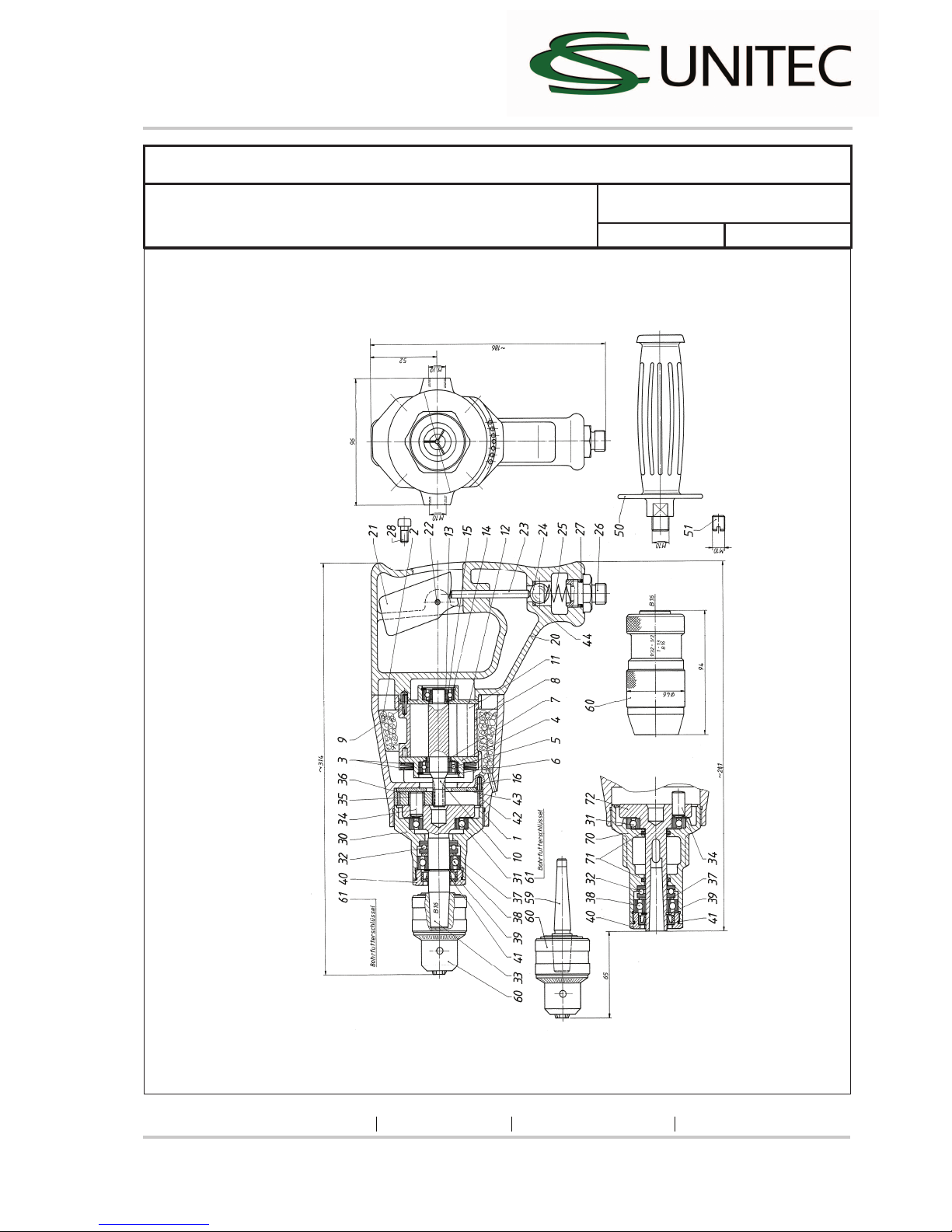
DEMONTAGE UND MONTAGE
Disassembly
Disassembly and reassembly should only be performed with the assistance of the sectional
drawing.
All parts can be dismantled by light pushing or knocking (wooden base / rubber hammer).
Motor
Loosen screws (item 28), remove handle (item 20), pull out inner motor parts and dismantle. Check
wear parts - especially the vanes (item 11).
Valve
Screw out nipple (item 26) and take out valve parts. Replace worn parts if necessary.
Gearbox
Screw neck (item30 or item 70) out of motor housing. (Attention! Left-hand thread). Remove rim of
the gear (item 42) and washer (item 43). Draw off drill chuck (item 60). Loosen cover lid (item 40),
remove snap ring (item 39) and press out complete planet carrier (item 33 or item 72). Check
wear parts as radial shaft seals (item 41) and ball bearings and replace if necessary.
Assembly hints
Repairs should be executed by authorized professionals only and with assistance of the sectional
drawing.
ne_010011312_02_010001312 80.30.52 :delipmoC
CS Unitec, Inc 22 Harbor Ave USANorwalk, CT 06850
Phone: (203) 853 9522 Fax: (203) 853 9921 info@csunitec.com
Page 7 of 20
Page 8

Pneumatic
Drill
2 1310 0010-0020, 2 1311 0010
Reassembly
Perform reassembly after checking and replacing worn parts. It will be done basically in the reverse
order than the disassembly. Lightly grease all parts to avoid falling apart during reassembly.
Remove any oil and resin residue from the rotor slots. The vanes should fit easily into the rotor
slots.
Motor running
If the motor cannot be turned after reassembly, light axial or lateral tapping with a rubber hammer
on motor housing is helpful. The rotor places and comes into free-wheel position between the end
plates. If not, check length of the rotor, cylinder bushing and vanes.
a. The vanes must not jut out laterally of the rotor slots and not project on the rotor.
b. Cylinder bushing has to be 0.08 mm to 0.10 mm longer than the rotor.
Check all functions after finishing the reassembly, especially free speed and air consumption
according to "Technical Specifications".
Use only original Spitznas Spare Parts for repairs!
Cylinder bushin
g
clearance
clearanc
Vane shorter than rotor
Shorter than cylinder Rotor
ne_010011312_02_010001312 80.30.52 :delipmoC
CS Unitec, Inc 22 Harbor Ave USANorwalk, CT 06850
Phone: (203) 853 9522 Fax: (203) 853 9921 info@csunitec.com
Page 8 of 20
Page 9

Pneumatic
Drill
2 1310 0010-0020, 2 1311 0010
ne_010011312_02_010001312 80.30.52 :delipmoC
CS Unitec, Inc 22 Harbor Ave USANorwalk, CT 06850
Phone: (203) 853 9522 Fax: (203) 853 9921 info@csunitec.com
Page 9 of 20
Trouble/ Probable Cause/ Remedy
Remedy
Connect and open air line Disassemble and clean motor, check and test
service unit for function
Disassemble motor, clean and replace worn
parts
Disassemble and clean gearbox and replace
worn parts
clean s
eat
Increase operating pressure to 6 bar (on the
machine)
Disassemble and clean motor, replace worn
parts
Disassemble and clean gearbox, replace worn
parts
Dissassemble and clean motor, replace worn
parts
Disassemble and clean motor, replace worn
parts
Disassemble and clean motor, replace worn
parts
Disassemble and clean gearbox, replace worn
parts
Change drill chuck use bigger tool
Clean machine Disassemble gearbox and replace defective
parts
Probable cause
Air not connected Rotor rusted by humid
Vanes jam (worn)
Gearbox blocks
Contaminates in valve
Operating pressure too low Rotor grinds on end plates / cylinder bushing
Gear parts jam Vanes worn or broken, broken parts stick between rotor
and cylinder bushing
No lubrication - ball bearings have run dry, rotor has
rubbed on end plates
Coarse impurities in motor area jam between rotor and
cylinder bushing
Toothing is clattering Ball bearings defective
Drill chuck defective Diameter of tool too small
Dirt in reversing area Steel rollers clamp
Trouble
Machine does not start
Trigger clamps Machine rotates too slowly
Motor sticks / jams
Gearbox makes loud noises
Tool not able to be clamped
Reversing „drilling / hammering “ clamps
Page 10

Pneumatic
Drill
2 1310 0010-0020, 2 1311 0010
Spare Parts List
Description: Part and drawing number
Pneumatic
Drill
2 1310 0010
Page no.: 1/3 Date: 03/08
Item skrameR .on gniward dna traP noitpircseD .ytQ
1 1
Motor housing
2 1311 1010
2 2
Damping material
1 2034 6100
3 2
Belleville spring
9 1802 0260
4 1
End plate
7 1401 1100
5 1
Grooved ball bearing
9 1003 0030
6 1
Snap ring
9 1703 0100
7 1
Spacer
1 1501 1090
8 1
Cylinder bushing
1 1379 1020
9 1
Adapter sleeve
9 1630 0510
10 1
Rotor
2 1311 1030
11 6
Vane
2 1310 1050
12 1
End plate
2 1310 1110
13 1
Grooved ball bearing
9 1003 0010
14 1
Snap ring
9 1703 0050
15 1
Spacer
2 1301 1090
16 2
Adapter sleeve
9 1630 0140
20 1
Handle
2 1310 6010
21 1
Valve pusher
2 1311 3040
22 1
Double notched pin
9 1641 0020
23 1
Cylindrical pin
9 1619 1360
24 1
Ball
9 1017 0080
25 1
Compression spring
9 1803 0250
26 1
Nipple
9 2205 1190
27 1
O-Ring
9 1901 3230
28 4
Fillister-head screw
9 1110 4010
30 1
Neck
2 1301 7010
31 1
Grooved ball bearing
9 1002 0040
32 1
Journal bearing
9 1021 0040
33 1
Planet carrier
2 1310 4910 With item 34
34 3
Cylindrical pin
9 1631 0170
35 3
Needle cage
9 1015 0110
36 3
Planetary wheel
2 1301 4040
37 2
Fitting washer
9 3331 0230
ne_010011312_02_010001312 80.30.52 :delipmoC
CS Unitec, Inc 22 Harbor Ave USANorwalk, CT 06850
Phone: (203) 853 9522 Fax: (203) 853 9921 info@csunitec.com
Page 10 of 20
Page 11

Pneumatic
Drill
2 1310 0010-0020, 2 1311 0010
Spare Parts List
Description: Part and drawing number:
Pneumatic
Drill
2 1310 0010
Page no.: 2/3 Date: 03/08
Item skrameR .on gniward dna traP noitpircseD .ytQ
38 1
Grooved ball bearing
9 1003 0040
39 1
Snap ring
9 1702 0100
40 1
Cover lid
2 1311 4100
41 1
Radial shaft seal
9 1905 0020
42 1
Rim of the gear
2 1301 4020
43 1
Washer
2 1311 4080
50 1
Handle
2 1312 6010
60 1
Drill chuck
9 2901 0120
61 1
Spanner for drill chuck
9 1419 0030
44 1
Seal
9 1903 0160
51 1
Hexagon screw
9 1107 6140
ne_010011312_02_010001312 80.30.52 :delipmoC
CS Unitec, Inc 22 Harbor Ave USANorwalk, CT 06850
Phone: (203) 853 9522 Fax: (203) 853 9921 info@csunitec.com
Page 11 of 20
Page 12
Pneumatic
Drill
2 1310 0010-0020, 2 1311 0010
Spare Parts List
Description: Part and drawing number:
Pneumatic
Drill
2 1310 0010
Page no.: 3/3 Date: 03/08
ne_010011312_02_010001312 80.30.52 :delipmoC
CS Unitec, Inc 22 Harbor Ave USANorwalk, CT 06850
Phone: (203) 853 9522 Fax: (203) 853 9921 info@csunitec.com
Page 12 of 20
Page 13

Pneumatic
Drill
2 1310 0010-0020, 2 1311 0010
Spare Parts List
Description: Part and drawing number
Pneumatic
Drill
2 1310 0020
Page no.: 1/3 Date: 03/08
Item skrameR .on gniward dna traP noitpircseD .ytQ
1 1
Motor housing
2 1311 1010
2 2
Damping material
1 2034 6100
3 2
Belleville spring
9 1802 0260
4 1
End plate
7 1401 1100
5 1
Grooved ball bearing
9 1003 0030
6 1
Snap ring
9 1703 0100
7 1
Spacer
1 1501 1090
8 1
Cylinder bushing
1 1379 1020
9 1
Adapter sleeve
9 1630 0510
10 1
Rotor
2 1311 1030
11 6
Vane
2 1310 1050
12 1
End plate
2 1310 1110
13 1
Grooved ball bearing
9 1003 0010
14 1
Snap ring
9 1703 0050
15 1
Spacer
2 1301 1090
16 2
Adapter sleeve
9 1630 0140
20 1
Handle
2 1310 6010
21 1
Valve pusher
2 1311 3040
22 1
Double notched pin
9 1641 0020
23 1
Cylindrical pin
9 1619 1360
24 1
Ball
9 1017 0080
25 1
Compression spring
9 1803 0250
26 1
Nipple
9 2205 1190
27 1
O-Ring
9 1901 3230
28 4
Fillister-head screw
9 1110 4010
30 1
Neck
2 1301 7010
31 1
Grooved ball bearing
9 1002 0040
32 1
Journal bearing
9 1021 0040
33 1
Planet carrier
2 1310 4910 With item 34
34 3
Cylindrical pin
9 1631 0170
35 3
Needle cage
9 1015 0110
36 3
Planetary wheel
2 1301 4040
37 2
Fitting washer
9 3331 0230
ne_010011312_02_010001312 80.30.52 :delipmoC
CS Unitec, Inc 22 Harbor Ave USANorwalk, CT 06850
Phone: (203) 853 9522 Fax: (203) 853 9921 info@csunitec.com
Page 13 of 20
Page 14

Pneumatic
Drill
2 1310 0010-0020, 2 1311 0010
Spare Parts List
Description: Part and drawing number:
Pneumatic
Drill
2 1310 0020
Page no.: 2/3 Date: 03/08
Item skrameR .on gniward dna traP noitpircseD .ytQ
38 1
Grooved ball bearing
9 1003 0040
39 1
Snap ring
9 1702 0100
40 1
Cover lid
2 1311 4100
41 1
Radial shaft seal
9 1905 0020
42 1
Rim of the gear
2 1301 4020
43 1
Washer
2 1311 4080
50 1
Handle
2 1312 6010
60 1
Quick release drill chuck
9 2902 0040
44 1
Seal
9 1903 0160
51 1
Hexagon screw
9 1107 6140
ne_010011312_02_010001312 80.30.52 :delipmoC
CS Unitec, Inc 22 Harbor Ave USANorwalk, CT 06850
Phone: (203) 853 9522 Fax: (203) 853 9921 info@csunitec.com
Page 14 of 20
Page 15

Pneumatic
Drill
2 1310 0010-0020, 2 1311 0010
Spare Parts List
Description: Part and drawing number:
Pneumatic
Drill
2 1310 0020
Page no.: 3/3 Date: 03/08
ne_010011312_02_010001312 80.30.52 :delipmoC
CS Unitec, Inc 22 Harbor Ave USANorwalk, CT 06850
Phone: (203) 853 9522 Fax: (203) 853 9921 info@csunitec.com
Page 15 of 20
Page 16

Pneumatic
Drill
2 1310 0010-0020, 2 1311 0010
Spare Parts List
Description: Part and drawing number
Pneumatic
Drill
2 1311 0010
Page no.: 1/3 Date: 03/08
Item skrameR .on gniward dna traP noitpircseD .ytQ
1 1 Motor housing 2 1311 1010
2 2 Damping material 1 2034 6100
3 2 Belleville spring 9 1802 0260
4 1 End plate 7 1401 1100
5 1 Grooved ball bearing 9 1003 0030
6 1 Snap ring 9 1703 0100
7 1 Spacer 1 1501 1090
8 1 Cylinder bushing 1 1379 1020
9 1 Adapter sleeve 9 1630 0510
10 1 Rotor 2 1311 1030
11 6 Vane 2 1310 1050
12 1 End plate 2 1310 1110
13 1 Grooved ball bearing 9 1003 0010
14 1 Snap ring 9 1703 0050
15 1 Spacer 2 1301 1090
16 2 Adapter sleeve 9 1630 0140
20 1 Handle 2 1310 6010
21 1 Valve pusher 2 1311 3040
22 1 Double notched pin 9 1641 0020
23 1 Cylindrical pin 9 1619 1360
24 1 Ball 9 1017 0080
25 1 Compression spring 9 1803 0250
26 1 Nipple 9 2205 1190
27 1 O-Ring 9 1901 3230
28 4 Fillister-head screw 9 1110 4010
70 1 Neck, Assy. 2 1302 7910
71 2 Felt ring 9 1902 0090
31 1 Grooved ball bearing 9 1002 0040
32 1 Journal bearing 9 1021 0040 With item 34
72 1 Planet carrier 2 1311 4910
0710 1361 9 denedrah ,nip lacirdnilyC 3 43
35 3 Needle cage 9 1015 0110
36 3 Planetary wheel 2 1301 4040
ne_010011312_02_010001312 80.30.52 :delipmoC
CS Unitec, Inc 22 Harbor Ave USANorwalk, CT 06850
Phone: (203) 853 9522 Fax: (203) 853 9921 info@csunitec.com
Page 16 of 20
Page 17

Pneumatic
Drill
2 1310 0010-0020, 2 1311 0010
Spare Parts List
Description: Part and drawing number:
Pneumatic
Drill
2 1311 0010
Page no.: 2/3 Date: 03/08
Item skrameR .on gniward dna traP noitpircseD .ytQ
37 2 Fitting washer 9 3331 0230
38 1 Grooved ball bearing 9 1003 0040
39 1 Snap ring 9 1702 0100
40 1 Cover lid 2 1311 4100
41 1 Radial shaft seal 9 1905 0020
42 1 Rim of the gear 2 1301 4020
43 1 Washer 2 1311 4080
50 1 Handle 2 1312 6010
44 1 Seal 9 1903 0160
ne_010011312_02_010001312 80.30.52 :delipmoC
CS Unitec, Inc 22 Harbor Ave USANorwalk, CT 06850
Phone: (203) 853 9522 Fax: (203) 853 9921 info@csunitec.com
Page 17 of 20
Page 18

Pneumatic
Drill
2 1310 0010-0020, 2 1311 0010
Spare Parts List
Description: Part and drawing number:
Pneumatic
Drill
2 1311 0010
Page no.: 3/3 Date: 03/08
ne_010011312_02_010001312 80.30.52 :delipmoC
CS Unitec, Inc 22 Harbor Ave USANorwalk, CT 06850
Phone: (203) 853 9522 Fax: (203) 853 9921 info@csunitec.com
Page 18 of 20
Page 19

Pneumatic
Drill
2 1310 0010-0020, 2 1311 0010
ne_010011312_02_010001312 80.30.52 :delipmoC
CS Unitec, Inc 22 Harbor Ave USANorwalk, CT 06850
Phone: (203) 853 9522 Fax: (203) 853 9921 info@csunitec.com
Page 19 of 20
Page 20

Pneumatic
Drill
2 1310 0010-0020, 2 1311 0010
ne_010011312_02_010001312 80.30.52 :delipmoC
CS Unitec, Inc 22 Harbor Ave USANorwalk, CT 06850
Phone: (203) 853 9522 Fax: (203) 853 9921 info@csunitec.com
Page 20 of 20
 Loading...