

Page 1
10 320
Hergestellt für:
Inter-Union Technohandel GmbH
Klaus-von-Klitzing-Str. 2
76829 Landau · Germany
www.inter-union.de
Stand: 10/2009
Version: 1.0
Modell: 07495
D
Auffahrrampe Alu
Loading ramp, aluminium
F Rampe de chargement en alu
I Rampa di carico in alluminio
Aluminiowa rampa najazdowa
Gebrauchsanweisung
𐀕
22
PAP
Instructions for use
Mode d’emploi
Istruzioni per l’uso
Instrukcja
Instrukcja
Należy koniecznie przestrzegać poniższych zaleceń!
• Jeżeli rozstaw osi jest mniejszy niż podany na schemacie 1 minimalny rozstaw osi,
rampy nie mogą udźwignąć maksymalnego obciążenia całkowitego!
• Stosować tylko w parze i ustawiać równolegle!
• Podłoże musi być twarde i płaskie!
• Wjeżdżać na rampę zawsze pod nadzorem drugiej osoby!
• Pod szyną załadowczą nie mogą przebywać ludzie!
Zabronione jest używanie rampy w pozycji poziomej. Nie wolno używać rampy jako
pomostu przeładunkowego.
Rampy należy zamocować tak, aby podczas wjeżdżania na nie, nie przemieszczały
się z ustawionego położenia. Można je zamocować do podłoża przyczepy dwoma
trzpieniami na rampę.
Rampy należy używać z zachowaniem rozwagi!
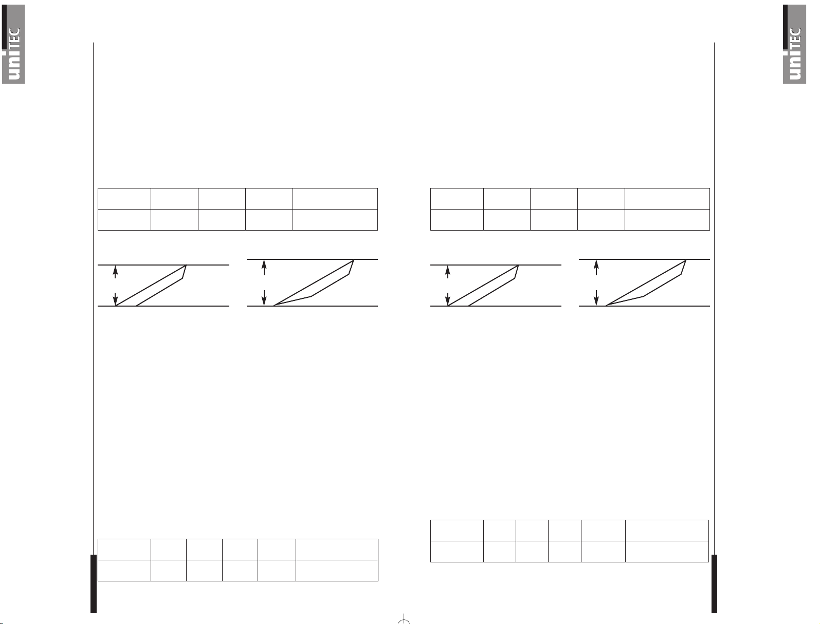
Wysokość najazdu, schemat 1
Obciążenie całkowite = ciężar całkowity pojazdu wraz z paliwem + ciężar kierowcy
+ ewentualne urządzenia
Obliczenia zostały wykonane dla pojazdu dwuosiowego, przy czym 1/3 ciężaru
została przypisana jednej osi a 2/3 drugiej osi. Obciążenie całkowite na środku rampy
odpowiada 1/3 maksymalnego obciążenia całkowitego (patrz schemat 2).
W przypadku przekroczenia podanego maksymalnego obciążenia całkowitego,
istnieje niebezpieczeństwo, że rampy się złamią. Gwarancja ani ubezpieczenie od
odpowiedzialności za produkt nie obejmują szkód spowodowanych przekroczeniem
obciążenia całkowitego.
Podane każdorazowo obciążenie dopuszczalne odnosi się zastosowania kół
gumowych o powierzchni nacisku wynoszącej 100 x 150 (100 mm w kierunku jazdy i
150 mm 90° do kierunku jazdy). Przy mniejszej powierzchni nacisku kół obciążalność
ramp najazdowych zmniejsza się. Nie wolno najeżdżać na rampę pojazdami
gąsienicowymi, ponieważ gąsienice mogą w przypadku zmiany kierunku jazdy
uszkodzić materiał, z którego wykonana jest rampa.
Zwiększenie prędkości zwiększa obciążenie (wpływ dynamiczny). Dane dot. obciążenia dopuszczalnego odnoszą się do stałej prędkości. Prędkość należy ograniczyć do
tempa poruszania się pieszego. Należy unikać szybkiego najeżdżania i hamowania,
ponieważ w wyniku tego mogłoby dojść do rozedrgania się ramp, a przez to do ich
większego obciążenia (25% - 50%).
Obciążenie dopuszczalne aluminiowej rampy najazdowej, schemat 2
Ostrzeżenie! Nie udzielamy gwarancji w przypadku nieprawidłowego zastosowania
ramp.
Wskazówki
dotyczące
bezpieczeństwa
Reklamacja
Powierzchnia
nacisku koła
Prędkość
Tekst Długość
Min.
wysokość
Maks.
wysokość
Min. rozstaw osi
Rampa, prosta 1,5 m 400 mm 500 mm 750 mm
Tekst Szerokość Wysokość Długość
Min. szero-
kość kół
Maks. obciążenie całko-
wite na metr rampy
Rampa, prosta 215 mm 34 mm 1500 mm 195 mm 400 kg
Min. wysokość najazdu
Obliczenie obciążenia całkowitego
Maks. rozstaw osi
Min. wysoko-
ść najazdu
Maks. wysokość najazdu
Page 2
Gebrauchsanweisung
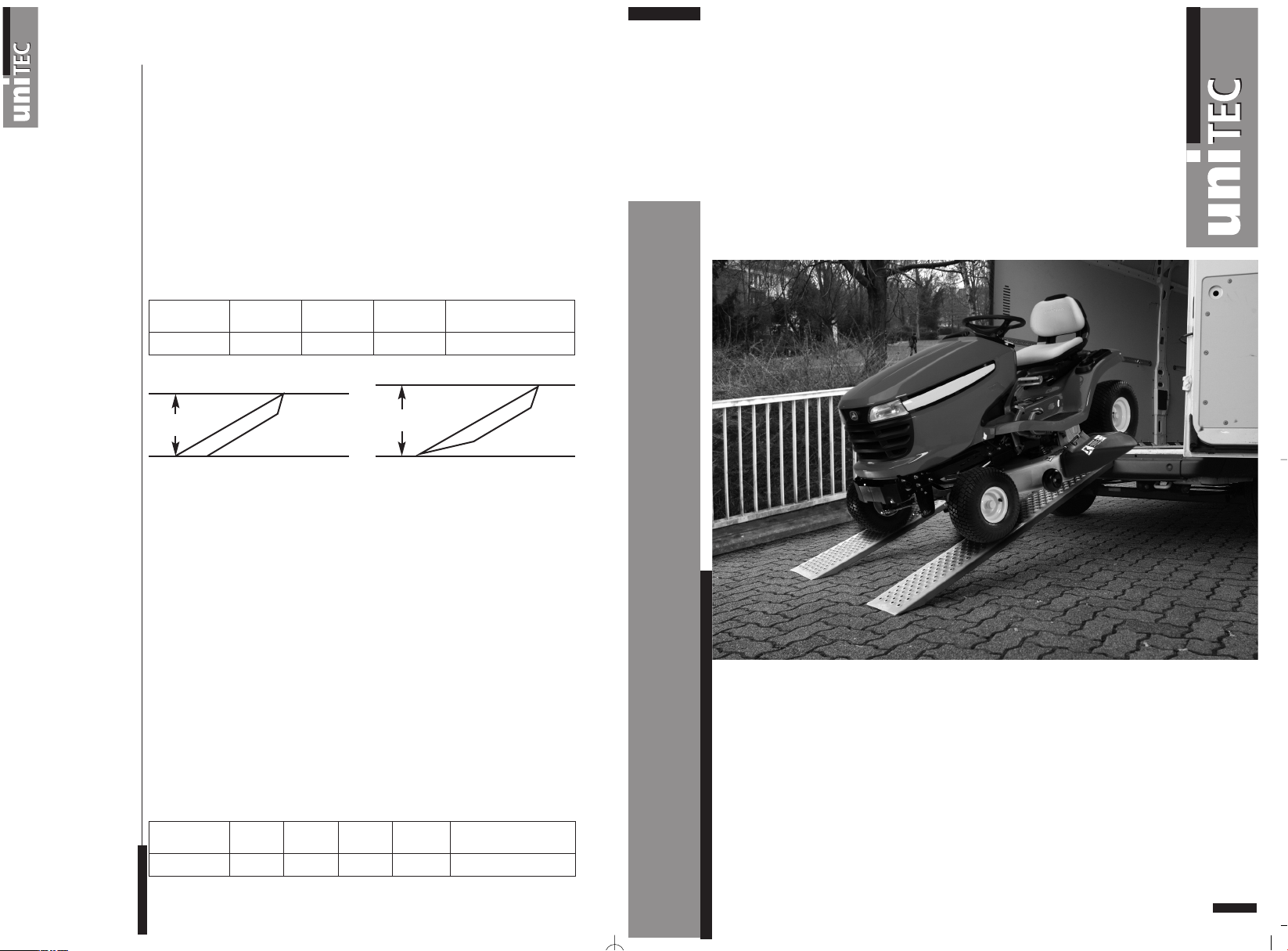
Bitte unbedingt beachten!
• Wenn der Achsenabstand kleiner als der im Schema 1 angegebene
Minimumachsenabstand ist, können die Rampen die max. Totallast nicht tragen!
• Nur Paarweise verwenden und parallel aufstellen!
• Auf festen, ebenen Untergrund achten!
• Auffahren nur unter Aufsicht einer zweiten Person!
• Es dürfen sich keine Personen unterhalb der Ladeschiene befinden!
Waagerechter Gebrauch der Rampe ist nicht gestattet. Die Rampen dürfen nicht als
Ladebrücke verwendet werden.
Die Rampen müssen befestigt werden, so dass sie beim Befahren nicht ausscheren.
Sie können mit 2 Bolzen pro Rampe im Boden des Anhängers befestigt werden.
Die Rampe soll mit Umsicht benutzt werden!
Auffahrhöhe, Schema 1
Totalbelastung = Totalgewicht des Fahrzeugs inkl. Brennstoff + Gewicht d. Fahrers +
evtl. Geräte
Die Berechnungen sind mit einem 2-Achsen-Fahrzeug durchgeführt worden, wobei
das Gewicht mit 1/3 auf die eine Achse und mit 2/3 auf die andere Achse verteilt wurde. Die Totalbelastung in der Mitte einer Rampe entspricht 1/3 der max. Totalbelastung (siehe Schema 2).
Wenn die max. angegebene Totalbelastung überschritten wird, besteht die Gefahr,
dass die Rampen brechen. Schäden durch Überschreiten der Totalbelastung sind
nicht in der Garantie oder der Produkthaftungsversicherung umfasst.
Die jeweils angegebene Tragfähigkeit basiert auf einer Verwendung von Gummirädern mit einer min. Rad-Druck-Fläche von 100x150 (100 mm in Fahrrichtung und
150 mm 90° in der Fahrrichtung). Bei weniger Rad-Druck-Fläche wird die Belastbarkeit der Auffahrrampen verringert. Ein Kettenfahrzeug darf nicht verwendet werden,
weil die Ketten bei einer Änderung der Fahrrichtung das Material beschädigen.
Die Belastung wird durch die Geschwindigkeit erhöht (dynamische Beeinflussung).
Die Tragfähigkeit basiert auf einer gleichmäßigen Geschwindigkeit. Die Geschwindigkeit muss auf Schrittgeschwindigkeit begrenzt werden. Schnelles Auffahren und
Abbremsen muss vermieden werden, da dadurch die Rampen in Schwingungen, mit
wesentlichen Mehrbelastungen (25%-50%), gebracht werden.
Tragfähigkeit für Aluminiumauffahrrampe, Schema 2
Warnung! Wir leisten keine Garantie, falls die Rampen falsch angewendet werden.
Sicherheits-
hinweise
Reklamation
Rad-Druck-Fläche
Geschwindigkeit
Ensure that these procedures are followed!
• If the axle clearance is smaller than the minimum distance shown in fig. 1,
the ramps may not be able to bear the maximum total load.
• Use only in pairs placed in parallel alignment.
• Always place on a firm and even surface.
• Load only with the assistance of a second person.
• DO NOT remain or pass under the ramps while loading is taking place.
The ramps must not be used in a horizontal position. The ramps must not be
used as a loading bridge.
The ramps must be secured to prevent them slipping out of place during use.
They should be fixed to the trailer using two bolts screwed into each ramp.
Proceed with great care when using the ramps.
Loading height, fig. 1
Total load = total weight of vehicle (incl. fuel) + weight of driver + any object carried
These calculations were carried out with a two-axle vehicle, with one third of the
weight distributed to one axle and two thirds to the other. The total load at the centre
of each ramp corresponds to one third of the maximum total load (see fig. 2).
If the indicated maximum total load is exceeded, there is a danger of the ramps
breaking. Loss or damage caused by exceeding the total load is not covered by the
warranty or product-liability insurance.
The loading capacity indicated is based on the use of rubber tyres with a minimum
wheel-contact surface of 100x150 (100 mm in direction of travel and 150 mm 90° in
direction of travel). The use of a lower wheel-contact surface will reduce the
weight-bearing capacity of the loading ramps. Not suitable for use with tracked
vehicles, as the steering system used is likely to cause damage.
The load capacity increases with speed (dynamic factor). The load capacity is based
on a constant speed. Loading speed must be limited to creep-velocity. Avoid brusque
acceleration and braking, as these are likely to subject the ramps to oscillations that
can amount to an additional load factor of between 25% and 50%.
Weight-bearing capacity of aluminium loading ramps, fig. 2
Warning! Incorrect use of the ramps will void the warranty.
Safety
precautions
Possible claims
Wheel contact surface
Speed
D
Text Länge Min. Höhe Max. Höhe Min. Achsenabstand
Rampe, gerade 1,5 m 400 mm 500 mm 750 mm
Text Breite Höhe Länge
Min.
Radbreite
Max. Totalbelastung
pro Rampenmeter
Rampe, gerade 215 mm 34 mm 1500 mm 195 mm 400 kg
Min. Auffahrhöhe
Berechnung der Totalbelastung
Max. Achsenabstand
Min.
Auffahrhöhe
Max.
Auffahrhöhe
Instructions for use
Text Length Min. height Max. height Min. axle clearance
Ramp, straight 1,5 m 400 mm 500 mm 750 mm
Text Width Height Length
Min. wheel
width
Max. total load per
metre-length of ramp
Ramp, straight 215 mm 34 mm 1500 mm 195 mm 400 kg
Min. loading height
Calculating the total load
Max. axle clearance
Min. loading
height
Max. loading
height
Page 3

Mode d'emploi
A respecter impérativement!
• Si l’empattement est inférieur à l’empattement minimum indiqué au schéma 1,
les rampes ne peuvent alors pas supporter la charge totale max.!
• Utiliser uniquement par paire et monter en parallèle!
• Veiller à disposer d’un fond solide et plat!
• Effectuer la montée uniquement sous la surveillance d’une seconde personne!
• Aucune personne ne doit se trouver sous le rail de chargement!
L’utilisation horizontale de la rampe est interdite. Les rampes ne doivent pas être utilisées comme passerelle de charge.
Les rampes doivent être fixées pour ne pas déboîter pendant le passage des véhicules. Elles peuvent être fixées sur le fond de la remorque par 2 boulons par rampe.
La rampe doit être utilisée avec prudence!
Hauteur de chargement, schéma 1
Charge totale = Poids total du véhicule, carburant + poids du conducteur + appareils
éventuels inclus
Les calculs ont été effectués avec un véhicule à 2 essieux, en l’occurrence de quoi
la répartition du poids était de 1/3 sur un essieu et de 2/3 sur l‘autre. La charge totale
au centre d’une rampe correspond à 1/3 de la charge totale max. (voir schéma 2).
Si la charge totale max. indiquée est dépassée, il existe un risque de cassure des
rampes. La garantie et l’assurance responsabilité produit ne couvrent pas les dommages résultant du dépassement de la charge totale.
Les différentes charges admissibles indiquées se basent sur l’utilisation de roues
caoutchoutées avec une surface d‘appui min. de 100x150 (100 mm dans le sens de la
marche et 150 mm 90° dans le sens de la marche). La charge des rampes de chargement est réduite en cas de surface d’appui moindre. Un véhicule chenillé ne doit pas
être utilisé, car les chaînes endommagent le matériel en cas de changement de
direction.
La vitesse augmente la sollicitation (influence dynamique). La charge admissible est
basée sur une vitesse régulière. La vitesse doit être réduite à une vitesse au pas.
Eviter la montée rapide et le freinage, car cela provoque des vibrations qui causent
de fortes sollicitations supplémentaires (25% - 50%).
Charge admissible rampe en aluminium, schéma 2
Avertissement! Nous n’assumons aucune garantie en cas d’usage non conforme
des rampes.
Consignes de
sécurité
Réclamation
Surface d‘appui
des roues
Vitesse
Si raccomanda di osservare le seguenti indicazioni!
• Se l’interasse è inferiore all’interasse minimo riportato allo schema 1,
le rampe non sono in grado di sostenere il carico totale max.!
• Utilizzarle solo a coppie e collocarle parallelamente!
• Collocarle su un fondo solido e piano!
• Salire solo sotto la supervisione di un’altra persona!
• Non devono essere presenti persone sotto le guide di carico!
Non è ammesso un utilizzo orizzontale della rampa. Non utilizzare le rampe come
passerelle di carico.
Fissare le rampe per fare in modo che non si spostino mentre si attraversano.
Si possono fissare con 2 bulloni per rampa nel fondo del rimorchio.
Utilizzare la rampa con prudenza!
Altezza di salita, schema 1
Carico totale = peso totale del veicolo incl. carburante + peso conducente + ev.
dispositivi
I calcoli sono stati eseguiti con un veicolo a 2 assi nel quale il peso è stato ripartito
per 1/3 su un asse e per 2/3 sull’altro asse. Il carico totale al centro di una rampa
corrisponde a 1/3 del carico totale max. (vedere schema 2).
Se si supera il carico totale max. indicato, sussiste il pericolo di rottura delle rampe.
I danni causati dal superamento del carico totale non sono inclusi nella garanzia o
nell’assicurazione di responsabilità civile del prodotto.
Il carico limite indicato si basa sull’impiego di ruote in gomma con un’impronta di
contatto min. di 100x150 (100 mm in direzione di marcia e 150 mm a 90° in direzione
di marcia). Con un’impronta di contatto inferiore, si riduce la capacità di carico della
rampa di salita. Non utilizzare un mezzo cingolato, in caso contrario i cingoli possono
danneggiare il materiale se si modifica la direzione di marcia.
Il carico aumenta con la velocità (influsso dinamico). Il carico limite si basa su una
velocità uniforme. Limitare la velocità alla velocità a passo d’uomo. Evitare di salire
rapidamente e frenare per non far oscillare le rampe, causando sovraccarichi
(25%-50%).
Carico limite per la rampa di salita in alluminio, schema 2
Attenzione! La garanzia decade in caso di utilizzo errato della rampa.
Indicazioni di
sicurezza
Reclamo
Impronta di contatto
Velocità
F
Istruzioni per l’uso
I
Text Longueur Hauteur min. Hauteur max. Empattement min.
Rampe, droite 1,5 m 400 mm 500 mm 750 mm
Texte Largeur Hauteur Longueur
Empatteme
nt min.
Charge totale max.
par mètre de rampe
Rampe, droite 215 mm 34 mm 1500 mm 195 mm 400 kg
Hauteur d’accès min.
Calcul de la charge totale
Empattement max.
Hauteur
d’accès min.
Hauteur
d’accès max.
Testo Lunghezza Altezza min. Altezza max. Interasse min.
Rampa, dritta 1,5 m 400 mm 500 mm 750 mm
Testo
Larg-
hezza
Altezza
Lunghezza
Larghezza
ruota min.
Carico totale max.
Per metro di rampa
Rampa, dritta 215 mm 34 mm 1500 mm 195 mm 400 kg
Altezza di salita min.
Calcolo del carico totale
Interasse max.
Altezza di
salita min.
Altezza di
salita max.
 Loading...