

Page 1
CA.TALOG NO.
KA.TALOG
234
NR.
Instructions and
illustrated parts list
Betriebsanleitung und
illustriertes Teileverzeichnis
STYLES
TYPEN
81500 A
81500
81500
81500
81500
8
BA
c
E
I
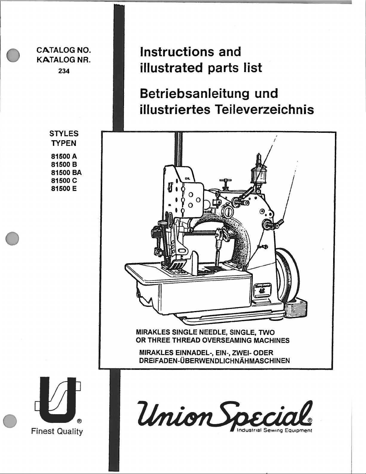
MIRAKLES SINGLE NEEDLE, SINGLE,
OR THREE THREAD OVERSEAMING MACHINES
®
MIRAKLES
DREIFADEN-0BERWENDLICHNAHMASCHINEN
EINNADEL-,
EIN
Finest Quality
-, ZWEI-
TWO
ODER
Page 2

•
Page 3
TABLE OF CONTENTS
INHALTSVERZEICHNIS
SAFETY RULES
SICHERHEITSHINWEISE
IDENTIFICATION OF MACHINES
BEZEICHNUNG
APPLICATION OF THIS INSTRUCTION
HINWEIS ZUR BENOTZUNG DIESER BETRIEBSANLEITUNG
STYLES OF MACHINES
MASCHINENTPYEN
DER MASCHINEN
MANUAL
PAGE
SEITE
1-2
2
2
3-4
INSTALLATION, LUBRICATION, NEEDLES
AUFSTELLUNG,OLEN,NADELN
OPERATING INSTRUCTIONS
BEDIENUNGSANLEITUNG
MAINTENANCE
WARTUNG
INSTRUCTIONS FOR MECHANICS
MECHANIKERANLEITUNG
ORDERING REPAIR PARTS
BESTELLUNG VON ERSATZTEILEN
EXPLODED VIEWS
EXPLOSIONSZEICHNUNGEN
BUSHINGS, SIGHT
BUCHSEN,TROPFOLER,OLER
CLOTH PLATE, BASE PLATE, GUARDS AND MISCELLANEOUS COVERS
STOFFPLATTE,
THREAD
FADENSPANNUNGS- UNO FADENFOHRUNGSTEILE
NEEDLE BAR, NEEDLE LEVER, CRANKSHAFT, HANDWHEEL-PULLEY
NADELSTANGE, NADELHEBEL, KURBELWELLE,
LOOPER DRIVE MECHANISM
GREIFERANTRIEBS-MECHANISMUS
UPPER AND
OBER- UNO UNTERTRANSPORT-ANTRIEBSMECHANISMUS
PRESSER BARS, PRESSER
DROCKERFUSS-STANGEN, FEDERN
DROCKERFUSS-LIFTERHEBEL
SEWING PARTS, STYLES 81500A, 81500
NAHTEILE, MASCHINEN 81500
SEWING PARTS, STYLE 81500
NAHTEILE, MASCHINE 81500 E
ACCESSORIES
ZUBEHOR
NUMERICAL INDEX
AUF WELCHER SEITE FINDE ICH TEILE
TENSION
AND
DESCRIPTION OF PARTS
UNO
BESCHREIBUNG DER TEILE
FEED
OILER, OILERS
GRUNDPLATTE, SCHUTZTEILE UNO VERSCH. ABDECKUNGEN
AND
THREAD GUIDE PARTS
HANDRAD-RIEMENSCHEIBE
LOWER
FEED DRIVE MECHANISM
BAR SPRINGS AND PRESSER FOOT LIFTER LEVER
FOR
OROCKERFUSS-STANGEN UNO
B,
A,
81500
B,
E
OF
PARTS
UNO
81500
BAAND
81500
BA
IHRE ABBILDUNGEN
81500 C
UNO 81500 C
5-10
10-14
15
16-26
27
28-50
29-30
31-32
33-36
37-38
39-40
41
-42
43-44
45-46
47-48
49-50
51-52
Page 4
INSTRUCTIONS AND ILLUS, AATED PARTS LIST NO.
BETRIEBSANLEITUNG
UNO
ILLUSTRIERTES TEILEVERZEICHNIS NR.
For
Styles
FOr
die
Typen
234
CATALOG
81500 A
81500 B
PREFACE
This instruction manual is designed to
with the machine/ unit and its designated
The instruction manual contains important information
how to operate the machine/ unit safely, properly
efficiently. Observing these instructions helps to avoid
ger, to reduce repair costs and downtimes
the reliability and life
The instruction manual is
spective national rules and regulations for accident preven-
tion and environmental protection.
The instruction manual must always
the machine/ unit is in use.
This instruction manual
person in charge of carrying out work
machine/ unit, such as
- operation including setting
course
of
work and care.
maintenance (servicing, inspection, repair) and/ or
transport.
-
In addition to the operating instructions
tory rules and regulations for accident prevention and
vironmental protection in the country and place
the machine/ unit, the generally recognized technical rules
for safe and proper working
of
the machine/ unit.
to
be supplemented
must
be
up,
must
familiarize the user
use.
and
and
to increase
by
be
available wherever
read
and applied
with
and
troubleshooting in the
and
to the manda-
of
also
be
observed.
on
most
dan-
the re-
by
any
on
the
en-
use
of
81500
BA
81500 c
81500 E
VORWORT
Diese Betriebsanleitung soli erleichtern, die Maschine/ Anlage
kennenzulemen und ihre bestimmungsgemaBen Einsatzmoglichkeiten zu nutzen.
Die Betriebsanleitung
Anlage sicher, sachgerecht und wirtschaftlich zu betreiben.
re Beachtung hilft, Gefahren zu vermeiden, Reparaturkosten
und Ausfallzeiten
die Lebensdauer der Maschine/ Anlage zu
Die Betriebsanleitung ist urn Anweisungen aufgrund bestehender nationaler Vorschriften zur Unfallverhotung
Umweltschutz
Die Betriebsanleitung muB standig am Einsatzort der Maschine/ Anlage
Die Betriebsanleitung ist von jeder Person zu lesen und
anzuwenden, die mit Arbeiten
verfOgbar sein.
enthalt wichtige Hinweise, die Maschine/
zu
vermindem und ·die Zuverlassigkeit und
zu
erganzen.
mit/
erhOhen.
an der Maschine/ Anlage
und
z. 8.
Bedienung, einschlieBiich
im Arbeitsablauf und Pflege.
lnstandhaltung (Wartung, lnspektion, lnstandsetzung)
undl oder
Transport
beauftragt ist.
Neben der Betriebsanleitung und den
an
der Einsatzstelle geltenden verbindlichen Regelungen zur
Unfallverhotung sind auch die anerkannten fachtechnischen
Regeln tar sicherheits- und -fachgerechtes Arbeiten
ten.
ROsten,
Storungsbehebung
im
Verwenderland und
zu
lh-
zum
beach-
Subject to change without notice
Anderungen vorbehalten
234 CATALOG en/de First edition/ Erste Auflage
Printed in the Federal Republic
of
Germany C Union Special GmbH 1994
1994-09-30
Page 5
SAFETY RULES
SICHERHEITSHINWEISE
The sewing machines described
prohibited from being put into service
ascertained that the sewing units,
wing machines will
EC
Council Directives Machinery.
1. Before putting the machines described
manual into service, carefully
instructions. The starting of
only permitted after taking notice of
instructions and by qualified operators.
IMPORTANT! Before putting the machine into
2.
Observe the national safety
country.
3. Each machine is
foreseen. The foreseen
machines
OF MACHINES"
the text of the machine offer. Another
beyond the description is not
4.
All safety devices must be in position when the
machine is ready for work or
operation
appertaining safety devices
The
following safety devices are components of
the sewing machines: Fingerguard,
eyelet guard, needle bar
guard.
be
built-in are conform with the
service
instructions from the motor supplier.
also
only allowed
is
described in paragraph "STYLES
of the instruction manual
of
the machine without the
in
in
each
read
the safety rules
rules
use
of the particular
as
in
is
prohibited.
guard,
this manual are
until it
has
read
machine
be
used
use,
needle
been
in
this
and
and
going
lever
se-
the
the
as
which these
valid for your
to
foreseen.
operation. The
handwheel-belt
Die
lnbetriebnahme
benen
Nahmaschinen ist solange untersagt, bis festgestellt wurde,
in
die diese Nahmaschinen eingebaut werden sollen,
der EG-Maschinenrichtlinie entsprechen.
Lesen
1.
is
WICHTIG:
2. Beachten
3. Jede Maschine darf nur ihrer Bestimmung gemaB
in
4.
Sie vor lnbetriebnahme der Maschinen
Betriebsanleitung sorgfaltig. Jede Maschine darf
erst
nach
und nur durch entsprechend unterwiesene
Bedienungspersonen betatigt werden.
Lesen
ne
Betriebsanleitung
len
UnfallverhOtungsvorschriften.
verwendet
Gebrauch der einzelnen Maschinen ist im Abschnitt
tung
und
schrieben.
Benutzung, ist nicht bestimmungsgemaB.
Bei betriebsbereiter oder in Betrieb befindlicher
Maschine
montiert
tungen ist der Betrieb der Maschine nicht erlaubt.
Die Nahmaschinen beinhalten folgende
einrichtungen: Fingerabweiser, Fadengeberschutz, Nadelstangenschutz, Handrad-Riemenschutz.
der
in
diesem Handbuch beschrie-
daB
die Naheinheiten bzw. Nahanlagen,
Kenntnisnahme der Betriebsanleitung
Sie vor lnbetriebnahme der Maschi-
auch
die Sicherheits-Hinweise
Sie
die tar lhr Land geltenden nations-
werden.
"MASCHINENTYPEN" der Betriebsanlei-
im
Text
Eine
andere,
mOssen
sein.
Ohne zugehOrige Schutzeinrich-
des
Motorherstellers.
Der bestimmungsmaBige
des
Maschinenangebots
darOber
aile Schutzeinrichtungen
hinausgehende
die
und
die
be-
Schutz-
5.
Wear safety glasses.
6.
In case
valid
ons
7.
The warning hints
with one of the two shown symbols.
B.
For the following the machine has to
nected from the power supply
main switch or by pulling out the mains
B.1
For threading needle(s), looper, spreader
B.2
For replacing sewing tools such
presser foot, throat plate, looper,
needle guard, binding tape folder, fabric guide,
cutter knives etc.
of
machine conversions
safety rules must be considered. Conversi-
and
changes are made at your
in
the instructions are marked
and
own
by
turning-off the
changes all
risk.
be
discon-
plug.
etc.
as
needle,
feed
dog,
5.
Zu
lhrer personlichen Sicherheit empfehlen wir
eine
zusatzlich
6. Umbauten
durfen nur unter Beachtung der
heitsvorschriften vorgenommen werden. Umbauten
und
antwortung.
7.
Oberall
weise
enthalt, sind diese durch eines der beiden
Symbole gekennzeichnel
B. Bei folgendem ist die Maschine durch Ausschal-
B.1
B.2 Zum Auswechseln
am
ten
des
Netzsteckers vom Netz
Zum Einfadeln
del,
OrOckerfuB,
Transporteur, Nadelanschlag, Apparat, Stoff-Fuhrung, Abschneidmessern,
Schutzbrille
und
Veranderungen der Maschinen
Veranderungen erfolgen auf eigene Ver-
da,
wo
die
Hauptschalter oder durch Herausziehen
von
Nadel(n), Greifer, Leger
von
Stichplatte, Greifer,
zu
tragen.
goltigen Sicher-
Betriebsanleitung Warnhin-
zu
trennen.
usw.
Nahwerkzeugen, wie Na-
usw.
Leger,
1
Page 6
8.3 When leaving the workplace
place is unattended.
8.4
For maintenance work.
8.5 When
9.
10
. Any work
11
. Works
12
. Before doing mainentance
the pneumatic equipment, the machine
be
supply.
In
connection from compressed air supply
pneumatic equipment with air tank),
pressure
Exceptions are only allowed for adjusting work
and
personnel.
using
lock, it
totally.
Maintenance, repair and conversion works
item 6) must
or special
of the instructions.
proved by UNION SPECIAL
repairs.
done
by
supervision of special skilled personnel.
tension
exceptions are described
sections of standard sheet
disconnected from the compressed air
case
function checks done
clutch motors without actuation
has
to
be
waited until
be
done only
skilled personnel under consideration
on
an
on
parts
are
of
existing residual air pressure after dis-
has
Only genuine spare parts
the electrical equipment must
electrician
and
not permitted. Permissable
to
be
and
when
the
motor stopped
by
trained technicians
have
to
or
under direction
equipment under electrical
in
the applicable
EN5011
removed by
0.
and
repair work
by
special skilled
the
be
used
has
bleeding.
work-
(see
ap-
for
be
and
on
to
(e.g.
the
8.3 Beim
8.4
8.5
9.
10
. Arbeiten
11.
12.
Verlassen
aufsichtigtem Arbeitsplatz.
FOr
Wartungsarbeiten.
Bei
mechanisch betatigten Kupplungsmotoren
ohne Betatigungssperre ist der
Motors
abzuwarten
Wartungs-, ReparaturPunkt 6)
sprechend
tung
der
FOr
Reparaturen
CIAL
freigegebenen
wenden.
nur von Elektrofachkraften oder unter Leitung
Aufsicht
nen
durchgefOhrt
Arbeiten
und
Einrichtungen
regeln
die
Vor
Wartungsmatischen Einrichtungen ist die Maschine
pneumatischen Versorgungsnetz
nach
Wenn
Versorgungsnetz
bei
Windkessel), ist
Ausnahmen
FunktionsprOfungen
unterwiesene Fachkrafte
pneumatischen Einrichtungen mit
des
Arbeitsplatzes
.
und
dOrfen
nur
unterwiesenen
Betriebsanleitung durchgefOhrt
sind
an
der
elektrischen AusrOstung
von
entsprechend unterwiesenen Perso-
werden.
an
unter Spannung stehenden
und
der
diese
sind
sind
Trennung
noch
nur
zutreffenden Teile der
Umbauarbeiten (siehe
von
Fachkraften oder ent-
Personen unter Beach-
nur die von UNION
Originai-Ersatzteile
nicht erlaubt. Ausnahmen
Reparaturarbeiten
Restenergie ansteht (z.
durch EntiOften
bei
zulassig.
EN5011
zu
vom pneumatischen
Einstellarbeiten
durch entsprechend
und
bei
Stillstand
werden.
zu
0.
an
trennen.
abzubauen.
unbe-
des
SPE-
ver-
dOrfen
und
Teilen
pneu-
vom
B.
und
Each UNION SPECIAL machine is identified
Style number, which
stamped into
of machine.
casting at the right front base
NOTE:
CAUTION!
the
Serial number is stamped into
Instructions stating direction or location
as
right left, front or rear of machine,
ven
relative to operator's position at
machine, unless otherwise
The
handwheel pulley rotates clockwise,
operating direction, when
right
end
Before putting into service
rection of rotation. Breakage may occur
when
on
Style plate affixed to
of
machine.
the direction
this Class machine, is
of
machine.
noted.
viewed
of
rotation
the
right front
check
is
wrong.
from
&
by
bed
such
are
gi-
the
the
the di-
a
in
Jede UNION
mer, die
schild
eingepragt ist,
befestigt ist.
rechts vome
BEACHTEN
ACHTUNG:
&
SPECIAL
bei
dieser Maschinenklasse in das Typen-
Die
im
Sockel
SIE:
Oberprofen
Drehrichtung.
kann
Maschine hat eine Typennum-
das
Seriennummer ist in das GuBgehause
Hinweise auf Richtung
rechts,
ziehen
der
chen
nicht anders angegeben.
Die
sich
vom
gesehen.
rechts vorne
der
Maschine eingepragt.
links, vorne oder hinten
sich auf die Sicht vom Platz
sich
vor der Maschine befindli-
Bedienungsperson
Handrad-Riemenscheibe dreht
im
Uhrzeigersinn in Nahrichtung,
rechten
Bruch
Ende der Maschine
Sie
vor lnbetriebnahme
Bei
entstehen.
an
der Maschine
und
aus,
falscher Drehrichtung
Lage,
wie
be-
wenn
aus
die
2
Page 7
STYLES OF MACHINES
"MIRAKLES" single needle, single
thread overseamers with
throw
. Manual lubrication.
71
mm
(2 51/64 in.)
two
and
three
needle
MASCHINENTYPTEN
"MIRAKLES"
wendlichmaschinen mit
Schmierung.
Einnadel-, Ein-, Zwei- und Dreifaden-Ober-
71
mm Nadelhub. Manuelle
81500 A Two thread machine. For
seaming
Perfect start
Plainfeed with synchronized upper
Teeth cut 5 mm
Seam specification 502 SSa-1.
Standard
Parts for
19/32 in.) seam width come with the machine.
Sewing capacity:
At
in
.)
At
(13/16 in.)
At
in.).
Standard recommended needle type 9859G430/172.
St
itch range 6 to
ting
Working dia.
in.).
Speed
fabric and sewing operation.
Recommended operating speed
minute.
Equivalent continuous A-weighted sound pressure
level
speed:
Weight
81500 B
seaming of container bags made from
polypropylene and simultaneously attaching regular,
loosely woven belt bands with polypropylene
threads.
Plainfeed with synchronized upper
upper
Teeth cut 5 mm (5 teeth per inch).
Seam specification 502 SSa-1.
Standard seam width
Parts for
19/32 in.) seam width come with the machine.
Sewing capacity:
At
19 mm (3/4 in.) seam width
in.)
At
(13/16 in.)
At
10 mm (25/64 in.) seam width
in.).
Standard recommended needle type 9859G300/120.
Stitch
ting
Working dia.
in.).
of
heay bag fabrics made from jute.
of
seam. Uniform, neat seam.
(5
teeth per inch).
seam
width
19
mm
10
. 12 and 15
19 mm (3/4 in.) seam width
15 mm (19/32 in.) seam width
10
mm (25/64 in.) seam width
13
10 mm
(2
up
to 1400 stitches per minute, depending
on
work stations at recommended operating
84
dB(A)*
ne
t:
Two
feed
dog
10,
15 mm (19/32 in.) seam width
range 6 to 13
10 mm (2
of
mm
112
SPI).
of
handwheel pulley 150 mm
36
kg
thread machine. For
and presser foot.
19
12 and 15 mm (25/64, 15/32
mm
112
SPI).
handwheel pulley 150 mm (5 29/32
(3/4 in.).
mm
(2 to 4 SPI). Standard set-
mm
(3/4 in.).
(2 to 4 SPI). Standard set-
even
matched
feed.
(25/64, 15/32
up
to
16
mm (5/8
up
to
21
up
to 22 mm (7/8
(5
1200 stitches per
even
matched
woven
sewing
feed.
AHernating
up
to
16
mm (5/8
up
to
21
up
to 22 mm (7/8
and
mm
29/32
on
and
mm
81500 A Zweifaden-Maschine. Zum verschiebungsfreien
Zusammennahen
Perfekter Nahtanfang. Ausgeglichene, saubere Naht.
Einfachtransport mit synchron arbeitendem
port, Zahnteilung 5 mm.
Nahtbild
Standard-Nahtbreite
mm Nahtbreite
Stoffdurchgang:
Bei 19 mm Nahtbreite
Bei 15 mm Nahtbreite
Bei
Bei
Empfohlene Standard-Nadeltype 9859G-430/172.
Stichlange 6
Wirksamer Durchmesser der Handrad-Riemenscheibe
150 mm.
Drehzahl bis
Nahoperation.
Empfohlene Betriebsdrehzahl
Arbeitsplatzbezogener Emissionswert der Naheinheit
bei
81500 B Zweifaden-Maschine. Zum verschiebungsfreien
Zusammennahen
propylengewebe
mater, lose gewebter Gurtbander mit Ncihfiiden aus
Polypropylene.
Einfachtransport mit synchron arbeitendem
port.
Zahnteilung 5
Nahtbild 502
Standard-Nahtbreite
mm Nahtbreite
Stoffdurchgang:
Bei 19
Bei
Bei
Bei
Empfohlene Standard-Nadeltype 9859G-300/120.
StichiAnge 6
Wirksamer Durchmesser der Handrad-Riemenscheibe
150 mm.
502
12
mm
10 mm Nahtbreite bis 22 mm.
empfohlener Betriebsdrehzahl; 84 dB(A)*
Gewicht netto:
AHemierender
mm
15
mm Nahtbreite bis 19
12
mm Nahtbreite bis
10 mm Nahtbreite bis 22 mm.
extra
schwerer Sackstoffe aus
SSa-1
.
19
sind
Nahtbreite bis
bis
13
1400 Stiche/ min.,
36
mm
SSa-1
sind
Nahtbreite bis
bis
13
mm. Teile
der Maschine beigefugt.
bis
bis
mm.
Standard-Einstellung
kg
von
Containersacken aus Poly-
und
gleichzeitigem Annahen nor-
Obertransporteur und DrockerfuB.
19
mm. Teile tor 10, 12
der Maschine beigetagt.
mm. Standard-Einstellung
fOr
16 mm
19
mm
21
mm
je
nach Material und
1200 Stiche/ min.
16
mm
mm
21
mm
Obertrans-
10,
12
Obertrans-
10
10
und
mm.
und
mm.
Jute
15
15
.
• Noise measurement accordi
ISO 10
821
ng
to
DIN
4563~8/
• Gerauschmessung nach DIN 45635-48/ISO 10
3
821
Page 8
Speed
up to 1200 stitches per minute, depending
fabric and sewing operation.
Recommended operating speed
960 stitches per minute.
on
Drehzahl
operation.
Empfohlene 8etriebsdrehzahl
bis
1200
S.
::he/ min ., je nach Material und Nah-
960 Stiche/ min.
Equivalent continuous A-weighted sound pressure level
on
work stations at recommended operating
81
d8(A)*
Weight net:
81500
simultaneously attaching tightly woven,
bands.
Standard recommended needle type
C Three thread machine. Same
81500
except three thread seam, stitch type
81500
E Single thread machine. For
joining medium to heavy weigth webs of fabric for
finishing and dyeing purposes.
Plain
upper
teeth per inch).
Seam specification
Seam
width
35
mm
Sewing capacity 13 mm (33/64 in.
Standard recommended needle type 9859 G-300/120.
Stitch
range 6 to 13 mm (2 to 4 SPI).
Standard
Working dia.
Speed
fabric and sewing operation.
Recommended operating speed
Equivalent continuous A-weighted sound pressure level
on
work stations at recommended operating
81
d8(A)*
Weight
37
kg
BA
same
feed
with synchronized upper
feed
dog
19
(1
3/8 in.).
setting 10 mm (2 1/2 SPI).
up
to 1200 stitches per minute, depending
net:
as
style 81500 8 except for
9859-430/172.
504.
even
and presser foot.
501
mm (3/4 in.
of
handwheel pulley 150 mm (5
37
FSf-1.
).
kg.
Teeth
Width
of
).
960
stitches per minute.
as
matched, butted
feed.
opened
speed:
heavy
style 81500 8,
Alternating
cut 5 mm (5
seam
29132
in.).
speed
belt
on
Arbeitsplatzbezogener Emissionswert der Naheinheit
empfohlener 8etriebsdrehzahl;
Gewicht netto:
81500 BA Wie Maschine 81500 8, jedoch zum gleichzeiti-
gen
Annahen dicht gewebter, schwerer Gurtbander.
Empfohlene Standard-Nadeltype
81500
C Dreifaden-Maschine. Wie Maschine 81500 8,
jedoch Dreifadennaht, Nahstichtyp
81500
:
E Einfaden-Maschine. Zum verschiebungsfreien,
stumpf Aneinandernahen von mittelschweren bis
schweren
Einfachtransport mit synchron arbeitendem
port. Alternierender Obertransporteur und DruckerfuB.
Zahnteilung 5 mm.
Nahtbild
Nahtbreite
Stoffdurchgang
Empfohlene
Stichlange 6
Standardeinstellung 1
Wirksamer
Drehzahl bis
Nahoperation.
Empfohlene 8etriebsdrehzahl
Arbeitsplatzbezogener Emissionswert der Naheinheit
empfohlener 8etriebsdrehzahl;
501
Gewicht netto:
37
kg
Stoffbahnen
FSf-1
19
mm. Naht aufgeklappt
Standard Nadeltype 9859G-3001120.
bis
13
13
fOr
.
mm.
mm.
0 mm.
0 der Handrad-Riemenscheibe 150 mm.
1200 Stiche/ min, je nach Material
37
kg.
81
d8(A)*
9859-430/172.
504.
Farberei und Ausrustung.
35
mm breit.
960 Stiche/ min.
81
dB(A)*.
bei
Obertrans-
und
bei
• Noise measurement according to DIN 45635-48/ ISO
10821
Use UNION SPECIAL sewing tables for the described
sewing machines.
complete the particular sewing machine to a sewing unit
and
guarantee safe operation as well as the indicated
data of the sound pressure level generated by the sewing
unit.
UNION SPECIAL sewing tables
• Gerauschmessung nach DIN 45635-48/ ISO
Verwenden Sie UNION SPECIAL Nahtische
beschriebenen Nahmaschinen.
Nahtische erganzen die einzelne Nahmaschine zur
Naheinheit und gewahrleisten den sicheren 8etrieb sowie
die angegebenen arbeitsplatzbezogenen Emissionswerte
der
Nahe
inheit.
UNION SPECIAL
10
821.
fOr
die
4
Page 9
D
Fig. 1
5
Page 10
INSTALLATION, LUBRICATION,
NEEDLES
AUFSTELLUNG,OLEN,NADELN
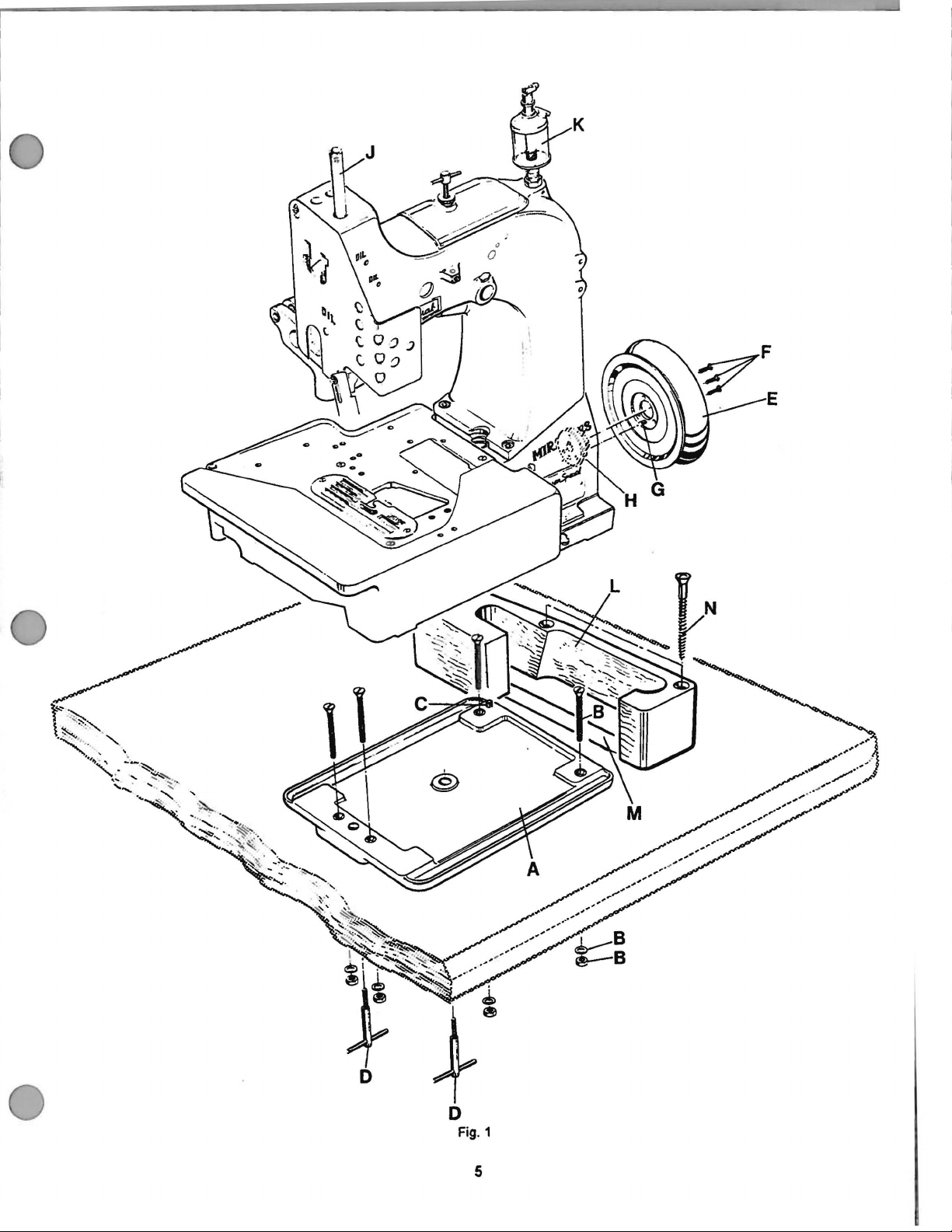
INSTALLATION
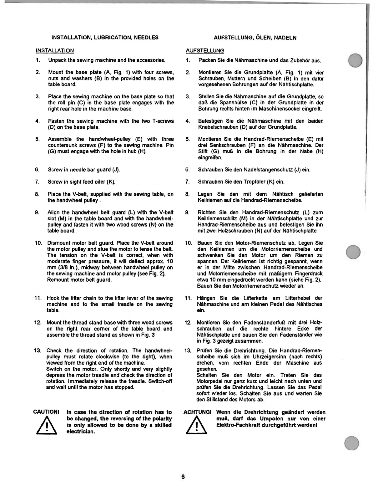
1. Unpack the sewing machine
2.
Mount the base plate
nuts and washers (B) in
table board.
3.
Place
the
sewing
the
roll
right rear hole in the machine
4.
Fasten
(D)
5. Assemble the handwheel-pulley
countersunk screws (F) to
(G) must engage with the hole
6.
Screw in needle bar guard (J).
7.
Screw in sight
8.
Place
the
9.
Align the handwheel belt
slot (M)
pulley and fasten it with two
table board.
pin
the sewing machine with
on
the base
the V-belt, supplied with
handwheel pulley .
in
machine
(C)
in
the base
plate.
feed
oiler (K).
the table board
(A,
and
Fig.
the
provi
on
the
plate
base
the
sewing
in
the
guard
and
with the handwheel-
wood
the
accessories.
1)
with four
ded
holes
base
plate
engages
.
the
two T-screws
(E)
machine.
hub
(H)
.
sewing
(l)
with the V-belt
screws (N)
screws,
on
the
so
that
with the
with three
Pin
table,
on
on
the
AUFSTELLUNG
Packen
1.
Montieren
2.
Schrauben.
vorgesehenen
3.
Steffen
daB
Bohrung
4.
Befestigen
Knebelschrauben
Montieren
5.
drei
Stitt
eingreifen.
6.
Schrauben
7.
Schrauben
8.
Legen
Keilriemen auf
9.
Richten
Keilriemenschlitz (M)
Handrad-Riemenscheibe aus und befestigen Sie
mit
Sie
die
Nahmaschine und
Sie
die
Grundplatte
Muttern
Sie
die
die
Spannhulse (C)
rechts
Sie
Sie
Senkschrauben
(G)
mull in die Bohrung in der
Sie
Sie
Sie
Sie
zwei
Holzschrauben (N) auf der Nahtischplatte.
und
Bohrungen auf der Nahtischplatte.
Nahmaschine auf die Grundplatte,
hinten im Maschinensockel eingreift.
die Nahmaschine mit
(D) auf der Grundplatte.
die
den
den
den
die
den
Scheiben (B)
in
Handrad-Riemenscheibe
(F)
an
Nadelstangenschutz (J)
Tropfoler (K)
mit dem Nahtisch
Handrad-Riemenscheibe.
Handrad-Riemenschutz
in
der Nahtischplatte
das
(A,
Fig. 1) mit vier
der Grundplatte
die Nahmaschine.
ein
.
ZubehOr
in
den
den
(E)
Nabe
ein.
gelieferten
(l)
und
aus
dafOr
so
in
der
belden
mit
Der
(H)
zum
zur
ihn
.
10.
Dismount motor belt guard.
the motor pulley and slue
The
tension on the V-belt is
moderate finger pressure, it will deflect
mm
(3/8 in.
),
the sewing machine and motor pulley
Remount motor belt guard.
11. Hook the
machine
table.
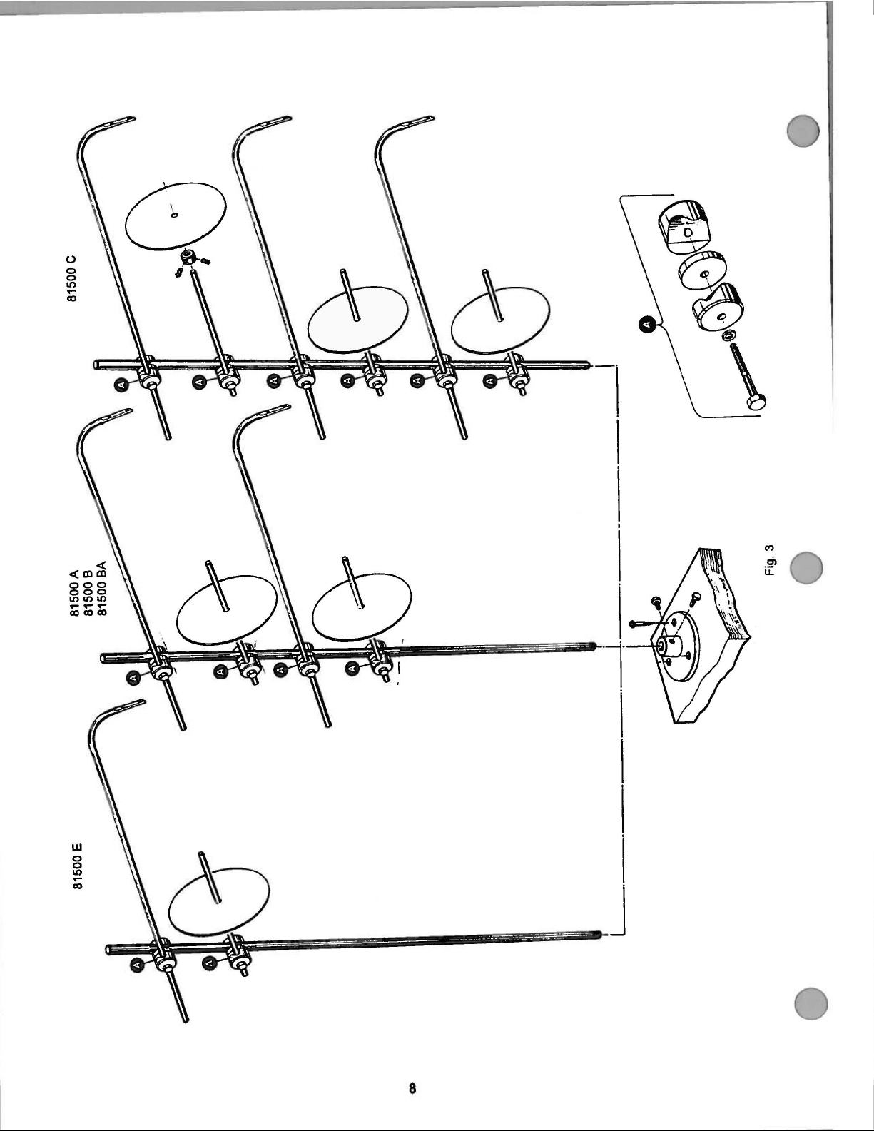
12.
Mount the thread stand base with three
on
the right rear comer of
assemble the thread stand
13.
Check the direction of rotation.
pulley must rotate clockwise (to
viewed
Switch
depress the motor treadle
rotation. Immediately release
and
wait until the motor has
CAUTION I
&
midway between
lifter chain to the lifter lever of
and
to the small treadle
from the right end of
on
the motor. Only shortly
In case the direction
be
changed,
is
only
allowed
electrician.
the
the
as
and
reversing
to
Place
the
motor
the
shown
the
check
the
stopped.
be
V-belt around
to
tense the belt.
correct,
handwheel
(see
on
the
wood
table
in
Fig.
The
handwheel-
the
machine.
right),
and
very slightly
the
direction of
treadle. Switch-off
of
rotation has
of
the polarity
done by a skilled
when
approx.
pulley
Fig.
the
sewing
sewing
screws
board
3
with
10
on
2).
and
when
to
10. Bauen
11.
12.
13. PrOfen
ACHTUNGI
Sie
den
den
Keilriemen
schwenken
spannen.
er
in
der
und
Motorriemenscheibe mit maBigem Fingerdruck
etwa
10
Bauen
Sie
Hangen
Nahmaschine
ein.
Montieren
schrauben
Nahtischplatte
in
Fig
. 3
Sie
scheibe mull
drehen,
gesehen.
Schalten
Motorpedal nur ganz kurz und Ieicht nach
prOfen
Sie
sofort wieder
den
Stillstand
Wenn
mu8,
Elektro-Fachkraft durchgefUhrt werdenl
Motor-Riemenschutz ab.
um
Sie
Der
Mitte zwischen Handrad-Riemenscheibe
mm
eingedrOckt
den
Sie
und
Sie
auf die rechte hintere
gezeigt
die
vom
Sie
die
los
des
die Motorriemenscheibe
den
Keilriemen ist richtig gespannt,
Motorriemenschutz wieder
die Lifterkette am Lifterhebel
den
und
sich
Drehrichtung. Lassen Sie
dart
Motor
werden kann (siehe
am kleinen Pedal
FadenstanderfuB mit
bauen Sie
zusammen.
Drehrichtung. Die Handrad-Riemen-
im Uhrzeigersinn (nach rechts)
rechten Ende der Maschine
den
Motor ein. Treten Sie
. Schalten Sie aus
Motors ab.
die
Drehrichtung geandert werden
das Umpolen
&
um
den
des
den
Fadenstander
und
Legen
Riemen
an.
Nahtisches
drei
Ecke
unten
das
warten
nur
von einer
Sie
und
zu
wenn
Fig. 2).
der
Holz-
der
wie
aus
das
und
Pedal
Sie
6
Page 11
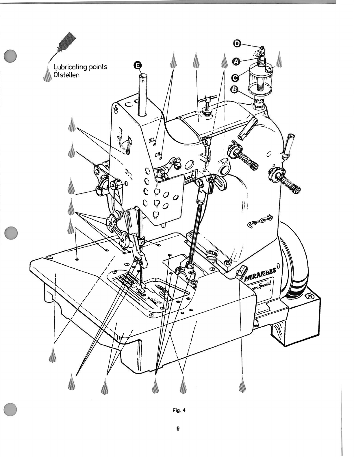
LUBRICATION
Before operating a new machine for the first time, the
sight feed
indicated
For adjusting fill the sight feed oiler half-way with oil
turn the metering pin (A, Fig. 4) a little bit
turn it
minute. This
4).
Fig. 4).
Repeat the oiling of a new machine after
operation!
When the machine is out of operation, the oil flow
stopped by tilting lever
oiler has to be adjusted. All lubrication points,
on
the oiling diagram (Fig.
in,
until there will flow approx. two drops of oil per
can
be
Secure the setting
Fill the oiler.
checked
of
the metering
(D,
Fig. 4)
4),
have
on
the sight glass
pin
with lock nut (C,
to
be
out
and
10
minutes of
oiled. ·
and
then
(B,
Fig
can
be
OLEN
Bevor
eine
geOil
Sie
ein,
kann
werden
neue
wird,
den
den
am
die
(C,
bis
Fig.
Sie
.
nommen
in
der Olanleitung (Fig. 4) angegebenen Schmierstellen
mossen
Fullen Sie
drehen
.
so
weit
Dies
chern Sie
termutter
Wiederholen
einer Betriebsdauer von
Wenn die Maschine nicht
durch Umlegen
stoppt
Maschine zum ersten Mal
muB
der TropfOier eingestellt werden. Aile
werden.
TropfOier
ZumeBstift
pro
Schauglas (B, Fig. 4)
Einstellung des ZumeBstiftes mit der Kon-
4).
bei
des
zum Einstellen halb mit
(A,
Minute etwa zwei Tropfen
Fullen Sie
einer neuen Maschine
Hebels (D, Fig. 4) am TropfOier ge-
Fig. 4) etwas
den
10 Minuten!
in
Betri
Oler.
eb
geprOft
ist,
kann
in
Betrieb ge-
aus
und dann
01
werden. Si-
das
Olen nach
der OlfluB
01
und
flieBen.
IMPORTANT: The
For lubrication we recommend "Mobil
equivalent, which can be purchased from
SPECIAL
G28604l, or in 5 liter containers under part number
G28604L-5.
NEEDLES
Each needle has both a type
number denotes the kind
finish
needle shank, denotes the largest diameter of the
measured midway between the shank
Collectively, type
symbol, which is given
and sold by
Continued
in
and
other details. The
UNION SPECIAL.
on
oil
flow
has
to
be
switched-on
again before operating the machine.
Oil
DTE
Medium" or
and
needle
UNION
The
the
PULLEY
112
liter containers under part number
and
siZe
number.
number, stamped
HANDWHEEL
HANDRAD-RIEMENSCHEIBE
and
page
of
shank, point, length, groove,
siZe
siZe
number represent the complete
on
the label of all
10
type
on
the
blade,
eye.
packs
WICHTIG:
Zur Schmierung empfehlen
ein
oder
112-liter Behaltem unter der Teilnummer G28604L, oder
in 5-Liter
bezogen
NADELN
Jede
Nadel
Typennummer bezeichnet die
Spitze,
Die Dickennummer, im Nadelkolben eingepragt, gibt den
grc5Bten
der Mitte zwischen Kolben und
Dickennummer zusammen ergeben die
Nadelbezeichnung, die auf jedem Etikett aller von UNION
SPECIAL
Lange,
Fortsetzung
ON
SEWING
AN
MACHINE
DER
Der Olflu&
Maschine wieder eingeschaltet werden.
gleichwertiges
Behaltern unter der Teilnummer G28604L-
werden
kann
hat eine Typen- und Dickennummer. Die
mull
YQ! lnbetriebnahme
wir
01,
.
"Mobil Oil
das von UNION SPECIAL
DTE
Art des Nadelkolbens, der
Rinne,
Obertlache
Durchmesser des Nadelschaftes
gepackten und verkauften Nadeln steht.
Seite
1 0
NAHMASCHINE
.
und
andere Einzelheiten.
an,
gemessen in
Ohr. Typen- und
vollstandige
der
Medium"
in
5,
MOTOR
PULLEY
MOTORRIEMENSCHEIBE
Fig. 2
7
Page 12
(.)
0
0
\0
.....
(X)
M
Cl
u:
8
Page 13
/
i' Lubricating points
A Olstellen
~
I
J I !
~
Fig. 4
9
Page 14
The
standard
9859 <3430/172.
The
standard needle for styles 81500
81500 E is 9859 G-300/120.
needle
for styles 81500 A
and
81500
B.
81500 C and
BA
is
Die Standardnadel
BA ist
Die Standardnadel
und
81500 E ist
9859
fOr
<3430/172.
fOr
9859
die Maschinen 81500 A
die Maschinen 81500 8,
G-300/120.
und
81500
81500
c
Type No. Description and sizes
9859
G
Round
300/120) or rounded square point
400/156
spotted, ball
Sizes available: 300/120, 400/156,
To
have
empty package, a sample needle or
number should
label.
A complete order should read as follows:
THREADING
CAUTION: Switch-off
A
~
Styles
threaded
Style 81500 C is threaded
needle orders promptly
"100
~
L.,h actuation
· stopped!
81500
as
shown
shank with
and
eye,
be
forwarded. Use
needles.
OPERATING INSTRUCTIONS
When
A,
using
lock
81500 8, 81500
in
Fig.
seat,
430/172). single
chromium
and
type 9859
main
switch before threading!
clutch
wait
5.
as
shown
round
point (size
plated.
accurately filled,
the
the
BA
type
description
G,
size
motors
until the
and
in
Fig.
5 A
300/120."
motor
81500 E
(sizes
groove.
4301172.
and
size
on
without
has
are
Typen
Nr.
Beschreibung
9859 G
Um Nadelbestellungen richtig und prompt erledigen
an
kOnnen,
eine Musternadel
the
und
Etikett der
Eine vollstandie Bestellung lautet
EINFADELN
ACHTUNG:
&&
Die Maschinen
werden
Die Maschine 81500
eingefadelt.
Rundkolben
spitze (Dicke 300/120) oder verrundete
Vierkantspitze (Dicken
eine
Rinne.
Erhaltliche Dicken: 300/120, 400/156,
senden
Dicke
"100
wie
Sie
ein.
an.
Benutzen
Nadelpackung.
Nadeln.
BEDIENUNGSANLEITUNG
Schalten Sie
Hauptschalter aust Warten
Kupplungsmotoren ohne
sperre den Stillstand des Motors abl
81500
in
Fig. 5 gezeigt,
und
Dicken
mit Befestigungsflache,
Hohlkehle, Ohr verdickt, verchromt.
bitte eine leere Nadelpackung
oder geben Sie die Typennummer
Sie
Type
9589
A,
81500 8, 81500 BA
C wird wie in Fig. 5 A
400/156
die Beschreibung auf
z.
8. wie folgt:
G.
Dicke
vor
dem
eingefadelt.
Rund-
und
430/172),
430/172
zu
oder
dem
3001120."
Einfadeln den
Sie bei
Betatlgungs-
und
81500
gezeigt
.
E
For threading the needle turn handwheel-pulley
rating direction until the needle is in the upmost position.
For looper threading open the hinge plate by lifting locking
bolt knob
Reclose hinge plate after threading.
OPERATING
1.
2.
3.
A
~
* CAUTION! Remove the foot from the motor treadle, to
&
(A,
Figs. 5 and 5 A).
Switch-on main switch.
Without lifting the presser foot, place the fabric to
sewn
as close
to the right
Depress the motor treadle.
Guide the fabric to
CAUTION! Keep a
Ji,
~needle
• in case it is necessary to lift presser foot
&
~
as
possible in front of the
on
the edge guide. •
The
be
sewn.
security
100
mm
(4 in.) between hand and sewing
sewn I
avoid inadvertently starting of the machine,
and
be
when guiding the fabric
upper feed dog for aligning the fabric
sewn!
machine
distance
needle
sews.
of
approx.
in
ope-
and
to
be
be
to
&
Drehen
Riemenscheibe
obersten
Offnen
durch
SchlieBen
wieder.
BEDIENEN
1.
2.
3.
A
~
• ACHTUNGI
Sie
Stellung ist.
Sie
Anheben
SchaHen
Legen
anzuheben
rechts
Treten
Maschine
FOhren
ACHTUNGJ
~
~
•
&
zum
Einfadeln der Nadel die
in
Nahrichtung bis die Nadel
zum
Greifer-Einfadeln die Scharnierplatte
der Griffschraube
Sie
die
Scharnierplatte nach dem
Sie
am
Hauptschalter
Sie
das
Nahgut, ohne dabei den
so
an
dicht wie mOglich vor die
der
KantenfOhrung
Sie
das
naht.
Sie
das
einen Sicherheitsabstand von ca.
mm zwischen Hand und Nahnadel einl
Nehmen
damit die Maschine nicht unabsichtlich
started,
und
Nahgutes anzuheben!
Motorpedal nach
Nahgut.
Halten Sie
Sie
wenn
Obertransporteur zum Ausrichten
(A,
Fig. 5
ein.
an.*
beim
FUhren des Nahgutes
den
FuB
vom
es
notwendig ist,
Handrad-
in
und 5 A).
Einfadeln
DrOckerfuB
Nadel
verne.
Motorpedal.
DrOckerfuB
ihrer
und
Die
100
des
10
Page 15
4.
Release
Cut the thread chain at the trailing
with a pair of scissors and remove the fabric from
the machine.
the motor treadle. The machine
edge
stops
.
of the fabric
4.
lassen
stoppt.
Schneiden
Nahgutes mit einer
das Nahgut
Sie
das Motorpedal los.
Sie
die Fadenkette
von
Schere durch und nehmen Sie
der Maschine.
Die
am
Maschine
Ende
des
NEEDLE THREAD
Basically
5A), located left
cover, is
In
bigger needle thread loop (depending
bric), raise the needle thread take-up roller accordingly.
Fasten the needle thread guide
located
middle of its shank.
THREAD
Regulate the tension
stitches
In general the tension applied to the
slightly higher than the tension applied
thread(s).
Turning the tension nuts clockwise increases the tension,
turning counterclockwise decreases the tension.
CHANGING
CAUTION:
A
~
the needle thread take-up roller
set
case
more needle thread should
on
the top of the upper
TENSION
are
A_
~
TAKE-UP
on
the upper bed casting under
as
low
as
possible.
bed
on
main
actuation
has
stopped!
the threads
switch
produced.
THE
NEEDLE
Switch-off
the
neecllel When using clutch motors
without
motor
(B,
be
pulled off for a
on
thread
(C
, Figs. 5
casting,
so
needle
to
before changing
Jock wait until
Figs. 5 and
the
and
and
approx.
in
that uniform
thread is
the looper
face
fa-
5A),
the
the
NADELFADENABZUG
StandardmaBig
und
5A),
so
tief
wie
Soli
mehr
ge
abgezogen
stellen
Sie
her.
Befestigen
die sich
Mitte ihres
FADENSPANNUNG
Regeln
gleichmaBige Stichbildung erreicht wird.
In
der
Regel
hdher als
Drehen
verstarkt
verringert
AUSWECHSELN
ACHTUNG: Schalten Sie
A
A_
~
~
wird
links
moglich gestellt.
Nadelfaden
die
Sie
oben
Schaftes
Sie
die
die
der
die
sie
.
. gungssperre den Stillstand des
die Nadelfadenabzugsrolle
am
Gehauseoberteil unter
werden
am
ist
auf
Fadenspannungsmuttern im Uhrzeigersinn
Spannung, drehen im Gegenuhrzeigersinn
Nadel den Hauptschalter ausl Warten Sie
bei Kupplungsmotoren ohne Betati-
abl
tor eine groBere Nadelfadenschlin-
(abhangig von
Nadelfadenabzugsrolle entsprechend ho-
die
Nadelfadentohrung
Gehauseoberteil befindet, ungefahr
.
Spannung auf die Faden
die
Spannung auf
den
Greiferfaden (die Greiferfaden).
DER
NADEL
vor
dem
dem
Stirndeckel,
Faden
und
(C, Fig.
so,
den
Nadelfaden etwas
Auswechseln
(8,
Fig. 5
Nahgut),
5 und 5 A),
in
der
daB eine
der
Motors
Turn the handwheel pulley in operating direction until the
needle is
Unthread the
loosen
out the needle. Insert the shank of the new
as
to the front (toward the operator). Tighten screw (D)
the seat of the needle shank and thread the
CAUTION:
&
• ·
EDGE
Styles 81500
Fig.
Style 81500 E
Set the edge guide (A, Figs. 6 and 6 A) laterally
as possible to the presser foot, without contacting
When looseni
can be moved laterally. Retighten screws.
in
its upmost position.
eye
of
screw
it
will go
and
~
&
GUIDE AND STITCH TONGUE
6.
the needle to be changed.
(D,
Figs. 5 and 5A) for the
with the long groove of the
Switch-Off
ting
changing
clutch
wait
A,
81500
see
Fig. 6 A.
ng
the two screws (B), the
edge
motors
until
the
guide
the
the
motor
B,
81500 BA
seam
needle
and
needle
needle
needle
eye.
main switch before set-
and stitch tongue and
wldthl
without
has stopped!
When using
actuation lock
and
81500
as
edge
guide (A)
C,
pull
as
far
facing
on
see
close
it.
Sie
Drehen
bis die
Fadeln
LOsen
und
ziehen
del
so
lange
son) zeigt
gungsflache
delohr
WICHTJG:
A
~
KANTENFOHRUNG
Maschinen
siehe
Maschine
Stellen
dicht
berohren.
KantenfQhrung
die Schrauben wieder an.
die Handrad-Riemenscheibe in Nahrichtung
Nadel
in
Sie
Sie
ein,
Rinne
ein.
A.
~
Fig.
Sie
wie
ihrer oberen Stellung
das
Ohr der zu wechselnden Nadel
die
Schraube
Sie
die
daB
der Nadelkolben
der Nadel nach vorne (zur Bedienungsper-
Ziehen
am
Nadelkoben fest und tadeln
Schalten Sie
tenfuhrung und Stichzunge und
dern
· aus! Warten Sie bei Kupplungsmotoren
ohne Betatigungssperre den
Motors abl
81500
6.
81500
Nach
A,
E siehe Fig. 6
die
KantenfOhrung
m6glich
LOsen
(A) seitlich verschoben werden. Ziehen Sie
ist
(D.
Fig.
Nadel heraus. Setzen Sie die neue Na-
Sie die Schraube (D) auf der Befesti-
der
Nahtbreite den Hauptschalter
UNO
STICHZUNGE
81500
an
den
der beiden Schrauben (B) kann die
5 und 5A)
oben
vor
dem
B,
81500 BA
A.
(A, Fig. 6 und
DrOckerfuB,
Einstellen
aus
.
fOr
die Nadel
anstoBt und die
Sie
das Na-
von
Kan-
dem
An-
Stillstand des
und
81500
SA)
seitlich so
ohne diesen
C,
zu
Continued
on
Page 14
Fortsetzung
Seite
11
14
Page 16
f
I
I
I
i
f
THREADING
EINFADELANLEITUNG
DIAGRAM
FOR
FOR
STYLES
DIE
MASCHINEN
81500
A,
81500
81500
8,
A,
81500
81500
Fig. 5
BA
8,
and
81500
81500 E (81500
BA
unci
81500 E (81500
12
E
Is
without
E ist
looper
ohne
thread)
Greiferfaden)
Page 17
?~-
:
~
.
: :
~
I
I
'
I
I
! I
I I
! I
:;
I
~--··
·
·~--
.....
.. ..
.--:.::::.
---
....
-·
~--
.
· ·
•'·
· '
LE
THREADINGN~~;~~
EINFADELA
:g:
81500C C
~r
MASCHINE
A
81500
Fig.
SA
13
Page 18
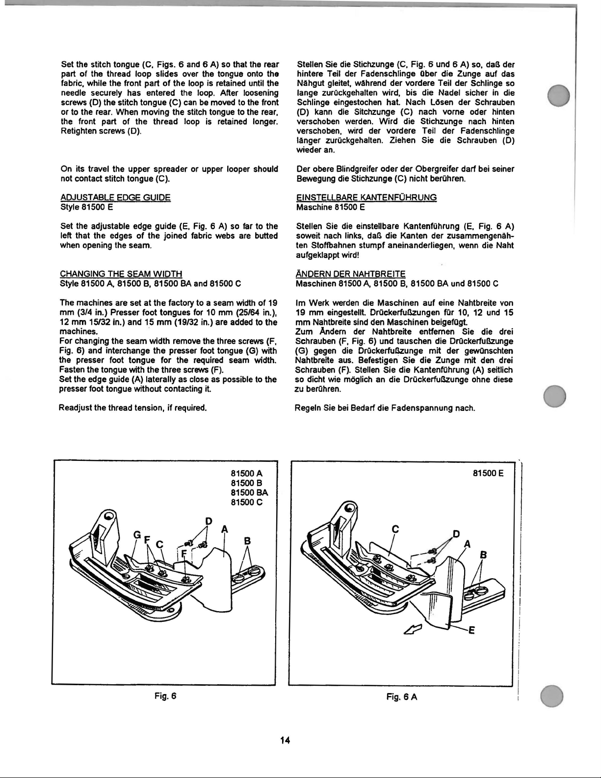
Set the stitch tongue (C, Figs. 6 and 6 A) so that the rear
part
of
the thread loop slides over the tongue onto the
while the front part
fabric,
needle securely has entered the loop. After loosening
screws (D) the stitch tongue (C) can be moved to the front
or to the rear . When moving the stitch tongue to the rear,
the front part
Retighten screws (D).
of
of
the loop is retained until the
the thread loop is retained longer.
Stellen Sie die Stichzunge (C, Fig. 6 und 6 A) so, daB der
hintere
Nahgut gleitet, wahrend der vordere Teil der
lange
Schlinge eingestochen hat. Nach
(D) kann die
verschoben werden.
verschoben, wird der vordere
Ianger zurOckgehalten. Ziehen Sie die Schrauben (D)
wieder
Teil der Fadenschlinge
zurOckgehalten wird, bis die Nadel sicher
Sitchzunge (C) nach vorne oder hinten
Wird
an
.
Ober
die Zunge auf das
LOsen
die Stichzunge nach hinten
Teil der Fadenschlinge
Schlinge so
der Schrauben
in
die
On its travel the upper spreader or upper looper should
not contact stitch tongue
ADJUSTABLE EDGE
Style 81500
Set the adjustable edge guide (E, Fig. 6 A) so far to the
left that the edges
when opening the seam.
CHANGING THE SEAM
Style 81500
The machines are set
mm
(3/4 in.) Presser foot tongues for 10 mm (25/64 in.),
12
mm
machines.
For changing the seam width remove the three screws (F,
6)
Fig.
the presser foot tongue for the required seam width.
Fasten the tongue with the three screws (F).
Set the edge guide (A) laterally as close as possible to the
presser foot tongue without contacting
Readjust the thread tension,
E
A.
81500 8, 81500
15132
in.) and 15
and interchange the presser foot tongue (G) with
(C)
.
GUIDE
of
the joined fabric webs are butted
WIDTH
8A
and 81500 C
at
the factory to a seam width
mm
(19/32 in.) are added to the
it.
if
required.
of
19
Der obere Blindgreifer oder der Obergreifer
Bewegung die
EINSTELLBARE
Maschine
Stellen Sie die einstellbare Kantenfahrung (E, Fig. 6 A)
soweit nach links,
ten Stoffbahnen stumpf aneinanderliegen, wenn die Naht
aufgeklappt wird!
ANDERN
Maschinen
lm
Werk werden die Maschinen
mm
19
mm
Nahtbreite sind den Maschinen beigefOgt.
Zum
Andern der Nahtbreite entfernen Sie die drei
Schrauben (F, Fig. 6) und tauschen die DrOckerfuBzunge
(G)
gegen die DrOckerfuBzunge
Nahtbreite aus. Befestigen
Schrauben
so dicht wie
zu
berOhren.
Regeln Sie
Stichzunge (C) nicht berOhren.
KANTENFOHRUNG
81500 E
daB die Kanten der zusammengenah-
DER
NAHTBREITE
81500A, 81500 8, 81500 BA und 81500 C
eingestellt. DrOckerfuBzungen
auf
mit
Sie die Zunge mit den drei
(F). Stellen Sie die KantenfOhrung (A) seitlich
moglich an die DrOckerfuBzunge ohne diese
bei
Bedarf die Fadenspannung nach.
dart bei seiner
eine Nahtbreite von
fOr
10, 12 und 15
der gewOnschten
Fig. 6
81500A
81500 8
81500 BA
81500 c
14
Fig.
81500 E
6A
Page 19

MAINTENANCE
WARTUNG
CAUTION! Switch-off Mainswttch before doing ACHTUNGI Schalten Sie
/':\.
~
LUBRRICATION AND CLEANING
The machines of class 81500 have to
lubricated twice a day before morning
on
(Fig.
should
oil
of
Also refer to paragraph "LUBRICATION"
INSTALLATION, LUBRICATION, NEEDLES".
A.
6
· the
the lubricati
4).
The
be
per
minute.
the
oil
are
maintenance
motors
motor
on
points indicated
sight
adjusted
The
oiler has to
used
up.
worksl
without
has stopped! den Stillstand des
feed
oiler
so,
that it feeds
When using clutch ·•
actuation
has
be
refilled latest.
lock
be
and
on
the oiling di
to
be
kept filled
two
to three
cleaned
afternoon start
in
walt until
and
agram
and
drops
of
when
213
section
A.
ill
A.
~
OLEN
UNO
Die
Maschinen
vor
der
gereinigt
angegebenen
muB
bis drei
nachgetollt
sind.
Siehe
"AUFSTELLUNG,
lnbetriebnahme am Morgen und Nachmittag,
und
gefQIIt
Topfen
werden,
auch
Hauptachalter ausl Warten Sle bel
lungsmotoren ohne
REINIGEN
der
Klasse 81500
an
den
Stellen
und
so
eingestellt sein,
01
wenn
Absatz "OLEN" im Abschnitt
OLEN, NADELN.
fliel!.en. Der Oler
vor
Wartungsarbeiten den
Betltlgungssperre
Motors
mOssen
in
geschmiert werden.
der Olanleitung (Fig.
daB
213
der Olmenge verbraucht
mull
Kupp-
abl
zweimal
pro Minute zwei
taglich,
Der
TropfOier
spatestens
4)
15
Page 20

INSTRUCTIONS
FOR
MECHANICS
MECHANIKERANLEITUNG
A A
~ ~
Before adjusting the machine remove the face cover and
the finger guard left on the machine head, the upper feed
dog, the presser foot, the cloth plate with hinge plate and
throat plate, the feed dog, the throat plate support with
front needle guard and the rear needle guard .
Insert a new needle!
Refer to paragraph
"OPERATING INSTRUCTIONS".
SETIING
1. Styles 81500
The lower looper (A, Fig. 7)
offset flats on its shank for adjusting the looper
spectively the looper point with respect to the needle.
Insert the lower looper (A) into the rear hole of looper
lever (B). Now snug the set screw
the looper lever against the flat on the looper shank
(E) so that the point
close as possible to the spot on the back
needle (N), without deflecting
cond screw (D) firmly.
1.1. Rotate handwheel-pulley in operating direction until
the needle just starts from its lowest position moving
upward.
point
should
If adjustment is necessary loosen nut (G,
move the ball stud (H)
looper lever (B) accordingly until the distance of
mm
Observe
king
THE LOWER LOOPER
the
SAFETY RULES when
adjustments.
"CHANGING THE NEEDLE" in section
A,
81500
B,
81500 BA and 81500 C.
of
these styles has two
(C) at the back
of
the lower looper passes as
it.
Now tighten the se-
In
this position the distance between the
of
the looper and the center
be
11
mm
(7/16 in.) (see Fig.
of
ball joint (J) in the slot
(7/16 in.) is reached. Retighten nut (G).
of
the needle
8).
Fig.
ma_,
re-
of
the
7) and
of
11
of
A A Beachten Sie
~
~
wenn sie
Entfernen Sie vor
deckel und den Fingerabweiser links am Maschinenkopf, den
oberen Transporteur. den
Scharnierplatte
StichplattenstOtze mit vorderem Nadelanschlag
hinteren Nadelanschlag
Setzen Sie eine
Siehe Absatz "AUSWECHSELN DER NADEL" im Abschnitt
"BEDIENUNGSANLEITUNG".
EINSTELLUNG
1. Maschinen 81500
Der Untergreifer (A, Fig. 7) dieser Maschinen hat am
Schaft zwei versetzte Befestigungsflachen zum Einstellen des Greifers bzw. der Greiferspitze im Bezug
zur Nadel.
Stecken
rung des Greiferhebels (B). Legen Sie
windestift (C) hinten im Greiferhebel (B)
tigungsflache
Untergreiferspitze so dicht wie moglich in der
kehle auf der Ruckseite der Nadel (N) vorbeigeht, ohne diese abzulenken. Ziehen Sie jetzt die zweite
Schraube (D) gut an.
1.1 Drehen
tung bis die Nadel gerade beginnt aus ihrer untersten
Stellung nach oben zu gehen.
der Abstand zwischen Greiferspitze und Nadelmitte
mm betragen (siehe Fig. 8).
1st
eine Einstellung notwendig, losen Sie die Mutter
(G, Fig. 7)
Kugelgelenks (J) im Langloch des Greiferhebels (B)
entsprechend, bis der Abstand von
Ziehen Sie die Mutter (G) wieder fest.
dem
und
neue
DES
Sie
den
des
Sie
die
und
verschieben die Kugelschraube (H) des
die
SICHERHEITS-HINWEISE,
Elnstellarbeiten
Einstellen der Maschine
DrOckerfull, die Stoffplatte mit
Stichplatte, den Transporteur, die
Nadel ein!
UNTERGREIFERS
A,
81500
Untergreifer (A) in die hintere Boh-
Greiferschaftes (E)
Handrad-Riemenscheibe
machenl
B,
81500 BA
so
In
dieser Stellung soli
11
mm
den
und
81500C.
nun
den
an
der Befes-
an,
in
Nahrich-
erreicht
und
daB
Hohl-
Stirn-
den
Ge-
die
11
ist
Style 81500
2.
The lower spreader (A, Fig. 7
only one seat on its shank.
Insert the lower spreader
hole
seat
screw (C).
The point of the lower spreader must pass as close
as possible to the spot on the back
without deflecting it.
If
adjustment is necessary loosen set screws
7 A) and move looper lever (B) on its cone shaft
accordingly. Retighten set screws (K).
The distance
between the point
needle is set as described in item 1.1.
E.
of
looper lever (8). Tighten screw (D) on the
of
the lower spreader shank, then tighten set
of
11
mm
of
spreader and the center of the
A)
of
this style has
(A,
Fig. 7 A) into the rear
of
the needle (N),
(7/16 in.) (see Fig. 8 A)
(K,
Fig.
2.
Maschine 81500 E
Der untere Blindgreifer
hat nur eine Befestigungsflache am
Stecken Sie den unteren Blindgreifer
die hintere Bohrung des Greiferhebels (B). Ziehen
Sie die Schraube (D)
unteren Blindgreiferschaftes an und dann den Gewindestift
Die Spitze
moglich in der Hohlkehle
(N) vorbeigehen, ohne diese abzulenken.
stellung notwendig, losen Sie die Gewindestifte (K,
Fig. 7A)
ner Konuswelle entsprechend. Ziehen Sie die Gewindestifte (K) wieder
Der Abstand von
Blindgreiferspitze und Nadelmitte wird, wie unter Punkt
1.1. beschrieben, eingestellt.
(C).
des
unteren Blindgreifers
und
verschieben den Greiferhebel (B) auf sei-
(A,
Fig. 7 A) dieser Maschine
auf
der Befestigungsflache
auf
der ROckseite der Nadel
an.
11
mm
(siehe Fig. 8 A) zwischen
Schafl
(A,
Fig. 7 A) in
mull
so
1st
des
dicht wie
eine Ein-
16
Page 21

Fig
N
. 7
View
Ansicht
81500A
81500 8
81500 8A
81500 c
"X"
"X"
D
.,
Fig
. 7 A
.
I
'
81500
E
81500A
81500 8
81500
81500 c
81500 A
81500 8
81500
81500 c
8A
8A
Fig. 8
j._11mm
81500 E
81500 E
Fig.
~11mm
SA
Fig.
9
17
Fig.
9A
Page 22

SETIING
THE HEIGHT
OF
THE NEEDLE BAR
EINSTELLUNG DER NADELSTANGENHOHE
Rotate handwheel-pulley in operating direction until the
of
point
spreader
in.) to the right from
edge
must be flush in this position.
If
10)
(B) up or down, as required. Care should be taken not
disturb the alignment
adjustment. Retighten clamp screw.
SETIING
Styles
Before inserting a new upper spreader
thread hook (B). This facilitates the visual check
adjustment.
For adjustment
needle (N), the shank
Proceed as follows :
First snug one screw
spreader shank with which
spreader is reached:
When rotating the handwheel-pulley in sewing direction,
spreader
close as possible
contacting it. Now tighten
firmly.
lower looper (A, Fig. 9) or the point of lower
(A, Fig. 9
of
looper/ spreader and upper edge of needle eye
an adjustment is necessary loosen clamp screw (A, Fig.
in
the needle bar connection and move the needle
THE UPPER SPREADER
81500
(A,
A.
81500 B.
of
Fig.
A)
projects 1 to 1,5
the
right side
of
the
needle bar when making this
81500
spreader
11
to
(A.
of
A)
the
Fig. 11) with respect to
spreader (A) has two offset flats.
(C, Fig. 11) on the flat
the
should pass with its face (D)
front
the
second screw (C. Fig. 11)
mm
of
the needle. Lower
BA and 81500 E
(A, Fig. 11) remove
following position
of
needle (N), without
(.040 to .060
bar
to
of
the
the
of
the
of
the
as
Drehen Sie an der Handrad-Riemenscheibe in
Nahrichtung bis die
oder die
bis 1,5 mm rechts von der rechten Seite
In dieser Stellung mOssen Unterkante Greifer/ Blindgreifer
und Oberkante Nadelohr bundig sein .
1st
Klemmschraube
und schieben
oben oder unten. Beachten
die Ausrichtung der Nadelstange nicht verandert wird.
Ziehen Sie die Klemmschraube wieder an.
EINSTELLUNG DES OBEREN BLINDGREIFERS
Maschinen 51500 A, 81500 B, 81500
Bevor
einsetzen entfernen Sie den Fadenhaken (B). Dies
erleichtert die visuelle Prufung der Einstellung.
Zum Einstellen des Blindgreifers (A, Fig. 11)
Nadel (N) hat der
versetzte Befestigungsflachen.
Gehen Sie wie folgt vor:
Legen Sie zuerst eine Schraube (C, Fig. 11) auf der
Flache des Blindgreifers an,
des Blindgreifers erhalten:
Beim Drehen der Handrad-Riemenscheibe
mull
(D) dicht an der Vorderseite der Nadel (N) vorbeigehen,
ohne diese zu berOhren. Zief'!en Sie nun die zweite
Schraube (C), Fig. 11)
Spitze des unteren Blindgreifers (A, Fig. 9 A) 1
eine Einstellung notwendig, losen Sie die
Sie einen neuen oberen Blindgreifer (A, Fig. 11)
der Blindgreifer (A, Fig.
Spitze des Untergreifers (A. Fig. 9)
der
Nadel
stehl
(A.
Fig. 10)
Sie die Nadelstange (B) entsprechend nach
Schaft des Blindgreifers (A) zwei
gut
im
Nadelstangenmitnehmer
Sie,
dall
bei dieser Einstellung
BA
und 81500 E
mit
der
Sie folgende Stellung
11
A)
mit
seiner Stirnflache
an.
im
Bezug zur
in
Niihrichtung
HINT:
In
case the adjusting possibility
means
of
the two offset flats
not
sufficient, additionally the complete bearing
is
(A,
Fig. 12) can be
loosening screws (B). Retighten screws.
In the extreme lett upper end position
11) the distance between
of
and the center
If
an adjustment ist necessary, loosen nuts (L and
12) and turn connecting rod (C) forward
required
Note: The left nut (L) has a lett hand thread. Temporarily
snug the two nuts (L and
Remount thread
it so that its tip passes close behind the needle without
contacting it (see Fig .
to
needle
obtain the required position.
hook
moved
the
bottom of the forked cut-out
(N)
should be 6
R)
manually.
(B. Fig. 11)
11 A).
of
the spreader
on
the spreader shank
slightly up
on
or
down when
of
spreader
mm
(15/64 in.)
or
backward as
spreader (A) and set
(A,
R,
by
Fig.
Fig.
HINWEJS: Sollte die Einstellmoglichkeit des Blindgreifers
mit
Hilfe der beiden versetzten Befestigungsfliichen
am Greiferschatt nicht ausreichen, kann, nach
der beiden Schrauben (B, Fig.
ganze Lager (A) etwas nach oben oder unten
verschoben werden.
Schrauben wieder an.
In
der aullerst linken oberen Endstellung des Blindgreifers
(A,
Fig. 11)
des gabelformigen Einschnittes und der Nadelmitte (N) 6
mm
Wenn eine Einstellung notwendig ist
(L
und
vor oder zurOck bis die erforderliche
Beachten Sie: Die Iinke Mutter (L) hat ein Linksgewinde.
Legen
an.
Montieren
Blindgreifer (A) und stellen
dicht hinter der Nadel vorbeigeht, ohne diese zu berOhren
(siehe Fig.
mull
der Abstand zwischen der tiefsten Stelle
betragen.
R,
Fig. 12) und drehen
Sie vorerst beide Muttern (L und R) von Hand Ieicht
Sie den Fadenhaken (B. Fig. N) wieder an den
11
A).
Ziehen Sie die beiden
die
Sie ihn so,
12)
zusatzlich das
Jasen
Verbindungsstange (C)
Sie die Muttern
Stellung erreicht
dall
LOsen
isl
seine Spitze
18
Page 23

D
Fig.
10
81500
A
81500 B
81500
BA
81500 E
81500 A
B
81500
81500 BA
E
81500
81500 c
Upper looper in left
upper end position
Obergreifer in linker
oberer Endstellung
Fig.
B
11
gap
Luftspalt
Fig.
A
11
A
Fig.
11
8
Fig.
11
C
19
Fig_
12
Page 24

Rotate handwheel-pulley in sewing direction until the
upper spreader is in its extreme right lower
The upper spreader should
during its motion.
If
required loosen clamp screw (D, Fig. 12) in the drive
lever (E) and set the lever so that the upper spreader (F)
clears at
all points. Retighten clamp screw.
not
contact any machine parts,
end
position.
Drehen Sie
Nahrichtung bis der obere Blindgreifer in seiner
rechten unteren Endstellung ist. Der obere Blindgreifer mit
Fadenhaken darf bei seiner Bewegung keine
Maschinenteile
Bei Bedarf
Antriebshebel (E) und
Blindgreifer (F)
Klemmschraube wieder an.
an
der Handrad-Riemenscheibe in
berOhren
IOsen
an
.
Sie die Klemmschraube (D, Fig. 12) im
stellen den Hebel so, daB der obere
allen Stellen freigeht. Ziehen Sie die
auBerst
of
After this setting recheck the positon
spreader to the needle, as described above. Reset with
connecting rod
and R).
Rotate handwheel-pulley in sewing direction.
upward travel
A) the tip
possible in the recess behind the eye
(A, Fig.
(A, Fig. 13 A) without contacting it.
If
an adjustment is required, loosen nut (G, Fig. 7) and
swing the looper lever with lower looper accordingly to the
or
left.
right
CAUTION! Check the setting
SETTING THE UPPER LOOPER
81500 C
Style
Preliminary mount the upper looper (A,
thread hook (B) to the looper shank
distance (T) between upper looper and thread hook
big as possible.
(C,
Fig. 12)
of
the
of
its lower prong (G) must pass as close as
UP,per
if
required and tighten nuts (L
spreader
(B,
of
13), respectively in the recess
of
after making this adjustment and reset
required. Refer
HEIGHT OF THE NEEDLE BAR".
the needle bar height
to
paragraph "SETTING THE
the upper
Figs. 13 and
the lower looper
on
Fig
(S) so that the
On the
lower spreader
.
11
B)
and the
is
13
as
PrOfen Sie nach dieser Einstellung nochmal die Stellung
des oberen Blindgreifers zur Nadel, wie eben beschrieben.
Stellen Sie bei Bedarf mit der Verbindungsstange
12) nach und ziehen Sie die Muttern
Drehen Sie
Nahrichtung.
(B, Fig.
unteren
Aussparung hinter dem
bzw. in der Aussparung am unteren Blindgreifer (A, Fig.
an
Bei
der Handrad-Riemenscheibe in
der Bewegung des oberen Blindgreifers
13 und 13 A) nach oben
Zinkens (C) so dicht wie mOglich in der
Ohr
des Untergreifers
(Lund
R)
mull
die Spitze seines
13 A) vorbeigehen ohne diesen zu berOhren.
1st
eine Einstellung notwendig, losen Sie die Mutter (G,
Fig. 7) und schwenken Sie den Greiferhebel (B) mit dem
Untergreifer entsprechend nach rechts oder links.
Sie
Mutter (G) wieder an.
ACHTUNGI
if
EINSTELLUNG DES OBERGREIFERS
Maschine 81500 C
Montieren
Fadenhaken (B) vorlaufig so an den Greiferschaft (S), daB
der Abstand (T) zwischen Obergreifer und Fadenhaken
groll
PrOfen
Sie nach dieser Einstellung die Nadelstangenhohe und
Siehe Absatz "EINSTELLUNG DER NADELSTANGENHOHE".
Sie
den
Obergreifer (A, Fig.
wie moglich ist.
stellen Sie bei Bedarf nach.
11
an.
(A,
B)
(C,
Fig.
Fig. 13)
Ziehen
und
den
so
of
For adjustment
to the needle (N) the looper shank
flats.
Proceed as follows:
First snug one screw
(S) with which the following position
shank
looper is reached:
When rotating the handwheel-pulley in sewing direction,
upper looper
as close as possible to the front
contacting it. Now tighten the second screw (C, Fig.
firmly.
For precise adjustment
respect
upper looper (A) accordingly.
Simultaneously set the thread hook (B, Fig.
its tip passes close behind the needle (N) without
contacting it. Retighten the two screws (U).
HINT: In case the adjusting possibility
to
as described is not sufficient, additionally the
bearing
down when loosening the
screws.
upper looper (A, Fig.
(C, Fig.
(A, Fig.
the needle (N) loosen screws (U) and set the
(A, Fig. 12) can
11
11
C) should pass with its face (D)
of
upper looper (A, Fig.
two
11
B) with respect
(S) has
B)
on
of
needle (N), without
the flat
of
two
of
the upper
11
11
C) so that
of
the upper looper
be
moved slightly up or
screws (B). Retighten
offsett
looper
11
B)
C) with
Zum Einstellen
zur
Nadel (N) hat der Greiferschaft (S) zwei versetzte
Befestigungsflachen.
Gehen
Sie wie folgt vor:
Sie zuerst eine Schraube (C, Fig.
Legen
Flache des Greiferschaftes
Stellung des Obergreifers erhalten:
Beim Drehen der Handrad-Riemenscheibe in Nahrichtung
mull
der Obergreifer (A, Fig.
(D) dicht an der Vorderseite der Nadel (N) vorbeigehen,
ohne diese zu
Schraube (C, Fig.
Zur Feineinstellung des Obergreifers (A,Fig.
Bezug zur Nadel (N)
den
stellen
Stellen Sie gleichzeitig den Fadenhaken (8, Fig.
daB seine Spitze dicht hinter der Nadel (N) vorbeigeht,
ohne diese zu
(U) wieder
HINWEIS: Sollte die EinstellmOglichkeit des Obergreifers
wie beschrieben nicht ausreichen, kann, nach Losen
der beiden Schrauben (B, Fig.
ganze Lager (A) etwas nach eben oder unten
verschoben werden. Ziehen
wieder
des
Obergreifers (A, Fig.
(S) an
11
C)
berOhren. Ziehen Sie nun die zweite
11
B)
gut an.
IOsen
Obergreifer (A) entsprechend.
berOhren.
an.
Sie die Schrauben (U) und
Ziehen Sie die zwei Schrauben
11
mit
der Sie folgende
mit
seiner Stimflache
12), zusatzlich das
an.
Sie die Schrauben
11
B)
B)
11
1m
11
Bezug
auf
C) im
C)
der
so,
20
Page 25

A C
Fig.
13
81500 A
81500 8
81500
8A
A C
Fi
g.
13
81500 E
A
Fig.
13
81500 c
81500 A 81500 BA
81500 8 81500 c
B
A
8
Fig. 14
··
..
....
_______
_
Fig. 15
21
Fig.
B
16
Page 26

In the extreme left upper end position
11
Fig.
eye and the center
in.)
If
B), the distance between the left edge
an adjustment is necessary, loosen nuts (L and
of
needle (N) should
of
upper looper (A,
of
be
6 mm (15/64
looper
R,
Fig.
12) and turn connecting rod (C) forward or backward as
required to obtain the required position.
Note: The left nut (L) has a left hand thread. Temporarily
snug the two nuts
Rotate handwheel-pulley in sewing direction until the
upper looper is in its extreme right lower
upper looper with thread hook should not contact any
machine parts during its motion.
If
required loosen clamp
lever (E) and set the lever
clears at
all points. Retighten clamp screw.
(Land
R) manually.
end
screw
(D. Fig. 12)
so
that the upper looper (F)
position. The
in
the drive
In
der auBerst linken oberen Endstellung des Obergreifers
(A,
Fig.
11
B)
mull
des Greiferohrs und der Nadelmitte (N) 6
Wenn eine
(L
und
R,
Rig. 12) und drehen die Verbindungsstange (C)
vor oder
Beachten
Legen
an.
Drehen
tung bis der Obergreifer in seiner
Endstellung ist. Der Obergreifer
seiner Bewegung keine Maschinenteile beruhren.
Bei Bedart
Antriebshebel (E) und
Obergreifer (F)
Klemmschraube wieder an.
zurOck
Sie:
Sie vorerst beide Muttern (L und R) von Hand Ieicht
Sie
der Abstand zwischen der linken Kante
Einstellung notwendig ist ll:isen Sie die Muttern
bis die ertorderliche Stellung erreicht ist.
Die
Iinke Mutter (L) hat ein Linksgewinde.
an
der Handrad-Riemenscheibe in Nahrich-
mit
ll:isen
Sie die Klemmschraube (D. Fig. 12) im
an
stellen den Hebel so, daB der
allen Stellen freigeht. Ziehen Sie die
mm
betragen.
auBerst rechten unteren
Fadenhaken dart bei
After this setting recheck the position
the needle,
(C, Fig.
Rotate handwheel-pulley in sewing direction. On the
upward travel
must pass as close as possible in the recess
eye
If
an adjustment is required, loosen nut (G, Fig. 7) on the
double joint and swing the looper lever with lower looper
accordingly to the right
CAUTION! Check the setting
SETIING
Styles
The thread retainer (B, Fig.
looper thread before the lower looper (A) enters into the
needle thread loop.
Viewed from the left end
retainer (B) should pass as close as possible
side
contacting
a~
described above. Reset with connecting rod
12)
if
required and tighten nuts
of
upper looper (B, Fig. 13 B) its tip (C)
of
the lower looper (A) without contacting
or
left. Retighten nut (G.)
after making this adjustment and reset
required. Refer to paragraph
HEIGHT
THE THREAD RETAINER
81500
A,
OF
THE NEEDLE BAR
81500 B, 81500
14) should retain the lower
of
of
lower looper (A) when swinging upward without
it
.
of
the spreader to
(Land
R).
behind
the
it
of
the needle bar height
"SETIING
".
BA
and 81500 C
the machine the thread
on
THE
the left
Profen Sie nach dieser Einstellung nochmal die Stellung
des Blindgreifers zur Nadel, wie oben beschrieben. Stellen
bei Bedart mit der Verbindungsstange (C, Fig. 12)
Sie
nach und ziehen
Drehen
tung. Bei der Bewegung des Obergreifers (B. Fig.
nach oben
der Aussparung hinter dem
beigehen ohne diesen
1st
Fig. 7) am Doppelgelenk und schwenken
greiferhebel mit dem Untergreifer entsprechend nach
rechts oder links.
ACHTUNGI Prufen Sie nach dieser Einstellung die Na-
if
EINSTELLUNG
Maschinen 81500
Der Fadenholer
rOckhalten ehe der Untergreifer (A)
schlinge eintritt.
Vom linken Ende der Maschine aus gesehen soli der Fa-
denholer (B) bei seinem
mOglich an der linken Seite des Untergreifers (A) vorbeigehen, ohne diesen zu
Sie
eine Einstellung notwendig,
Sie die Muttern
an
der Handrad-Riemenscheibe in Nahrich-
mull
seine Spitze (C) so dicht wie moglich in
zu
Ziehen Sie Mutter (G) wieder an.
delstangenhohe und stellen
Siehe Absatz "EINSTELLUNG
nach.
NADELSTANGENHOHE".
DES
FADENHOLERS
A,
81500
(B.
Fig. 14) soli den Untergreiferfaden zu-
Schwenk nach oben, so dicht wie
berOhren.
(Lund
R) an.
Ohr
des Untergreifers (A) vor-
beruhren.
IOsen
Sie die Mutter (G,
B,
81500 BA und 81500 C
in
die Nadelfaden-
Sie den Unter-
Sie bei Bedart
13
DER
B)
On the most upward travel
the thread retainer (B) should
below the underside
contact neither the throat plate nor the feed dog.
After loosening screw (C, Fig.
be
moved to the left
can
flat
of
the thread retainer shank.
After loosening the two set screws (D), shaft (E) with the
thread retainer (B) can be rotated into the correct position.
Make sure to remove
the set screws.
of
its swing motion the tip
be
of
the throat plate. It should not
as close
as
possible
14) the thread retainer (B)
or
right
Retighten screw
all lateral end play when tightening
on
the
of
Am
hOchsten Punkt seiner Schwenkbewegung
Spitze des Fadenholers (B) so dicht wie moglich unter der
Unterseite der Stichplatte liegen.
platte noch den Transporteur berahren.
Nach
Losen der Schraube (C. Fig. 14) kann der Fadenho-
ler (B) nach links oder rechts verschoben werden. Ziehen
Sie
die Schraube wieder
Fadenholerschaftes an.
LOsen
Nach
(E) mit dem Fadenholer (B) in die richtige
dreht werden. Achten Sie beim Anziehen der Gewindestifte darauf, daB kein seitliches Spiel vorhanden ist.
der belden Gewindestifte (D) kann die Achse
22
Er
dart
weder die Stich-
auf
der Befestigungsflache des
Stellung ge-
mull
die
Page 27

SETTING THE LOWER FEED DOG
The
lower feed dog (A, Fig. 15) should center laterally in
the
slots
of
loosen the two (set) screws (C) and move
to
the left or right as required. Retighten (set) screws.
throat plate (B).
If
an adjustment is necessary.
feed
rocker (D)
EINSTELLUNG
Der untere Transporteur
der Stichplatte (B) seitlich vermittelt sein.
lung notwendig
ben (C) und schieben den Transportantriebsrahmen (D)
nach Bedarf nach links oder rechts. Ziehen
(Gewindestifte) Schrauben wieder an.
DES
UNTEREN TRANSPORTEURS
(A,
Fig. 15) muB in den Schlitzen
IOsen
Sie die beiden (Gewinde) Schrau-
1st
eine
Einstel-
Sie die
At
highest point
dog
(A, Fig. 15) should
above the top surface
Adjust the supporting screw (C) in the
quired height and assemble
THROAT PLATE SUPPORT AND BRACKET FOR
FRONT
Assemble the throat plate support
bracket (B) for the front needle guard
interfere with the feed dog
SETIING
Rotate handwheel-pulley in operating direction until the
rear
position.
contact the back
After
(A)
Retighten screw.
NOTE: Any change in stitch length necessitates a corre-
NEEDLE GUARD
needle guard
In
loosening screw (B, Fig. 17) the rear needle guard
can
be
sponding change in the rear needle guard setting.
of
feed travel the rear teeth of the feed
just
of
THE REAR NEEDLE GUARD
(A,
this position its guarding surface should just
moved accordingly to the front or to the rear.
Fig. 17) is
of
needle (N) without deflecting
project their full depth (F)
throat plate.
the
or
any other machine parts.
feed
feed
dog.
(A,
Fig.
so
that they
in
its most forward end
bar to the re-
16)
and
do
it.
the
not
lm hochsten Punkt der Transportbewegung
hinteren
Zahnhohe (F)
Stellen Sie die Stotzschraube (E) im Transporteurtrager
auf die entsprechende
Transporteur.
STICHPLATIENSTOTZE UNO WINKEL
REN NADELANSCHLAG
Monti
Winkel
den Transporteur noch andere Maschinenteile
EINSTELLUNG
Orehen Sie
bis der hintere Nadelanschlag (A, Fig. 17) in seiner
dersten Endstellung
Schutzflache die
ohne sie abzulenken.
Nach
Nadelanschlag (A) entsprechend nach verne oder hinten
geschoben werden. Ziehen
BEACHTEN SIE: Jede Anderung der Stichlange erfordert
Zahne
des
Transporteurs (A, Fig. 15) gerade eine
Ober
die Stichplattenoberflache ragen.
Hohe und montieren Sie den
eren
Sie die StichplattenstOtze (A, Fig. 16) und den
fOr
den
vorderen Nadelanschlag so,
DES
HINTEREN NAOELANSCHLAGS
die
Handrad-Riemenscheibe in Nahrichtung
ist
In
ROckseite der Nadel (N) gerade berOhren
LOsen
der Schraube (B, Fig. 17) kann der hintere
ein
hinteren Nadelanschlags!
dieser Stellung soli seine
Sie die Schraube wieder
entsprechendes Nachstellen des
sollen
FOR
daB
sie
berOhren.
die
VORDE-
weder
vor-
an.
SETIING
The front needle guard (C, Fig. 16) is set close to the
needle (N) just contacting
After
be adjusted accordingly. Retighten screw.
SETTING THE UPPER FEED DOG
Assemble the upper feed dog (B, Fig. 18) and the presser
foot (C) . The upper feed dog (B) should not push against
the front or rear end when moving in the slots of presser
foot (C).
Simultaneously the upper feed dog
positioned
tooth spaces
it. When the lower feed dog (A) is in its highest and the
upper feed dog (B) in its lowest point of travel, there must
be a small gap between both feed dogs.
The feed travel
should be synchronous.
THE FRONT NEEDLE GUARD
the
needle without deflecting
loosening screw (D)
so
that the tips
of
the lower feed dog (A), without contacting
of
the
of
the upper and the lower feed dog
it
front needle guard (C) can
(B,
its teeth engage with the
Fig. 19) should be
EINSTELLUNG
Der vordere Nadelanschlag (C, Fig. 16) wird
die Nadel (N) gestellt,
sie abzulenken.
Nach
LOsen
schlag (C) entsprechend eingestellt werden. Ziehen
die Schraube wieder an.
EINSTELLUNG
Montleren Sie
On1ckerfuB
Bewegung in den
vorne noch hinten anstoBen.
Gleichzeitig muB der Obertransporteur (B,
positioniert
ZahniOcken des unteren Transporteurs (A) eingreifen, ohne diesen
in der
hOchsten
tersten Stellung seiner Bewegung ist, muB zwischen beiden Transporteuren ein Luftspalt sein.
Der Transportweg von oberem und unterem Transporteur
muB gleich (synchron) sein.
DES
VORDEREN NADELANSCHLAGS
so
Fig.
dicht an
19)
daB er diese gerade berOhrt ohne
der Schraube
DES
den
(C). Der Obertransporteur (B) darf bei seiner
sein,
daB die Spitzen seiner Zahne in die
zu
ben1hren.
und der Obertransporteur (B) in der un-
(0)
kann der vordere Nadelan-
OBEREN TRANSPORTEURS
Obertransporteur (B, Fig. 18) und den
Schlitzen
im
DrOckerfuB (C) weder
Wenn der untere Transporteur (A)
Sie
so
23
Page 28

-
_,___(1~
I
•-
•
:.
• •
~
N
··.
·····
·•
I
-·~------
Fig.
Fig. 17
18
Fig.
19
Fig.
21
24
Fig. 20
Fig. 22
Page 29

For
setting the upper feed dog with respect to the slot
ends
in
feed
(E) accordingly to the front or rear. Retighten screw.
the presser foot and the tooth spaces of the lower
dog,
loosen screw
(0,
Fig. 18) and tum drive lever
Zum Einstellen
Schlitzenden im DrOckerfuB und zu den ZahniOcken des
unteren Transporteurs,
18) und schwenken
nach vorne oder hinten. Ziehen
des
Obertransporteurs
IOsen
den
Antriebshebel (E) entsprechend
im
8ezug
Sie die Schraube
Sie Schraube
wieder
zu den
(0,
an.
Fig.
For
setting the small gap between the
nut
(F,
Fig. 20). Turning in screw (G) increases the gap,
turning it out decreases the gap. Retighten nut (F).
For
matching the upper feed dog travel with the lower feed
dog travel loosen screw (A. Fig.
in the slot
upper feed dog travel, moving
travel. Retighten screw (A).
HINT:
are set
however,
upper feed dog travel in order to get a proper
matching
Also refer
LENGTH".
UPPER FEED DOG MOTION
Style
On
this style the upper feed dog does not lift on its return
travel.
parallel to the height
ALTERNATING UPPER FEED DOG AND PRESSER
FOOT
Styles
of
rocker lever
(8)
to the front decreases the
it to the rear increases the
In
general the travels
equally. Depending
it
may be necessary to set a slightly longer
of
the fabric plies.
to
of
lower
on
paragraph "CHANGING STITCH
81500 A
It works as a so-called shirring upper
of
the presser foot.
81500 8, 81500 8A. 81500 C and 81500 E
feed
dogs loosen
21
). Moving the ball link
and
upper
feed,
feed
be
moving
the fabric to
dog
sewn
end
Zum
Einstellen
IOsen
Sie die Mutter
(G) vergroBert
Sie die Mutter (F) wieder an.
Ziehen
Zum Angleichen des Obertransportwegs an
unteren Transporteurs
Verschieben
vorne verldeinert
vergrOBert
hinten
an.
HINWEIS: Normalerweise werden die Transportwege von
unterem Transporteur und Obertransporteur gleich
eingestellt. Abhangig vom Nahgut kann
erforderlich
groBer einzustellen um Lagenverschiebungen
auszugleichen.
Siehe auch Abschnitt "ANDERN DER STICHlANGE".
OBERTRANSPORTEURBEWEGUNG
Maschine 81500 A
Bei dieser Maschine hebt der Obertransport beim
ROckweg
Obertransport, der sich parallel
DrOckerfuBes
AL TERNIERENDER OBERTRANSPORTEUR UNO
DROCKERFUSS
Maschinen 81500 8, 81500 BA. 81500 C und 81500 E
des
Luftspalts zwischen den Transporteuren
(F,
Fig. 20). Eindrehen
Luftspalt, Herausdrehen verkleinert ihn.
IOsen
Kugelgelenks im Kulissenhebel (B) nach
den
ihn. Ziehen Sie die Schraube
Er arbeitet als sogenannter Schlepp-
Sie die Schraube (A, Fig.
Obertransportweg, verschieben nach
den Obertransporteurweg etwas
zur
nicht
den
des
sein,
ab.
bewegt.
der
Schraube
den
Weg des
(A)
wieder
es
jedoch
Hohe des
21
).
On these styles
are alternating on the fabric
While the upper feed dog feeds, the presser foot lifts from
the
fabric to be sewn.
lifts from the fabric
dog
lowers on the fabric to hold it.
For
adjustment
dog
and
and raise the supporting yoke (J) when the upper
lift more and the
should
the upper feed dog should
more. Retighten screws (H).
PRESSER FOOT PRESSURE
Rotate the handwheel until the lower feed dog is below the
throat plate. Loosen knurled nut
T-screw (B) until
leaf springs.
presser foot should be
bottom and the front end
squarely on the throat plate.
By relocating the collars (C, Fig. 23) which serve as a leaf
spring rest, on the left and right presser bar, the pressure
can be changed. Raising the collars increases the
pressure, lowering the
the
upper feed dog and the presser foot
to
be
sewn.
On
its return travel the upper feed
to
be sewn
of
presser foot loosen the two screws
the alternating lift motions
pressP.r
liu less and the presser foot
and
the presser foot
foot less, or lower it when
(A,
Fig. 22) and tum out
it does not escert any pressure on the
In
this position, the pressure excerted
so
strong that the presser foot
of
the presser foot tongue rest
collars decreases
it.
of
upper feed
(H,
Fig. 20)
feed
on
dog
the
8ei diesen Maschinen sind der Obertransporteur und der
DrOckertuB wechselweise auf dem Nahgut.
Wah rend der Obertransporteur transportiert hebt
DrOckerfuB vom Nilhgut a b.
der Obertransporteur vom Nahgut ab und der
senkt sich zum Festhalten auf das Nahgut.
Zum Einstellen der alternierenden Hubbewegung von
Obertransporteur und
Schrauben
hOher,
DrOckerfuB weniger abheben soli, oder stellen Sie es tiefer
wenn der Obertransporteur weniger und der
mehr abheben soli. Ziehen Sie die Schrauben (H) wieder
an.
DR0CKERFUSSDRUCK
Drehen
der
Stichplatte steht.
22) und drehen
daB sie nicht mehr auf die Blattfedern drOckt. In dieser
Stellung soli der Druck auf den DrOckerfuB
daB die DrOckertuBsohle und das vordere Ende der
DrOckertuBzunge flach auf der Stich platte aufliegt.
Durch Verstellen der als Blattfederauflage dienenden
Stellringe
DrOckerfuBstange, kann der Druck verandert werden.
Verstellen der Stellringe nach oben verstArkt, verstellen
nach unten verringert den Druck.
(H,
wenn der Obertransporteur mehr und der
Sie
Fig. 20) und stellen das Stotzlager (J)
am
Handrad bis der untere Transporteur unter
Sie die Knebelschraube (B) soweit heraus,
(C,
Fig.
Auf
seinem
DrOckerfuB losen Sie die beiden
LOsen
Sie die Riindelmutter (A. Fig.
23)
auf
der linken und rechten
ROckweg
der
hebt
DrOckertuB
DrOckeruB
so
stark sein,
25
Page 30

Th.: presser foot lift is limited with the upper stop collar
(D, Fig. 23)
in its lowest position and the presser foot is lifted
presser foot lifter lever, the needle holder should not
tact the presser foot. Besides this, the lifted presser foot
should not contact the right upper spreader or upper
looper moving upwards.
dingly.
Make sure that both presser bars move
freely without binding.
on
the right presser bar. When the
Set the stop collar (D) accor-
up
and down
needle
with the
con~,
is
Der Hub des
ring (D, Fig. 23)
begrenzt. Wenn die Nadel in der untersten
und der
hoben wird, darf der Nadelhalter den DrOckerfuB nicht berOhren
oben gehenden rechten oberen 81indgreifer oder Obergreifer nicht berohren. Stellen Sie den Anschlag-Stellring
(D) entsprechend
Oberzeugen Sie sich, daB sich beide DrOckerfuBstangen,
ohne zu klemmen, auf- und abbewegen.
DrOckerful!.es
oben
DrOckerfuB
. Zudem darf der geliftete DrOckerfuB
mit dem DrOckerfuB-Litterhebel ange-
ein.
wird
mit
auf der rechten DruckerfuBstange
dem Anschlag-Stell-
Stellung ist
den
nach
Now turn in T-screw (8, Fig. 22) until the necessary
presser foot pressure for proper feeding is excerted
(determine by
knurled nut (A) which simultaneously fastens the upper
arm cover. Remount the face cover and the finger guard.
CHANGING STITCH LENGTH
The length of the stitch can be adjusted by raising or
lowering stud
rocker (C) located at the rear
plate. Lowering stud (A)
the stud
stud (A) can
stitch length is obtained, retighten nut (8).
NOTE: Any char.ge in stitch length necessitates a
sewing tests). Secure this setting with the
(A,
Fig. 24) in the segment slot of
will shorten the stitch. After loosening nut (8),
be
moved accordingly. When the desired
corresponding change in the rear needle guard
setting and matching
travel.
Refer to paragraphs
NEEDLE GUARD" and
DOG".
FEED
of
machine below the cloth
will lengthen the stitch, raising
of the upper
"SETTING THE REAR
"SETTING THE UPPER
feed
feed
dog
Nun drehen
ein, daB der zum einwandfreien Transport notwendige
DrOckerfuBdruck erzeugt
teln). Sichern Sie diese Einstellung mit der Randelmutter
(A), mit der gleichzeitig der obere Armdeckel befestigt
wird. Montieren
wieder.
ANDERN
Die Stichliinge
8olzens
rahmens (C), hinten
te, verandert werden. Tieferstellen des 8olzens (A) ver-
langert
der Mutter
schieben. Wenn die gewonschte Stichlange eingestellt
ziehen Sie die Mutter
BEACHTEN
Sie die Knebelschraube (8, Fig. 22) soweit
wird (durch Nahversuche ermit-
Sie
den
Stirndeckel und den Fingerschutz
DER
STICHLANGE
kann
(A,
Fig.
den
Stich, HOherstellen verkOrzt ihn. Nach
(8)
SIE: 8ei jeder Anderung der Stichlange
durch Hoher- oder Tieferstellen
24) in der Nut des Transportantriebsan
der Maschine unter der Stoffplat-
laBt sich der Bolzen (A) entsprechend ver-
(8)
wieder an.
der hintere Nadelanschlag entsprechend
nachgestellt und der Obertransportweg
angeglichen werden!
Siehe Absatze "EINSTELLUNG
HINTEREN NADELANSCHLAGS"
"EINSTELLUNG DES
PORTEURS".
08EREN
des
Losen
ist,
muB
DES
und
TRANS-
A-J.--~.IW'
B
Fig. 23
26
'LJ.~-r-tr-
Fig.
24
Page 31

ORDERING REPAIR
PARTS
BESTELLUNG VON ERSATZTEILEN
ILLUSTRATIONS
The following section
spare
and
sections of the mechanism are shown
may
machine.
found a listing of the parts with their part numbers, descriptions
ticular
Numbers
and
illustration. Reference numbers should never
ordering parts. Always use the part number listed
second
Component parts
furnished for repairs are indicated
description under the description of the main
assembly.
18
19
20
21
Where the construction permits,
with its part number.
where the construction does not permit, are marked
identification letters, to distinguish the part from similar
ones
presser foot tongue, part
repair parts. Exploded views of various
be
seen
On
the page opposite the illustration will
and
view being shown.
in
the first column are reference numbers only,
merely indicate the position of that part
column.
As
an
G15442 P
81345•
G15442 R
22729
(e.g. "GP" thread hook, part
of
this manual simplifies ordering
so
in
their actual position
the number
example refer to the following text:
Ball Joint Assembly
Ball Stud
Shell
Screw
of
pieces required
of
sub-assemblies which
Some smaller parts and parts
No.
each
81597 A-19).
that the parts
in
by
indenting their
part is stamped
No.
81310, 'WL-19"
the sewing
in
be
be
the par-
in
the
used
in
the
can
be
sub-
with
ABBILDUNGEN
Der folgende
Bestellung
onszeichungen der einzelnen Gruppen des Mechanismus zeigen die
ne.
Auf der der Bildseite gegenOberliegenden
findet sich
Beschreibungen
schnitt benotigten
Die Nummern
und
mern
in
zu
finden ist. Positionsnummern
lungen
Teilenummer
Einzelteile
werden
bung
unterhalb der Beschreibung des Kompletteiles ge-
kennzeichnet. Als Beispiel siehe folgenden Text:
Kugelgelenk komplett
Sofern
ner Teilnummer gekennzeichnet. Einige kleine Teile und
Teile wo
Kennbuchstaben gezeichnet,
zu
Teilen
Nr.
81310, 'WL-19" DrOckerfuBzunge, Teil
19).
Teil
dieses Handbuches vereinfacht die
von
Verschleil!- und Ersatzteilen. Explosi-
Lage
der Einzelteile
ein
Verzeichnis der Teile mit Teilnummern,
und
der
Anzahl.
in
der ersten Spalte sind Positionsnum-
zeigen
lediglich, wo das Teil
nie
verwendet werden. Verwenden Sie immer die
in
der
von
Kompletteilen, die als Ersatzteile geliefert
konnen,
Kugelschraube
Lagerschale
Schraube
es
sind durch
die Konstruktion erlaubt ist jedes Teil mit sei-
es
die Konstruktion nicht erlaubt sind mit
unterscheiden
fOr
zweiten Spalte.
urn
(z.
B.
in
der Nahmaschi-
den
gezeigten Bildaus-
in
dOrfen
bei Teilebestel-
EinrOcken
das Teil von ahnlichen
"GP" Fadenhaken, Teil
ihrer Beschrei-
Seite
be-
der Abbildung
1
2
1
4
Nr.
81597 A-
At the back of the
index of all parts shown in this manual. This will
facilitate locating
only a part number is known.
IMPORTANT! ON ALL ORDERS,
manual will
the illustration
PART NUMBER, PART NAME,
QUANTITY REQUIRED AND STYLE OF
MACHINE FOR WHICH
ORDERED.
be
found
a numerical
and
description when
PLEASE
INCLUDE
PART IS
Am Ende
verzeichnis
Dies erleichtert
schreibung,
WICHTIG!
des
samtlicher im Handbuch dargestellter Teile.
wenn
Handbuches befindet sich ein Nummern-
das
Auffinden der Abbildung
nur eine Teilenummer bekannt ist.
BITTE
GEBEN SIE AUF ALLEN BESTELLUNGEN
LEBESCHREIBUNG, DIE BENOTIGTE
MENGE
FOR
AN.
DIE TEILENUMMER,
UNO
DEN
DEN MASCHINENTYP,
DAS
TEll
BESTELL T WIRD ,
und
DIE
Be-
TEI-
27
Page 32

E/{PlOSIO~ISlElCl-1-
. .
f'IUf'IGEf'l
28
Page 33

Torque
to
25
Nm
(221
and
secure with
engineering adhesive
No.
g99-114
Mit
25
Superschnell-Konstruktions-
kleber Teil
gesichert.
Nm
angezogen
8.
Nr. 999-114
in.lbs.)
superfast
part
und
mit
-~
.............
~,...
....
6
The
rear
of
the
must
sit
the counterbore
casting,
Die
Ruckseite des Buchsenbundes
muB
in
der
gehiuse anliegen,
gepresst.
close
when
pressed
Ansenkung
bushing
to
of
the
the
wenn
collar
bottom
bed
in.
im
GuB-
ein-
of
29
eeee
~~~1
41
42
43
40
Page 34

Ref.
No
Pos.
20
21
22
23
24
25 22539
27
28
29 22596 D
30
31
32
33
34
35
36.
37
38
39
40 80689 A
41
42
43
44
45
NOTE
Part
Nr.
TeiiNr
1 •
80862
81373 A
2*
80293 A
3
4 22894 K
5 22894
6 666-79
7 80846
8
9
10
11
•
12.
13
14
15
16
17.
18.
19
26.
: Bushings marked with
bed
to order the followi
required amount
and
89
80644
88
80640
80694 DA
M 129
TR118
999-216 E
95861
80692 EA
81240 DA
29111
81261
81260
15465 F
88
12987 A
80694 DA
80885
80885
999-106 D
80885 B
22891
80885 A
HA
81
HA
95
81394 B
M 129 KD
M 129 K
666-197
80689 c
80689 D
80690A
15430 L
3090021
casting. Instead of single bushings
instructions.
No.
.
J
EA
c
B
c
KR
BUSHINGS.
Description Beschreibung Amt.
Presser Bar Bushing
Needle Bar Bushing
Oil Distributor Olverteiler 1
Spot
Screw,
Set Screw Gewindestift 1
Sight
Bushing for
Spot
Plug
Set Screw Gewindestift 2
Bushing, left for upper
Bushing, right for upper
Sticker "OIL" Aufldeber "OIL" (01) 4
Transfer
Plug VerschluBstopfen 1
Screw
Bushing for
Bushing for looper drive rocker shaft
Bushing
for looper lever Greiferhebel
Bushing
Cone
Cone
Set Screw Gewindestift 2
Nut Mutter 2
Plug
Bushing for crankshaft, left
Ball Bearing Assembly for crankshaft Kugellager komplett
Retaining
Screw Schraube 3
Deep
Hub
Screw Schraube 2
Bearing
Spot
Screw,
Set Screw Gewindestift 1
Bushing for crankshaft, middle
Transfer
Style Plate Typenschild 1
Grooved Drive Pin
Oil
Cup
Spring Valve Oiler Kugeloler 2
Spring Valve Oiler
Oil Cup Klappoler 1
Felt Filz 2
Cotton
an
asterisk are cemented
ng
repair sets which include the der
of
bushings with engineering adhesive Reparaturslitze
headless Gewindestift mit Spitze 1
Feed
Oiler Tropfoler 1
needle
Screw,
headless Gewindestift mit Spitze 2
Screw VerschluBschraube 2
feed
and
Cone Shaft assembly
Shaft Konuswelle 1
Screw VerschluBschraube 2
Ring
Groove Ball Bearing Rillenkugellager 1
headless Gewindestift mit Spitze 1
MIRAKLES Abziehbild MIRAKLES 1
Swab
(as required) Watte (nach Bedarf)
SIGHT FEED
BUCHSEN.TROPFOLER.OLER
lever shaft
feed
drive shaft
feed
drive shaft
rocker shaft
we
in
recommend
the
OILER.
OILERS
Buchse
Buchse
Buchse
Buchse,
Buchse,
Abziehbild 1
Schraube
Buchse
Buchse
Buchse
Buchse
Konus
Buchse
Haltering 1
Nabe
Lager
Buchse
Kerbnagel
Klappoler 2
KugeiOier
BEACHTEN
Buchsen
einzelnen
Anzahl
Anleitung enthalten.
fOr
DrOckerfuBstange 4
fOr
Nadelstange 2
fOr
Nadelhebelwelle 2
links far Obertransport-Antriebswelle 1
rechts
fOr
Obertransport-Antriebswelle 1
fOr
Transportrahmenwelle 2
tar Greiferantriebs-Schwingwelle 2
und
Konuswelle komplett tar 1
fOr
Kurbelwelle, links 1
fOr
Kurbelwelle, Mitte 1
SIE: Mit einem Sternchen bezeichnete
sind im GuBgehause eingeklebt. Anstelle
Buchsen mit Konstruktionskleber
fOr
Kurbelwelle 1
Buchsen empfehlen wir folgende
zu
bestellen, welche die benotigte
Reg
Anzahl
3
1
1
1
1
2
4
und
.
29916 RED
29916 REF
REM
29916
29916 REL
29916 RER
29916 RET
IMPORT ANTI When cementing align the
bushings
casting I
Presser Bar Bushings( Ref.
Needle Bar Bushings
Bushings for upper
(Ref
Nos.
11
and
Bushings for
(Ref.
Bushings for looper drive rocker shaft
(Ref.
Bushings for crankshaft (Ref.
and
36)
with
the
No.
17)
No
. 18)
oil
holes In the
feed
12)
rocker shaft
oil
No.
(Ref. No. 2)
feed
drive shaft
holes In
bed
Nos.
the
1)
Buchsen
Nadelstangenbuchsen (Pos. Nr. 2)
Buchsen
(Pos. Nrn. 11
Buchsen
(Pos
Buchsen
(Pos. Nr.
26
Buchsen
und
WICHTIGI Rlchten Sle
fOr
DruckerfuBstangen (Pos. Nr. 1)
fOr
Obertransport-Antriebswelle
far Transportrahmenwelle
. Nr. 17)
far Greiferantriebs-Schwingwelle
18)
fOr
Kurbelwelle (Pos. Nm.
36)
30
und
12)
26
beim
Einkleben die
rungen In den Buchsen
bohrungen
lm
GuBgehluse
zu
den
ausl
1
1
1
1
1
Olboh·
01-
Page 35

•
Page 36

CLOTH PLATE, BASE PLATE, GUARDS AND MISCELLANEOUS COVERS
STOFFPLATTE,
GRUNDPLATTE, SCHUTZTEILE UNO VERSCHIEDENE ABDECKUNGEN
Ref. No Part No. Description
Pos. Nr.
18 G
20
Teil Nr.
1 80673 CB
2 80888 Arm Cover
3
4 35733 B Knurled Nut
5 81387 Face Cover
6
7
8
9
10 80437 A Hinge Pin
11
12 81239
13
14
15
16
17
19 21681
64Y
22528
A9453A
AS 126 Washer
81301 D Cloth Plate Assembly
88 B
80438 Spring
80440 Locking Bolt Knob
22574
80280 A
96664
105B
G 50-42
Needle Bar Guard Nadelstangenschutz
T-Screw Knebelschraube
Screw Schraube
Finger Guard
Set Screw
Locking
Countersunk Screw
Plate Grundplatte
Base
Roll Pin
Screw with Nut and Washer
T -Screw for sewing machine
Pin Stitt 1
Bolt
Beschreibung
Armdeckel
Randelmutter
Stimdeckel
Fingerabweiser
Scheibe
Stoffplatte komplett
Scharnierstift
Gewindestift
Rastbolzen
Feder 1
Griffschraube
Senkschraube 3
SpannhOise 1
Schraube mit Mutter und Scheibe
Knebelschraube
fOr
Rastbolzen 1
fOr
Nahmaschine
Amt. Reg.
Anzahl
1
1
1
1
1
2
1
1
1
1
2
1
1
4
2
32
Page 37

..
·~
~
(,
.. ' t
•
38
Page 38

Ref.
No
Part No.
~
Pos. Nr. Teil Nr.
1
HS 106
80669 B
2
80676A
3
4
80676 B
HA
5
6
7
8
9
10
11
12
13
14
15
16
17
18
19
20
21
22
23
24
25
26
27
28
29
30
31
32
33
34
35
36
37
1349
HS
110 A
110-3
110-2
107
108
80667
81256A
22560 8
81256 B
28C
AS
136
22560 8
AS 135
HA
103 B
28C
22894
81559
BP
108
22894 y
22894 w
81254 8
80665 D
80668
88
HS
538
22560
HA
1286 B
12954 c
81086 G
22894
81267
93A
AD
AD
THREAD TENSION AND
FADENSPANNUNGS- UNO FADENFOHRUNGSTEILE
Description
Tens ion
Tension
Tension
Tension Disc
Tension
Spring for
Styles
Spring for
Style 81500 E
Spring
Styles 81500
Tension Spring Ferrule, Styles
Tension
Pin for Tension Discs, Styles
Thread
Set Screw
Thread Sleeve for looper thread
Styles 81500
Set
Holder, Style 81500 A. 8,
Set Screw for Holder
Holder
Eyelet
Set Screw for Eyelet
Set Screw
Needle
Eyelet
Needle
Take-up Roller
Set Screw
looper
81500 A.
Screw
Post, Styles 81500 A,
Post Ferrule, Styles
Disc, Styles 81500
Style 81500 A
Sleeve, Styles 81500 A. 8, SA
Needle Thread Tension, all
except 81500 E
Needle Thread Tension,
for
Looper Thread Tension,
A.
81500 c
Nut, Styles 81500 A.
Sleeve for needle thread
A.
81500 c
Screw for Thread Sleeve
81500 c
Bar
Hex. Head Cap Screw
Set Screw
Set Screw
Set Screw
Roller Stud Assembly
Connection
Thread Take-up Roller Assy.
Set Screw
Spring
Spring
Ball
Roller Stud
Thread Guide, Styles
B,
BA. C
81500 A,
81500 c
81500 E
8, BA
81500 A,
81500 c
81500 E
81500 c
81500 E
81500 A,
81500 c
81500 E
8,
SA
81500 c
81500 E
81500 c
81500 E
81500 c
81500 E
SA
.
8,
8, SA
8,
SA
B,
SA
B,
B,
BA
THREAD
BA
BA
GUIDE PARTS
Besch rei bung
Spannungsbolzen, Maschinen 81500
HOise
fOr
Spannungsscheibe Maschinen
Spannungsscheibe,
FederhOise Maschine
tor Nadelfadenspannung, aile 1
Feder
Maschinen auBer 81500 E ·
Feder
fOr
81500 E
Feder
fOr
Maschinen 81500 A,
Spannungsfeder-HOise,
Spannungsmutter,
Stift for Spannungsscheiben, Maschinen
Fadenhulse tor Nadelfaden
Gewindestift
FadenhOise tar Greiferfaden
Maschinen
Gewindestift
Maschinen 81500 A, B.
Halter,
Gewindestift
Halter
Fadenose
Gewindestift
Gewindestift
Nadelstangenmitnehmer
Sechskantschraube
Gewindestift
Gewindestift
Fadenose
Nadelfadenabzugsrolle
Abzugsrolle
Gewindestift
Rollenbolzen
Gewindestift
Feder
Federkugel
Rollenbolzen
Gewindestift
Greiferfadentohrung,
81500
A.
Schraube
A,
81500 c 3
Spannungsbolzen, Maschinen
Maschine
81500
81500
81500
Nadelfadenspannung, Maschine
Greiferfadenspannung
81500 c 2
81500 A, B.
81500C
tor
fOr
fOr
fOr
B,
SA
81500
81500
81500
Maschine
81500
81500
81500
BA
FadenhOise
81500 c
Halter
Fadenose
Fadenose
komplett
komplett
Maschinen
81500 E 1
81500
A,
81500
c 3
81500
E 1
81500 B,
81500 A 4
A,
B,
c 3
E 1
Maschinen
A.
B,
c 3
E 1
81500 A.
81500
81500 E 1
A,
c
E
BA
B,
B,
SA
81500 c 6
81500
BA
E 2
BA
BA
B.
c 3
B,
BA
8, BA. C
Amt.
Anzahl
BA
SA 2
1
2
2
1
1
1
1
1
1
1
1
1
1
1
2
2
4
2
1
2
2
3
1
1
1
1
2
1
1
2
1
1
1
1
1
1
1
Ref. Nos. 38 - 46, see
page
36
Pos. Nrn. 38 - 46, siehe
34
Seite
36
Page 39

16
<
-~.
(,. ' \
Page 40

Ref. No Part No. DescriPtion
Pos.
Nr
.
Teil Nr.
Ref. Nos. 1 - 37, see page
38 81256 A
81254 A Eyelet for looper threads,
39
40
22894AD
41
81252
42 81392 Looper Thread Guide,
43
44
45
46
88 Set Screw Gewindestift
81350 0
80696 Stud
99623A
34
Sleeve for looper thread, Fadenhulse tor Greifertaden, Maschinen
Thread
Styles 81500
Style 81500 C Maschine 81500 C
Set Screw Gewindestift
Looper Thread Guide,
81500
A,
B,
looper
Thread Guide
Spacer for lower looper thread
tension post,
A,
B,
BA 81500
BA
Style 81500 C
Styles GreiferfadenfOhrung,
Style 81500 C GreiferfadenfOhrung, Maschine 81500 C
Beschreibung
Pos. Nrn.
FadenfOhrung
81500
GreiferfadenfOhrung
Bolzen
Distanzbuchse
Spannungsbolzen, Maschine
A.
A,
1-37,
B,
BA
B,
BA
fOr
fOr
siehe Seite 34
Greifertaden,
unteren Greiferfaden-
Amt. Beg .
~
1
1
1
1
1
1
1
1
1
81500 C
36
Page 41

Torque to 2,2-2,4 Nm (19,5-21 ln.lbs.)
Mit
2,2 bis 2,4 Nm angezogen
Torque to 3,8-4 Nm (33,5-35,5 in.lbs.)
Mit 3,8 bls 4 Nm angezogen
Torque to 3,8 Nm (33,5 in.lbs.)
Mit 3,8
Nm
angezogen
32
Torque to
Mit
.
~53
2,2 Nm (19,5 in.lbs.)
2,2 Nm angezogen
Torque
to
Mit 3,8 Nm angezogen
"!/'
I
3,8 Nm
~-.'r'48'
....
\
..._
(33,51n.lb~)~
54
Shell of needle lever ball link should be
positioned with an angle
lation to the shell on the crankshaft.
Die Lagerschale des Kugelgelenks
hebel
mul?.
im
schale auf
185mm
7
9132
Winkel von 7° 48' zur Lager-
der
Kurbelwelle stehen.
in.
of
7° 48' in re-
am
Nadel-
37
Page 42

NEEDLE
NADELSTANGE, NADELHEBEL, KURBELWELLE, HANDRAD- RIEMENSCHEIBE
Ref.
No
Pos. Nr. Teil Nr.
19
20
21
22
23
24
24A
25
26
27
28
29
30
31
32
33
34
35
36
37
38
39
40
41
42
43
44
45
46
47
48
49
50
51
52
53
54
55
56
57
58
59
60
61
62
Part No.
1 81317 Needle Bar
2
80566
3 22536
81518 Needle Holder Nadelhalter
4
5 96 B Set Screw for needle for all Styles Gewindestift tar Nadel
6
HA61D
7 G 89
8 81559 Needle Bar Connection Nadelstangenmitnehmer
BP108
9
22894 y
10
22894W
11
12
HA54A
34334 v Link Pin
13
14
15
16
17
18
666-149
80715 Needle Lever
22894 y
22894 c
22894J
22894 H Set Screw
96653 Roll Pin SpannhOise 1
BP108
80643
80776
80774 Guide for all Styles except 81500 A
22882 Hex. Head Cap Screw
80772
80771 Link for all Styles except 81500 A
34334 v Link Pin for all Styles except 81500 A
666-149 Oil
80770 Lift
22894 y
80769 Sliding Block for all Styles exc. 81500 A Gleitstein
80768 Supporting Yoke for all Styles except
79
80732
22894AO
34334 v Link Pin for all Styles except 81500 A
666-149 Oil
22870
258
22707
907
29066LA
80650
LA
22587
80656 Ball Stud
80636 A
G22515A
80630 c Nut, left hand thread
80630 Needle
80630 G Oil Felt
80630 0 Nut, right hand thread
PI 18
80652
22587
81322 A
HA66K
80885
80621 A Hub
81321 B Handwheel-Pulley
80
80674
80
BAR, NEEDLE LEVER,
Description
Collar for Style 81500A Stellring
Screw
except 81500 A
Screw for needle, Style 81500 A Schraube
Spot Screw, headless
Hex. Head Cap Screw Sechskantschraube
Set Screw Gewindestift
Set Screw Gewindestift
Connecting Link Verbindungsgelenk
Oil
Wick
Set Screw Gewindestift
Set Screw Gewindestift
Set Screw
Hex. Head Cap Screw
Needle Lever Shaft
Stud for all Styles except 81500 A
Washer, leather
81500A
Wick
lever
Set Screw
81500A
Schraube
Guide Link Fuhrungsgelenk 1
Set Screw Gewindestift 4
Wick
Shank Screw Zapfenschraube
Nut
Screw Schraube 1
Nut
Needle Lever Ball Link Kugelgelenk am Nadelhebel
Shell Lagerschale
Screw
Guide Fork FOhrungsgabel 1
Screw
lever
Pin for oil felt Stitt
Shell
Screw Schraube 2
Crank Shaft
Woodruff
Ball Bearing Assembly
(components see page
for
Handwheei-Pulley
Countersunk Screw
lock
Washer
Countersunk Screw
for
all Styles except
for all Styles except 81500 A
Connecting Rod
Key
for
hub
30)
CRANK
SHAFT, HANDWH!;Eb-PULLEY
Beschreibung
Nadelstange,
auCler
Gewindestift
Gelenkstift
Nadelhebel
Welle tar Nadelhebel 1
Bolzen
Fuhrung
Scheibe, Leder,
81500 A
Gelenk tar aile Maschinen auBer 81500 A
Gelenkstift
Hubhebel
StOtzlager tor aile Maschinen auCler 81500 A 1
Gelenkstift
Mutter 1
Mutter 1
Mutter, Linksgewinde 1
Nadelhebei-Verbindungsstange
Qlfilz 1
Mutter, Rechtsgewinde 1
lagerschale
Kurbelwelle 1
Scheibenfeder
Kugellager komplett
(Einzelteile siehe Seite
Nabe
Handrad-Riemenscheibe
Senkschraube
Befestigungsschraube
Senkschraube
fOr
Schraube
81500 A
fOr
Oldocht 1
Gewindestift
Gewindestift 1
Sechskantschraube
tar aile Maschinen
fOr
Sechskantschraube
Oldocht
Gewindestift
Schraube
Oldocht
Kugelbolzen
Schraube 1
fOr
fOr
fOr
fOr
Schraube
tor
Olfilz
fOr
Handrad-Riemenscheibe
Amt.
Anzahl
Maschine 81500 A
tor
aile Maschinen
Nadel, Maschine
mit
Spitze
aile Maschinen auBer 81500 A 1
fOr
aile Maschinen auBer
aile Maschinen auCler 81500 A 1
aile Maschinen auCler 81500 A
aile Maschinen auCler 81500 A 1
auCler
81500
81500 A
A
2
aile Maschinen auBer 81500 A
1
1
2
1
1
1
1
1
1
30)
fOr Nabe
1
1
3
1
1
R!!!J
.
1
1
2
1
1
1
1
1
1
1
2
1
2
1
1
2
1
1
1
2
1
1
1
1
2
1
1
1
38
Page 43

Torque
to
Mit 2,2 bis
2,2-2,4 Nm (19,5-21 in. lbs.)
2,4
Nm
angezogen
Torque
to
2,4-2,6Nm
(21-23in. lbs.)
Mit2,4
bis
2,6 Nm
zogen
ange-
1
sY'~
52~
\
.........._Torque
2,4-2,6 Nm
(21-23 in. lbs.)
Mit2,4
Nm
2,6
zogen
to
Torque
Mit
2,2-2,4 Nm (19,5-21 in. lbs.)
2,2 bis 2,4 Nm angezogen
to
bis
ange-
39
Page 44

LOOPER DRIVE MECHANISM
GREIFERANTRIEBS-MECHANISMUS
Ref.
No Part No.
Pos. Nr.
20 G15442 R Shell
21
22
23
24 81348
25
26 98
27
28 99240
29
30
31
32 BP108 Hex. Head Cap
33 81358
34
35
36
37 22729
38
39
40 35741 A Connecting Rod
41
42
43 81345
44 81357 A
45
46 81348 Locking Disc
47 81313 A Spreader Lever
48
49
50
51
52
53
54 81255 A
55.
56
57 81257 Washer
Teil Nr.
1 G29442 L Upper Spreader/ Looper Drive Exzenter
G29442
2
3 80236 Connection Verbindungslager
4 88 F
5 666-19
6
PI
7 81342 Eccentric
8
9 95
10
81336A
11
22524 Countersunk Screw
81349
12
13 81240
14 80691
15 81338 Rocker Lever
16
17 81337 Rocker Lever
18 G15442 P
19 81345
22729 Screw
81345A
81313
81339 Drive Lever for upper spreader/looper
81358 B
HS36K
81358A
81357
22729
99240
81251 B
81354 Bushing
LA
18
81
74A
18
74 E
20 Washer
18 Nut
18 Nut
18
269
98
20
18
90
318
Description
Eccentric Assembly
Lower Looper Drive Eccentric Assy. Exzenter fur Untergreiferantrieb komplett
Shoulder Screw
Oil Wick Cldocht
Pin for oil wick
Spot Screw, headless Gewindestift
Set Screw Gewindestift
Guide Disc FOhrungsscheibe
Ball Stud
Shaft for looper drive Schwingwelle
Rocker
Nut
Hex. Head Cap Screw
Ball Joint Assembly
Ball Stud
Washer
Nut
Locking Disc
Lower Looper Lever
Set Screw
Set Screw
Screw
Ball Joint Assembly
Ball Stud
Washer
Shell
Screw
Nut
Nut, left hand thread
Ball Joint Assembly
Ball Stud
Shell
Screw
Set Screw
Screw
Washer
Nut
Shaft for spreader lever
Screw
Bearing for spreader/looper lever shaft Lager
Screw
Screw
Beschreibung
Greiferantrieb komplett
Ansatzschraube
Stitt
Exzenter
Senkschraube
Kugelbolzen
Mutter 2
Schwinghebel 1
Sechskantschraube
Schwinghebel
Kugelgelenk komplett
Kugelschraube
Lagerschale 1
Schraube 4
Scheibe 1
Mutter
Rastscheibe 1
Untergreiferhebel 1
Gewindestift 2
Gewindestift 1
Schraube 1
Scheibe 1
Mutter
Antriebshebel
Sechskantschraube 1
Kugelgelenk komplett
Kugelschraube
Scheibe
Lagerschale
Schraube
Mutter
Mutter
Verbindungsstange
Mutter, Linksgewinde
Kugelgelenk komplett
Kugelschraube
Lagerschale
Schraube 2
Restscheibe
Blindgreiferhebel
Gewindestift
Schraube
Scheibe
Mutter
fOr
Achse
Schraube
fOr
Buchse 2
Schraube 2
Scheibe
fOr
oberen Blindgreifer-/
fOr
Oldocht
mit
Spitze
fOr
Greiferantrieb 1
fOr
oberen Blindgreifer/ Greifer
Blindgreiferhebel
Blindgreifer-/ Greiferhebelachse
Amt. Reg.
Anzahl
1
1
1
4
2
2
1
1
1
1
2
1
2
1
1
2
1
1
1
1
1
1
1
2
1
1
1
1
1
1
1
1
1
2
2
1
1
1
1
1
2
• Siehe
• See NOTE: on page 30:
29918 REG Bushings for spreader/looper lever
shaft (Ref.
No.
55) repair set
BEACHTEN SIE:
Buchsen
(Pos.
Nr.
fOr
55), Reparatursatz
40
auf
Seite 30:
Blindgreifer-/ Greiferhebelachse
Page 45

Torque to 2,2-2,4 Nm (19,5-21 in.lbs.)
Mit 2,2 bis 2,4 Nm angezogen
Torque to
Mit
41
3,8
3,8-4
bis 4
Nm
Nm
angezogen
(33,4-35,5 in.
lbs.)
Page 46

UPPER ANU LOWER FEED DRIVE MECHANISM
OBER- UNO UNTERTRANSPORT-ANTRIEBSMECHANISMUS
Ref. No Part No.
Pos. Nr.
~
80740
1
80791
2
BP108 Hex. Head Cap Screw Sechskantschraube
3
4 51147
5 95
80790 Rocker Lever Kulissenhebel
6
BP108 Hex. Head Cap Screw
7
8 52951
9 G29139
10
11
12 21710 Ball Stud Kugelbolzen
13 21711
14
15
16
c Washer (as required) Scheibe (nach Bedarf)
1230A
22587 Screw Schraube
21712
80630 c
80730 Connecting Rod Verbindungsstange
Description
Drive Shaft
Drive Lever
Collar Stellring
Set Screw Gewindestift
Ball Link
Shell Lagerschale
Nut
Washer
Nut, left hand thread
17 15430 L Oil Felt
18
80630 D
19
G29099 Q Drive Eccentric Assembly Antriebsexzenter komplett
20 666-19 Oil
21
22
23
24
25
26 22894 L
27
28
29
30 80755 Connecting Link Assembly V erbindungsgelenk komplett
31
32 97 A
33
34
35 21212
36
37
38
38A
39
40 482 c Collar Stell ring
41
42
43
44
44A
45
46
47
48
49
50
51
52
53
54
55
56
57
58 81351
59 22587
60
61
62
63
64
66
67
68
PI 18 Pin for oil wick
15430 M Shell
22587
81306 Eccentric Exzenter
22894 c
81234 A Feed Lever Transporteurhebel
81235 Stud Bolzen
22894AD
2145 Shell Lagerschale
36E
HS36
K
18
80233 Feed Rocker Transportantriebsrahmen
89
22596 B Screw for Style 81500 A Schraube
11
22894 c Set Screw Gewindestift
SA
81334 Feed Bar T ransporteurtrager 1
88 Set Screw for all Styles exc. 81500A Gewindestift
22596 B Screw for Style 81500 A Schraube
97X
HA23
93A
HA 10 B Guide Filhrung 1
93A
HS70A
80680 c
AS70A
18
20
HA43X
22894 D
G29099
80654A
81395 Eccentric
22894 L
HA20A
HA
96676
RA
666-121 Oil
666-19
18A
Nut, right hand thread
Wick
Screw
Set Screw
Spot Screw, headless Gewindestift
Set Screw Gewindestift
Shoulder Screw Ansatzschraube
Ball Stud Kugelschraube
Washer
Ring Ring
Nut Mutter
Set Screw for all Styles exc. 81500A Gewindestift
Feed Bar Shaft Transporteurtragerachse
Feed Rocker Shaft Achse filr Transportantriebsrahmen
Screw for feed dog height adjustment Schraube filr Transporteur-HOheneinstellung
Guide Plate Filhrungsplatte 1
Screw Schraube 1
Screw
Oil Felt Olfilz 1
Oil Felt Olfilz
Holder for oil felt Halter
Nut
Washer Scheibe
Feed Lift Eccentric Transporthubexzenter
Spot Screw, headless Gewindestift
Feed Drive Eccentric Assembly
Connecting Link Verbindungsgelenk 1
Screw Schraube
Wick
Oil
Wick
Bushing Buchse
Sport Screw, headless Gewindestift
Washer Scheibe 1
Nut Mutter
Roll Pin
Beschreibung
Antriebswelle
Antriebshebel
Sechskantschraube
Kugelgelenk
Mutter
Scheibe
Mutter, Linksgewinde
Olfilz
Mutter, Rechtsgewinde
Oldocht
Stitt tor Oldocht
Lagerschale
Schraube
Gewindestift
Scheibe
Schraube
filr
Mutter 1
Transportantriebsexzenter komplett
Oldocht
Oldocht 1
Exzenter 1
Spannstift
mit
fOr
filr
fOr
Olfilz 1
aile Masch. auBer 81500 A
Maschine 81500 A
filr
aile Masch. auBer 81500 A
Maschine 81500 A
mit
Spitze 1
mit
Spitze
Spitze
Amt.Reg.
Anzahl
1
1
1
1
2
1
1
-2
1
1
1
2
1
1
1
1
1
1
1
1
1
1
1
2
1
1
1
1
1
2
1
1
4
2
1
1
2
1
2
2
1
2
2
1
2
2
1
2
1
1
1
1
2
1
1
1
1
1
42
Page 47

15
I
~
43
Page 48

DROCKERFUSS-ST ANGEN. FEDERN
Ref.
No Part No.
Pos. Nr.
Teil Nr.
80648
1
2 420
3 80649
4 80631
5 94
6 81566 A
7
99376A
8 80666 D
9 22894
10 80663
11
12 80766
14
15
16 81566
17 22836
80664
13 80767 A
80760 A
81360A
PRESSER BARS. PRESSER BAR SPRINGS AND PRESSER FOOT LIFTER LEVER
DescriPtion
Lifter Lever
Shoulder Screw for lifter lever
Spring
Guide Plate
Screw
Collar
Collar
c
Leaf Spring, upper
Leaf
Spring
Shank Screw
Presser Bar, left
Presser Bar, right
Collar for Style 81500 A
Screw
Set Screw
Spring, lower
Rest
Screw
FOR
DROCKERFUSS-ST ANGEN
UNO
DROCKERFUSSLIFTERHEBEL
Beschreibung
Lifterhebel
Ansatzschraube tar Lifterhebel
Feder ·
FOhrungspliUtchen
Schraube
Stell ring
Schraube
Stellring
Gewindestift
Blattfeder, oben
Blattfeder, unten
Federunterlage
Schaftschraube
DrOckerfuBstange,
DrOckerfuBstange, rechts
Stellring tor Maschine 81500 A
Schraube
links
Aml
Reg.
Anzahl
1
1
1
1
4
2
1
1
2
1
1
1
1
1
1
1
2
Page 49

1
18
~-
23
29
39
40
45
Page 50

Ref. No
Nr.
Pos.
SEWING
NAHTEILE MASCHINEN 81500 A 81500
Pa!! No. Description
Teil
Nr.
PARTS, STYLES 81500
A,
81500 8 81500 BA and 81500 C
B,
81500 BA und 81500 C
rei
Besch
bung
Amt. Reg.
Anzahl
1 81326
2
3 81330
4
5 96658
6 81597
7
8
9
10
11
12
13
14
15 81524 A Throat
16
17 78057 Countersunk
18 81505 A Feed Dog,
19
20
21
22
23
24
25 81507
26 81310 Thread Hook, marked
27
28 81507 c
29 81507 A
30 81310 Thread Hook, marked "GP" Fadenhaken, gezeichnet "GP"
31
32
33
136A
c Presser Foot DrOckerfuB
22596 B
A-10 Presser Foot Tongue, marked
81597 A-12
81597 A-15
81597
A-19
22596 8
81503 A Stitch Tongue
HS 24 C Screw Schraube
81303 F Edge Guide Kantenfahrung
22514
81524 B Throat
HA
18A
20
99241
81508 Looper, lower Greifer, unten
74E
99240
22KH
22593A
99240
81511
34 90
35 81525 Needle Guard, rear Nadelanschlag, hinten 1
36
22567 Hex. Head Cap Screw Sechskantschraube 1
37 81585 Throat Plate
38 22517 Screw Schraube
39
81585A
40
22528 Screw
41
81525 A
42
90
Feed Dog, upper
Screw Schraube
Screw
Roll Pin
Presser Foot Tongue, marked
Presser Foot Tongue, marked
Presser Foot Tongue, marked
Screw
Screw Schraube
Plate, Styles 81500 A, 81500 BAStichplatte Maschinen 81500 A. 81500 BA
Plate, Styles 81500
Screw Senkschraube
lower
Nut
Washer
Stud Bolt Stehbolzen
Set Screw Gewindestift
Screw Schraube
Spreader, Upper, Styles 81500 A.B.BA
Screw Schraube
Looper, Upper, Style 81500 C Greifer, oben, Maschine 81500 C
Looper Shank, Style 81500 C Greiferschaft, Maschine 81500 C
Screw Schraube
Screw Schraube
Thread Retainer, marked "GR"
Screw
Support Stichplattenstatze
Bracket for Needle Guard, front Winkel far Nadelanschlag,
Needle Guard, front Nadelanschlag, vorne
Screw
'WL-10"
'WL-12"
'WL-15"
'WL-19"
B.
81500 C Stichplatte Maschinen 81500
"GP" Fadenhaken, gezeichnet "GP"
Transporteur, oben
Schraube
Spannhulse
DrOckerfuBzunge, gezeichnet
DrOckertuBzunge, gezeichnet
DrOckerfuBzunge, gezeichnet
DrOckertuBzunge, gezeichnet
Schraube
Stichzunge
Transporteur, unten
Mutter
Scheibe
Blindgreifer, oben, Maschinen
Fadenholer, gezeichnet
Schraube
Schraube
Schraube
"GR"
vome
'WL-1
'WL-12
'WL-15"
'WL-19"
B,
81500
0"
81500 C
A.
B,
BA
1
2
1
2
1
1
1
1
1
2
1
2
1
2
1
1
2
1
1
1
1
1
1
1
1
1
2
1
1
1
2
2
1
1
1
2
1
2
1
1
46
Page 51

14
~11
I
("1 9
29
47
30
Page 52

SEWING PARTS I STYLE 81500 E
NAHTEILE. MASCHINE 81500 E
Ref. No
Pos. Nr. Teil Nr.
16
17
18
19
20
21
22
23
24 99240 Screw Schraube
25 81525 Needle Guard, rear Nadelanschlag, hinten
26
27
28
29
30
31
32
Part No. Description
1 81326 Feed Dog, upper
2
3 815130 E Presser Foot
4 22596 B
5
6 22596 B
7
8
9 81303
10 81503 F Edge Guide, adjustable KantenfOhrung, einstellbar
11
12
13 78057
14
15
136A
81597 A-19 Presser Foot Tongue, marked
81503 G
HS
24C
FA
22514 A Screw
81524 B
81505A
HA
18A
20
99241 Stud Bolt Stehbolzen
81508 E Spreader, lower Blindgreifer, unten
74 E
99240 Screw
81507 Spreader, upper Blindgreifer, oben
81310 Thread Hook, marked "GP" Fadenhaken, gezeichnet
Screw Schraube
Screw Schraube
Screw Schraube
Stitch Tongue Stichzunge
Screw Schraube
Edge Guide KantenfOhrung
Throat Plate
Countersunk
Feed Dog, lower Transporteur, unten
Nut
Washer
Set Screw Gewindestift
Screw
'WL-19"
22KH Screw
22567 Hex. Head Cap
81585 Throat Plate Support StichplattenstOtze
22517
81585A
22528 Screw Schraube
81525A
90 Screw Schraube
Screw Schraube
Bracket for Needle Guard Winkel
Needle Guard, front Nadelanschlag,
Screw Sechskantschraube
Beschreibung
Transporteur, oben
DruckerfuB
DrOckerfuBzunge, gezeichnet
Schraube
Stich platte
Senkschraube
Mutter
Scheibe
Schraube
Schraube
fOr
Nadelanschlag
vome
'WL-19"
"GP"
Amt. Reg.
Anzahl
1
2
1
2
1
2
1
2
1
1
2
1
2
1
1
1
1
1
1
1
1
1
2
2
1
1
1
2
1
2
1
1
48
Page 53

4
11
l
f
f
I
~
•
~
~
'
·
18
,r
v?
20
21
22
27
Page 54

ACCESSORIES
Ref
. No
Pos. Nr. Teil Nr.
10 G41041
11
12 95003 Hex. Head Cap Screw
13
14
15 90561 a Wood Screw
16 99681 J
17
18
19
20 116 Single Jawed Wrench,
21
Part
~o.
1
93065 B-1 Thread Stand Assembly, for 81500 E
1A
93065 B-2
1 B
93065 B-3 Thread Stand Assy, for 81500 C Fadenstander kpl., fur 81500 C
93065
2
3
4
5 93065
6 93065 BJ Clamp Washer for 12
7 93065
8 93065 BD Spool Pin
9
BA
93065
BC
93065
BE
BG
BL
531
90805 K
95068A
96201 Locking Ring
90562 D Wood Screw
WR56
B Collar
421 Chain for lifter lever Kette
116A
Description Beschreibung
Thread
Stand Assy, for 81500 A.B.BA Fadenstander kpl..fOr 81500 A,B,BA
Base
Thread Stand Rod
Thread Guide FadenfOhrung
Clamp Washer for 16
Washer Scheibe
Set Screw
Spool Seat Disc
Hex. Head Cap Screw
Handwheel
Socket Head Wrench 1/8 in. (3,2
Single Jawed Wrench,
Belt
mm
mm
Guard Handrad-Riemenschutz 1
9132
7132
22 21388 R Double Jawed Wrench, sizes 3/8 and
23
24
25
26
27*
(9,5 and 12,7
118 G
G43294 B
21202 Screwdriver
21204 Screwdriver
999-114 B
1/2 in.
Tweezers
Oil Can
Superfast Engineering Adhesive
contents
10
ml
mm)
ZUBEHOR
FadensUinder komplett,
FuB
Fadentragerstange
Spannscheibe
Spannscheibe tar
Spulenstift
Gewindestift 2,4,6
Stellring 1,2,3
Fadenteller 1,2,3
Sechskantschraube
Sechskantschraube 2,4,6
Fed
erring
Holzschraube 3
Holzschraube 2
fOr
Sechskant-StiftschiOssel 3,2
mm)
in. (7,2mm) EinmaulschiOssel,
ln. (5,5mm) EinmaulschiQssel,
DoppelmaulschiOssel,
Pinzette 1
Olkanne 1
Schraubendreher 1
Schraubendreher 1
Superschneii-Konstruktionskleber 1
lnhalt
Lifterhebel 1
10
ml
fOr
16
12
SW
SW
fOr
81500 E
mm
mm
7,2
mm
5,5
mm
SW
9,5 und 12,7
mm
mm
Amt. Reg.
Anzahl
1
1
1
1
1
1,2,3
2,4,6
2,4,6
2,4,6
1,2,3
2
2,4,6
1
1
1
1
666-79
CB Needle Bar Guard (see pages 31-32)
80673
80280A
105 B
G
21681 T -Screw for sewing machine
* Extra order and charge item.
IMPORTANT HINTI
To tighten screws, nuts etc, with the
correct torque, torque
and torque wrenches with corresponding
tool inserts are available.
Information please order sheet
For
"Tool1"
.
screw
Sight Feed Oiler (see pages 29-30)
Base Plate (see pages 31-32)
Screw with Nut and
(see pages 31-32)
(see pages 31-32)
drivers
Washer
Tropfoler (siehe Seiten 29-30) 1
Nadelstangenschutz (siehe
Grundplatte (siehe Seiten 31-32)
Schraube mit Mutter und Scheibe
(siehe Seiten 31-32)
Knebelschraube
(siehe Seiten 31-32)
• Gegen
WICHTIGER HINWEISI
Zum Anziehen von Schrauben, Muttern usw.
dem richtigen Drehmoment, sind DrehmomentSchrauber und Drehmoment-SchiQssel,
sprechenden Werkzeug-Einsatzen liefert:lar.
Bitte fordern Sie
''Tool1" (Werkzeug 1) an.
zusatzliche Bestellung und Berechnung.
tar
zur
Seiten
31-32)
Nahmaschine 2
mit
mit
ent-
Information das Baltt
1
1
4
50
Page 55

Part
No.
TeiiNr.
HA
HA
PI
HA
HA
HS
HS
HA
G
HS
HA
WR
HA
HA
AS
HS
HA
G
HA
HA
G
HS
BP
HS
TR
AS
M
M
M
AS
SA
10
B
11
18
18A
18
20
20A
22KH
23
24C
28C
36
E
36
K
43X
50
42
53
B
54
A
56
61
D
64Y
66K
70A
70A
74A
74E
79
80
81
81
88
88
B
88F
89
89
90
93A
94
95
95
96
B
97
A
97X
98
103 B
105 B
106
107
108
108
110
110 3
110A
116
116A
118
G
118
126
129
K
129KD
129KR
135
Page
Seite
42
42
42
40,42
42,46,48
38,40,42
40,42,46,48
42
46,48
42
46,48
34
42
40,42
42
32
34
38
50
38
32
38
42
42
40
40,46,48
38
38
40
30
30,
30,32
40
30,42
38
40,46,48
34,42
44
40,42
30
38
42
42
40
34
32,50
34
34
34
34,38,40,42
2 34
34
34
50
50
50
30
32
30
30
30
34
AUF
WELCHER
34,36,42
NUMERICAL
SEITE
FINDE
No.
Part
~
136A
136
AS
258
269
318
420
421
482C
531
666
666
666
666
666
907
9991060
999
999
1230A
HA
1286
HA
1349
2145
A 9453A
12987
15430
15430
G
15442
15465
21202
21204
21212
21388
21681
21710
21711
21712
22514
22514A
G22515A
22517
22524
22528
22539
22560
22560
22567
22574
22587
22593A
22596
22596
22707
22129
22836
22870
22882
22891
22894
22894
22894
22894
22894
INDEX
ICH
TEILE
19
79
121
149
197
1148
216E
B
A
L
M
P
F
R
B
B
0
c
D
H
J
K
OF
PARTS
UNO
Page
Seite
46,48
34
38
40
40
44
50
42
50
40,42
30,50
42
38
30
38
30
50
30
42
34
34
42
32
30
30,42
42
40
30
50
50
42
50
32,50
42
42
42
46
48
38
46,48
40
32,46,48
30
34
34
46,48
32
38,42
46
42,46,48
30
38
40
44
38
38
30
38,42,44
42
38
30,38
30
IHRE
ABBILDUNGEN
Part
No.
Teil
Nr.
22894 L
22894 w
22894 y
22894AD
29066LA
G29099 a
G29099RA
29111
G29139
G29442 L
G29442LA
G41041
G43294 B
c
29916RED
29916REF
29916REL
29916REM
29916RER
29916RET
3090021
34334 v
35733 B
35741
A
B
51147
52951
c
78057
80233
80236
80280 A
8Q293A
80437 A
80438
80440
80621
A
80630
80630 c
80630 D
80630 G
80631
80636A
80640EA
80643
80644
80648
80649
80650LA
80652
80654A
80656
80663
80664
80665 D
80666
D
80667
80668
80669 B
80673CB
80674
80676A
80676 B
c
80680
80689A
Page
Seite
42
34,
38
34,38
34,36, 38,42
38
42
42
30
42
40
40
30
30
30
30
30
30
30
38
32
40
50
50
42
42
46,48
42
40
32,
50
30
32
32
32
38
38
38,42
38,42
38
44
38
30
38
30
44
44
38
38
42
38
44
44
34
44
34
34
34
32,50
38
34
34
42
30
51
Page 56

Part No.
TeiiNr.
80689 c
80689 D
80690A
80691
80692EA
80694DA
80696
80715
Page
Seite
30
30
30
40
30
30
36
38
80730 42
80732
80740
80755
80760 A
80766
80767 A
80768
80769
80770
80771
80772
80774
80776
80790
80791
80846
80862
80885
80885A
80885 8
80885 c
80888
81086 G
81234
A
81235
81239
81240
81240DA
81251
8
81252
38
42
42
44
44
44
38
38
38
38
38
38
38
42
42
30
30
30,38
30
30
30
32
34
42
42
32
40
30
40
36
81254 A 36
81254
8 34
81255A
81256 A
40
34,36
81256 8 34
81257 40
81260
81261
81267
81301
0 32
81303 F
81303FA
30
30
34
46
48
81306 42
81310
81313
81313 A
81317
81321
8
46,48
40
40
38
38
81322A 38
81326 48
81330
c 46
81334
81336
81337
81338
81339
81342
A
42
40
40
40
40
40
No.
Part
Teil
Nr.
81345
81345A
81348
81349
81350
0
81351
81354
81357
81357
A
81358
81358A
81358
8
81360A
81373A
81387
81392
81394
81395
81503
A
81503
81503
G
81505
A
81507
81507
A
81507
c
81508
81508
81511
81518
81524A
81524
81525
81525
A
81559
81566
81566A
81585
81585A
81597
A10
81597
A12
81597
A15
81597
A19
90561
Q
90562
0
90805
93065
81
93065
8 2
93065
8 3
93065
93065
93065
80
93065
93065
93065
8J
93065
BL
95003
·
95068
A
95861
96201
96653
96658
96664
96676
99240
99241
99376
A
8
F
E
8
K
BA
BC
BE
BG
Page
Seite
40
40
40
40
36
42
40
40
40
40
40
40
44
30
32
36
30
42
46
48
48
46,48
46,48
46
46
46
48
46
38
46
46,48
46,48
46,48
34,
38
44
44
46,48
48
46
46
46
46,48
50
50
50
50
50
50
50
50
50
50
50
50
50
50
50
30
50
38
46
32
42
40,46,48
46,48
44
Part No.
Teil Nr.
99623A
99681
Page
Seite
36
J
50
52
Page 57

•
Page 58

Page 59

Page 60

WORLDWIDE
SALES
AND
SERVICE
Union Special Corporation maintainssalesandservicefacUilies throughout
the
world.
sewing
ration representatives
are
location, there is a qualified representative to serve you.
equipmentforyour
able
European Distribution Center:
These
offices will aid
particular operation. Union Special Corpo-
and
service technicians are factory trained
to
serve your needs prompHy
Corporate
Office
:
you
in the selection of
and
efficlenHy. Whatever
One
Union Special Plaza
Huntley,
Phone:847•669•5101
Fax:
Union Special GmbH
Raiffeisenstrasse
D-71696 Meglingen, Germany
Tel:
Fax:49•7141•247•100
IL
60142
847
•669•4454
49•07141•247
the
right
and
your
3
•0
Brussels,
Charlotte, N.C.
BPaso,
Hong Kong, China
HunHey,IL
Leicester, England
Ulle, France
Miami,FL
Milan,
MOglingen,
Montreal,
Osaka,
Santa Fe Springs,
Other Representatives
all
Italy
parts
Belgium
TX
Germany
Quebec
Japan
of
the
CA
world.
throughout
Finest
Quality
 Loading...