

Page 1

INSTRUCTIONS AND ILLUSTRATED PARTS MANUAL
BETRIEBSANLEITUNG UND ILLUSTRIERTES TEILEVERZEICHNIS
MANUAL NO. / KATALOG NR. 230A
FOR STYLES / FÜR TYPEN
81300A, AJ, A1, A1H, A2
81300B, B1H, B2
Page 2

MANUAL NO. 230A
INSTRUCTIONS AND ILLUSTRATED PARTS LIST FOR
81300 SERIES MACHINES
KATALOG NR. 230A
BETRIEBSANLEITUNG UND ILLUSTRIERTES
TEILEVERZEICHNIS FÜR MASCHINENKLASSE 81300
Third Edition Copyright 2002
by
Union Special GmbH Rights Reserved in All
Countries
Printed in Germany
PREFACE
This catalog has been prepared to guide you while
operating 81300 series machines and arranged to
simplify ordering spare parts.
This catalog explains in detail the proper settings for
operation of the machines. Illustrations are used to
show the adjustments and reference letters are
used to point out specific items discussed.
Careful attention to the instructions and cautions for
operating and adjusting these machines will enable
you to maintain the superior performance and
reliability designed and built into every Union Special
bag sewing machine.
Adjustments and cautions are presented in
sequence so that a logical progression is
accomplished. Some adjustments performed out of
sequence may have an adverse effect on the
function of the other related parts.
Dritte Auflage © 2002
Weltweit beanspruchte Union Special GmbH
Rechte
Gedruckt in Germany
VORWORT
Dieser Katalog leitet Sie bei der Bedienung und
Instandhaltung der Maschinenklasse 81300 und
wurde zusammengestellt, um Ersatzteilbestellungen
zu vereinfachen.
In diesem Katalog werden die richtigen Einstellungen
zum Betreiben der Maschine erläutert. Abbildungen
zeigen die Einstellungen und Referenzbuchstaben
weisen auf die speziell erörterten Punkte hin.
Die sorgfältige Beachtung der Betriebsanleitung mit
den Sicherheitshinweisen für den Betrieb und das
Einstellen dieser Maschinen hält die hohe Leistung
und Betriebssicherheit dieser Union Special Sacknähmaschinen aufrecht.
Einstellungen und Sicherheitshinweise sind folgerichtig im logischen Verlauf aufgeführt. Einige Einstellungen, die außer der Reihe ausgeführt werden, können
die Funktion anderer zugehöriger Teile ungünstig beeinflussen.
This manual has been comprised on the basis of
available information. Changes in design and / or
improvements may incorporate a slight modification
of configuration in illustrations or cautions.
On the following pages will be found illustrations
and terminology used in describing the instructions
and the parts for your machine.
In addition to the instructions and to the mandatory
rules and regulations for accident prevention and
environmental protection in the country and place
of use of the machine / unit, the generally recognized
technical rules for safe and proper working must also
be observed.
The instructions are to be supplemented by the
respective national rules and regulations for accident
prevention and environmental protection.
Dieser Katalog basiert auf vorhandenen
Informationen. Konstruktionsänderungen und / oder
-verbesserungen können sich geringfügig auf den
Aufbau der bildlichen Darstellungen und die
Sicherheitshinweise auswirken.
Die nachfolgenden Seiten beinhalten die bildlichen
Darstellungen und Beschreibungen der Betriebsanleitung und der Teile Ihrer Maschine.
Neben der Betriebsanleitung und den im Verwenderland und an der Einsatzstelle geltenden verbindlichen Regelungen zur Unfallverhütung und zum Umweltschutz sind auch die anerkannten fachtechnischen Regeln für sicherheits- und fachgerechtes Arbeiten zu beachten.
Die Betriebsanleitung ist um Anweisungen aufgrund
bestehender nationaler Vorschriften zur Unfallverhütung und zum Umweltschutz zu ergänzen.
2
Page 3

SAFETY RULES
SICHERHEITSHINWEISE
TABLE OF CONTENTS
INHALTSVERZEICHNIS
Page
Seite
4 - 5
IDENTIFICATION OF MACHINES
BEZEICHNUNG DER MASCHINEN
APPLICATION OF THIS INSTRUCTION MANUAL
BENÜTZUNG DIESER BETRIEBSANLEITUNG
ORDERING WEAR AND SPARE PARTS
BESTELLEN VON VERSCHLEISS- UND ERSATZTEILEN
STYLES OF MACHINES
MASCHINENTYPEN
INSTALLATION
AUFSTELLUNG
LUBRICATING
ÖLEN
NEEDLES
NADELN
THREADING DIAGRAM
EINFÄDELANLEITUNG
OPERATING INSTRUCTIONS
BEDIENUNGSANLEITUNG
MAINTENANCE
WARTUNG
6
6
6
7
8 - 9
10 - 11
11
12
13
13
INSTRUCTIONS FOR MECHANICS
MECHANIKERANLEITUNG
VIEWS AND DESCRIPTION OF PARTS
DARSTELLUNGEN UND TEILEBESCHREIBUNGEN
BUSHINGS, SIGHT FEED OILER, SPRING VALVE OILER
BUCHSEN, TROPFÖLER, KUGELÖLER
CLOTH PLATE, BASE PLATE, GUARDS AND MISCELLANEOUS COVERS
STOFFPLATTE, GRUNDPLATTE, SCHUTZTEILE UND VERSCHIEDENE ABDECKUNGEN
THREAD TENSIONS AND THREAD GUIDE PARTS
FADENSPANNUNGEN UND FADENFÜHRUNGSTEILE
NEEDLE BAR, NEEDLE LEVER, CRANK SHAFT, HANDWHEEL
NADELSTANGE, NADELHEBEL, KURBELWELLE, HANDRAD
LOOPER DRIVE MECHANISM
GREIFERANTRIEBSMECHANISMUS
LOWER AND UPPER FEED DRIVE MECHANISM
UNTER- UND OBERTRANSPORT-ANTRIEBSMECHANISMUS
PRESSER BARS, LEAF SPRINGS AND PRESSER FOOT LIFTER LEVER FOR 81300A, AJ, A1, B
DRÜCKERFUSSSTANGEN, BLATTFEDERN UND DRÜCKERFUSSLIFTERHEBEL FÜR 81300A, AJ, A1, B
ELECTRO-PNEUMATIC PARTS KIT FOR UPPER FEED PRESSURE AND LIFTER FOR 81300A1H, A2, B1H, B2
ELEKTROPNEUMATIK-TEILESATZ FÜR OBERTRANSPORTDRUCK UND -LIFTUNG FÜR 81300A1H, A2, B1H, B2
CONTROL FOR ELECTRO-PNEUMATIC HOT THREAD CHAIN CUTTER FOR 81300A1H, B1H
STEUERUNG FÜR ELEKTROPNEUMATISCH BETÄTIGTEN FADENKETTEN-HEISSSCHNEIDER FÜR 81300A1H, B1H
14-22
23
24 - 25
26 - 27
28 - 29
30 - 31
32 - 35
36 - 37
38 - 39
40 - 41
42 - 45
ELECTRO-PNEUMATIC HOT THREAD CHAIN CUTTER FOR 81300A1H, B1H
ELEKTROPNEUMATISCH BETÄTIGTER FADENKETTEN-HEISSSCHNEIDER FÜR 81300A1H, B1H
SEWING PARTS
NÄHTEILE
ACCESSORIES
ZUBEHÖR
NUMERICAL INDEX OF PARTS
NUMMERISCHES TEILEVERZEICHNIS
3
46 - 47
48 - 49
50 -51
52 - 53
Page 4
SAFETY RULES
SICHERHEITSHINWEISE
1. Before putting the machines described in this manual
into service, carefully read the instructions. The
starting of each machine is only permitted after
taking notice of the instructions and by qualified
operators.
IMPORTANT! Before putting the machine into service,
also read the safety rules and instructions from the
motor supplier.
2. Observe the national safety rules valid for your
country.
3. The sewing machines described in this instruction
manual are prohibited from being put into service
until it has been ascertained that the sewing units
which these sewing machines will be built into, have
conformed with the provisions of EC Machinery
Directive 98/37/EC, Annex II B.
Each machine is only allowed to be used as foreseen.
The foreseen use of the particular machine is
described in paragraph "STYLES OF MACHINES" of
this instruction manual. Another use, going beyond
the description, is not as foreseen.
4. All safety devices must be in position when the
machine is ready for work or in operation. Operation
of the machine without the appertaining safety
devices is prohibited.
1. Lesen Sie vor Inbetriebnahme der in diesem Katalog
beschriebenen Maschinen die Betriebsanleitung
sorgfältig. Jede Maschine darf erst nach Kenntnisnahme der Betriebsanleitung und nur durch
entsprechend unterwiesene Bedienungspersonen
betätigt werden.
WICHTIG! Lesen Sie vor Inbetriebnahme auch die
Sicherheitshinweise und die Betreibsanleitung des
Motorherstellers.
2. Beachten Sie die für Ihr Land geltenden nationalen
Unfallverhütungsvorschriften.
3. Die Inbetriebnahme der in dieser Betriebsanleitung
beschriebenen Nähmaschinen ist so lange untersagt,
bis festgestellt wurde, daß die Näheinheiten bzw.
Nähanlagen, in die diese Nähmaschinen eingebaut
werden sollen, den Bestimmungen der EG-Richtlinie
Maschinen 98/37/EG, Anhang II B entsprechen.
Jede Maschine darf nur ihrer Bestimmung gemäß
verwendet werden. Der bestimmungsgemäße Gebrauch der einzelnen Maschine ist im Abschnitt
"MASCHINENTYPEN" der Betriebsanleitung beschrieben. Eine andere, darüber hinausgehende
Benutzung ist nicht bestimmungsgemäß.
4. Bei betriebsbereiter oder in Betrieb befindlicher
Maschine müssen alle Schutzeinrichtungen montiert
sein. Ohne zugehörige Schutzeinrichtungen ist der
Betrieb nicht erlaubt.
5. Wear safety glasses.
6. In case of machine conversions and changes all
valid safety rules must be considered. Conversions
and changes are made at your own risk.
7. The warning hints in the instructions are marked
with one of these two symbols.
8. When doing the following the machine has to
be disconnected from the power supply by
turning off the main switch or by pulling out the
main plug.
8.1 When threading needle(s), looper,
spreader etc.
8.2 When replacing any parts such as
needle, presser foot, throat plate,
looper, spreader, feed dog, needle guard,
folder, fabric guide etc.
8.3 When leaving the workplace and when
the work place is unattended.
8.4 When doing maintenance work.
8.5 When using clutch motors with or without
actuation lock, wait until motor is stopped
totally.
5. Tragen Sie eine Schutzbrille.
6. Umbauten und Veränderungen der Maschinen
dürfen nur unter Beachtung der gültigen
Sicherheitsvorschriften vorgenommen werden.
Umbauten und Veränderungen erfolgen auf eigene
Verantwortung.
7. Überall da, wo die Betriebsanleitung Warnhinweise
enthält, sind diese durch eines der beiden Symbole
gekennzeichnet.
8. Bei folgendem ist die Maschine durch Ausschalten
des Hauptschalters oder durch Herausziehen des
Netzsteckers vom Netz zu trennen:
8.1 Zum Einfädeln von Nadel(n), Greifer, Leger
usw.
8.2 Zum Auswechseln von Nähwerkzeugen, wie
Nadel, Drückerfuß, Stichplatte, Greifer, Leger,
Transporteur, Nadelanschlag, Apparat, Nähgutführung usw.
8.3 Beim Verlassen des Arbeitsplatzes und bei
unbeaufsichtigtem Arbeitsplatz.
8.4 Für Wartungsarbeiten.
8.5 Bei mechanisch betätigten Kupplungsmo-
toren mit oder ohne Betätigungssperre ist der
Stillstand des Motors abzuwarten.
4
Page 5

9. Maintenance, repair and conversion work (see
item 8) must be done only by trained technicians
or special skilled personnel under condsideration
of the instructions.
9. Wartungs-, Reparatur- und Umbauarbeiten (siehe
Punkt 8) dürfen nur von Fachkräften oder entsprechend unterwiesenen Personen unter Beachtung der Betriebsanleitung durchgeführt werden.
Only genuine spare parts approved by UNION
SPECIAL have to be used for repairs. These parts
are designed specifically for your machine and
manufactured with utmost precision to assure
long lasting service.
10. Any work on the electrical equipment must be
done by an electrician or under direction and
supervision of special skilled personnel.
11. Work on parts and equipment under electrical
power is not permitted. Permissible exceptions
are described in the applicable section of
standard sheet EN 50 110 / VDE 0105.
12. Before doing maintenance and repair work on
the pneumatic equipment, the machine has to
be disconnected from the compressed air supply.
In case of existing residual air pressure after
disconnecting from compressed air supply (e.g.
pneumatic equipment with air tank), the pressure
has to be removed by bleeding. Exceptions are
only allowed for adjusting work and function
checks done by special skilled personnel.
Für Reparaturen sind nur die von UNION SPECIAL
freigegebenen Original-Ersatzteile zu verwenden.
Diese Teile sind speziell für Ihre Maschine konstruiert
und mit höchster Präzision für eine lange
Lebensdauer gefertigt.
10. Arbeiten an der elekrischen Ausrüstung dürfen
nur von Elektrofachkräften oder unter Leitung
und Aufsicht von entsprechend unterwiesenen
Personen durchgeführt werden.
11. Arbeiten an unter Spannung stehenden Teilen
und Einrichtungen sind nicht erlaubt. Ausnahmen
regeln die zutreffenden Teile der EN 50 110 / VDE
0105.
12. Vor Wartungs- und Reparaturarbeiten an pneumatischen Einrichtungen ist die Maschine vom
pneumatischen Versorgungsnetz zu trennen.
Wenn nach der Trennung vom pneumatischen
Versorgungsnetz noch Restenergie ansteht (z. B.
bei pneumatischen Einrichtungen mit Windkessel),
ist diese durch Entlüften abzubauen. Ausnahmen
sind nur bei Einstellarbeiten und Funktionsprüfungen durch entsprechend unterwiesene
Fachkräfte zulässig.
5
Page 6

IDENTIFICATION OF MACHINES
BEZEICHNUNG DER MASCHINEN
Each UNION SPECIAL 81300 series machine is
identified by a style number, which is stamped on the
style plate affixed to the right front of machine. Serial
number is stamped into bed casting at the right front
base of machine.
APPLICATION OF THIS INSTRUCTION MANUAL
NOTE: Instructions stating direction or location, such
as right, left, front or rear of machine, are given
relative to operator’s position at the machine,
unless otherwise noted.
The handwheel pulley rotates clockwise, in
operating direction. when viewed from the
right end of machine.
CAUTION! Before putting into service check the di-
rection of rotation. Breakage may occur
when the direction of rotation is wrong.
ORDERING WEAR AND SPARE PARTS
To simplify ordering wear and spare parts exploded
views of various sections of the mechanism are shown,
so that the parts may be seen in their actual position
in the machine. On the page opposite the illustration
will be found a listing of the parts with their part
numbers, descriptions and the number of pieces
required in the particular view being shown.
Jede UNION SPECIAL 81300 Maschine hat eine in das
Typenschild eingeprägte Typennummer, das rechts
vorne am Gehäuse befestigt ist. Die Seriennummer
ist in das Gußgehäuse rechts vorne im Sockel der Maschine eingeprägt.
BENÜTZUNG DIESER BETRIEBSANLEITUNG
BEACHTEN SIE: Hinweise auf Richtung und Lage, wie
rechts, links, vorne oder hinten beziehen sich auf die Sicht vom Platz der
sich vor der Maschine befindlichen
Bedienungsperson aus, wenn nicht
anders angegeben. Die Handrad-Riemenscheibe dreht sich im Uhrzeigersinn in Nährichtung, vom rechten Ende
der Maschine aus gesehen.
ACHTUNG! Überprüfen Sie vor Inbetriebnahme die
Drehrichtung. Bei falscher Drehrichtung
kann Bruch entstehen.
BESTELLEN VON VERSCHLEISS- UND ERSATZTEILEN
Um Verschleiß- und Ersatzteilbestellungen zu vereinfachen, zeigen Explosionszeichnungen der einzelnen
Gruppen des Mechanismus die Lage der Einzelteile
in der Maschine. Auf der der Bildseite gegenüberliegenden Seite befindet sich ein Verzeichnis der Teile
mit Teilenummern, Beschreibungen und der für den
gezeigten Bildausschnitt benötigten Anzahl.
Numbers in the first column are reference numbers
only, and merely indicate the position of that part in
the illustration. Reference numbers should never be
used in ordering parts. Always use the part number
listed in the second column.
Component parts of sub-assemblies which can be
furnished for repairs are indicated by identing their
description under the description of the main subassembly.
At the back of the catalog will be found a numerical
index of all parts shown in this catalog. This will faciliate
locating the illustration and description when only the
part number is known.
IMPORTANT! ON ALL ORDERS, PLEASE INCLUDE PART
NUMBER, PART NAME, QUANTITY REQUIRED AND STYLE
OF MACHINE FOR WHICH PART IS ORDERED.
Die Nummern in der ersten Spalte sind Positionsnummern und zeigen lediglich, wo das Teil in der Abbildung zu finden ist. Positionsnummern dürfen bei
Teilebestellungen nie verwendet werden. Verwenden
Sie immer die Teilenummer in der zweiten Spalte.
Einzelteile von Komplettteilen, die als Ersatzteile geliefert werden können, sind durch Einrücken ihrer Beschreibung unterhalb der Beschreibung des
Komplettteiles gekennzeichnet.
Am Ende des Katalogs befindet sich ein Nummernverzeichnis sämtlicher im Katalog dargestellter Teile.
Dies erleichtert das Auffinden der Abbildung und Beschreibung, wenn nur die Teilenummer bekannt ist.
WICHTIG! BITTE GEBEN SIE AUF ALLEN BESTELLUNGEN
DIE TEILENUMMER, DIE TEILEBESCHREIBUNG, DIE BENÖTIGTE MENGE UND DEN MASCHINENTYP, FÜR DEN DAS
TEIL BESTELLT WIRD, AN.
6
Page 7

STYLES OF MACHINES
MASCHINENTYPEN
81300A: Combined ANTAEUS / HERAKLES two needle
four thread safety stitch machine. Lower and upper feed.
Adjusted for polypropylene sewing threads.
Manual lubrication.
For matched seaming of very heavy bag fabrics made
of jute, burlap or woven polypropylene with a 10 mm
(3/8") wide overedge stitch on the fabric edge and in
a distance of 5 mm (13 gauge) to this with an additional double locked stitch.
Seam specification (401.502) SSa-2.
Needle distance 5 mm (13 gauge).
Seam width over all 15 mm (19/32").
Standard needle 9853GA430/172.
Stitch range 6 to 13 mm ( 2 to 4 SPI), standard setting
10 mm (2 1/2").
Working dia. of handwheel pulley 150 mm (5 29/32").
Capacity below the presser foot up to 19 mm (3/4").
Speed up to 1400 stitches per minute depending on
the operation.
Recommended operating speed 1200 stitches per
minute.
Equivalent continuous A-weighted sound pressure level
on work stations at recommended operating speed:
84 dB(A) according to DIN 45635-48 / ISO 10 821.
Weight net: 40 kg
81300AJ: Same as 81300A, but adjusted for jute threads.
81300A1: Same as 81300A, but with feed dog A10482A
and throat plate A10481AC with opening 6 mm for filler
cord from below and guide for filler cord from the top
for sealing the needle punctures of the left needle.
81300A: Kombinierte ANTAEUS / HERAKLES Zweinadel-Vierfaden-Sicherheitsnahtmaschine. Unter- und Obertransport.
Justiert für Polypropylen-Nähfäden
Manuelle Schmierung.
Zum verschiebungsfreien Zusammennähen von extra
schweren Sackstoffen aus Jute, Sackleinen oder Polypropylengewebe mit einem 10 mm breiten ZweifadenÜberwendlichstich an der Stoffkante und im Abstand von
5 mm dazu mit einem zusätzlichen Doppelkettenstich.
Nahtbild (401.502) SSa-2.
Nadelabstand 5 mm.
Gesamtnahtbreite 15 mm.
Standardnadel 9853GA430/172.
Stichlänge 6 - 13 mm, Standard-Einstellung 10 mm.
Wirksamer Durchmesser der Handrad-Riemenscheibe
150 mm.
Nähgutdurchgang unter dem Drückerfuß bis 19 mm.
Drehzahl bis 1400 Stiche / min., abhängig von der Nähoperation.
Empfohlene Betriebsdrehzahl 1200 Stiche / min.
Arbeitsplatzbezogener Emissionswert der Näheinheit bei
empfohlener Betriebsdrehzahl: 84 dB(A) nach DIN 4563548 / ISO 10 821.
Gewicht: netto 40 kg
81300AJ: Wie 81300A, jedoch justiert für Jute-Nähfäden.
81300A1: Wie 81300A, jedoch mit Transporteur A10482A
und Stichplatte A10481AC mit Bohrung 6 mm für Dichtkordel von unten und Führung für Dichtkordel von oben
zum Abdichten der Nadeleinstiche der linken Nadel.
81300A1H: Same as 81300A, but with built-in electropneumatically operated hot thread chain cutter.
Electro-pneumatically operated presser foot and upper
feed dog lifter.
Pneumatic presser foot spring.
Guides for filler cord from the top and / or from below
for sealing the needle punctures of the left needle.
81300A2: Same as 81300A1H, but without any thread
chain cutter.
81300B: Same as 81300A, but oberedge seam width
19 mm = seam width overall 24 mm.
81300B1H: Same as 81300A1H, but overedge seam
width 19 mm = seam width overall 24 mm.
81300B2: Same as 81300A1H, but overedge seam width
19 mm = seam width overall 24 mm and without any
thread chain cutter.
Use UNION SPECIAL sewing tables for the described
sewing machines. UNION SPECIAL sewing tables
complete the particular sewing machine to a sewing
unit and guarantee safe operation as well as the
indicated data of the sound pressure level generated
by the sewing unit.
81300A1H: Wie 81300A, jedoch mit eingebautem
elektropneumatisch betätigtem Heißschneider zum Trennen der Fadenkette.
Elektropneumatisch betätigte Drückerfuß- und Obertransporteurliftung.
Pneumatische Drückerfußfeder.
Führungen für Dichtkordel von oben und / oder unten zum
Abdichten der Nadeleinstiche der linken Nadel.
81300A2: Wie 81300A1H, jedoch ohne jeden Fadenkettenabschneider.
81300B: Wie 81300A, aber Überwendlichnahtbreite 19 mm
= Gesamtnahtbreite 24 mm.
81300B1H: Wie 81300A1H, aber Überwendlichnahtbreite
19 mm = Gesamtnahtbreite 24 mm.
81300B2: Wie 81300A1H, aber Überwendlichnahtbreite 19
mm = Gesamtnahtbreite 24 mm und ohne jeden Fadenkettenabschneider.
Verwenden Sie UNION SPECIAL Nähtische für die beschriebenen Nähmaschinen. UNION SPECIAL Nähtische ergänzen die einzelne Nähmaschine zur Näheinheit und gewährleisten den sicheren Betrieb sowie die angegebenen
arbeitsplatzbezogenen Emissionswerte der Näheinheit.
7
Page 8

INSTALLATION AUFSTELLUNG
8
Page 9

INSTALLATION (continued)
AUFSTELLUNG (Fortsetzung)
1. Unpack the sewing machine and the
accessories.
2. Mount the base plate (A) with four screws, nuts
and washers (B) in the provided holes on the
table board.
3. Place the sewing machine on the base plate so
that the roll pin (C) in the base plate engages
with the right rear hole in the machine base.
4. Fasten the sewing machine with the two T-screws
(D) on the base plate.
5. Place the V-belt, supplied with the sewing table,
on the handwheel pulley .
6. Assemble the handwheel pulley (E) with three
countersunk screws (F) to the sewing machine.
Pin (G) must engage with the hole in hub (H).
7. Screw in needle bar guard (J).
8. Screw in sight feed oiler (K).
9. Align the handwheel belt guard (L) with the Vbelt slot (M) in the table board and with the
handwheel pulley and fasten it with two wood
screws (N) on the table board.
1. Packen Sie die Nähmaschine und das Zubehör aus.
2. Montieren Sie die Grundplatte (A) mit vier Schrauben, Muttern und Scheiben (B) in den dafür vorgesehenen Bohrungen auf der Nähtischplatte.
3. Stellen Sie die Nähmaschine auf die Grundplatte,
so daß die Spannhülse (C) in der Grundplatte in
der Bohrung rechts hinten im Maschinensockel eingreift.
4. Befestigen Sie die Nähmaschine mit den beiden
Knebelschrauben (D) auf der Grundplatte.
5. Legen Sie den mit dem Nähtisch gelieferten Keilriemen auf die Handrad-Riemenscheibe.
6. Montieren Sie die Handrad-Riemenscheibe (E) mit
drei Senkschrauben (F) an die Nähmaschine. Der
Stift (G) muß in die Bohrung in der Nabe (H) eingreifen.
7. Schrauben Sie den Nadelstangenschutz (J) ein.
8. Schrauben Sie den Tropföler (K) ein.
9. Richten Sie den Handrad-Riemenschutz (L) zum
Keilriemenschlitz (M) in der Nähtischplatte und zur
Handrad-Riemenscheibe aus und befestigen Sie
ihn mit zwei Holzschrauben (N) auf der
Nähtischplatte.
10. Dismount motor belt guard. Place the V-belt
around the motor pulley and slue the motor to
tense the belt. The tension on the V-belt is correct,
when with moderate finger pressure it will deflect
approx.10 mm (3/8") midway between handwheel pulley on the sewing machine and motor
pulley.
Remount motor belt guard.
11. Hook the lifter chain to the lifter lever of the
sewing machine and to the small treadle on the
sewing table.
12. Assemble the thread stand and mount the thread
stand base with four wood screws on the right
rear corner of the table board.
13. Before being put into service note the specified
service voltage and frequency of the motor.
Check if the mains voltage and frequency at site
correspond with the factory specified service
voltage and frequency.
14. Check the direction of rotation. The handwheel
pulley must rotate clockwise (to the right), when
viewed from the right end of the machine.
Switch on the motor. Only shortly and very slightly
depress the motor treadle and check the
direction of rotation. Immediately release the
treadle. Switch off and wait until the motor has
stopped.
10. Bauen Sie den Motor-Riemenschutz ab. Legen Sie
den Keilriemen um die Motor-Riemenscheibe und
schwenken Sie den Motor, um den Riemen zu spannen. Der Keilriemen ist richtig gespannt, wenn er in
der Mitte zwischen Handrad-Riemenscheibe und
Motor-Riemenscheibe mit mäßigem Fingerdruck
etwa 10 mm eingedrückt werden kann.
Bauen Sie den Motor-Riemenschutz wieder an.
11. Hängen Sie die Lifterkette am Lifterhebel der Nähmaschine und am kleinen Pedal des Nähtisches
ein.
12. Bauen Sie den Fadenständer zusammen und montieren Sie den Fadenständerfuß mit vier Holzschrauben auf die rechte hintere Ecke der
Nähtischplatte.
13. Beachten Sie vor Inbetriebnahme die angegebene Betriebsspannung und Frequenz des Motors. Prüfen Sie, ob die lokale Netzspannung und Frequenz
mit der werkseitig angegebenen Betriebsspannung
und Frequenz übereinstimmen.
14. Prüfen Sie die Drehrichtung. Die Handrad-Riemenscheibe muß sich im Uhrzeigersinn (nach rechts)
drehen, vom rechten Ende der Maschine aus gesehen.
Schalten Sie den Motor ein. Treten Sie das Motorpedal nur ganz kurz und leicht nach unten und prüfen Sie die Drehrichtung. Lassen Sie das Pedal sofort wieder los. Schalten Sie aus und warten Sie den
Stillstand des Motors ab.
CAUTION! In case the direction of rotation has to
be changed, the reversing of the
polarity is only allowed to be done by
a skilled electrician.
ACHTUNG! Wenn die Drehrichtung geändert werden
muß, darf das Umpolen nur von einer Elektro-Fachkraft durchgeführt werden!
9
Page 10
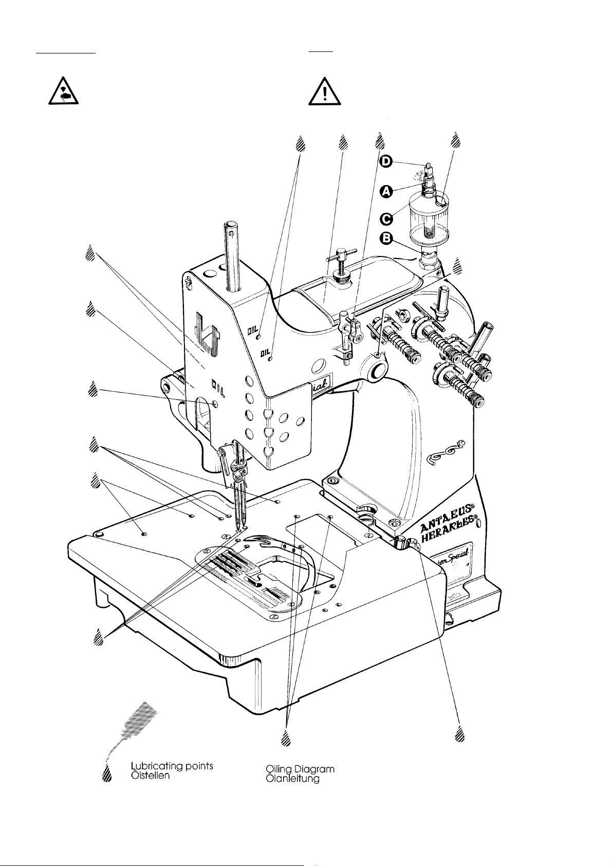
LUBRICATING
ÖLEN
CAUTION!
Turn off main power switch before lubricating!
When using clutch motors with or without
actuation lock wait until motor has completely stopped.
ACHTUNG!
Schalten Sie vor dem Ölen den Hauptschalter aus! Beim Gebrauch von Kupplungsmotoren mit oder ohne Betätigungssperre ist der Stillstand des Motors abzuwarten.
Fig. 1
10
Page 11

LUBRICATING (continued)
ÖLEN (Fortsetzung)
PREPARING FOR OPERATION
Before operating a new machine for the first time,
the sight feed oiler has to be adjusted. All lubricating
points, indicated on the oiling diagram (Fig. 1) have
to be oiled.
For adjusting fill the sight feed oiler halfway with oil
and turn the metering pin (A, Fig. 1) a little bit out and
then turn it in, until there will flow two to three drops of
oil per minute. This can be checked on the sight glass
(B). Secure the setting of the metering pin with lock
nut (C). Fill the oiler.
Repeat the oiling of a new machine after 10 minutes
of operation!
When the machine is out of operation, the oil flow
can be stopped by tilting lever (D) on the sight feed
oiler.
IMPORTANT! The oil flow has to be switched on again
before operating the machine.
For lubrication we recommend "Mobil Oil DTE Medium" or equivalent, which can be purchased from
UNION SPECIAL in 1/2 liter containers under part
number G28604L or in 5 liter containers under part
number G28604L5.
NEEDLES
VORBEREITEN ZUR INBETRIEBNAHME
Bevor eine neue Maschine zum ersten Mal in Betrieb
genommen wird, muß der Tropföler eingestellt werden.
Alle in der Ölanleitung (Fig. 1) angegebenen Ölstellen
müssen geölt werden.
Füllen Sie den Tropföler zum Einstellen halb mit Öl und
drehen Sie den Zumeßstift (A, Fig. 1) etwas aus und dann
so weit ein, bis pro Minute zwei bis drei Tropfen Öl fließen.
Dies kann am Schauglas (B) geprüft werden. Sichern Sie
die Einstellung des Zumeßstiftes mit der Kontermutter (C).
Füllen Sie den Öler.
Wiederholen Sie bei einer neuen Maschine das Ölen
nach einer Betriebsdauer von 10 Minuten!
Wenn die Maschine nicht in Betrieb ist, kann der Ölfluß
durch Umlegen des Hebels (D) am Tropföler gestoppt
werden.
WICHTIG! Der Ölfluß muß
Maschine wieder eingeschaltet werden.
Zum Ölen empfehlen wir "Mobil Oil DTE Medium" oder ein
gleichwertiges Öl, das von UNION SPECIAL in 1/2 Liter
Behältern unter der Teilnummer G28604L oder in 5 Liter
Behältern unter der Teilnummer G28604L5 bezogen
werden kann.
NADELN
vor Inbetriebnahme der
Each needle has both a type and a size number. The
type number denotes the kind of shank, point, length,
groove, finish and other details. The metric size
number, stamped on the needle shank, denotes
largest diameter of blade, measured in hundreds of
a mm midway between shank and eye. Collectively,
the type and size number represent the complete
symbol, which is given on the label of all needles
packaged and sold by UNION SPECIAL.
TYPE AND DESCRIPTION
9853GA Round shank with tapered flat, rounded
square point, single groove, spotted, chromium
plated.
Sizes available: 300/120, 400/156, 430/172.
Standard needle for these machines is 9853GA430/172.
When changing the needle, make sure it is fully
inserted in the needle head with the fastening flat of
the needle shank facing the screw, before the screw
is tightened.
NEEDLE ORDERING
When ordering needles please use the complete type
and size numbers as printed on the package to ensure
prompt and accurate processing of your order.
A complete order should read as follows:
100 needles, type 9853GA430/172.
Jede Nadel hat eine Typ- und eine Dickennummer. Die
Typnummer bezeichnet die Art des Nadelkolbens, der
Spitze, Länge, Rinne, Oberfläche und andere Einzelheiten.
Die Dickennummer, im Nadelkolben eingeprägt, gibt den
größten Durchmesser an, gemessen in hundertstel mm in
der Mitte zwischen Kolben und Öhr. Typnummer und
Dickenbezeichnung zusammen ergeben die vollständige
Nadelbezeichnung, die auf jedem Etikett aller von UNION
SPECIAL gepackten und verkauften Nadeln steht.
TYPNUMMER UND BESCHREIBUNG
9853GA Rundkolben mit konischer Fläche, verrundete
Vierkantspitze, eine Rinne, Hohlkehle, verchromt.
Lieferbare Dicken: 300/120, 400/156, 430/172.
Die Standardnadel für diese Maschinen ist 9853GA430/172.
Stellen Sie beim Nadelwechsel sicher, daß der Nadelkolben
voll im Nadelkopf eingesetzt ist und die Befestigungsfläche
am Nadelkolben gegen die Schraube zeigt, bevor sie
festgezogen wird.
NADELBESTELLUNG
Um Nadelbestellungen richtig und prompt erledigen zu
können, geben Sie bitte die auf der Packung aufgedruckte
komplette Typ- und Dickennummer an.
Eine vollständige Bestellung würde z. B. lauten:
100 Nadeln, Typ 9853GA430/172.
11
Page 12
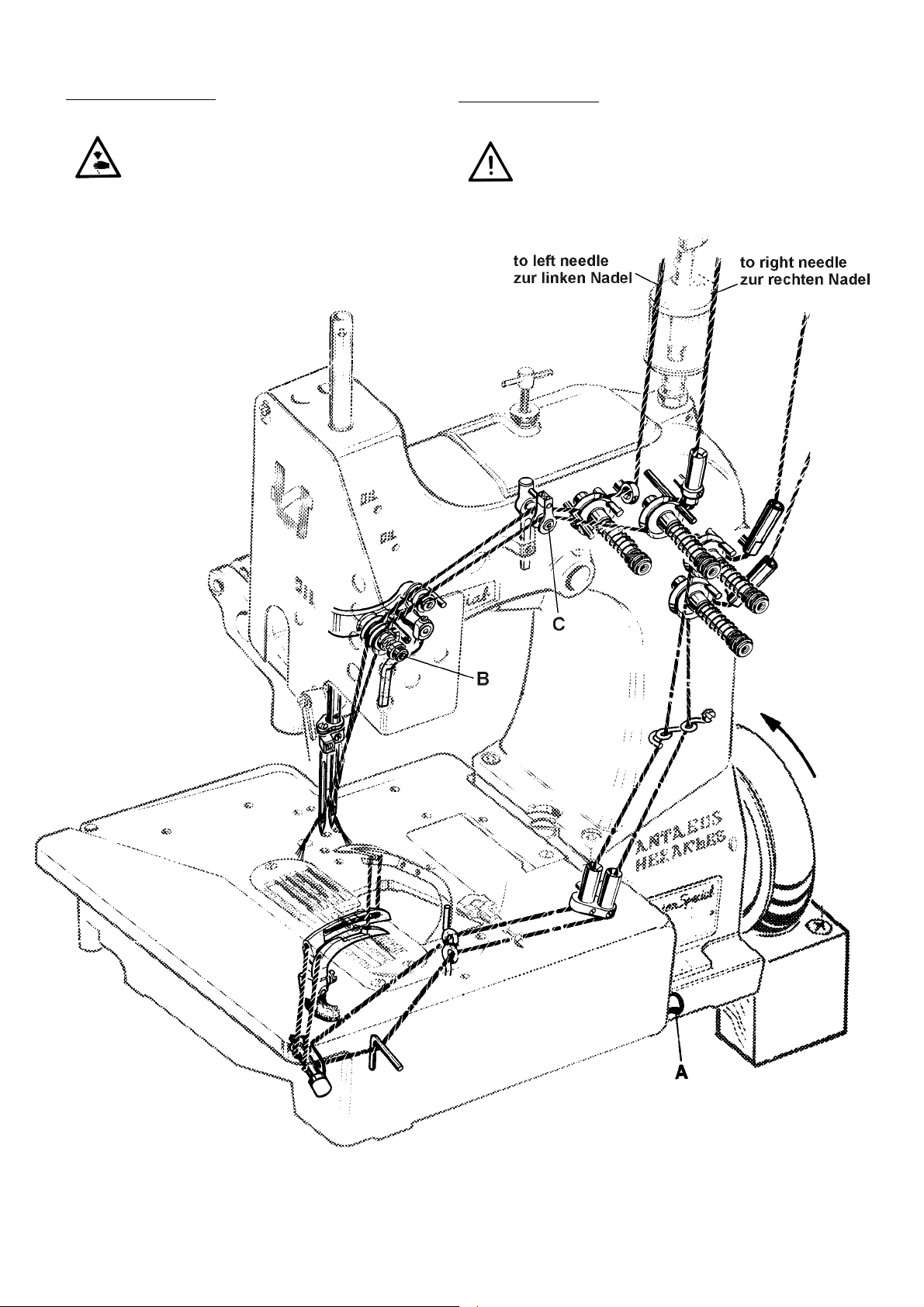
THREADING DIAGRAM
EINFÄDELANLEITUNG
CAUTION! Turn off main power switch before
threading! When using clutch motors with
or without actuation lock wait until the
motor has completely stopped!
ACHTUNG! Schalten Sie vor dem Einfädeln den Haupt-
schalter aus! Warten Sie bei Kupplungsmotoren mit oder ohne Betätigungssperre den
Stillstand des Motors ab!
Fig. 2
12
Page 13
OPERATING INSTRUCTIONS
BEDIENUNGSANLEITUNG
THREADING
81300 series are threaded as shown in Fig. 2.
For threading the needle turn handwheel in operating
direction until the needle is in the upmost position.
For looper threading open the hinge plate by lifting
locking bolt knob (A, Fig. 2).
Reclose hinge plate after threading.
OPERATING
1. Switch on main power switch.
2. Without lifting the presser foot, place the fabric to
be sewn as close as possible in front of the needle
and to the right on the edge guide.
CAUTION! Remove the foot from the motor treadle,
to avoid inadvertently starting of the
machine, in case it is necessary to lift presser
foot and upper feed dog for aligning the
fabric to be sewn!
3. Depress the motor treadle. The machine sews.
Guide the fabric to be sewn.
EINFÄDELN
Die Maschinen 81300 werden, wie in Fig. 2 gezeigt, eingefädelt.
Drehen Sie zum Einfädeln der Nadel das Handrad in
Nährichtung bis die Nadel in ihrer obersten Stellung ist.
Öffnen Sie zum Greifer-Einfädeln die Scharnierplatte durch
Anheben der Griffschraube (A, Fig. 2).
Schließen Sie die Scharnierplatte nach dem Einfädeln wieder.
BEDIENEN
1. Schalten Sie den Hauptschalter ein.
2. Legen Sie das Nähgut, ohne dabei den Drückerfuß
anzuheben, so dicht wie möglich vor die Nadel und
rechts an der Kantenführung an.
ACHTUNG! Nehmen Sie den Fuß vom Motorpedal, da-
mit die Maschine nicht unabsichtlich startet,
wenn es notwendig ist, Drückerfuß und
Obertransporteur zum Ausrichten des
Nähgutes anzuheben!
3. Treten Sie das Motorpedal nach vorne. Die Maschine näht.
Führen Sie das Nähgut.
CAUTION! Keep a security distance of approx. 100 mm
(4") between hand and sewing needle
when guiding the fabric to be sewn!
4. Release the motor treadle. The machine stops.
Cut the thread chain at the trailing edge of the
fabric and remove the fabric from the machine.
MAINTENANCE
CAUTION! Turn off main power switch before doing
maintenance works! When using clutch
motors with or without actuation lock wait
until the motor has stopped!
LUBRICATING AND CLEANING
The machines of class 81300 have to be cleaned and
lubricated twice a day before the morning and
afternoon start on the lubrication points indicated on the
oiling diagram (Fig. 1, page 10). The sight feed oiler has
to be kept filled and should be ajdusted so, that it feeds
two to three drops of oil per minute. The oiler has to be
refilled latest, when 2/3 of the oil are used up (see also
page 11).
ACHTUNG! Halten Sie beim Führen des Nähgutes einen
Sicherheitsabstand von ca. 100 mm zwischen
Hand und Nähnadel ein!
4. Lassen Sie das Motorpedal los. Die Maschine stoppt.
Trennen Sie die Fadenkette am Ende des Nähgutes,
und nehmen Sie das Nähgut von der Maschine.
WARTUNG
ACHTUNG! Schalten Sie vor Wartungsarbeiten den Haupt-
schalter aus! Warten Sie bei Kupplungsmotoren mit oder ohne Betätigungssperre den Stillstand des Motors ab!
ÖLEN UND REINIGEN
Die Maschinen der Klasse 81300 müssen zweimal täglich,
vor der Inbetriebnahme am Morgen und Nachmittag,
gereinigt und an den in der Ölanleitung (Fig. 1, Seite 10)
angegebenen Stellen geölt werden. Der Topföler muß
gefüllt und so eingestellt sein, daß pro Minute zwei bis drei
Tropfen Öl fließen. Der Öler muß spätestens nachgefüllt
werden, wenn 2/3 der Ölmenge verbraucht sind (siehe
auch Seite 11).
13
Page 14
INDSTRUCTIONS FOR MECHANICS
MECHANIKERANLEITUNG
HINT: The right needle forms along with the left lower
looper at the rear, the right upper spreader with
thread hook and the thread retainer the overedge
stitch type 502 (HERAKLES).
The left needle forms along with the left lower looper
at the front and the upper cross looper the double
locked stitch type 401 (ANTAEUS).
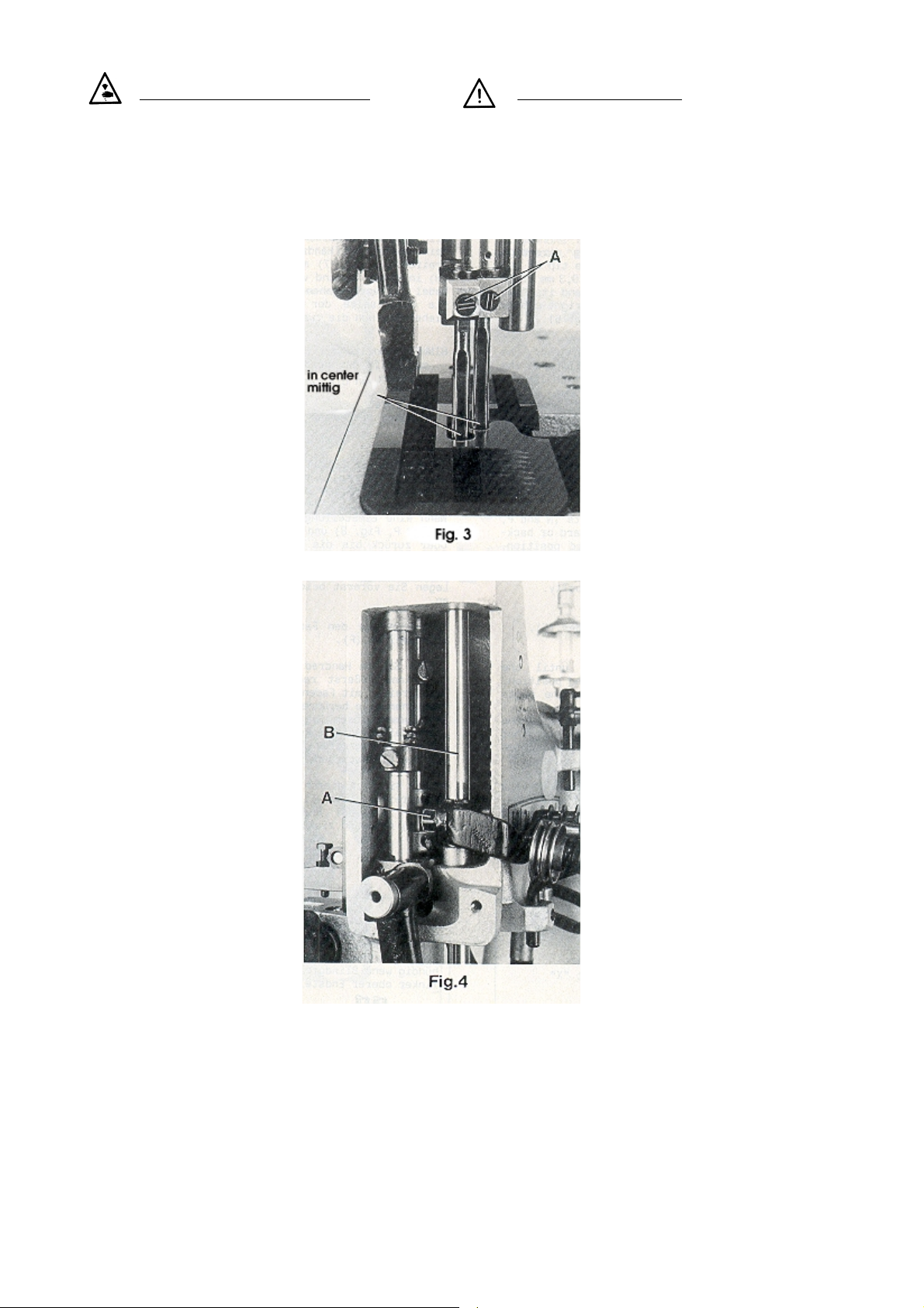
INSERTING THE NEEDLES
Before adjusting the machine
insert a new set of needles with
the shank as far as possible into
the needle holder. The long
groove of the needles must
point to the front (towards the
operator). Tighten the set
screws (A, Fig. 3) on the tapered
fastening flats of the needle
shanks.
ALIGNING THE NEEDLE BAR
Remove the face cover and
the finger guard left on the
machine head as well as the
upper feed dog and the presser
foot. Rotate handwheel in
operating direction and check
if the needles center in the
associated needle holes of the
throat plate (see Fig. 3). If not
loosen clamp screw (A, Fig. 4)
in the needle bar connection
and turn the needle bar (B)
accordingly. Retighten screw
(A.).
HINT: For aligning the needle
bar test plate No. 040 37006
0000 can be used in lieu of the
throat plate. The test plate is an
extra order and charge item.
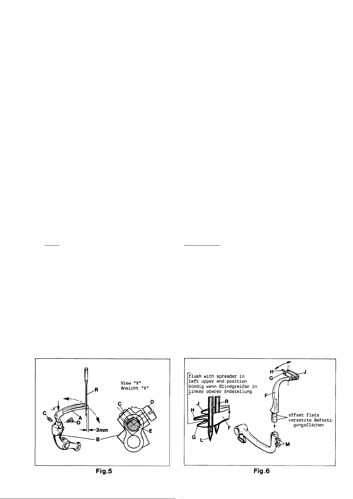
SETTING THE LOWER LOOPER
FOR THE OVEREDGE STITCH
Remove the cloth plate with
hinge plate and throat plate,
the feed dog, the throat plate
support and the needle guard.
Insert the lower looper (A, Fig.
5) into the rear hole of the
looper lever (B). Now snug the
set screw (C) at the back of the
looper lever against the flat on
the looper shank (E) so that the
lower looper point passes as
close as possible to the spot on
the back of the right needle
(R), without deflecting it. Now
tighten the second screw (D)
firmly.
SETTING HEIGHT OF NEEDLE BAR
Rotate handwheel in operating direction until the
point of lower looper (A, Fig. 5) projects 3 mm (1/8") to
the right from the right side of the right needle. Lower
edge of looper and upper edge of needle eye must
be flush in this position.
If an adjustment is necessary loosen clamp screw (A,
Fig. 4) in the needle bar connection and move the
needle bar (B) up or down, as required. Care should
be taken not to disturb the alignment of the needle
bar when making this adjustment. Retighten clamp
screw.
HINWEIS: Die rechte Nadel bildet zusammen mit dem
Untergreifer links hinten, dem rechten oberen Blindgreifer
mit Fadenhaken und dem Fadenholer den Überwendlichstich, Typ 502 (HERAKLES).
Die linke Nadel bildet zusammen mit dem Untergreifer
links vorne und dem oberen Quergreifer den
Doppelkettenstich, Type 401 (ANTAEUS).
EINSETZEN DER NADELN
Setzen Sie vor dem Einstellen der
Maschine einen Satz neuer Nadeln so
ein, daß der Nadelkolben oben im
Nadelhalter anstößt und die lange
Rinne der Nadeln nach vorne (zur
Bedienungsperson) zeigt. Ziehen Sie
die Gewindestifte (A, Fig. 3) auf der
konischen Befestigungsfläche am
Nadelkolben fest.
AUSRICHTEN DER NADELSTANGE
Entfernen Sie den Abschlußdeckel
und den Fingerschutz links am Maschinenkopf, sowie den Obertransporteur
und den Drückerfuß. Drehen Sie das
Handrad in Nährichtung und prüfen
Sie, ob die Nadeln mittig in die zugehörigen Stichlöcher der Stichplatte
einstechen (siehe Fig. 3). Wenn nicht,
lösen Sie die Klemmschraube (A, Fig.
4) im Nadelstangenmitnehmer und
drehen die Nadelstange (B) entsprechend. Ziehen Sie die Schraube (A)
wieder an.
HINWEIS: Zum Ausrichten der Nadelstange kann anstelle der Stichplatte
die Testplatte Nr. 040 37006 0000
verwendet werden. Die Testplatte ist
gegen zusätzliche Bestellung und
Berechnung lieferbar.
EINSTELLUNG DES UNTERGREIFERS FÜR
DEN ÜBERWENDLICHSTICH
Entfernen Sie die Stoffplatte mit
Scharnierplatte und Stichplatte, den
Transporteur, die Stichplattenstütze
und den Nadelanschlag. Stecken Sie
den Untergreifer (A, Fig. 5) in die
hintere Bohrung des Greiferhebels (B).
Legen Sie nun den Gewindestift (C)
hinten im Greiferhebel an der Fläche
des Greiferschaftes (E) so an, daß die
Untergreiferspitze so dicht wie möglich
in der Hohlkehle auf der Rückseite der
rechten Nadel (R) vorbeigeht, ohne
diese abzulenken. Ziehen Sie dann
die zweite Schraube (D) gut an.
EINSTELLUNG DER NADELSTANGENHÖHE
Drehen Sie das Handrad in Nährichtung bis die Spitze des
Untergreifers (A, Fig. 5) 3 mm rechts von der rechten Seite
der rechten Nadel steht. In dieser Stellung müssen Unterkante Greifer und Oberkante Nadelöhr bündig sein.
Ist eine Einstellung notwendig, lösen Sie die Klemmschraube
(A, Fig. 4) im Nadelstangenmitnehmer und schieben Sie
die Nadelstange (B) entsprechend nach oben oder unten.
Beachten Sie, daß bei dieser Einstellung die Ausrichtung
der Nadelstange nicht verändert wird. Ziehen Sie die
Klemmschraube wieder an.
14
Page 15
SETTING THE RIGHT UPPER SPREADER FOR THE
OVEREDGE STITCH
EINSTELLUNG DES RECHTEN OBEREN BLINDGREIFERS FÜR
DEN ÜBERWENDLICHSTICH
Before inserting a new spreader (F, Fig. 6) remove
thread hook (J). This facilitates the visual check of the
adjustment.
For adjustment of spreader (F, Figs. 6 and 7) with
respect to the needles (L and R), the shank of spreader
(F) has two offset flats.
Proceed as follows:
First snug one screw (M, Fig. 6) on the flat of the
spreader shank which obtains the following position
of the spreader:
When rotating the handwheel in operating direction
spreader (F, Fig. 7) should pass with the tip of its upper
prong (H) in a distance of 0.25 to 0.3 mm (.010 to .012")
behind the left needle (L) and its face (K) should not
contact the front of the right needle (R). Now tighten
the second screw (M, Fig. 6).
HINT: In case the adjusting possibility of the spreader
by means of the two offset flats on the spreader shank
is not sufficient, additionally the complete spreader
shaft bearing (S, Fig. 8) can be moved slightly up or
down when loosening screws (R). Retighten screws.
In the extreme left upper end position of spreader (F,
Fig. 6), the bottom of the cutout between the two
looper prongs (G and H) should be flush with the left
side of the left needle (L).
If an adjustment is necessary, loosen nuts (N and P,
Fig. 8) and turn connecting rod (Q) forward or
backward as required to obtain the required position.
NOTE: The left nut (P) has a left hand thread.
Temporarily snug the two nuts (N and P)
manually.
Bevor Sie einen neuen Blindgreifer (F, Fig. 6) einsetzen,
entfernen Sie den Fadenhaken (J). Dies erleichtert die
visuelle Prüfung der Einstellung.
Zum Einstellen des Blindgreifers (F, Fig. 6 und 7) in Bezug zu
den Nadeln (L und R) hat der Schaft des Blindgreifers (F)
zwei versetzte Befestigungsflächen.
Gehen Sie wie folgt vor:
Legen Sie zuerst eine Schraube (M, Fig. 6) auf der Fläche
des Blindgreifers an, mit der Sie folgende Stellung des
Blindgreifers erhalten:
Beim Drehen des Handrades in Nährichtung muß der
Blindgreifer (F, Fig. 7) mit der Spitze seines oberen Zinkens
(H) in einem Abstand von 0,25 bis 0,3 mm hinter der linken
Nadel (L) vorbeigehen und darf mit seiner Stirnfläche (K)
die Vorderseite der rechten Nadel (R) nicht berühren.
Ziehen Sie nun die zweite Schraube (M, Fig. 6) an.
HINWEIS: Sollte die Einstellmöglichkeit des Blindgreifers mit
Hilfe der beiden versetzten Befestigungsflächen am
Greiferschaft nicht ausreichen, kann nach Lösen der
beiden Schrauben (R, Fig. 8) zusätzlich das ganze Greiferachslager (S) etwas nach oben oder unten verschoben
werden. Ziehen Sie die beiden Schrauben wieder an.
In der äußerst linken oberen Endstellung des Blindgreifers
(F, Fig. 6) soll die tiefste Stelle des Einschnittes zwischen den
beiden Greiferzinken (G und H) mit der linken Seite der
linken Nadel (L) bündig sein.
Wenn eine Einstellung notwendig ist, lösen Sie die Muttern
(N und P, Fig. 8) und drehen die Verbindungsstange (Q)
vor oder zurück bis die erforderliche Stellung erreicht ist.
BEACHTEN SIE: Die linke Mutter (P) hat ein
Linksgewinde. Legen Sie vorerst beide
Muttern (N und P) von Hand leicht an.
Remount thread hook (J, Fig. 6) on spreader (F).
Rotate handwheel in operating direction until the
spreader is in its extreme right lower end position. The
spreader should not contact any machine parts
during its motion.
If required loosen clamp screw (U, Fig. 10) in the
spreader drive lever (V) and set the lever so that the
spreader (F) clears at all points. Retighten clamp
screw.
After this setting recheck the position of the spreader
to the left needle, as described above. Reset with
connecting rod (Q, Fig. 8) if required and tighten nuts
(N and P).
Montieren Sie den Fadenhaken (J, Fig. 6) wieder an den
Blindgreifer (F).
Drehen Sie das Handrad in Nährichtung bis der Blindgreifer
in seiner äußerst rechten unteren Endstellung ist. Der
Blindgreifer mit Fadenhaken darf bei seiner Bewegung
keine Maschinenteile berühren.
Bei Bedarf lösen Sie die Klemmschraube (U, Fig. 10) im
Blindgreifer-Antriebshebel (V) und stellen den Hebel so,
daß der Blindgreifer (F) an allen Stellen freigeht. Ziehen Sie
die Klemmschrauben wieder an.
Prüfen Sie nach dieser Einstellung nochmals die Stellung
des Blindgreifers zur linken Nadel, wie oben beschrieben.
Stellen Sie bei Bedarf mit der Verbindungsstange (Q, Fig.
8) nach und ziehen Sie die Muttern (N und P) an.
15
Page 16

SETTING THE RIGHT UPPER SPREADER FOR THE OVEREDGE
STITCH (continued)
EINSTELLUNG DES RECHTEN OBEREN BLINDGREIFERS FÜR DEN
ÜBERWENDLICHSTICH (Fortsetzung)
Rotate handwheel in operating direction. On the
upward travel of spreader (F, Fig. 9) the tip of its lower
prong (G) must pass as close as possible in the recess
behind the eye of the lower looper (A) without
contacting it.
If an adjustment is required, loosen nut (T, Fig. 8) on
the double joint and swing the lower looper lever with
lower looper accordingly to the right or left. Retighten
nut (T).
NOTE: Check the setting of the needle bar
height after making this adjustment and
reset if required. Refer to paragraph
"SETTING HEIGHT OF NEEDLE BAR".
Drehen Sie dasHandrad in Nährichtung. Bei der Bewegung
des Blindgreifers (F, Fig. 9) nach oben muß die Spitze seines
unteren Zinkens (G) so dicht wie möglich in der Aussparung
hinter dem Öhr des Untergreifers (A) vorbeigehen, ohne
diesen zu berühren.
Ist eine Einstellung notwendig, lösen Sie die Mutter (T, Fig. 8)
am Doppelgelenk und schwenken Sie den Untergreiferhebel mit dem Untergreifer entsprechend nach
rechts oder links. Ziehen Sie die Mutter (T) wieder an.
BEACHTEN SIE: Prüfen Sie nach dieser Einstellung die
Nadelstangenhöhe und stellen Sie bei
Bedarf nach. Siehe Absatz "EINSTELLUNG
DER NADELSTANGENHÖHE".
SETTING THE THREAD RETAINER FOR THE OVEREDGE
STITCH
Viewed from the left end of the machine the thread
retainer (B, Fig. 11) should pass as close as possible on
the left side of lower looper (A) when swinging upward
without contacting it.
On the most upward position of its swing motion the
thread retainer (B) should not interfere neither with the
bottom of the throat plate nor with the feed dog.
EINSTELLUNG DES FADENHOLERS FÜR DEN ÜBERWENDLICHSTICH
Vom linken Ende der Maschine aus gesehen soll der
Fadenholer (B, Fig. 11) beim Schwenken nach oben so
dicht wie möglich an der linken Seite des Untergreifers (A)
vorbeigehen, ohne diesen zu berühren.
Am höchsten Punkt seiner Schwenkbewegung darf der
Fadenholer (B) weder die Unterseite der Stichplatte noch
den Transporteur berühren.
16
Page 17
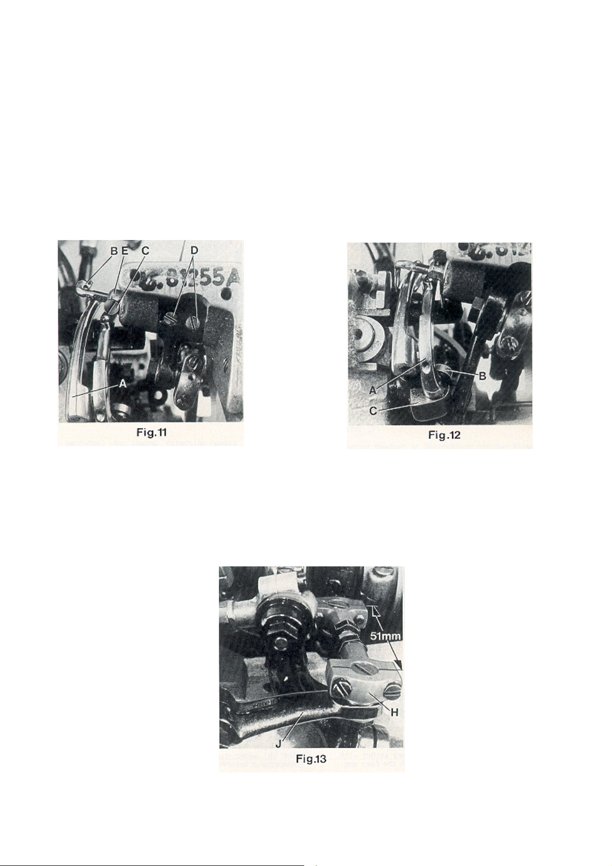
SETTING THE THREAD RETAINER FOR THE OVEREDGE
STITCH (continued)
After loosening screw (C, Fig. 11) the thread retainer
(B) can be moved to the left or right. Retighten screw
on the flat of the thread retainer shank.
After loosening the two set screws (D), shaft (E) with
the thread retainer (B) can be rotated into the correct
position. Make sure to remove all lateral end play
when tightening the set screws.
EINSTELLUNG DES FADENHOLERS FÜR DEN ÜBERWENDLICHSTICH (Fortsetzung)
Nach Lösen der Schraube (C, Fig. 11) kann der Fadenholer
(B) nach links oder rechts verschoben werden. Ziehen Sie
die Schraube wieder auf der Befestigungsfläche des
Fadenholerschaftes an.
Nach Lösen der beiden Gewindestifte (D) kann die Achse
(E) mit dem Fadenholer (B) in die richtige Stellung gedreht
werden. Achten Sie beim Anziehen der Gewindestifte
darauf, daß kein seitliches Spiel vorhanden ist.
SETTING THE DOUBLE LOCKED STITCH LOOPER
Insert the double locked stitch looper (A, Fig. 12) and
tighten it with screw (B) on the flat of its shank so that
it passes as close as possible behind the left needle
without touching it. Now tighten set screw (C).
SETTING THE CROSS LOOPER FOR DOUBLE LOCKED STITCH
EINSTELLUNG DES DOPPELKETTENSTICHGREIFERS
Setzen Sie den Doppelkettenstichgreifer (A, Fig. 12) ein
und ziehen Sie ihn mit der Schraube (B) auf der Befestigungsfläche seines Schaftes so fest, daß er so dicht wie
möglich hinter der linken Nadel vorbeigeht, ohne diese zu
berühren. Ziehen Sie nun den Gewindestift (C) an.
EINSTELLUNG DES QUERGREIFERS FÜR DOPPELKETTENSTICH
The distance (set at the factory) from center to center
of the two ball joints driving the cross looper should be
51 mm (2") (see Fig. 13).
Basically the front ball joint (H, Fig. 13) should be
positioned as far as it will go to the left in the fastening
slot of the cross looper drive lever (J).
When rotating the handwheel in
operating direction cross looper
(D, Fig. 14) should swing as close
as possible in the recess behind
the eye over the double locked
stitch looper (A) without
contacting it.
At the left end of its swing motion
cross looper (D, Fig. 15) must be
positioned so that the left needle
(L) securely stitches into the
thread loop hanging around the
hook of cross looper (D). In front
of the left needle the cross looper
should pass in a distance of 0.3
mm (.012") (see Fig. 15).
Check this as follows:
Hang a piece of thread around
the hook of the cross looper and
draw it slightly in sewing direction.
Now rotate handwheel in sewing
direction. The left needle must
enter securely between the two
thread ends.
Der Abstand (im Werk eingestellt) von Mitte zu Mitte zwischen den beiden Kugelgelenken zum Antrieb des Quergreifers muß 51 mm betragen (siehe Fig. 13).
Standardmäßig soll das vordere Kugelgelenk (H, Fig. 13) so
weit wie möglich nach links im Befestigungslangloch des
Quergreifer-Antriebhebels (J) gestellt werden.
Beim Drehen des Handrades in
Nährichtung soll der Quergreifer
(D, Fig. 14) so dicht wie möglich in
der Aussparung hinter dem Öhr
über den Doppelkettenstichgreifer (A) schwenken, ohne diesen
zu berühren.
Am linken Ende seiner Schwenkbewegung muß der Quergreifer
(D, Fig. 15) so stehen, daß die linke
Nadel (L) sicher in die um den
Haken des Quergreifers (D) hängende Fadenschleife einsticht.
Vor der linken Nadel soll der Quergreifer in einem Abstand von 0,3
mm vorbeischwenken (siehe Fig.
15).
Prüfen Sie dies wie folgt:
Hängen Sie einen Faden um den
Haken des Quergreifers und
ziehen ihn leicht in Nährichtung.
Nun drehen Sie am Handrad in
Nährichtung; die linke Nadel muß
sicher zwischen den beiden Fa-
17
denenden einstechen.
Page 18

SETTING THE CROSS LOOPER FOR DOUBLE LOCKED
STITCH (continued)
After loosening the two screws (E, Fig. 15) the 0.3 mm
(.012") distance to the left needle is adjustable.
Retighten screws on the flat of the cross looper shank.
After loosening clamp screw (G. Fig. 14) cross looper
lever (F) can be raised or lowered for setting the height
of cross looper (D) with respect to the double locked
stitch looper (A) and it can be tilted to the right or left
for adjusting the swing motion of the cross looper with
respect to the left needle. Retighten clamp screw.
If required the length of the path of the cross looper
swing motion can be reduced by positioning ball joint
(H, Fig. 13) to the right in the fastening slot of the cross
looper drive lever (J).
Make sure when setting the cross looper that it does
not interfere with the bottom of the throat plate or
other machine parts.
EINSTELLUNG DES QUERGREIFERS FÜR DOPPELKETTENSTICH
(Fortsetzung)
Nach Lösen der beiden Schrauben (E, Fig. 15) kann der 0,3
mm Abstand zur linken Nadel eingestellt werden. Ziehen
Sie die Schrauben wieder auf der Befestigungsfläche des
Quergreiferschaftes fest.Nach Lösen der Klemmschraube
(G, Fig. 14) kann der Quergreiferhebel (F) nach oben oder
unten verschoben werden, um die Höhe des Quergreifers
(D) zum Doppelkettenstichgreifer (A) einzustellen und nach
rechts oder links geschwenkt werden, um die Schwenkbewegung des Quergreifers in Bezug zur linken Nadel
einzustellen. Ziehen Sie die Klemmschraube wieder fest.Bei
Bedarf kann der Schwenkweg des Quergreifers durch
Versetzen des Kugelgelenks (H, Fig. 13) im Befestigungslangloch des Quergreifer-Antriebhebels (J) nach rechts
verkleinert werden.
Achten Sie beim Einstellen des Quergreifers darauf, daß er
weder die Unterseite der Stichplatte noch andere Maschinenteile berührt.
SETTING THE NEEDLE GUARD
When the needle guard (A, Fig. 16) is in its most forward
end position, its guarding surfaces should just contact
the back of the needles without deflecting them.
After loosening screw (B, Fig. 16) needle guard (A) can
be moved accordingly to the front or to the rear.
Retighten screw.
NOTE: Any change in stitch length necessitates a
corresponding change in the needle guard
setting.
EINSTELLUNG DES NADELANSCHLAGS
Wenn der Nadelanschlag (A, Fig. 16) in seiner vorderen
Endstellung ist, sollen seine Schutzflächen die Rückseite
der Nadeln gerade berühren, ohne sie abzulenken.
Nach Lösen der Schraube (B, Fig. 16) kann der Nadelanschlag (A) entsprechend nach vorne oder hinten
geschoben werden. Ziehen Sie die Schraube wieder an.
BEACHTEN SIE: Jede Änderung der Stichlänge erfordert
ein entsprechendes Nachstellen des
Nadelanschlags!
18
Page 19

SETTING THE LOWER FEED DOG
The lower feed dog (A, Fig. 17)
should center laterally in the
slots of throat plate (B).
If an adjustment is necessary
loosen the two set screws (C,
Fig. 18) and move feed rocker
(D) to the left or right as
required. Retighten set screws.
At highest point of feed travel
the rear teeth of the feed dog
(A, Fig. 19) should just project
their full depth above the top
surface of throat plate.
Adjust the supporting screw
(E, Fig. 16) in the feed bar to
the required height and
assemble the feed dog.
THROAT PLATE SUPPORT
Assemble the throat plate support (A, Fig. 20) with
screws (B) so that it does not interfere with the feed
dog or any other machine parts.
EINSTELLUNG DES UNTEREN TRANSPORTEURS
Der untere Transporteur (A, Fig. 17)
muß in den Schlitzen der Stichplatte
(B) seitlich vermittelt sein.
Ist eine Einstellung notwendig, lösen
Sie die Gewindestifte (C, Fig. 18) und
schieben Sie den Transportantriebsrahmen (D) nach Bedarf nach links
oder rechts. Ziehen Sie die Gewindestifte wieder an.
Im höchsten Punkt der Transportbewegung sollen die hinteren Zähne
des Transporteurs (A, Fig. 19) gerade
eine Zahnhöhe über die Stichplattenoberfläche ragen.
Stellen Sie die Stützschraube (E, Fig.
16) im Transporteurträger auf die entsprechende Höhe und montieren Sie
den Transporteur.
STICHPLATTENSTÜTZE
Montieren Sie die Stichplattenstütze (A, Fig. 20) mit den
Schrauben (B) so, daß sie weder den Transporteur noch
andere Maschinenteile berührt.
SETTING THE UPPER FEED DOG
Assemble the upper feed dog (B, Fig. 21) and the
presser foot (C). The upper feed dog (B) should not
push against the front or rear end when moving in
the slots of presser foot (C).
Simultaneously the upper feed
dog (B, Fig. 19) should be
positioned so that the tips of its
teeth engage with the tooth
spaces of the lower feed dog
(A), without contacting it. When
the lower feed dog (A) is in its
highest and the upper feed dog
(B) in its lowest point of travel,
there must be a small gap
between both feed dogs.
The feed travel of the upper
and the lower feed dog should
be synchronous.
For setting the upper feed dog
with respect to the slot ends in
the presser foot and the tooth
spaces of the lower feed dog,
loosen screw (D, Fig. 21) and
turn drive lever (E) accordingly
to the front or rear. Retighten
screw.
EINSTELLUNG DES OBEREN TRANSPORTEURS
Montieren Sie den Obertransporteur (B, Fig. 21) und den
Drückerfuß (C). Der Obertransporteur (B) darf bei seiner
Bewegung in den Schlitzen im Drückerfuß (C) weder vorne
noch hinten anstoßen.
Gleichzeitig muß der Obertransporteur (B, Fig. 19) so positioniert
sein, daß die Spitzen seiner Zähne in
die Zahnlücken des unteren Transporteurs (A) eingreifen, ohne diesen
zu berühren. Wenn der untere Transporteur (A) in der höchsten und der
Obertransporteur (B) in der untersten
Stellung seiner Bewegung ist, muß
zwischen beiden Transporteuren ein
Luftspalt sein. Die Transportwege
des oberen und unteren Transporteurs müssen gleich (synchron)
sein.
Zum Einstellen des Obertransporteurs in Bezug zu den Schlitzenden
im Drückerfuß und zu den Zahnlücken des unteren Transporteurs
lösen Sie die Schraube (D, Fig. 21)
und schwenken Sie den Antriebshebel (E) entsprechend nach vorn
oder hinten. Ziehen Sie die Schraube
wieder an.
19
Page 20

SETTING THE UPPER FEED DOG (continued)
For setting the small gap between the feed dogs
loosen nut (F, Fig. 22). Turning in screw (G) increases
the gap, turning it out decreases the gap. Retighten
nut (F).
For matching the upper feed dog travel with the
lower feed dog travel loosen screw (A, Fig. 23).
Moving the ball link in the slot of rocker lever (B) to
the front decreases the upper feed dog travel,
moving it to the rear increases the travel. Retighten
screw (A).
EINSTELLUNG DES OBEREN TRANSPORTEURS (Fortsetzung)
Zum Einstellen des Luftspalts zwischen den Transporteuren
lösen Sie die Mutter (F, Fig. 22). Eindrehen der Schraube
(G) vergrößert den Luftspalt, Herausdrehen verkleinert
ihn. Ziehen Sie die Mutter (F) wieder an.
Zum Angleichen des Obertransportwegs an den Weg des
unteren Transporteurs lösen Sie die Schraube (A, Fig. 23).
Verschieben des Kugelgelenks im Kulissenhebel (B) nach
vorne verkleinert den Transportweg, Verschieben nach
hinten vergrößert ihn. Ziehen Sie die Schraube (A) wieder
an.
SETTING THE LIFT MOTION OF THE UPPER FEED DOG
On the return travel, the upper feed dog should lift
so high that no fabric will be pulled against the
sewing direction.
The motion should be set so that the rear four teeth
of the upper feed dog (B, Fig. 21) remain approx.
1/3 of their height in the presser foot slots when
lifting.
For adjustment loosen the two screws (H, Fig. 22)
and raise the supporting yoke (J) when the upper
feed dog should lift more, or lower it when it should
lift less. Retighten screws (H).
EINSTELLUNG DER ABHEBBEWEGUNG DES OBERTRANSPORTEURS
Beim Rückweg muß der Obertransporteur so hoch abheben, daß kein Nähgut entgegen der Nährichtung gezogen wird.
Die Bewegung muß so eingestellt sein, daß die hinteren
vier Zähne des Obertransporteurs (B, Fig. 21) beim Abheben
noch mit etwa 1/3 ihrer Höhe in den Drückerfußschlitzen
sind.
Zum Einstellen lösen Sie die beiden Schrauben (H, Fig. 22)
und stellen das Stützlager (J) höher, wenn der Obertransporteur mehr oder tiefer, wenn er weniger abheben
soll. Ziehen Sie die Schrauben (H) wieder an.
PRESSER FOOT PRESSURE ON 81300A, AJ, B
Rotate handwheel until the lower feed dog is
below the throat plate. Loosen knurled nut (A. Fig.
24) and turn out T-screw (B) until it does not excert
any pressure on the leaf springs. In this position, the
pressure excerted on the presser foot should be so
strong that the presser foot bottom and the front
end of the presser foot tongue rest squarly on the
throat plate.
DRÜCKERFUSSDRUCK BEI 81300A, AJ, B
Drehen Sie das Handrad bis der untere Transporteur unter
der Stichplatte steht. Lösen Sie die Rändelmutter (A, Fig.
24) und drehen Sie die Knebelschraube (B) soweit heraus,
daß sie nicht mehr auf die Blattfedern drückt. In dieser
Stellung soll der Druck auf den Drückerfuß so stark sein,
daß die Drückerfußsohle und das vordere Ende der
Drückerfußzunge flach auf der Stichplatte aufliegen.
20
Page 21

PRESSER FOOT PRESSURE (contiued)
By relocating the collars (C, Fig. 25) which serve as a
leaf spring rest on the left and right presser bar, the
pressure can be changed. Raising the collars increases the pressure, lowering the collars decreases it.
The presser foot lift is limited with the upper stop collar
(D, Fig. 25) on the right presser bar. When the needles
are in their lowest position and the presser foot is
lifted with the presser foot lifter lever, the needle
holder should not contact the presser foot. Besides
this, the lifted presser foot should not contact the
right upper spreader moving upwards. Set the stop
collar (D) accordingly.
Make sure that both presser bars move up and down
freely without binding.
Now turn in T-screw (B, Fig. 24) until the necessary
presser foot pressure for proper feeding is excerted
(determine by sewing tests). Secure this setting with
the knurled nut (A), which simultaneously fastens the
upper arm cover. Remount the face cover and the
finger guard.
DRÜCKERFUSSDRUCK (Fortsetzung)
Durch Verstellen der als Blattfederauflage dienenden Stellringe
(C, Fig. 25) auf der linken und rechten Drückerfußstange kann
der Druck verändert werden. Verstellen der Stellringe nach
oben verstärkt, Verstellen nach unten verringert den Druck.
Der Hub des Drückerfußes wird mit dem Anschlag-Stellring (D,
Fig. 25) oben auf der rechten Drückerfußstange begrenzt.
Wenn die Nadeln in der untersten Stellung sind und der
Drückerfuß mit dem Drückerfuß-Lifterhebel angehoben wird,
darf der Nadelhalter den Drückerfuß nicht berühren. Zudem
darf der geliftete Drückerfuß den nach oben gehenden
rechten oberen Blindgreifer nicht berühren. Stellen Sie den
Anschlag-Stellring (D) entsprechend ein.
Überzeugen Sie sich, daß sich beide Drückerfußstangen, ohne
zu klemmen, auf- und abbewegen.
Nun drehen Sie die Knebelschraube (B, Fig. 24) soweit ein, daß
der zum einwandfreien Transport notwendige Drückerfußdruck
erzeugt wird (durch Nähversuche ermitteln). Sichern Sie diese
Einstellung mit der Rändelmutter (A), mit der gleichzeitig der
obere Armdeckel befestigt wird. Montieren Sie den Stirndeckel
und den Fingerschutz wieder.
EDGE GUIDE AND STITCH TONGUE
Set the edge guide (A, Fig. 26) laterally as close as
possible to the presser foot without contacting it.
When loosening the two screws (B), the edge guide
(A) can be moved laterally. Retighten screws.
Set the stitch tongue (C, Fig. 26) so that the rear part
of the thread loop slides over the tongue onto the
fabric, while the front part of the loop is retained until
the right needle securely has entered the loop. After
loosening screw (D) the stitch tongue (C) can be
moved to the front or to the rear. When moving the
sitch tongue to the rear, the front part of the thread
loop is retained longer. Retighten screws (D).
On its travel the upper spreader (E, Fig. 26) should not
contact stitch tongue (C).
CHANGING STITCH LENGTH
The length of the stitch can be adjusted by raising or
lowering stud (A, Fig. 27) in the segment slot of feed
rocker (C) located at the rear of machine below the
cloth plate. Lowering stud (A) will lengthen the stitch,
raising the stud will shorten the stitch. After loosening
nut (B), stud (A) can be moved accordingly. When
the desired stitch length is obtained, retighten nut
(B).
NOTE: Any change in stitch length necessitates a
corresponding change in the needle guard
setting and matching of the upper feed dog
travel!
KANTENFÜHRUNG UND STICHZUNGE
Stellen Sie die Kantenführung (A, Fig. 26) seitlich so dicht wie
möglich an den Drückerfuß, ohne diesen zu berühren. Nach
Lösen der beiden Schrauben (B) kann die Kantenführung (A)
seitlich verschoben werden. Ziehen Sie die Schrauben wieder
an.
Stellen Sie die Stichzunge (C, Fig. 26) so, daß der hintere Teil
der Fadenschlinge über die Zunge auf das Nähgut gleitet,
während der vordere Teil der Schlinge so lange zurückgehalten
wird, bis die rechte Nadel sicher in die Schlinge eingestochen
hat. Nach Lösen der Schrauben (D) kann die Stichzunge (C)
nach vorne oder hinten verschoben werden. Wird die
Stichzunge nach hinten verschoben, wird der vordere Teil der
Fadenschlinge länger zurückgehalten. Ziehen Sie die
Schrauben (D) wieder an.
Der obere Blindgreifer (E, Fig. 26) darf bei seiner Bewegung die
Stichzunge nicht berühren.
ÄNDERN DER STICHLÄNGE
Die Stichlänge kann durch Höher- oder Tieferstellen des Bolzens
(A, Fig. 27) in der Nut des Transportantriebsrahmens (C) hinten
an der Maschine unter der Stoffplatte verändert werden.
Tieferstellen des Bolzens (A) verlängert den Stich, Höherstellen
verkürzt ihn. Nach Lösen der Mutter (B) läßt sich der Bolzen (A)
entsprechend verschieben. Wenn die gewünschte Stichlänge
eingestellt ist, ziehen Sie die Mutter (B) wieder an.
BEACHTEN SIE: Bei jeder Änderung der Stichlänge muß der
Nadelanschlag entsprechend nachgestellt
und der Obertransportweg angeglichen
werden!
21
Page 22

NEEDLE THREAD TAKE-UP AND THREAD TENSIONS
NADELFADENABZUG UND FADENSPANNUNGEN
Basically the needle thread take-up roller (B, Fig. 2),
located left on the upper bed casting under the face
cover, is set as low as possible.
In case more needle thread should be pulled off
(depending on thread and fabric), raise the needle
thread take-up roller accordingly.
Fasten the needle thread roller guide (C, Fig. 2), located
on the top of the upper bed casting, approx. in the
middle of its shank.
The tension applied on the needle threads should be
fairly strong to produce uniform stitches.
Set the collar for the needle thread tension on the up
and down moving needle bar connection so that its
front face is flush with the face of the tension post.
The tension applied to the double locked stitch looper
thread (stitch type 401) should be very slight and just
sufficient to steady the thread.
The tension applied to the overedge stitch looper
thread (stitch type 502) should be slightly higher than
the tension applied to the double locked stitch looper
thread.
SETTING THE TIME RELAYS IN THE SWITCH BOX OF HOT
THREAD CHAIN CUTTER
Styles 81300A1H, B1H
The switch box includes two time relays marked K2T
and K4T.
Standardmäßig wird die Nadelfadenabzugs-Rollenführung (B,
Fig. 2) links am Gehäuseoberteil unter dem Stirndeckel so tief
wie möglich gestellt.
Soll mehr Nadelfaden abgezogen werden (abhängig von
Faden und Nähgut), stellen Sie die NadelfadenabzugsRollenführung entsprechend höher.
Befestigen Sie die Nadelfaden-Rollenführung (C, Fig. 2), die
sich oben am Gehäuseoberteil befindet, ungefähr in der Mitte
ihres Schaftes.
Die Spannung der Nadelfäden soll so stark sein, daß eine
gleichmäßige Stichbildung erreicht wird.
Stellen Sie den Stellring für die Nadelfadenspannung am aufund abgehenden Nadelstangenmitnehmer so, daß seine
Vorderseite mit der Stirnseite des Spannungsbolzens bündig ist.
Die Spannung des Doppelkettenstich-Greiferfadens
(Nähstichtyp 401) soll gerade so stark sein, daß der Faden ganz
leicht gespannt ist und gleichmäßig abläuft.
Die Spannung des Überwendlichstich-Greiferfadens
(Nähstichtyp 502) soll etwas stärker sein als die des Doppelkettenstich-Greiferfadens.
EINSTELLUNG DER ZEITRELAIS IM STEUERGERÄT DES
HEISSSCHNEIDERS FÜR FADENKETTE
Klassen 81300A1H, B1H
Der Schaltkasten beinhaltet zwei Zeitrelais, die mit K2T und K4T
gekennzeichnet sind.
Set the heat up periode for the knife for hot cutter on
relay K2T to approximately 3 seconds.
Choose the time delay between two cutting
operations on relay K4T. Recommended delay should
be set to approximately 10 seconds.
Stellen Sie die Aufheizperiode für die Schneide des Heißschneiders am Zeitrelais K2T auf ca. 3 Sekunden ein.
Wählen Sie die Pausenzeit zwischen zwei Schneidvorgängen
am Zeitrelais K4T. Die empfohlene Pause sollte ca. 10 Sekunden betragen.
TORQUE REQUIREMENTS
Torque specifications given in this catalog are
measured in Nm (Newtonmeter and inch-pound
(in.lbs.). All straps and eccentrics must be tightened to
2.2 - 2.4 Nm (19 - 21 in.lbs), unless otherwise noted. All
nuts, bots, screws etc. without torque specifications
must be secured as tightly as possible, unless otherwise
noted. Special torque specifications of connecting
rods, links, screws etc. are shown on part illustrations.
ERFORDERLICHE DREHMOMENTE
Die Drehmomente werden in diesem Katalog in Nm (Newtonmeter) und inch-pound (in.lbs.) angegegen.
Alle Verbindungslager und Exzenter sollen mit 2,2 - 2,4 Nm (19 21 in.lbs.) angezogen werden, wenn nicht anders angegeben. Alle Muttern, Bolzen, Schrauben usw. ohne Drehmomentangaben müssen so stark wie möglich angezogen werden,
wenn nicht anders angegeben. Spezielle Drehmomentangaben von Verbindungsstangen, Gelenken, Schrauben usw.
finden Sie bei den Teileabbildungen.
22
Page 23

VIEWS AND DESCRIPTION
OF PARTS
DARSTELLUNGEN UND
TEILEBESCHREIBUNGEN
23
Page 24

24
Page 25

BUSHING, SIGHT FEED OILER, SPRING VALVE OILER
BUCHSEN, TROPFÖLER, KUGELÖLER
Ref. No.
Pos. Nr.
1*
2*
3
4
5
6
7
8
9
10
11*
12*
13
14
15
16
17
18
19
20
21
22
23
24
25
26*
27
28
29
30
31
32
33
34
35
36
37
38
39
40*
41
42
Part No.
Teil Nr.
80862
81373A
80293A
22894K
22894J
666-79
80846
89
80644
88
80640EA
80694DA
M129KR
TR54
999-216E
95861
80692EA
81240DA
29111C
81261
81260
15465F
22894W
12987A
22539
80694DA
80885
80885C
22596D
999-106D
80885B
22891
HA81
HA95
999-212-073
M129KA
M129KB
M129K
666-197
81354
80689C
80689D
Description Beschreibung
Presser Bar Bushing
Needle Bar Bushing
Oil Distributor
Spot Screw, headless
Set Screw
Sight Feed Oiler
Bushing for needle lever shaft
Spot Screw, headless
Plug Screw
Set Screw
Bushing, left for upper feed drive shaft
Bushing, right for upper feed drive shaft
Sticker "OIL"
Transfer
Plug
Screw
Bushing for feed rocker shaft
Bushing for looper drive rocker shaft
Bushing and Cone Shaft Assembly
for looper lever
Bushing
Cone Shaft
Cone
Set Screw
Nut
Plug Screw
Bushing for crankshaft
Ball Bearing Assembly for crankshaft
Retaining Ring
Screw
Deep Groove Ball Bearing
Hub
Screw
Spot Screw, headless
Set Screw
Plug
Transfer ANTAEUS
Transfer HERAKLES
Style Plate
Grooved Drive Pin
Bushing for cross looper drive shaft
Spring Valve Oiler
Spring Valve Oiler
Buchse für Drückerfußstange
Buchse für Nadelstange
Ölverteiler
Gewindestift mit Spitze
Gewindestift
Tropföler
Buchse für Nadelhebelwelle
Gewindestift mit Spitze
Verschlußschraube
Gewindestift
Buchse, links für Obertransport-Antriebswelle
Buchse, rechts für Obertransport-Antriebswelle
Aufkleber "OIL" (ÖL)
Abziehbild
Verschlußstopfen
Schraube
Buchse für Transportrahmenwelle
Buchse für Greiferantriebs-Schwingwelle
Buchse und Konuswelle, komplett für
Greiferhebel
Buchse
Konuswelle
Konus
Gewindestift
Mutter
Verschlußschraube
Buchse für Kurbelwelle
Kugellager, komplett für Kurbelwelle
Haltering
Schraube
Rillenkugellager
Nabe
Schraube
Gewindestift mit Spitze
Gewindestift
Verschlußstopfen
Abziehbild ANTAEUS
Abziehbild HERAKLES
Typenschild
Kerbnagel
Buchse für Quergreifer-Antriebswelle
Kugelöler
Kugelöler
Amt. Req.
Anzahl
4
2
1
1
1
1
2
2
2
2
1
1
4
1
1
3
2
2
1
1
1
1
2
2
2
2
1
1
3
1
1
2
1
1
1
1
1
1
2
2
2
4
*NOTE: Bushings marked with an asterisk are cemented in the
bed casting. Instead of single bushings we recommend to
order the following repair sets, which include the required
amount of bushings with engineering adhesive and instructions:
29916RED
29916REF
29916REM
29916REL
29916RER
29916REP
29916REH
IMPORTANT! When cementing align the oil holes in the
bushings with the oil holes in the bed casting!
Presser Bar Bushings (Ref. No. 1)
Needle Bar Bushings (Ref. No. 2)
Bushings for upper feed drive shaft
(Ref. Nos. 11 and 12)
Bushings for feed rocker shaft
(Ref. No. 17)
Bushings for looper drive rocker shaft
(Ref. No. 18)
Bushings for crankshaft (Ref. No. 26)
Bushings for cross looper drive shaft
(Ref. No. 40)
25
*BEACHTEN SIE: Mit einem Sternchen bezeichnete
Buchsen sind im Gußgehäuse eingeklebt. Wir
empfehlen, anstelle einzelner Buchsen folgende Repa-
ratursätze zu bestellen, welche die benötigte Anzahl
Buchsen mit Konstruktionskleber und Anleitung
enthalten:
Buchsen für Drückerfußstangen (Pos. Nr. 1)
Nadelstangenbuchsen (Pos. Nr. 2)
Buchsen für Obertransport-Antriebswelle
(Pos. Nrn. 11 und 12)
Buchsen für Transportrahmenwelle
(Pos. Nr. 17)
Buchsen für Greiferantriebs-Schwingwelle
(Pos. Nr. 18)
Buchsen für Kurbelwelle (Pos. Nr. 26)
Buchsen für Quergreifer-Antriebswelle
(Pos. Nr. 40)
WICHTIG! Richten Sie beim Einkleben die Ölbohrun-
gen in den Buchsen zu den Ölbohrungen
im Gußgehäuse aus!
1
1
1
1
1
1
1
Page 26

26
Page 27

CLOTH PLATE, BASE PLATE, GUARDS AND MISCELLANEOUS COVERS
STOFFPLATTE, GRUNDPLATTE, SCHUTZTEILE UND VERSCHIEDENE ABDECKUNGEN
Ref. No.
Pos. Nr.
1
2
3
4
5
6
7
8
9
9A*
10
11
12
13
14
15
16*
17*
18
19
20
21
22
Part No.
Teil Nr.
80673CB
80888
80764
35733B
81387
22528
A9453A
AS126
81301D
99711LH
80437A
88B
81239
80438
80440
22574
99711LHA
95303
80280A
96664
G105B
21681
G50-42
Description Beschreibung
Needle Bar Guard
Arm Cover
T-Screw
Knurled Nut
Face Cover
Screw
Finger Guard
Washer
Cloth Plate Assembly for 81300A, AJ,
A1, A2, B, B2
Cloth Plate Assembly for 81300A1H,
B1H
Hinge Pin
Set Screw
Locking Bolt
Spring
Locking Bolt Knob
Countersunk Screw
Insert for cloth plate
Screw
Base Plate
Roll Pin
Screw with nut and washer
T-Screw for sewing machine
Pin
Nadelstangenschutz
Armdeckel
Knebelschraube
Rändelmutter
Stirndeckel
Schraube
Fingerschutz
Scheibe
Stoffplatte, komplett für 81300A, AJ, A1,
A2, B, B2
Stoffplatte, komplett für 81300A1H, B1H
Scharnierstift
Gewindestift
Rastbolzen
Feder
Griffschraube für Rastbolzen
Senkschraube
Einsatz für Stoffplatte
Senkschraube M3 x 8
Grundplatte
Spannhülse
Schraube mit Mutter und Scheibe
Knebelschraube für Nähmaschine
Stift
Amt. Req.
Anzahl
1
1
1
1
1
2
1
1
1
1
1
2
1
1
1
3
1
2
1
1
4
2
1
9A* 99711LH Cloth Plate
consists of:
9 81301D Cloth Plate
16* 99711LHA Insert for cloth plate
17* 95303 Screw
9A* 99711LH Stoffplatte
bestehend aus:
9 81301D Stoffplatte
16*99711LHA Einsatz für Stoffplatte
17*95303 Senkschrauben
27
Page 28

28
Page 29

Ref. No.
Pos. Nr.
1
2
3
4
5
6
7
8
9
10
11
12
13
14
15
16
17
18
19
20
21
22
23
24
25
26
27
28
29
30
31
32
33
34
34A
35
35A
36
37
38
39
39A
40
41
42
43
44
45
46
47
48
49
59
51
52
53
54
55
56
57
58
59
60
61
62
63
64
65
66
67
68
69
70
71
72
73
74
75
76
Part No.
Teil Nr.
HS106
81292A
99623A
80669B
80676A
HA1349
HS110A
110-2
107
108
80667
80655A
81256A
22560B
AS135
22560B
81256B
28C
AS137A
22560B
80250C
80250A
81086
22560
HA1286B
12964C
88
80668A
80250D
22743
81283
22743
95
81559A
81559
80759A
80759
BP108
22894Y
22894W
81254B
80655
HS52B
22560
HA1286B
12964C
81086C
81293
92132
80669A
81246
80676
81294
HA58C
HA58F
HA58D
21111
22743
81365A
81365
81386
22560
HA1286B
12964C
81386A
88
80668A
95
81267
93A
AS137C
95
81256
28C
81392
88
21608
80696H
81350D
THREAD TENSIONS AND THREAD GUIDE PARTS
FADENSPANNUNGEN UND FADENFÜHRUNGSTEILE
Description
Tension Post
Tension Post
Spacer
Tension Post Ferrule
Tension Disc
Tension Sleeve
Spring for needle thread tension
Spring for looper thread tension
Tension Spring Ferrule
Tension Nut
Pin for tension discs
Pin
Thread Sleeve
Set Screw
Bracket
Set Screw
Thread Sleeve
Set Screw
Thread Eyelet
Set Screw
Needle Thread Roller Guide Assembly
Roller Support
Roller Stud Assembly
Set Screw
Spring
Spring Ball
Set Screw
Thread Guide Roller
Pin
Set Screw
Thread Guide Fork
Set Screw
Set Screw
Needle Bar Connection for straight pin "FK"
Needle Bar Connection for taper pin "GD"
Ndl. Bar Conn. for straight pin "FJ", 81300AJ
Ndl. Bar Conn. for taper pin "GC", 81300AJ
Hex. Head Cap Screw
Set Screw
Set Screw
Eyelet
Thread Guide Pin
Roller Stud Assembly
Set Screw
Spring
Spring Ball
Roller Stud
Thread Guide Roller
Shank Screw
Tension Post Ferrule
Tension Post
Tension Disc
Spacer Ring
Spring Ferrule
Spring
Spring Ferrule
Collar
Set Screw
Needle Thread Take-up Roller
Guide Assembly
Roller Support
Roller Stud Assembly
Set Screw
Spring
Spring Ball
Roller Stud
Set Screw
Thread Guide Roller
Set Screw
Looper Thread Guide
Screw
Bracket
Set Screw
Thread Sleeve
Set Screw
Looper Thread Guide
Set Screw
Thread Guide Hook
Stud
Looper Thread Guide
29
Beschreibung
Spannungsbolzen
Spannungsbolzen
Distanzbuchse
Hülse für Spannungsbolzen
Spannungsscheibe
Federhülse
Feder für Nadelfadenspannung
Feder für Greiferfadenspannung
Spannungs-Federhülse
Spannungsmutter
Stift für Spannungsscheiben
Stift
Fadenhülse
Gewindestift
Halter
Gewindestift
Fadenhülse
Gewindestift
Fadenöse
Gewindestift
Nadelfaden-Rollenführung, komplett
Rollenhalter
Rollenbolzen, komplett
Gewindestift
Feder
Federkugel
Gewindestift
Fadenführungsrolle
Stift
Gewindestift
Fadenführungsgabel
Gewindestift
Gewindestift
Nadelstangenmitnehmer für zylindr. Stift "FK"
Nadelstangenmitnehmer für kon. Stift "GD"
Nadelstangenmitn. für zyl. Stift "FJ", 81300AJ
Nadelstangenmitn. für kon. Stift "GC", 81300AJ
Sechskantschraube
Gewindestift
Gewindestift
Fadenöse
Fadenführungsstift
Rollenbolzen, komplett
Gewindestift
Feder
Federkugel
Rollenbolzen
Fadenführungsrolle
Zapfenschraube
Hülse für Spannungsbolzen
Spannungsbolzen
Spannungsscheibe
Distanzring
Federhülse
Feder
Federhülse
Stellring
Gewindestift
Nadelfadenabzugs-Rollenführung, komplett
Rollenhalter
Rollenbolzen, komplett
Gewindestift
Feder
Federkugel
Rollenbolzen
Gewindestift
Fadenführungsrolle
Gewindestift
Greiferfadenführung
Schraube
Halter
Gewindestift
Fadenhülse
Gewindestift
Greiferfadenführung
Gewindestift
Fadenführungshaken
Bolzen
Greiferfadenführung
Amt. Req.
Anzahl
3
1
1
4
8
4
2
2
4
4
3
2
2
2
1
1
1
1
1
1
1
1
1
1
1
1
1
1
1
1
1
2
1
1
1
1
1
1
2
1
2
1
1
1
1
1
1
1
1
1
1
4
1
1
1
1
1
1
1
1
1
1
1
1
1
1
1
1
1
1
1
1
2
2
1
1
1
1
1
Page 30

30
Page 31

NEEDLE BAR, NEEDLE LEVER, CRANK SHAFT, HANDWHEEL
NADELSTANGE, NADELHEBEL, KURBELWELLE, HANDRAD
Ref. No.
Pos. Nr.
1A
8A
12A
13A
15A
26A
27A
29A
34A
36A
63*
64*
Part No.
Description
Beschreibung
Teil Nr.
1
81317
80620H
2
81356B
3
77K
4
81356A
5
96B
6
22580
7
G89
8
81559A
81559
9
BP108
10
22894Y
11
22894W
12
HA54B
HA54A
13
51134Y
51134V
14
666-149
15
80715A
80715
16
22894Y
17
22894C
18
22894J
19
22894H
20
96653
21
BP108
22
80643
23
80776
24
80774
25
80772
26
80771A
80771
27
51134Y
51134V
28
666-149
29
80770A
80770
30
22894Y
31
80769
32
80768
33
79
34
80732A
80732
35
22894AD
36
51134Y
51134V
37
666-149
38
22870
39
258
40
22707
41
907
42
29066LA
43
80650LA
44
22587
45
80656
46
80636A
47
G22515A
48
80630C
49
80630
50
80630G
51
80630D
52
PI18
53
80652
54
22857
55
81322A
56
HA66K
57
80885
58
80621A
59
81321B
60
80
61
80674
62
80
A9469N
22574
* Extra order und charge item. * Gegen zusätzliche Bestellung und Berechnung.
Needle Bar
Sleeve
Needle Stop Plate
Countersunk Screw
Needle Holder
Set Screw for left needle
Set Screw for right needle
Spot Screw, headless
Needle Bar Conn. for straight pin "FK"
Needle Bar Conn. for taper pin "GD"
Hex. Head Cap Screw
Set Screw
Set Screw
Connecting Link for straight pin
Connecting Link for taper pin
Link Pin, straight, Ø 6.53 mm
Taper Pin
Oil Wick
Needle Lever for straight pin
Needle Lever for taper pin
Set Screw
Set Screw
Set Screw
Set Screw
Roll Pin
Hex. Head Cap Screw
Needle Lever Shaft
Stud
Guide
Washer, leather
Link for straight pin
Link for taper pin
Link Pin, straight, Ø 6.53 mm
Taper Pin
Oil Wick
Lift Lever for straight pin
Lift Lever for taper pin
Set Screw
Sliding Block
Supporting Yoke
Screw
Guide Link for straight pin
Guide Link for taper pin
Set Screw
Link Pin, straight, Ø 6.53 mm
Taper Pin
Oil Wick
Shank Screw
Nut
Screw
Nut
Needle Lever Ball Link
Shell
Screw
Ball Stud
Guide Fork
Screw
Nut, left hand thread
Needle Lever Connection Rod
Oil Felt
Nut, right hand thread
Pin for oil felt
Shell
Screw
Crank Shaft
Woodruff Key
Ball Bearing Assembly
(components see page 25 )
Hub for handwheel
Handwheel
Countersunk Screw
Lock Washer for hub
Countersunk Screw
Adapter
Countersunk Screw for A9469N
Nadelstange
Spannhülse
Nadelanschlagplättchen
Senkschraube
Nadelhalter
Gewindestift für linke Nadel
Gewindestift für rechte Nadel
Gewindestift mit Spitze
Nadelstangenmitnehmer für zyl. Stift "FK"
Nadelstangenmitnehmer für kon. Stift "GD"
Sechskantschraube
Gewindestift
Gewindestift
Verbindungsgelenk für zylindrischen Stift
Verbindungsgelenk für konischen Stift
Gelenkstift, zylindrisch, Ø 6.53 mm
Gelenkstift, konisch
Öldocht
Nadelhebel für zylindrischen Stift
Nadelhebel für konischen Stift
Gewindestift
Gewindestift
Gewindestift
Gewindestift
Spannhülse
Sechskantschraube
Welle für Nadelhebel
Bolzen
Führung
Scheibe, Leder
Gelenk für zylindrischen Stift
Gelenk für konischen Stift
Gelenkstift, zylindrisch, Ø 6,53 mm
Gelenkstift, konisch
Öldocht
Hubhebel für zylindrischen Stift
Hubhebel für konischen Stift
Gewindestift
Gleitstein
Stützlager
Schraube
Führungsgelenk für zylindrischen Stift
Führungsgelenk für konischen Stift
Gewindestift
Gelenkstift, zylindrisch, Ø 6,53 mm
Gelenkstift, konisch
Öldocht
Zapfenschraube
Mutter
Schraube
Mutter
Kugelgelenk am Nadelhebel
Lagerschale
Schraube
Kugelbolzen
Führungsgabel
Schraube
Mutter, Linksgewinde
Nadelhebel-Verbindungsstange
Ölfilz
Mutter, Rechtsgewinde
Stift für Ölfilz
Lagerschale
Schraube
Kurbelwelle
Scheibenfeder
Kugellager, komplett
(Einzelteile siehe Seite 25 )
Nabe für Handrad
Handrad
Senkschraube
Befestigungsscheibe für Nabe
Senkschraube
Synchronisatorstutzen
Senkschraube für A9469N
31
Amt. Req.
Anzahl
1
1
1
1
1
1
1
1
1
1
1
1
2
1
1
2
2
1
1
1
1
2
1
1
1
1
1
1
1
1
1
1
1
1
1
1
1
2
1
1
2
1
1
4
1
1
1
1
1
1
1
1
1
2
1
1
1
1
1
1
1
1
1
2
1
1
1
1
1
3
1
1
1
3
Page 32

32
Page 33

Ref. No.
Pos. Nr.
1
2
3
4
5
6
7
8
9
10
11
12
13
14
15
16
17
18
19
20
21
22
23
24
25
26
27
28
29
30
31
32
33
34
35
36
37
38
39
40
41
42
43
44
45
46
47
48
49
50
51
52
53
54
55
56
57
58
59
60
62
63
64
65
66
67
68
69
70
Part No.
Teil Nr.
81364
85
81364A
94
81370
81366
81
96B
81363A
11354
271E
97A
21210A
9936
9937
18
81362
269
81363
11354
6040A
97A
69H
9937
81361
BP108
96
81360
482
98
81313B
BP108
22824
G29442L
80236
88F
666-19
PI18
81342
81
95
81336A
22524
81349
81240
80691
81338
74A
81337
G15442P
81345
G15442R
97A
81345A
18
81348
81313
98
74F
99240
18
81339
BP108
81358
81358B
HS36K
81358A
97A
18
LOOPER DRIVE MECHANISM
GREIFERANTRIEBSMECHANISMUS
Description
Drive Fork for cross looper
Screw
Guide Plate
Screw
Oil Felt
Drive Eccentric for cross looper
Spot Screw, headless
Set Screw
Ball Joint Assembly
Ball Stud
Shell
Shoulder Screw
Collar
Washer
Nut
Nut
Connecting Rod
Nut, left hand thread
Ball Joint Assembly
Ball Stud
Shell
Shoulder Screw
Washer
Nut
Drive Lever for cross looper
Hex. Head Cap Screw
Set Screw
Shaft
Collar
Set Screw
Cross Looper Lever
Hex. Head Cap Screw
Hex. Head Cap Screw
Looper Drive Eccentric Assembly
Connection
Shoulder Screw
Oil Wick
Pin for oil wick
Eccentric
Spot Screw, headless
Set Screw
Guide Disc
Countersunk Screw
Ball Stud
Rocker Shaft for looper drive
Nut
Rocker Lever
Hex. Head Cap Screw
Rocker Lever
Ball Joint Assembly
Ball Stud
Shell
Shoulder Screw
Washer
Nut
Locking Disc
Lower Looper Lever
Screw
Set Screw
Screw
Nut
Drive Lever for upper spreader
Hex. Head Cap Screw
Ball Joint Assembly
Ball Stud
Washer
Shell
Shoulder Screw
Nut
Beschreibung
Antriebsgabel für Quergreifer
Schraube
Führungsplättchen
Schraube
Ölfilz
Antriebsexzenter für Quergreifer
Gewindestift mit Spitze
Gewindestift
Kugelgelenk, komplett
Kugelschraube
Lagerschale
Ansatzschraube
Unterlagscheibe
Scheibe
Mutter
Mutter
Verbindungsstange
Mutter, Linksgewinde
Kugelgelenk, komplett
Kugelschraube
Lagerschale
Ansatzschraube
Scheibe
Mutter
Antriebshebel für Quergreifer
Sechskantschraube
Gewindestift
Achse
Stellring
Gewindestift
Quergreiferhebel
Sechskantschraube
Sechskantschraube
Exzenter für Greiferantrieb, komplett
Verbindungslager
Ansatzschraube
Öldocht
Stift für Öldocht
Exzenter
Gewindestift mit Spitze
Gewindestift
Führungsscheibe
Senkschraube
Kugelbolzen
Schwingwelle für Greiferantrieb
Mutter
Schwinghebel
Sechskantschraube
Schwinghebel
Kugelgelenk, komplett
Kugelschraube
Lagerschale
Ansatzschraube
Scheibe
Mutter
Rastscheibe
Untergreiferhebel
Gewindestift
Gewindestift
Schraube
Mutter
Antriebshebel für oberen Blindgreifer
Sechskantschraube
Kugelgelenk, komplett
Kugelschraube
Scheibe
Lagerschale
Ansatzschraube
Mutter
Amt. Req.
Anzahl
1
1
2
4
1
1
1
1
1
1
1
2
1
1
1
1
1
1
1
1
1
1
2
1
1
1
1
1
1
1
1
1
2
2
1
4
2
2
1
1
1
1
2
1
1
2
1
2
1
1
2
1
4
1
1
1
1
2
2
2
1
1
1
1
1
1
1
2
1
71 - 89
See following page
33
Siehe nächste Seite
Page 34

34
Page 35

LOOPER DRIVE MECHANISM
GREIFERANTRIEBSMECHANISMUS
Ref. No.
Pos. Nr.
1 - 70
87*
Part No.
Teil Nr.
18
71
35741A
72
269
73
81357
74
81345
75
81357A
76
97A
77
81348
78
81313A
79
98
80
74F
81
18
83
81251B
84
90
85
81255A
86
81354
318
88
81257
89
*NOTE: Bushings marked with an asterisk are
cemented in the bearing casting. Instead of single
bushings we recommend to order the following repair
set, which includes the required amount of bushings
with engineering adhesive and instructions:
Description Beschreibung
See preceding page
Nut
Connecting Rod
Nut, left hand thread
Ball Joint Assembly
Ball Stud
Shell
Shoulder Screw
Locking Disc
Spreader Lever
Set Screw
Screw
Nut
Shaft for spreader lever
Screw
Bearing for spreader lever shaft
Bushing
Screw
Washer
Amt. Req.
Anzahl
Siehe vorhergehende Seite
Mutter
Verbindungsstange
Mutter, Linksgewinde
Kugelgelenk, komplett
Kugelschraube
Lagerschale
Ansatzschraube
Rastscheibe
Blindgreiferhebel
Gewindestift
Schraube
Mutter
Achse für Blindgreiferhebel
Schraube
Lager für Blindgreiferhebelachse
Buchse
Schraube
Scheibe
*BEACHTEN SIE: Mit einem Sternchen bezeichnete Buchsen sind im Lagerguß eingeklebt.
Wir empfehlen, anstelle einzelner Buchsen folgenden Reparatursatz zu bestellen, der die
benötigte Anzahl Buchsen mit Konstruktionskleber und Anleitung enthält:
1
1
1
1
1
1
2
1
1
2
2
1
1
1
1
2
2
2
29916REG Bushings for spreader lever shaft
(Ref. No. 87)
IMPORTANT! When cementing align the oil holes in the
bushings with the oil holes in the bed
casting!
Buchsen für Blindgreiferhebelachse
(Pos. Nr. 87)
WICHTIG! Richten Sie beim Einkleben die
Ölbohrungen in den Buchsen zu den
Ölbohrungen im Gußgehäuse aus!
35
Page 36

36
Page 37

LOWER AND UPPER FEED DRIVE MECHANISM
UNTER- UND OBERTRANSPORT-ANTRIEBSMECHANISMUS
Ref. No.
Pos. Nr.
1
2
3
4
5
6
7
8
9
10
11
12
13
14
15
16
17
18
19
20
21
22
23
24
25
26
27
28
29
30
31
32
33
34
35
36
37
38
39
40
41
42
43
44
44A*
44B*
44C*
45
46
47
48
49
50
51
52
53
54
55
56
57
58
59
60
61
62
63
64
65
66
67
68
Part No.
Teil Nr.
80740
80791
BP108
51147
95
80790
BP108
96192
G29139
1230A
22587
21710
21711
21712
80630C
80730
15430L
80630D
G29099Q
666-19
PI18
15430M
22587
81306
22894C
22894L
81234A
81235
22894AD
80755
2145
97A
36E
HS36K
21212
18
80233
89
11
482C
22894C
8A
FP80234BA
88
22686C
69H
51847
97X
HA23
93A
HA10B
93A
HS70A
10A
AS70A
18
20
HA43X
22894D
G29099R
81351
22587
666-121
666-19
80654
81395
22894L
80696
HA20A
HA18A
96676
Description
Drive Shaft
Drive Lever
Hex. Head Cap Screw
Collar
Set Screw
Rocker Lever
Hex. Head Cap Screw
Washer (as required)
Ball Link
Shell
Screw
Ball Stud
Nut
Washer
Nut, left hand thread
Connecting Rod
Oil Felt
Nut, right hand thread
Drive Eccentric Assembly
Oil Wick
Pin for oil wick
Shell
Screw
Eccentric
Set Screw
Spot Screw, headless
Feed Lever
Stud
Set Screw
Connecting Link Assembly
Shell
Shoulder Screw
Ball Stud
Washer
Ring
Nut
Feed Rocker
Set Screw
Feed Bar Shaft
Collar
Set Screw
Feed Rocker Shaft
Feed Bar Assembly
Set Screw
Stud, 10-32 thread, Ø 4.83 mm
Washer
Nut, 10-32 thread
Screw for feed dog height adjustment
Guide Plate
Screw
Guide
Screw
Oil Felt
Oil Felt
Holder for oil felt
Nut
Washer
Feed Lift Eccentric
Spot Screw, headless
Feed Drive Eccentric Assembly
Connecting Link
Screw
Oil Wick
Oil Wick
Bushing
Eccentric
Spot Screw, headless
Stitch Regulating Stud
Washer
Nut
Roll Pin
Beschreibung
Antriebswelle
Antriebshebel
Sechskantschraube
Stellring
Gewindestift
Kulissenhebel
Sechskantschraube
Scheibe (nach Bedarf)
Kugelgelenk
Lagerschale
Schraube
Kugelbolzen
Mutter
Scheibe
Mutter, Linksgewinde
Verbindungsstange
Ölfilz
Mutter, Rechtsgewinde
Antriebsexzenter, komplett
Öldocht
Stift für Öldocht
Lagerschale
Schraube
Exzenter
Gewindestift
Gewindestift mit Spitze
Transporteurhebel
Bolzen
Gewindestift
Verbindungsgelenk, komplett
Lagerschale
Ansatzschraube
Kugelschraube
Scheibe
Ring
Mutter
Transportantriebsrahmen
Gewindestift
Transporteurträgerachse
Stellring
Gewindestift
Achse für Transportantriebsrahmen
Transporteurträger, komplett
Gewindestift
Innensechskant-Gewindestift,
10-32 Gewinde, Ø 4,83 mm
Unterlagscheibe
Sechskantmutter, 10-32 Gewinde
Schraube für Transporteur-Höheneinstellung
Führungsplatte
Schraube
Führung
Schraube
Ölfilz
Ölfilz
Halter für Ölfilz
Mutter
Scheibe
Transporthubexzenter
Gewindestift mit Spitze
Transportantriebsexzenter, komplett
Verbindungsgelenk
Schraube
Öldocht
Öldocht
Buchse
Exzenter
Gewindestift mit Spitze
Stichstellerbolzen
Scheibe
Mutter
Spannstift
Amt. Req.
Anzahl
1
1
1
2
2
1
1
1-3
1
1
2
1
1
1
1
1
1
1
1
1
1
1
2
1
1
1
1
1
2
1
1
4
2
1
1
2
1
2
1
2
2
1
1
2
1
1
1
1
1
1
1
2
1
1
1
1
1
1
1
1
1
2
1
1
1
1
1
1
1
1
1
* Further parts see page 47 * Weitere Teile siehe Seite 47
37
Page 38

38
Page 39

PRESSER BARS, LEAF SPRINGS AND PRESSER FOOT LIFTER LEVER F0R 81300A, AJ.A1, B
DRÜCKERFUSSSTANGEN, BLATTFEDERN UND DRÜCKERFUSSLIFTERHEBEL FÜR 81300A, AJ, A1, B
Ref. No.
Pos. Nr.
1
2
3
4
5
6
7
8
9
10
11
12
13
14
14A
15
Part No.
Teil Nr.
80648
420
80649
80631
94
81566A
99376A
80666D
22894C
80663
80664
80766
80767A
80760A
A10455E
81360A
Description Beschreibung
Lifter Lever
Shoulder Screw for lifter lever
Spring
Guide Plate
Screw
Collar
Screw
Collar
Set Screw
Leaf Spring, upper
Leaf Spring, lower
Spring Rest
Shank Screw
Presser Bar, left for 81300A, AJ, A1, B
Presser Bar, left for 81300A1H, A2,
B1H, B2
Presser Bar, right
Lifterhebel
Ansatzschraube für Lifterhebel
Feder
Führungsplättchen
Schraube
Stellring
Schraube
Stellring
Gewindestift
Blattfeder, oben
Blattfeder, unten
Federunterlage
Schaftschraube
Drückerfußstange, links für 81300A, AJ, A1, B
Drückerfußstange, links für 81300 A1H, A2,
B1H, B2
Drückerfußstange, rechts
Amt. Req.
Anzahl
1
1
1
1
4
2
1
1
2
3
1
1
1
1
1
1
39
Page 40

40
Page 41

ELECTRO-PNEUMATIC PARTS KIT FOR UPPER FEED PRESSURE AND LIFTER FOR 81300A1H, A2, B1H, B2
WITH ELECTRONIC DRIVE
ELEKTROPNEUMATIK-TEILESATZ FÜR OBERTRANSPORTDRUCK UND -LIFTUNG FÜR 81300A1H, A2, B1H, B2
MIT ELEKTRONIK-ANTRIEB
Ref. No.
Pos. Nr.
Part No.
Teil Nr.
Description
Beschreibung
Amt. Req.
Anzahl
1-33,35
1-22,
24-35
1
2
3*
4
5
6
7
8
9
10
11
12
13
14
15
16
17
18
19
20
21
22
23
23A**
24
25
26
27
28
29
30
31
32*
33
34
34A**
35
A10455-813E
A10455H813E
671A1
999-411G1/8-4
1314003
21233FB
671G22
999-194Q
999-411M5-4
95291
671G23
671C25
80783
99373G
HA20B
999-172C
999-400M5-4
999-430-4-4
99590J
95111
90561K
999-174D
998-429B
999-292
995-735Q
90233CX
99683M
999-179
999-254N
999-254D
999-210A
99683C
90561K
999-411G1/8-6
1314001
999-460M5-4
995-735QH
995-852FH
A10455E
Electro-Pneumatic Parts Kit for
upper feed pressure and lifter for
81300A2, B2
Electro-Pneumatic Parts Kit for upper
feed pressure, lifter and hot thread
chain cutter for 81300A1H, B1H
Air Cylinder with nut
Corner Connection
PA-Tube 4 x 0.65, length 3 m
Nut
Cylinder Rod End
Air Cylinder with nut
Coupling
Nut
Cylinder Rod End
Connection
Bracket
Screw
Washer
Speed Regulating Valve
Coupling
Coupling
Bracket
Screw
Wood Screw
4 Way Solenoid Valve 24 V DC
Coupler Plug
Coupling
Cable with plug, 37 pins, for
997A735, not shown
Cable with plug, 6 pins, for 997A730
Filter Regulator Assembly
Filter Regulator
O-Ring
Filter Glass with condence drain
Barbed Fitting
Holder
Wood Screw
Coupling
PA-Tube 6 x 1, length 1.5 m
Speed Regulating Coupling
Cable with plug, 37 pins, for
997A735, not shown
Cable with plug, 37 pins, for
997A852, not shown
Presser Bar, left for 81300A1H,
A2, B1H, B2, see page 39
Elektropneumatik-Teilesatz für
Obertransportdruck und -liftung für
81300A2, B2
Elektropneumatik-Teilesatz für Obertransportdruck, -liftung und FadenkettenHeißschneider für 81300A1H, B1H
Luftzylinder mit Mutter
Winkeleinschraubanschluß
PA-Schlauch 4 x 0,65, Länge 3 m
6Kt Mutter
Druckstück
Luftzylinder mit Mutter
Winkeleinschraubanschluß
6Kt Mutter
Druckstück
Mitnehmer
Halter für Zylinder
6Kt Schraube
Scheibe
Drosselrückschlagventil
Einschraubanschluß gerade
Y-Steckanschluß
Platte für Magnetventil
Senkschraube
Holzschraube
4/2 Wege-Magnetventil 24 V DC
Gerätedose
Steckkupplung
Steuerltg. mit Stecker, 37 Stifte, für
997A735, nicht abgebildet
Steuerltg. mit Stecker, 6 Stifte, für 997A730
Filterdruckminderer, komplett
Filterdruckminderer
O-Ring
Filterglas mit Ablaßventil
Stecknippel
Halter
Holzschraube
Winkeleinschraubanschluß
PA-Schlauch 6 x 1, Länge 1,5 m
Drosselrückschlag-Verschraubung
Steuerleitung mit Stecker, 37 Stifte, für
997A735, nicht abgebildet
Steuerleitung mit Stecker, 37 Stifte, für
997A852, nicht abgebildet
Drückerfußstange, links für 81300A1H,
A2, B1H, B2, siehe Seite 39
1
1
1
1
1
1
1
1
1
1
1
1
1
3
3
1
2
1
1
2
2
1
1
2
1
1
1
1
1
1
1
1
2
1
1
1
1
1
1
* Please indicate part No., description and required
length when ordering.
** Extra order and charge item.
* Geben Sie beim Bestellen bitte Teil-Nr., Beschrei-
bung und die benötigte Länge an.
** Gegen zusätzliche Bestellung und Berechnung.
41
Page 42

42
Page 43

CONTROL FOR ELECTRO-PNEUMATIC HOT THREAD CHAIN CUTTER FOR 81300A1H, B1H
STEUERUNG FÜR ELEKTROPNEUMATISCH BETÄTIGTEN FADENKETTEN-HEISSSCHNEIDER FÜR 81300A1H, B1H
Ref. No.
Pos. Nr.
3**
3A**
Part No.
Teil Nr.
1
99712HAE
2*
134001
995-735QH
995-852FH
4
998-429B
5
999-174D
6
90561K
7
95111
99590J
8
998-338
9
10
999-99
11
999-176
12
999-185
13
999-401G1/8-6
999-411G1/8-6
14
90235FG
15
16
90242TA
* Please indicate part No., description and required
length when ordering.
Description
Control for Hot Thread Chain Cutter
PA Tube 6 x 4; 1 m long
Cable for 997A735
Cable for 997A852
Coupler Plug
Solenoid Valve
Screw
Screw
Bracket
Knee Switch
Reduction Valve
Connector
T-Connector
Straight Connector
Corner Connector
Terminal Box, not shown
Control Board, not shown,
see page 45
Beschreibung
Steuerung für Fadenketten-Heißschneider
PA-Schlauch 6 x 4; 1 m lang
Steuerleitung für 997A735
Steuerleitung für 997A852
Gerätedose
4/2 Wege Magnetventil
Spanplattenschraube 5 x 25
Senkschraube M4x10
Platte für Magnetventil
Knieschalter
Druckminderer
Doppelnippel
T-Verteiler
Gerader Einschraubeanschluß
Winkeleinschraubanschluß
Verteilerdose, nicht abgebildet
Leiterplatte, nicht abgebildet,
siehe Seite 45
Amt. Req.
Anzahl
1
1
1
1
1
2
2
1
1
1
2
1
1
1
1
1
* Geben Sie beim Bestellen bitte Teil Nr.,
Beschreibung und die benötigte Länge an.
** Extra order and charge item, see also page 41.
** Gegen zusätzliche Bestellung und Berechnung, siehe auch Seite 41.
43
Page 44

44
Page 45

CONTROL FOR ELECTRO-PNEUMATIC HOT THREAD CHAIN CUTTER 81300A1H, B1H
STEUERUNG FÜR ELEKTROPNEUMATISCH BETÄTIGTEN FADENKETTEN-HEISSSCHNEIDER 81300A1H, B1H
Ref. No.
Pos. Nr.
1
2
Part No.
Teil Nr.
90242TA
Description
Control Box of hot thread chain
cutter 999-315B
Control Board
Beschreibung
Steuergerät des Heißschneiders für
Fadenkette 999-315B
Leiterplatte
Amt. Req.
Anzahl
1
1
45
Page 46

46
Page 47

ELECTRO-PNEUMATIC HOT THREAD CHAIN CUTTER FOR 81300A1H, B1H
ELEKTROPNEUMATISCH BETÄTIGTER FADENKETTEN-HEISSSCHNEIDER FÜR 81300A1H, B1H
Ref. No.
Pos. Nr.
1
2
3
4
5
6
7
8
9
10
11
12
13
14
15
16
17
18
19
20
21
22
23
24
25
26
27
28
29
30
31
32
33
34
Part No.
Teil Nr.
99712H813
999-315B
999-315BAL
999-460M5-4
999-194Q
95403A
95255
95955
99711RHA
99711RH
999-194QB
2166A
99711TH
99711MH
95050
482C
99711QH
99711SH
99711NH
99711UH
999-129CA
95412B
99711LH
999-129CB
99711PH
95059
96123
95050A
95950
2165C1.0
RM3293-3
998-32
999-292
999-430-4-4
Description Beschreibung
El.-Pneum.Hot Thread Chain Cutter
Hot Cutter for thread chain with
control box
Knife for hot cutter, w-shape
Flow Control Connector
Air Cylinder
Screw
Nut
Washer
Drive Link for knife driving arm
Drive Link for cover
Fork Head
Collar
Stud for air cylinder
Support
Screw
Collar
Shaft
Cover
Arm for knife
Bracket
Mikro Valve
Screw
Cloth Plate
Roller Lever
Lever
Screw
Lock Washer
Screw
Washer
Shim Ring
Washer
Pipe Clamp, not shown
Coupling, not shown
Coupling, not shown
El.-pneum.Fadenketten-Heißschneider
Heißschneider für Fadenketten mit
Steuergerät
Schneide für Heißschneider, w-förmig
Drosselrückschlagverschraubung
Doppeltwirkender Zylinder
Sechskantzylinderschraube M5 x 16
Sechskantmutter M5
Scheibe B5,3
Antriebsgelenk für Messerhebelarm
Antriebsgelenk für Schutzhaube
Gabelkopf
Stellring
Achse für Zylinder
Lagerbock
Sechskantschraube M5 x 16
Stellring
Bolzen
Schutzhaube
Messerhebelarm
Befestigungswinkel für Ventil
Mikro-Stoesselventil
Sechskantzylinderschraube M5 x 8
Stoffplatte
Rollenhebel
Schaltstück
Sechskantschraube M5 x 10
Zahnscheibe 5,3
Sechskantschraube M4 x 10
Scheibe 4,3
Passscheibe 8 x 14
Scheibe 10,3
Rohrschelle, nicht abgebildet
Steckkupplung, nicht abgebildet
Y-Steckanschluss, nicht abgebildet
Amt. Req.
Anzahl
1
1
1
4
2
2
6
6
1
1
2
5
1
1
2
1
1
1
1
1
1
2
1
1
1
2
2
1
1
1
2
1
2
2
47
Page 48

48
Page 49

SEWING PARTS
NÄHTEILE
Ref. No.
Pos. Nr.
1
2
3
4
5
6
7
8
8A
8B
8C
9
10
10A
11*
12*
13*
14
15
16
17
18
19
20
21
22
23
24
25
26
27
28
29
30
31
32
33
34
35
36
37
37A
Part No.
Teil Nr.
81326
136A
81320C
81330C
22596B
81597A-10
22596B
81324A
A10481AC
81324B
A10481BC
78057
81305A
A10482A
51487
69H
22686C
81585
22517
81303F
22514
81303C
HS24C
81325
22567
81511
90
81508
74E
99240
81507
81310
22KH
99240
81308B
74E
99240
81311B
22824
22528
A10278B6
A10278A10
Description Beschreibung
Feed Dog, upper
Screw
Presser Foot Assembly
Presser Foot Bottom
Screw
Presser Foot Tongue, marked "WL"
Screw
Throat Plate for 81300A, AJ
Throat Plate with filler cord guide
opening dia. 6 mm for
81300A1, A1H, A2
Throat Plate for 81300B
Throat Plate with filler cord guide
opening dia. 6 mm for
81300B1H, B2
Countersunk Screw
Feed Dog, lower for 81300A, AJ, B
Feed Dog, lower for 81300A1, A1H,
A2, B1H, B2
Nut, 10-32 thread
Washer
Stud,10-32 thread, Ø 4.83 mm
Throat Plate Support
Screw
Edge Guide
Screw
Stitch Tongue
Screw
Needle Guard
Hex. Head Cap Screw
Thread Retainer for overedge stitch,
marked "GR"
Screw
Looper, lower for overedge stitch
Set Screw
Screw
Spreader, upper for overedge stitch
Thread Hook, marked "GP"
Screw
Screw
Looper for double locked stitch
Set Screw
Screw
Cross Looper for double locked
stitch, marked "TL"
Hex. Head Cap Screw
Screw
Guide wirth filler cord opening
Ø 6 mm
Guide with filler cord opening
Ø 10 mm
Transporteur, oben
Schraube
Drückerfuß, komplett
Drückerfußsohle
Schraube
Drückerfußzunge, gezeichnet "WL"
Schraube
Stichplatte für 81300 A,AJ
Stichplatte mit Dichtungskordel-Führungsöffnung Ø 6 mm für 81300A1, A1H, A2
Stichplatte für 81300B
Stichplatte mit Dichtungskordel-Führungsöffnung Ø 6 mm für 81300B1H, B2
Senkschraube
Transporteur, unten für 81300A, AJ, B
Transporteur, unten für 81300A1, A1H,
A2, B1H, B2
Mutter, 10-32 Gewinde
Scheibe
Innensechskant-Gewindestift,
10-32 Gewinde, Ø 4,83 mm
Stichplattenstütze
Schraube
Kantenführung
Schraube
Stichzunge
Schraube
Nadelanschlag
Sechskantschraube
Fadenholer für Überwendlichstich,
gezeichnet "GR"
Schraube
Greifer, unten für Überwendlichstich
Gewindestift
Schraube
Blindgreifer, oben für Überwendlichstich
Fadenhaken, gezeichnet "GP"
Schraube
Schraube
Greifer für Doppelkettenstich
Gewindestift
Schraube
Quergreifer für Doppelkettenstich,
gezeichnet "TL"
Sechskantschraube
Schraube
Führung mit Dichtungskordelöffnung Ø 6 mm
Führung mit Dichtungskordelöffnung Ø10 mm
Amt. Req.
Anzahl
1
2
1
1
2
1
2
1
1
1
1
2
1
1
1
1
1
1
2
1
2
1
2
1
1
1
1
1
1
1
1
1
2
2
1
1
1
1
2
2
1
1
*SIMILAR PARTS, BUT DIFFERENT THREADS; PLEASE MEASURE DIAMETER OF STUD
*ÄHNLICHE TEILE, JEDOCH MIT ANDEREM GEWINDE; BITTE MESSEN SIE DEN DURCHMESSER DES STEHBOLZENS
HA18A
11*
12*
13*
11*
12*
13*
20
99241
G5144
69H
80686C
Nut, Q2 thread
Washer
Stud, Q2 thread, Ø 5.44 mm
Nut, J2 thread
Washer
Stud, J2 thread, Ø 4.62 mm
Mutter, Q2 Gewinde
Scheibe
Stehbolzen, Q2 Gewinde, Ø 5,44 mm
Stehbolzen, J2 Gewinde
Scheibe
Stehbolzen, J2 Gewinde, Ø 4,62 mm
49
Page 50

50
Page 51

ACCESSORIES
ZUBEHÖR
Ref. No.
Pos. Nr.
1
2
3
4
5
6
7
8
9
10
11
12
12A
13
14
15
16
17
18
19
20
21
22
23*
Part No.
Teil Nr.
G21139
G21139A
G22632F24
22509
21104B11
HA69B
96658
G69R
93064K
22507
90561K
99681J
99681JA
90562D
421
HA118
116
116A
21388R
118G
G43294B
21202
21204
999-114B
Description Beschreibung
Thread Stand Assembly
Spool Seat
Square-head Bolt
Square-head Bold
Rod
Thread Rod
Roll Pin
Thread Rod Extension
Base
Square-head Bolt
Wood Screw
Belt Guard for handwheel
Belt Guard for handwheel with
synchronizer
Wood Screw
Chain for lifter lever
Threading Hook
Single Jawed Wrench, size 9/32" (7.2 mm)
Single Jawed Wrench, size 7/32" (5.5 mm)
Double Jawed Wrench, size 3/8" and 1/2"
(9.5 and 12.7 mm)
Tweezers
Oil Can
Screwdriver
Screwdriver
Superfast Engineering Adhesive,
content 10 ml
Fadenständer, komplett
Fadenteller
Vierkantschraube
Vierkantschraube
Stange
Fadenstange
Spannhülse
Fadenstangen-Verlängerung
Fuß
Vierkantschraube
Holzschraube
Riemenschutz für Handrad
Riemenschutz für Handrad mit
Synchronisator
Holzschraube
Kette für Lifterhebel
Einfädelhaken
Einmaulschlüssel, SW 7,2 mm
Einmaulschlüssel, SW 5,5 mm
Doppelmaulschlüssel, SW 9,5 und 12,7
mm
Pinzette
Ölkanne
Schraubendreher
Schraubendreher
Superschnell-Konstruktionskleber
Inhalt 10 ml
Amt. Req.
Anzahl
4
1
2
1
1
1
1
1
1
2
2
1
1
2
1
1
1
1
1
1
1
1
1
1
666-79
80673CB
80280A
G105B
21681
*Extra order and charge item.
IMPORTANT HINT!
To tighten screws, nuts etc. with the correct torque,
torque screw drivers and torque wrenches with
corresponding tool inserts are available.
For information please order sheet "Tool 1".
Sight Feed Oiler, see pages 24 - 25
Needle Bar Guard, see pages 26 - 27
Base Plate, see pages 26 - 27
Screw with Nut and Washer,
see pages 26 - 27
T-Screw for sewing machine,
see pages 26 - 27
Tropföler, siehe Seiten 24 - 25
Nadelstangenschutz, siehe Seiten 26 - 27
Grundplatte, siehe Seiten 26 - 27
Schraube mit Mutter und Scheibe,
siehe Seiten 26 - 27
Knebelschraube für Nähmaschine,
siehe Seiten 26 - 27
*Gegen zusätzliche Bestellung und Berechnung.
WICHTIGER HINWEIS!
Zum Anziehen von Schrauben, Muttern usw. mit
dem richtigen Drehmoment sind Drehmomentschrauber und Drehmomentschlüssel mit entsprechenden Werkzeugeinsätzen lieferbar.
Bitte fordern Sie zur Information das Blatt "Tool 1"
(Werkzeug 1) an.
1
1
1
4
2
51
Page 52

NUMERICAL INDEX OF PARTS
NUMERISCHES TEILEVERZEICHNIS
Part No. Page
Teil Nr. Seite
10455E ... 41
107 ... 29
108 ... 29
10A ... 37
11 ... 37
110-2 ... 29
11354 ... 33
116 ... 51
116A ... 51
118G ... 51
1230A ... 37
12964C ... 29
12987A ... 25
1314001 ... 41
1314003 ... 41
134001 ... 43
136A ... 49
15430L ... 37
15430M ... 37
15465F ... 25
18 ... 33, 35, 37
20 ... 37, 49
21104B11 ... 51
21111 ... 29
21202 ... 51
21204 ... 51
21210A ... 33
21212 ... 37
21233FB ... 41
21388R ... 51
2145 ... 37
21608 ... 29
2165C1.0 ... 47
2166A ... 47
21681 ... 27, 51
21710 ... 37
21711 ... 37
21712 ... 37
22507 ... 51
22509 ... 51
22514 ... 49
22517 ... 49
22524 ... 33
22528 ... 27, 49
22539 ... 25
22560 ... 29
22560B ... 29
22567 ... 49
22574 ... 27, 31
22580 ... 31
22587 ... 31, 37
22596B ... 49
22596D ... 25
22686C ... 37
22707 ... 31
22743 ... 29
Part No. Page
Teil Nr. Seite
22824 ... 33, 49
22857 ... 31
22870 ... 31
22891 ... 25
22894AD ... 31, 37
22894C ... 31, 37, 39
22894D ... 37
22894H ... 31
22894J ... 25, 31
22894K ... 25
22894L ... 37
22894W ... 25, 29, 31
22894Y ... 29, 31
22KH ... 49
258 ... 31
269 ... 33, 35
271E ... 33
28C ... 29
29066LA ... 31
29111C ... 25
29916RED ... 25
29916REF ... 25
29916REG ... 35
29916REH ... 25
29916REL ... 25
29916REM ... 25
29916REP ... 25
29916RER ... 25
318 ... 35
35733B ... 27
35741A ... 35
36E ... 37
420 ... 39
421 ... 51
482 ... 33
482C ... 37, 47
51134V ... 31
51134Y ... 31
51147 ... 37
51487 ... 49
51847 ... 37
6040A ... 33
666-121 ... 37
666-149 ... 31
666-19 ... 33, 37
666-197 ... 25
666-79 ... 25, 51
671A1 ... 41
671C25 ... 41
671G22 ... 41
671G23 ... 41
69H ... 33, 37, 49
74A ... 33
74E ... 49
74F ... 33, 35
77K ... 31
Part No. Page
Teil Nr. Seite
78057 ... 49
79 ... 31
80 ... 31
80233 ... 37
80236 ... 33
80250A ... 29
80250C ... 29
80250D ... 29
80280A ... 27, 51
80293A ... 25
80437A ... 27
80438 ... 27
80440 ... 27
80620H ... 31
80621A ... 31
80630 ... 31
80630C ... 31, 37
80630D ... 31, 37
80630G ... 31
80631 ... 39
80636A ... 31
80640EA ... 25
80643 ... 31
80644 ... 25
80648 ... 39
80649 ... 39
80650LA ... 31
80652 ... 31
80654 ... 37
80655 ... 29
80655A ... 29
80656 ... 31
80663 ... 39
80664 ... 39
80666D ... 39
80667 ... 29
80668A ... 29
80669A ... 29
80669B ... 29
80673CB ... 27, 51
80674 ... 31
80676 ... 29
80676A ... 29
80686C ... 49
80689C ... 25
80689D ... 25
80691 ... 33
80692EA ... 25
80694DA ... 25
80696 ... 37
80696H ... 29
80715 ... 31
80730 ... 37
80732 ... 31
80740 ... 37
80755 ... 37
Part No. Page
Teil Nr. Seite
80759 ... 29
80760A ... 39
80764 ... 27
80766 ... 39
80767A ... 39
80768 ... 31
80769 ... 31
80770 ... 31
80771 ... 31
80772 ... 31
80774 ... 31
80776 ... 31
80783 ... 41
80790 ... 37
80791 ... 37
80846 ... 25
80862 ... 25
80885 ... 25, 31
80885B ... 25
80885C ... 25
80888 ... 27
81 ... 33
81086 ... 29
81086C ... 29
81234A ... 37
81235 ... 37
81239 ... 27
81240 ... 33
81240DA ... 25
81246 ... 29
81251B ... 35
81254B ... 29
81255A ... 35
81256 ... 29
81256A ... 29
81256B ... 29
81257 ... 35
81260 ... 25
81261 ... 25
81267 ... 29
81283 ... 29
81292A ... 29
81293 ... 29
81294 ... 29
81301D ... 27
81303C ... 49
81303F ... 49
81305A ... 49
81306 ... 37
81308B ... 49
81310 ... 49
81311B ... 49
81313 ... 33
81313A ... 35
81313B ... 33
81317 ... 31
52
Page 53

NUMERICAL INDEX OF PARTS
NUMERISCHES TEILEVERZEICHNIS
Part No. Page
Teil Nr. Seite
81320C ... 49
81321B ... 31
81322A ... 31
81324A ... 49
81324B ... 49
81325 ... 49
81326 ... 49
81330C ... 49
81336A ... 33
81337 ... 33
81338 ... 33
81339 ... 33
81342 ... 33
81345 ... 33, 35
81345A ... 33
81348 ... 33, 35
81349 ... 33
81350D ... 29
81351 ... 37
81354 ... 25, 35
81356A ... 31
81356B ... 31
81357 ... 35
81357A ... 35
81358 ... 33
81358A ... 33
81358B ... 33
81360 ... 33
81360A ... 39
81361 ... 33
81362 ... 33
81363 ... 33
81363A ... 33
81364 ... 33
81364A ... 33
81365 ... 29
81365A ... 29
81366 ... 33
81370 ... 33
81373A ... 25
81386 ... 29
81386A ... 29
81387 ... 27
81392 ... 29
81395 ... 37
81507 ... 49
81508 ... 49
81511 ... 49
81559 ... 29, 31
81559A ... 29, 31
81566A ... 39
81585 ... 49
81597A-10 ... 49
85 ... 33
88 ... 25, 29, 37
88B ... 27
Part No. Page
Teil Nr. Seite
88F ... 33
89 ... 25, 37
8A ... 37
90 ... 35, 49
90233CX ... 41
90235FG ... 43
90242TA ... 43, 45
90561K ... 41, 43, 51
90562D ... 51
907 ... 31
92132 ... 29
93064K ... 51
93A ... 29, 37
94 ... 33, 39
95 ... 29, 33, 37
95050 ... 47
95050A ... 47
95059 ... 47
95110A ... 41
95111 ... 43
95255 ... 47
95291 ... 41
95303 ... 27
95403A ... 47
95412B ... 47
95861 ... 25
95950 ... 47
95955 ... 47
96 ... 33
96123 ... 47
96192 ... 37
96653 ... 31
96658 ... 51
96664 ... 27
96676 ... 37
96B ... 31, 33
97A ... 33, 35, 37
97X ... 37
98 ... 33, 35
99240 ... 33, 49
99241 ... 49
9936 ... 33
9937 ... 33
99373G ... 41
99376A ... 39
995-735QH ... 41, 43
995-852FH ... 41, 43
99590J ... 41, 43
99623A ... 29
99681J ... 51
99681JA ... 51
99683C ... 41
99683M ... 41
99711LH ... 27, 47
99711LHA ... 27
99711MH ... 47
Part No. Page
Teil Nr. Seite
99711NH ... 47
99711PH ... 47
99711QH ... 47
99711RH ... 47
99711RHA ... 47
99711SH ... 47
99711TH ... 47
99711UH ... 47
99712H813 ... 47
998-32 ... 47
998-338 ... 43
998-429B ... 41, 43
999-106D ... 25
999-114B ... 51
999-126 ... 41
999-129CA ... 47
999-129CB ... 47
999-172C ... 41
999-174D ... 41, 43
999-176 ... 43
999-179 ... 41
999-185 ... 43
999-194Q ... 41, 47
999-194QB ... 47
999-210A ... 41
999-212-073 ... 25
999-216E ... 25
999-254D ... 41
999-254N ... 41
999-292 ... 41, 47
999-315B ... 47
999-315BAL ... 47
999-400M5-4 ... 41
999-401G1/8-6 ... 43
999-411G1/8-4 ... 41
999-411G1/8-6 ... 43
999-411M5-4 ... 41
999-430-4-4 ... 41, 47
999-460M5-4 ... 47
999-460MS-4 ... 41
999-99 ... 43
A10278A10 ... 49
A10278B6 ... 49
A10455-813E ... 41
A10455H813E ... 41
A10481AC ... 49
A10481BC ... 49
A10482A ... 49
A9453A ... 27
A9469N ... 31
AS126 ... 27
AS135 ... 29
AS137A ... 29
AS137C ... 29
AS70A ... 37
Part No. Page
Teil Nr. Seite
BP108 ... 29, 31, 33, 37
BP10881358 ... 33
FP80234BA ... 37
G105B ... 27, 51
G15442P ... 33
G15442R ... 33
G21139 ... 51
G21139A ... 51
G22515A ... 31
G22632F24 ... 51
G29099Q ... 37
G29099R ... 37
G29139 ... 37
G29442L ... 33
G43294B ... 51
G50-42 ... 27
G5144 ... 49
G69R ... 51
G89 ... 31
HA10B ... 37
HA118 ... 51
HA1286B ... 29
HA1349 ... 29
HA18A ... 37, 49
HA20A ... 37
HA20B ... 41
HA23 ... 37
HA43X ... 37
HA54A ... 31
HA58C ... 29
HA58D ... 29
HA58F ... 29
HA66K ... 31
HA69B ... 51
HA81 ... 25
HA95 ... 25
HS106 ... 29
HS110A ... 29
HS24C ... 49
HS36K ... 33, 37
HS52B ... 29
HS70A ... 37
M129K ... 25
M129KA ... 25
M129KB ... 25
M129KR ... 25
PI18 ... 31, 33, 37
RM3293-3 ... 47
TR54 ... 25
53
Page 54

WORLDWIDE SALES AND SERVICE
WELTWEITER VERKAUF UND KUNDENDIENST
Union Special maintains sales and service facilities throughout the
world. These offices will aid you in the selection of the right sewing
equipment for your particular operation. Union Special
representatives and service technicians are factory trained and
are able to serve your needs promptly and efficiently. Whatever
your location, there is a qualified representative to serve you.
Corporate
Office:
Union Special Corporation
One Union Special Plaza
Huntley, IL 60142
Phone: US: 800-344 9698
Phone: 847-669 4200
Fax: 847-669 4355
www.unionspecial.com
Brussels, Belgium
Hong Kong, China
Huntley, IL
Lainate-Milano, Italy
Leicester, England
Lesquin cedex, France
Mexico City, Mexico
Möglingen, Germany
Montreal, Quebec
Singapore
Tokyo, Japan
European Distribution Center:
Union Special unterhält Verkaufs- und KundendienstNiederlassungen in der ganzen Welt. Diese helfen Ihnen in der
Auswahl der richtigen Machine für Ihren speziellen Bedarf. Union
Special Vertreter und Kundendiensttechniker sind in unseren
Werken ausgebildet worden, um Sie schnell und fachmännisch zu
bedienen.
Union Special GmbH
Raiffeisenstrasse 3
D-71696 Möglingen, Germany
Tel.: 49 (0)7141/247-0
Fax: 49 (0)7141/247-100
www.unionspecial.de
Other Representatives throughout all parts of the world.
Weitere Vertretungen in allen
Teilen der Welt.
 Loading...